
Performance Analysis of Dual Three-Phase Synchronous Reluctance Motor According to Winding Configuration †


Abstract
:1. Introduction
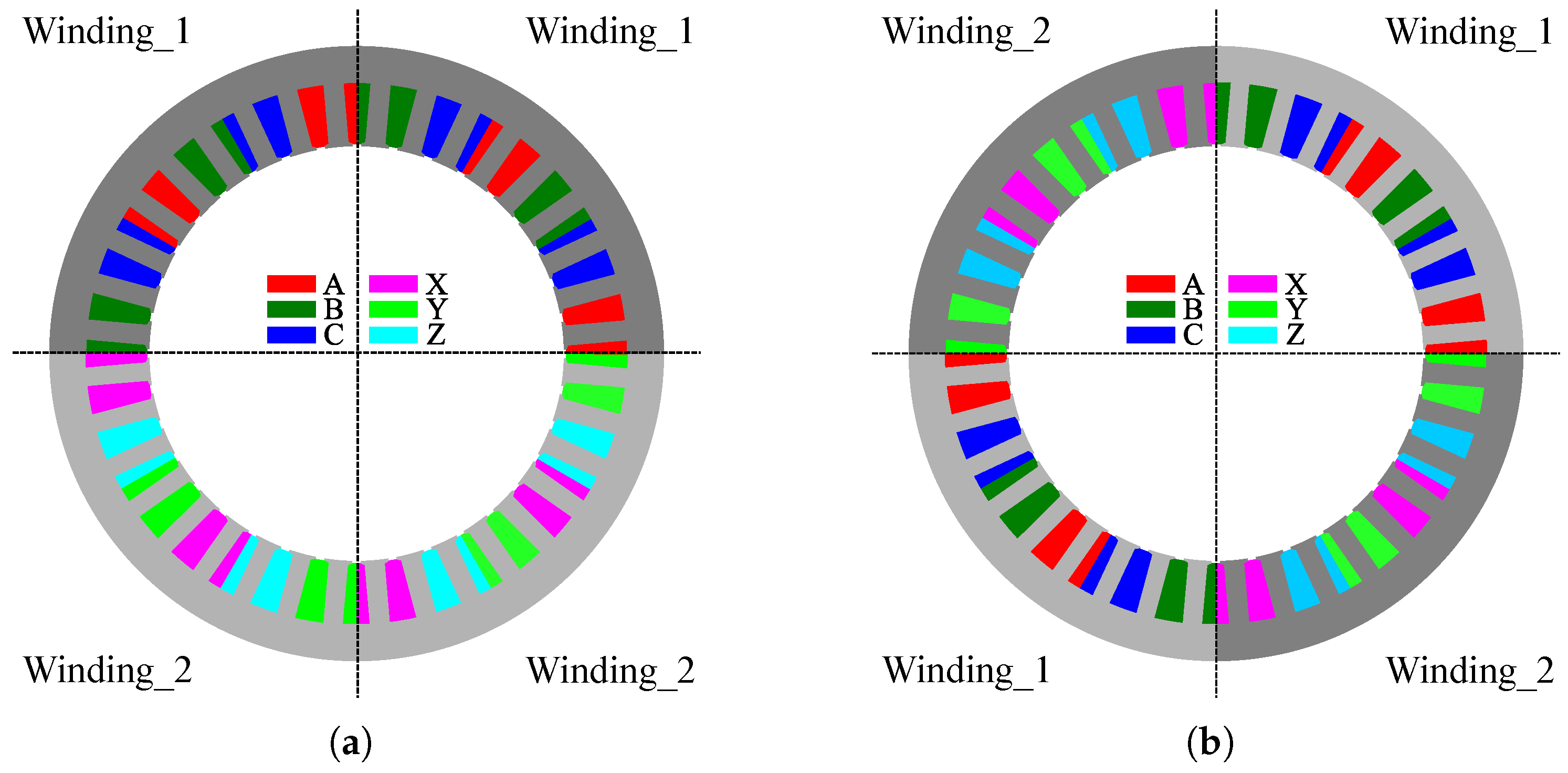
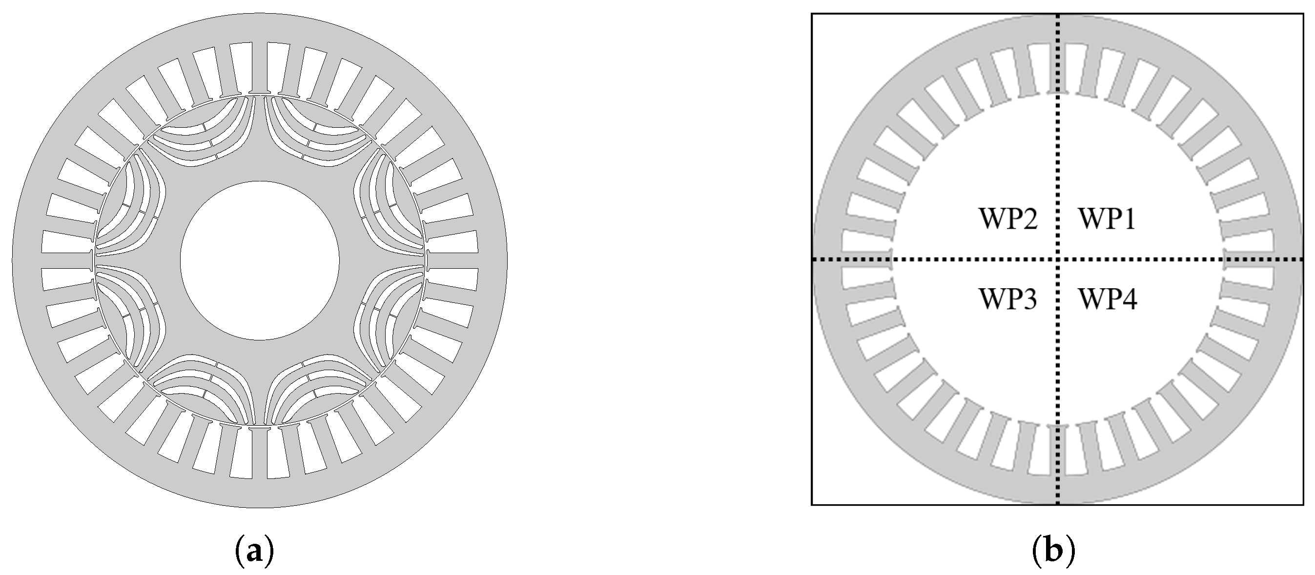
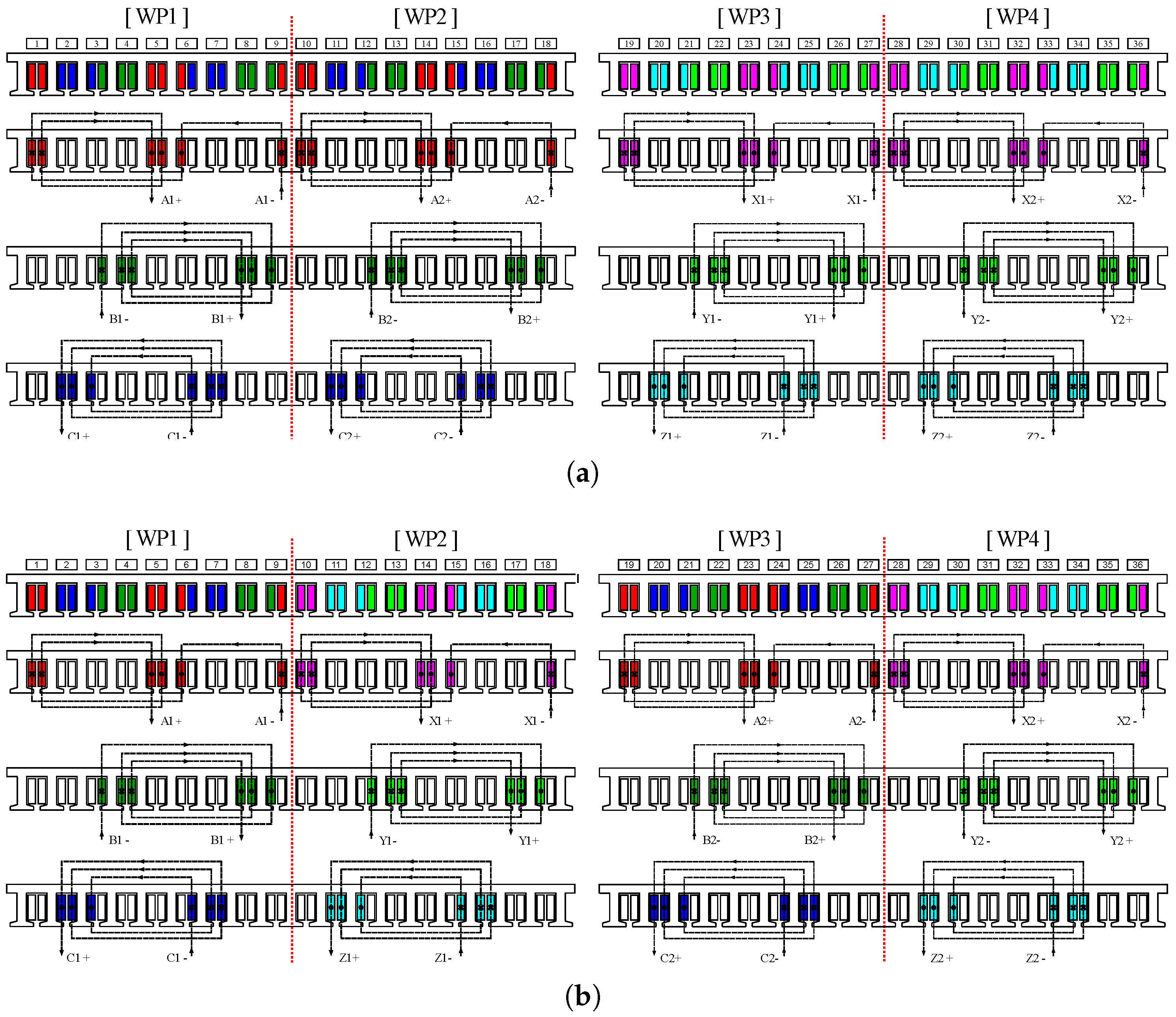
2. DT-SynRM
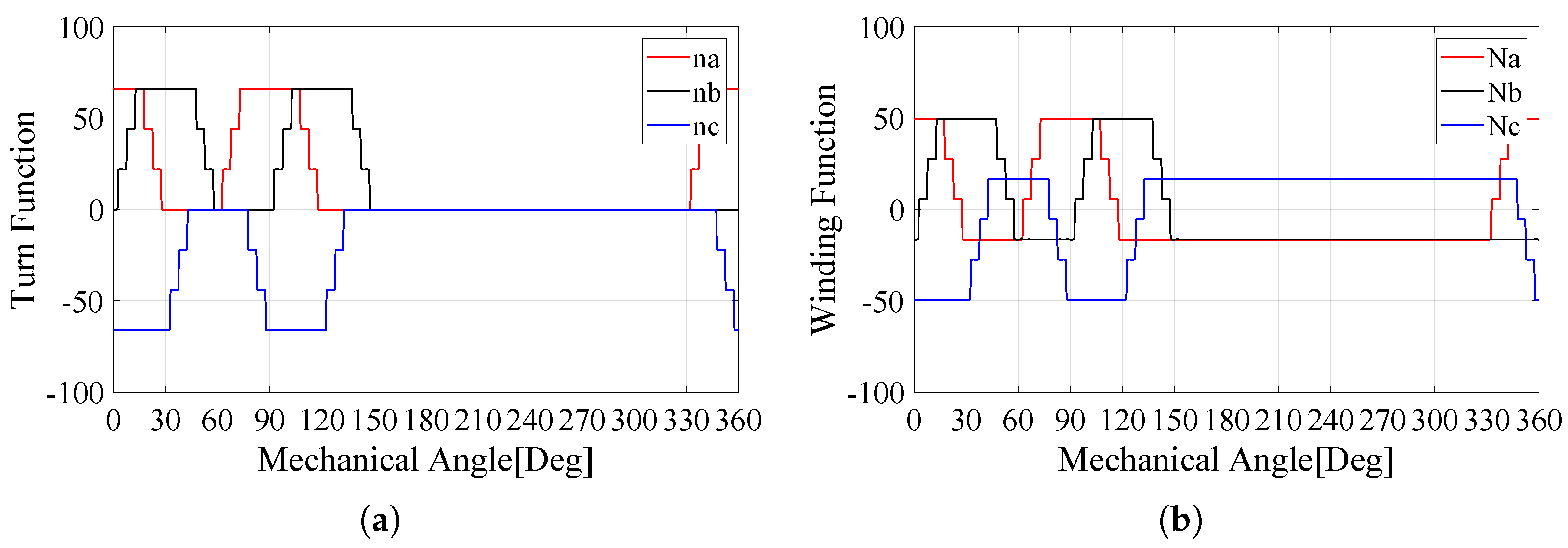
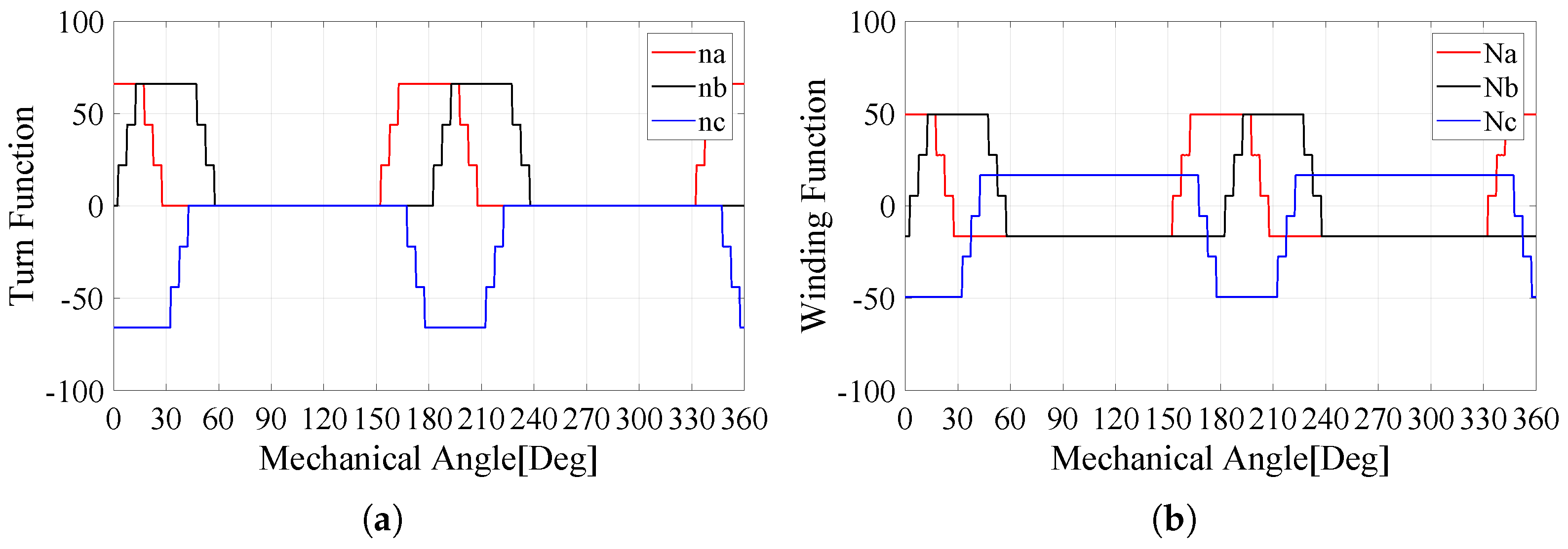
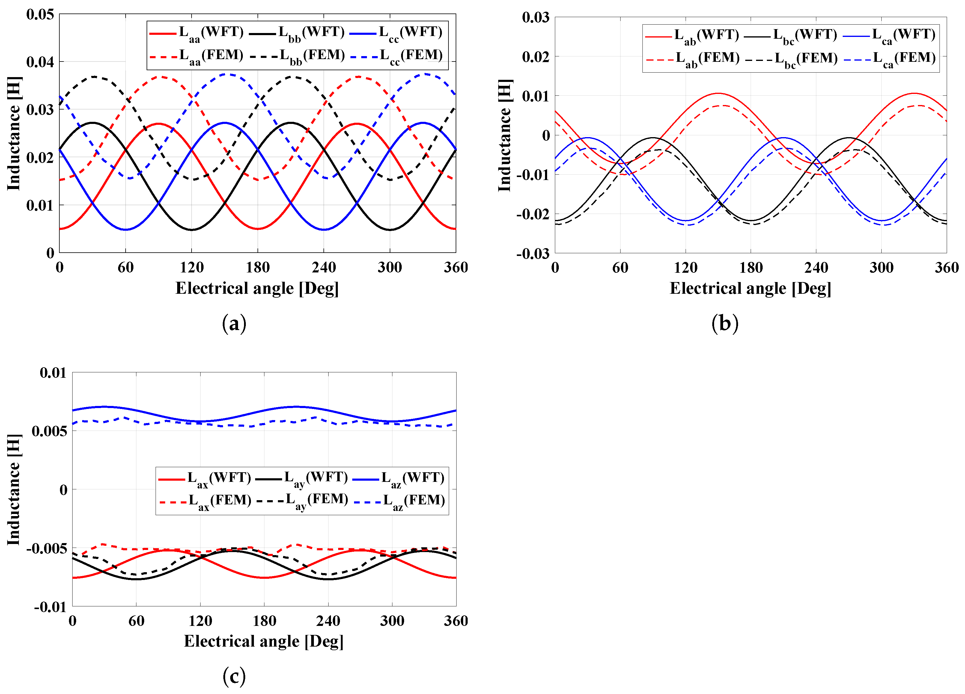
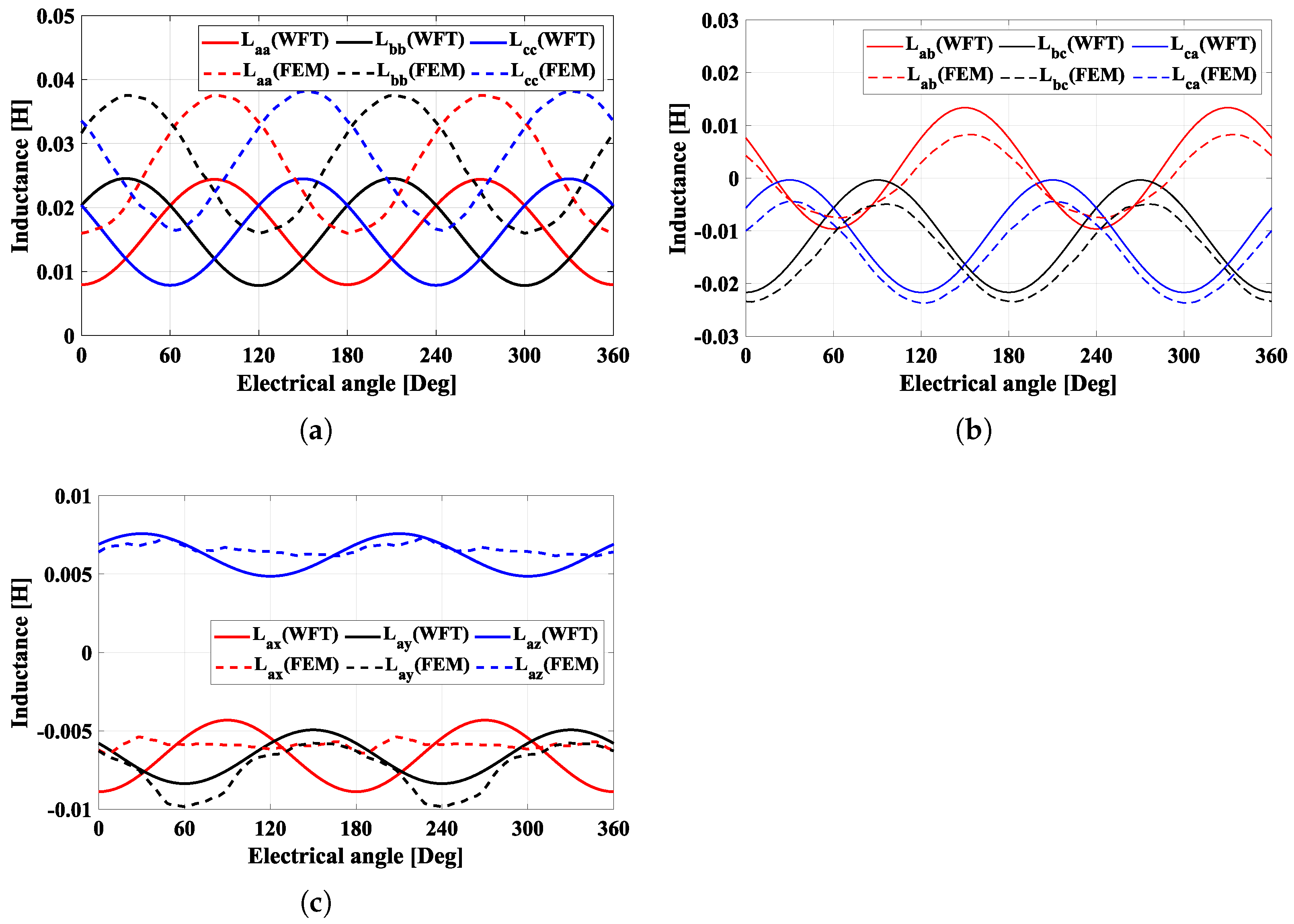
3. Inductance Behaviors
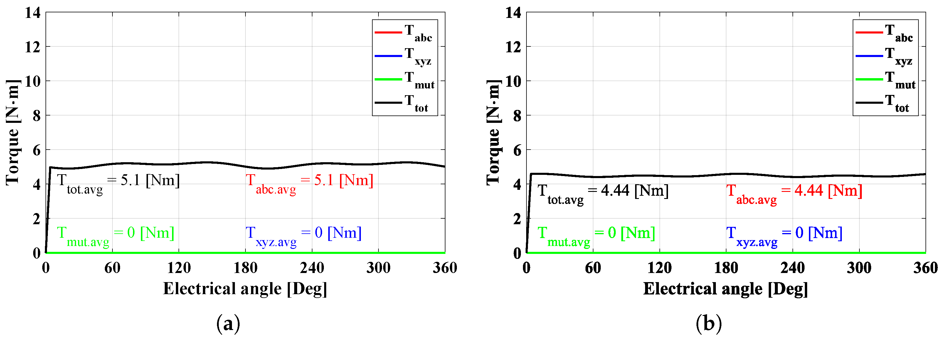
- is the torque component generated by only the ABC-system, which can be calculated as the product of the current and inductance in the ABC-system as follows:
- is the torque component generated by only the XYZ-system, which can be calculated as the product of the current and inductance of the XYZ-system as follows:
- is the torque component generated by only the mutual components between the ABC- and XYZ-systems, which can be calculated as
- is the total torque, which can be calculated as
4. Performance Comparison According to Barrier Design
5. Experimental Results
6. Conclusions
Funding
Data Availability Statement
Conflicts of Interest
References
- Yan, H.; Zhao, W.; Buticchi, G.; Gerada, C. Active thermal control for modular power converters in multi-phase permanent magnet synchronous motor drive system. IEEE Access 2021, 9, 7054–7063. [Google Scholar] [CrossRef]
- Xu, P.; Feng, J.; Guo, S.; Feng, S.; Chu, W.; Ren, Y.; Zhu, Z.Q. Analysis of dual three-phase permanent-magnet synchronous machines with different angle displacements. IEEE Trans. Ind. Electron. 2018, 65, 1941–1954. [Google Scholar] [CrossRef]
- Shah, S.H.; Wang, X.; Azeem, M.; Abubakar, U. Evaluation of magnetomotive force and torque ripples in modular type ipmsm with multi three-phase winding configurations. IEEE Access 2022, 10, 1577–1590. [Google Scholar] [CrossRef]
- Wei, Y.; Qiao, M.; Zhu, P. Fault-tolerant operation of five-phase permanent magnet synchronous motor with independent phase driving control. CES Trans. Electr. Mach. Syst. 2022, 6, 105–110. [Google Scholar] [CrossRef]
- Demir, Y.; Aydin, M. A novel dual three-phase permanent magnet synchronous motor with asymmetric stator winding. IEEE Trans. Magn. 2016, 52, 8105005. [Google Scholar] [CrossRef]
- Ding, W.; Hu, Y.; Wu, L. Investigation and experimental test of fault-tolerant operation of a mutually coupled dual three-phase SRM drive under faulty conditions. IEEE Trans. Power Electron. 2015, 30, 6857–6872. [Google Scholar] [CrossRef]
- Daniels, B.; Gurung, J.; Huisman, H.; Lomonova, E.A. Feasibility study of multi-phase machine winding reconfiguration for fully electric vehicles. In Proceedings of the IEEE Fourteenth International Conference on Ecologicall Vehicles and Renewable Energies, Monte-Carlo, Monaco, 8–10 May 2019. [Google Scholar]
- Pescetto, P.; Cruz, M.F.T.; Stella, F.; Pellegrino, G. Galvanically isolated on-board charger fully integrated with 6-phase traction motor drives. IEEE Access 2023, 11, 26059–26069. [Google Scholar] [CrossRef]
- Chen, W.; Zhu, L.; Li, X.; Shi, T.; Xia, C. Comparing the performance of parallel multi-phase brushless dc motors: A comprehensive analysis. IEEE Trans. Power Electron. 2023, 38, 11290–11303. [Google Scholar] [CrossRef]
- Boglietti, A.; Bojoi, R.; Cavagnino, A.; Tenconi, A. Efficiency analysis of pwm inverter fed three-phase and dual three-phase high frequency induction machines for low/medium power applications. IEEE Trans. Ind. Electron. 2018, 55, 2015–2023. [Google Scholar] [CrossRef]
- Hu, Y.; Zhu, Z.Q.; Liu, K. Current control for dual three-phase permanent magnet synchronous motors according for current unbalance and harmonics. IEEE J. Emerg. Sel. Top. Power Electon. 2014, 2, 272–284. [Google Scholar]
- Yolacan, E.; Guven, M.K.; Aydin, M.; El-refale, A.M. Modeling and experimental verification of an unconventional 9-phase asymmetric winding pm motor dedicated to electric traction applications. IEEE Access 2020, 8, 70182–70192. [Google Scholar] [CrossRef]
- Liang, Z.; Liang, D.; Kou, P.; Jia, S. Postfault control and harmonic current suppression for a symmetrical dual three-phase SPMSM drive under single-phase open-circuit fault. IEEE Access 2020, 8, 67674–67686. [Google Scholar] [CrossRef]
- Onsal, M.; Demir, Y.; Aydin, M. A New nine-phase permanent magnet synchronous motor with consequent pole rotor for high-power traction applications. IEEE Trans. Magn. 2017, 53, 8700606. [Google Scholar] [CrossRef]
- Sun, X.; Xu, N.; Yao, M. Sequential subspace optimization design of a dual three-phase permanent magnet synchronous hub motor based on nsga iii. IEEE Trans. Transp. Electrif. 2023, 9, 622–630. [Google Scholar] [CrossRef]
- Wang, W.; Zhang, J.; Cheng, M.; Li, S. Fault-tolerant control of dual three-phase permanent-magnet synchronous machine drives under open-phase faults. IEEE Trans. Power Electron. 2017, 32, 2052–2063. [Google Scholar] [CrossRef]
- Tessarolo, A. Accurate computation of multiphase synchronous machine inductances based on winding function theory. IEEE Trans. Energy Convers. 2012, 27, 895–904. [Google Scholar] [CrossRef]
- Kim, K.; Park, J.; Hur, J.; Kim, B. Comparison of the fault characteristics of IPM-type and SPM-type BLDC motors under inter-turn fault conditions using winding function theory. IEEE Trans. Ind. Appl. 2014, 50, 986–994. [Google Scholar] [CrossRef]
- Rezaeealam, F.; Rezaeealam, B.; Naeini, V. An improved winding function theory for accurate modeling of small and large air-gap electric machines. IEEE Trans. Mag. 2021, 57, 8104513. [Google Scholar]
- Li, Q.; Fan, T.; Wen, X. Armature-reaction magnetic field analysis for interior permanent magnet motor based on winding function theory. IEEE Trans. Mag. 2013, 49, 1193–1201. [Google Scholar] [CrossRef]
- Ge, B.; Liu, W.; Dong, J.; Liu, M. Extending winding function theory to incorporate secondary effects in the design of induction machines and drives. IEEE J. Emerg. Sel. Top. Power Electron. 2022, 10, 1915–1924. [Google Scholar] [CrossRef]
- Gao, Y.; Qu, R.; Li, D. Improved hybrid method to calculate inductances of permanent magnet synchronous machines with skewed stators based on winding function theory. Chin. J. Electr. Eng. 2016, 2, 52–61. [Google Scholar]
- Jeong, C.; Park, J.; Bianchi, N. Analysis of dual three-phase synchronous reluctance motor by winding function theory. In Proceedings of the 2020 International Conference on Electrical Machines, Gothenburg, Sweden, 23–26 August 2020. [Google Scholar]
- Park, J.; Babetto, C.; Berardi, G.; Hur, J.; Bianchi, N. Comparison of fault characteristics according to winding configurations for dual three-phase synchronous reluctance motor. IEEE Trans. Ind. Appl. 2021, 57, 2398–2406. [Google Scholar] [CrossRef]
- Moghaddam, R.; Gyllensten, F. Novel high-performance synrm design method: An easy approach for a complicated rotor topology. IEEE Trans. Ind. Electron. 2013, 61, 5058–5065. [Google Scholar] [CrossRef]
- Chowdhury, M.; Tesfamicael, A.; Islam, M.; Husain, I. Design optimization of a synchronous reluctance machine for high-performance applications. IEEE Trans. Ind. Appl. 2021, 57, 4720–4732. [Google Scholar] [CrossRef]
- Credo, A.; Fabri, G.; Villani, M.; Popescu, M. A robust design methodology for synchronous reluctance motors. IEEE Trans. Energy Convers. 2020, 35, 2095–2105. [Google Scholar] [CrossRef]


| Item | Unit | Value |
|---|---|---|
| Rated Power | kW | 1.6 |
| Rated Voltage | V | 400 |
| Rated Current | Arms | 8 |
| Rated Speed | RPM | 1000 |
| Rated Torque | Nm | 11 |
| Item | Unit | Value | |
|---|---|---|---|
| Stator | Number of Slots | - | 36 |
| Stator Outer Diameter | mm | 170 | |
| Stator Inner Diameter | mm | 115 | |
| Stack Length | mm | 85 | |
| Air-Gap Length | mm | 0.4 | |
| Rotor | Rotor Outer Diameter | mm | 114.2 |
| Number of Poles | - | 8 | |
| Winding | Number of Turns per Tooth | turns | 22 |
| Parallel Path | - | 1 | |
| Fill Factor | % | 40 | |
| Phase Resistance | 2.5 | ||
Disclaimer/Publisher’s Note: The statements, opinions and data contained in all publications are solely those of the individual author(s) and contributor(s) and not of MDPI and/or the editor(s). MDPI and/or the editor(s) disclaim responsibility for any injury to people or property resulting from any ideas, methods, instructions or products referred to in the content. |
© 2024 by the author. Licensee MDPI, Basel, Switzerland. This article is an open access article distributed under the terms and conditions of the Creative Commons Attribution (CC BY) license (https://creativecommons.org/licenses/by/4.0/).
Share and Cite
Jeong, C. Performance Analysis of Dual Three-Phase Synchronous Reluctance Motor According to Winding Configuration. Electronics 2024, 13, 2821. https://doi.org/10.3390/electronics13142821
Jeong C. Performance Analysis of Dual Three-Phase Synchronous Reluctance Motor According to Winding Configuration. Electronics. 2024; 13(14):2821. https://doi.org/10.3390/electronics13142821
Chicago/Turabian StyleJeong, Chaelim. 2024. "Performance Analysis of Dual Three-Phase Synchronous Reluctance Motor According to Winding Configuration" Electronics 13, no. 14: 2821. https://doi.org/10.3390/electronics13142821