Article

Design and Analysis of a Superconducting Homopolar Inductor Machine for Aerospace Application

1
College of Electrical and Information Engineering, Hunan Institute of Engineering, Xiangtan 411104, China
2
College of Electrical Engineering, Hunan Mechanical Electrical Polytechnic, Changsha 410151, China
*
Author to whom correspondence should be addressed.
Electronics 2024, 13(14), 2830; https://doi.org/10.3390/electronics13142830
Submission received: 26 May 2024 / Revised: 18 June 2024 / Accepted: 24 June 2024 / Published: 18 July 2024

Abstract

:
The electrically excited homopolar inductor machine has a static excitation coil as well as a robust rotor, which makes it attractive in the field of high-speed superconducting machines. This paper designed and analyzed a megawatt class superconducting homopolar inductor machine for aerospace application. To improve the power density, a mass-reduced rotor structure is proposed. Firstly, the main structure parameters of the superconducting homopolar inductor machine are derived based on the required power and speed. Secondly, the electromagnetic performance of the superconducting homopolar inductor machine is analyzed based on the finite element method. Thirdly, a mass-reduced rotor is proposed to improve its power density. The structural performance of the rotor and the electromagnetic performance of the superconducting homopolar inductor machine before and after rotor-mass reduction are evaluated. Compared with the initial rotor, the mass of the mass-reduced rotor is reduced from 66.56 kg to 50.02 kg, which increases the power density by 14.3%. The result shows that a superconducting homopolar inductor machine with a mass-reduced rotor can effectively improve its power density without affecting its output power.

1. Introduction

In recent years, zero-emission all-electric aircraft have attracted a lot of attention [1]. Electric motors play a key role in airborne power systems as energy conversion equipment. The output power of a motor is proportional to its electromagnetic load and rotation speed. Thus, to achieve high power density, the design of motor pursues higher electromagnetic load and higher rotational speed at present. The commonly used permanent magnet motor has a high power density, but the reliability of its permanent magnet would be greatly threatened under the extreme working conditions of aviation electromechanical systems [2].
With the development of superconducting technology, the miniaturized, lightweight and high-power-density superconducting motor has become a research hotspot. Due to its higher reliability, the partially superconducting motor with a superconducting excitation coil has a wider range of application compared to the fully superconducting motor [3]. The superconducting excitation coil allows a large magnetic load to be applied to the motor, overcoming the disadvantages of conventional electrically excited synchronous motors. However, for rotor superconducting synchronous motors, the design of the cooling device is complicated and its reliability is reduced due to the excitation coil being in a state of high-speed rotation [4,5]. Thus, synchronous motors with superconducting stator static excitation have attracted much attention in the aerospace industry due to their high reliability and the low complexity of their cooling systems [6]. In [7], a new stator high-temperature superconducting field-modulated machine with a simple structure was proposed. A stator flux modulation machine was proposed in [2], which realized the static excitation of the superconducting coil. However, the mismatch between the excitation field and the armature fundamental field leads to serious AC copper losses; as a result, the efficiency of the machine is reduced. A superconducting vernier reluctance motor was proposed in [8], but it is still a challenge to cool the armature and the superconducting coil located on the stator side.
The superconducting homopolar induction machine (SHIM) stands out among many superconducting motors for its advantages of static excitation, simple structure and high-speed operation [9,10]. Several studies have presented the conceptual design of the SHIM [11,12]. In [13], a 10 MW class superconducting homopolar generator was presented for wind turbines. In [14], a 2 MW, 25000 rpm SHIM using ReBCO field coils was proposed for aircraft propulsion to reduce development and construction time and cost. In [15], to ensure the safe operation and improve the performance of SHIM, the superconducting coil in SIM was designed considering the critical current reduction in local turn. However, these studies did not deeply explore how to improve the power density of the SHIM. Other research focused on achieving high rotational speed of SHIM [16,17]. In [18], to suppress the alternating field acting on the superconducting coil in SHIM, a combined method using two sets of U-shaped armature winding and an L-shaped flux diverter was proposed. In addition, the loss of the superconducting magnet in SHIM is analyzed and calculated in [19]. However, these studies lack analysis into the reliability of SHIM in high-speed operations, especially the rotor.
To better meet the needs of future aerospace motors, SHIM is taken as a research object, and a 1 MW, 21,000 rpm SHIM is designed in this paper. The electromagnetic and structural properties of SHIM are analyzed through the finite element method (FEM). To reduce the weight of the SHIM, a rotor weight reduction structure is proposed. The rest of this paper is arranged as follows: In Section 2, the topology of the SHIM and its operating principle are introduced. In Section 3, the main dimensions of the SHIM and the mathematical model of its basic electromagnetic parameters are modeled. Then, the electromagnetic performance of SHIM is evaluated using the FEM. In Section 4, a mass-reduced rotor is proposed to improve the power density of SHIM, and the electromagnetic performance of the SHIM before and after mass reduction is compared. The conclusions of this paper are drawn in Section 5.

2. Topology and Operation Principle

The structure of the SHIM is shown in Figure 1. The shell is made of material with good magnetic permeability and is located on the outermost side. Silicon steel sheets are laminated along the axial direction to form the slotless stator cores. The core mass is reduced through drilling the stator cores [20]. A set of armature winding is placed on the inner wall of the stator. The rotor of the SHIM is forged from a single piece of high-strength alloy steel, which allows it to operate at extremely high rotational speeds. The rotor teeth are evenly distributed on the left and right sides of the rotor, and the rotor tooth axes on both sides differ in space by π electrical degree.
To pursue a higher magnetic load and reduce excitation loss, the conventional copper excitation winding is replaced by the superconducting coil that is stationarily installed between the left and right stator cores. Figure 2 shows the two-dimensional cross-section view of the cryostat. The static excitation of the superconducting coil avoids the introduction of rotary sealing and cooling, which improves the reliability of the system.
The flux generated by the superconducting excitation winding is shown by the red dotted line in Figure 1. The air-gap flux density has AC components due to the cogging effect of the rotor. As the rotor rotates, a back electromotive force (EMF) is generated on the armature winding.

3. Electromagnetic Performance Design

3.1. Calculation of Main Structure Parameters

The rated power P of SHIM can be expressed as follows:
P = m 1 E I
The back EMF E of SHIM can be expressed as follows:
E = 4 k N m f N k d p Φ
The flux per pole is expressed as follows:
Φ = B max α δ τ l e f
Combining (1) to (3), the relationship between the main dimensions of SHIM can be expressed as follows [21]:
D 2 l e f n P = 6.1 α δ k N m k d p B max A
Under the premise of ignoring the saturation, the amplitude of the air-gap flux density can be expressed as follows:
B max = F g a p Λ max = N f i f μ 0 / ( 2 g min )
It can be seen from (4) and (5) that when the rated power of the SHIM is constant, the effective length and diameter of the armature winding are directly related to the line load A and magnetic load Bmax. The larger the product of A and Bmax, the smaller the volume of the SHIM. In addition, the ampere-turns of the excitation winding can be determined according to the given magnetic load and the minimum length of the physical air gap.

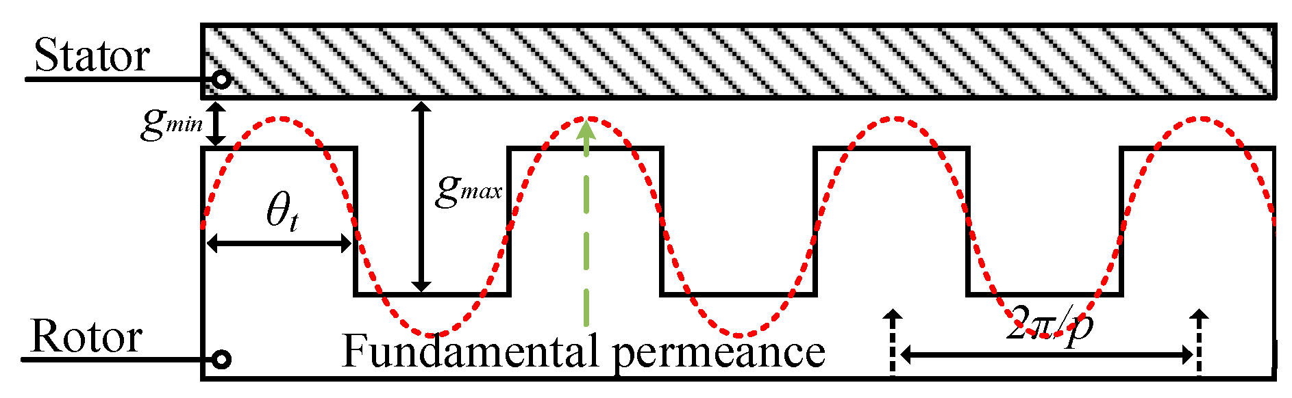
3.2. Calculation of Electromagnetic Parameters

The calculation of electromagnetic parameters needs to first obtain the mathematical model of the no-load air-gap flux density. The two-dimensional expanded view of the rotor along the circumference is given in Figure 3. Since the toothless stator is adopted in SHIM, only the specific permeability function on the rotor side needs to be considered.
The specific permeability functions of the air gaps on the left and right sides can be, respectively, expressed as follows [22]:
{ Λ L ( θ θ r ) = 0 Λ m cos m p ( θ θ r ) Λ R ( θ θ r ) = 0 Λ m cos m p ( θ θ r π p )
Then, the open-circuit air-gap flux density on the left and right sides can be expressed as follows:
{ B L ( θ θ r ) = F g a p 0 Λ m cos m p ( θ θ r ) B R ( θ θ r ) = F g a p 0 Λ m cos m p ( θ θ r π p )
Based on the idea of space overlay method [23], the composite air-gap flux density (BC) is expressed as
B c ( θ , θ r ) = B L ( θ , θ r ) + B R ( θ , θ r )
The open-circuit flux linkage is represented as follows [24]:
λ i , j , k ( θ r ) = D 2 0 L e f 0 2 π N i , j , k ( θ ) B c ( θ , θ r ) d θ d l
The back EMF of SHIM is expressed as follows [24]:
e i , j , k ( θ r ) = d λ i , j , k ( θ r ) d θ r d θ r d t = ω m e c d λ i , j , k ( θ r ) d θ r
The torque of SHIM can be expressed by the product of back EMF and phase current as shown below [25], and in (11).
T e l e c = P / ω m e c = ( e a i a + e b i b + e c i c ) / ω m e c

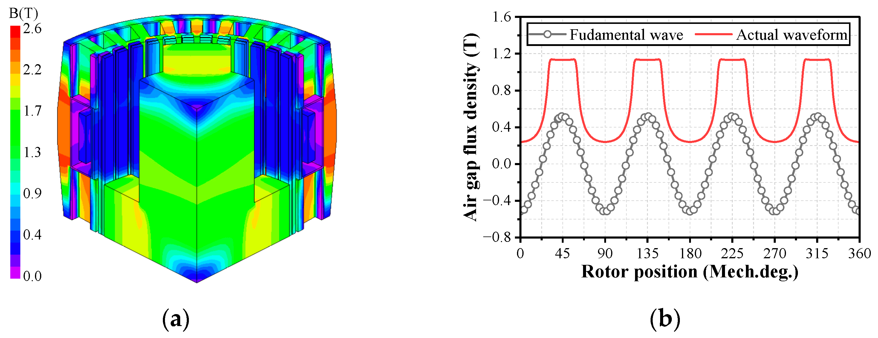
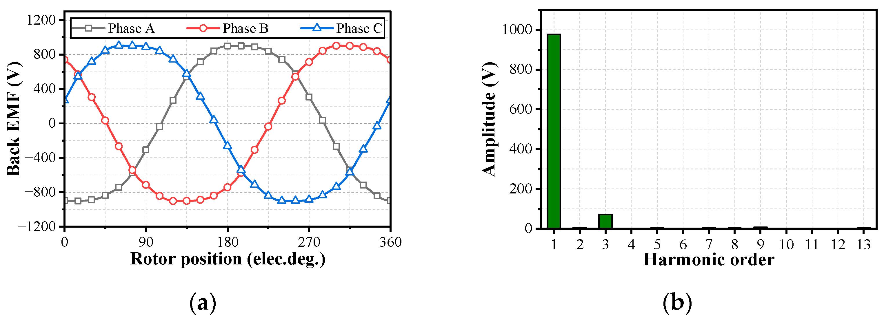
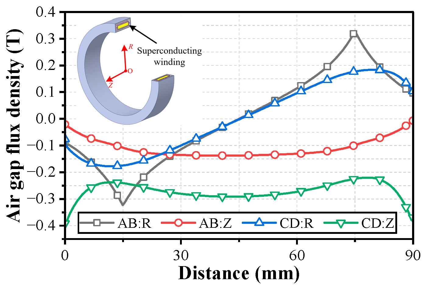
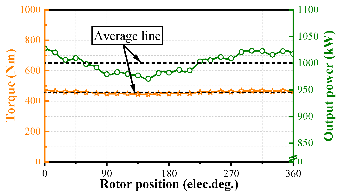
3.3. Numerical Analysis of Electromagnetic

Based on the main dimensional relationship of the SHIM, a SHIM with the power of one megawatt is designed, and its no-load and load performance are evaluated by FEM. The detailed design process for the SHIM is given in [15,26]. The materials of each component and the main parameters of SHIM are shown in Table 1 and Table 2. It is worth noting that the saturation magnetic density of the 1J22 is 2.4 T [27], and higher saturation magnetic density can make the magnetic load of the SHIM designed higher. In addition, combined with the advantages of superconducting field winding, the power density of the machine can be further improved.
The no-load magnetic field distribution and air-gap flux density of SHIM under rated excitation conditions are shown in Figure 4. The maximum magnetic density in the shell is 2.48 T, the amplitude of the air-gap flux density is 1.13 T, and the fundamental waveform amplitude is 0.52 T. The back EMF and its amplitude spectrum of the SHIM in the no-load state are given in Figure 5. The toothless stator and the short-pitch armature winding make the back EMF have good sinusoidal property in one electrical cycle.
The distribution of magnetic field around the superconducting coil is given in Figure 6, where AB is the distance from point A to point B in Figure 2. CD has a similar meaning to AB. Because the excitation flux needs to be closed axially through the rotor, the axial magnetic field at the bottom position of the excitation window (CD) is larger than that at the middle position (AB). Conversely, the radial flux density amplitude at CD is smaller than that at AB.
The output torque and power waveforms of SHIM are shown in Figure 7. In the rated state, the output power is one megawatt, and the torque is about 455 Nm.

4. Mechanical Performance

For a rotor rotating at high speed, its rotational speed is limited by the strength of material. The designed SHIM not only needs to meet the performance requirements of the electromagnetic, but also needs to meet the strength requirements of material for its high-speed rotating condition.

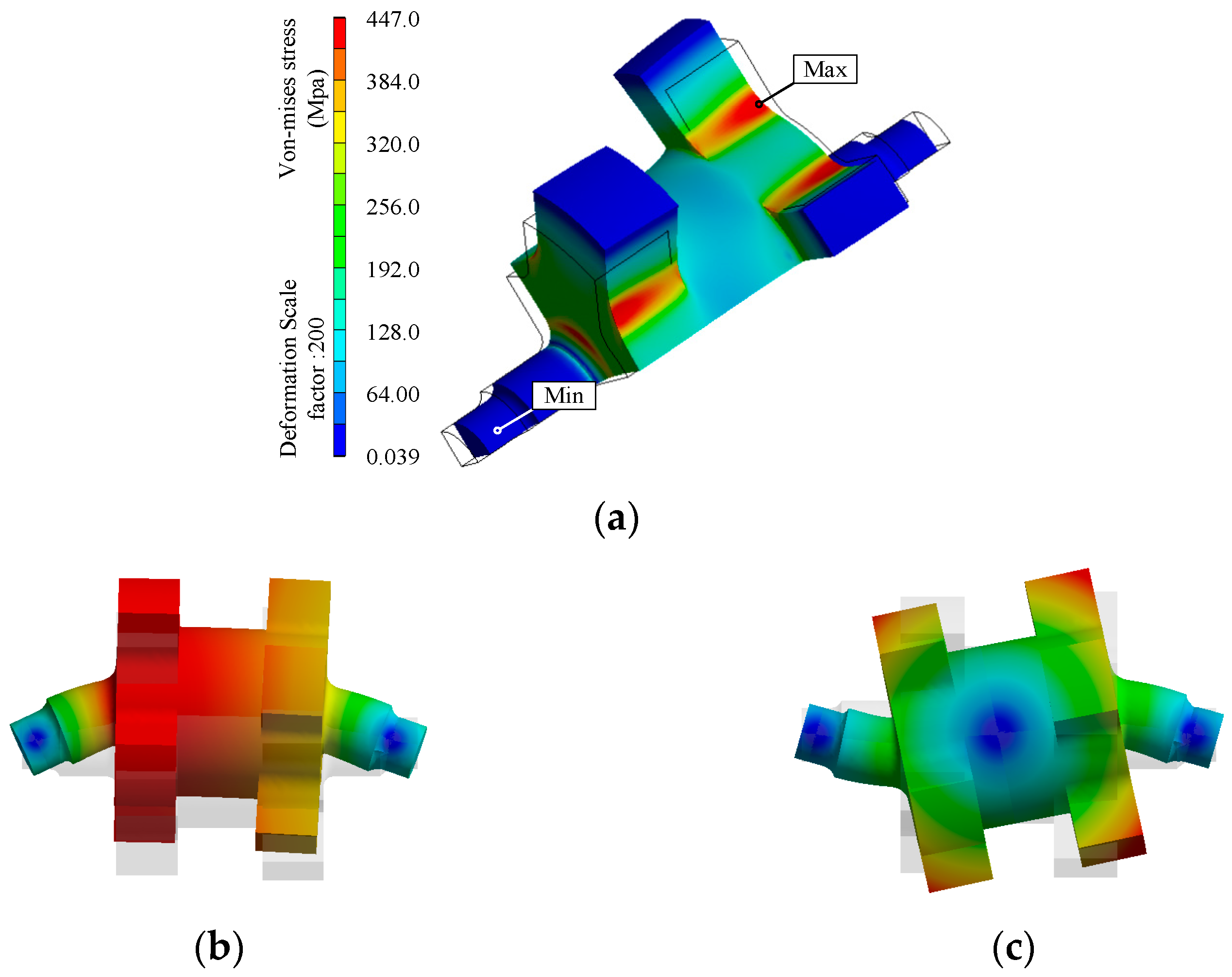
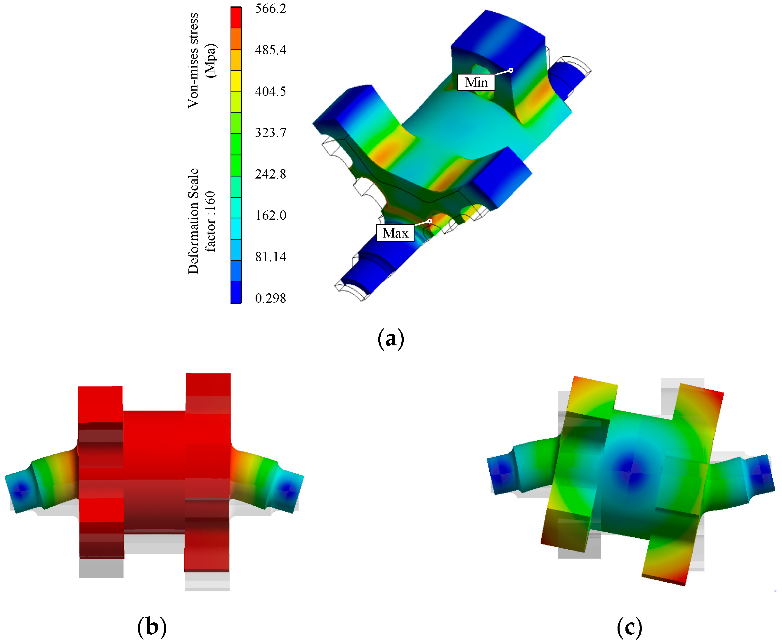
4.1. Structure Analysis of Rotor

Since the rotor is evenly distributed with rotor tooth and rotor slots, it becomes difficult to calculate the rotor stress analytically.
In this paper, the FEM is adopted to analyze and calculate the stress and modal of the rotor. When the rotor speed is 21,000 rpm, its von Mises stress distribution, first-order and second-order bending mode are given in Figure 8. As shown in Figure 8a, the maximum value of von Mises stress occurs at the rounded corner of the connection position between the rotor teeth and the rotor slot, and the value is 447 Mpa. The yield strength of 40 Cr used for the rotor is 800 Mpa, and the safety factor of the rotor strength under rated operation is calculated to be 1.79. For plastic materials, the safety factor range of its strength is 1.2~2.5; thus, the rotor can operate safely under rated working conditions. In addition, the first- and second-order bending modes of the rotor are given in Figure 8b,c. The corresponding natural frequencies are 753.74 Hz and 1740.8 Hz, respectively. The mechanical frequency corresponding to SHIM at rated speed is 350 Hz, which is lower than 70% of the first-order mode, indicating that the rotor would not have any resonance phenomena at rated operation conditions.

4.2. Weight-Saving Design of Rotor

The mass of the SHIM for all-electric aircraft needs to be reduced as much as possible in order to reduce the total mass of the power supply system and to increase the power density of the SHIM. Based on the results of the previous rotor strength analysis, it is clear that this can be achieved by sacrificing the strength performance of the rotor, subject to safe operation. The original and mass-reduced models of the rotor are shown in Figure 9. The von Mises stress distribution, first-order bending mode and second-order bending mode of the mass-reduced rotor at rated speed are shown in Figure 10. The maximum von Mises stress is 566.2 Mpa, and the corresponding frequencies of the first- and second-order bending modes are 680.91 Hz and 1581.9 Hz, respectively. Compared with the original rotor, the von Mises stress increases by 26.7%, and the frequencies corresponding to the first- and second-order bending modes decrease by 9.7% and 9.1%, respectively. Notably, the strength safety factor of the mass-reduced rotor is 1.41, and its mechanical frequency is still lower than 70% of the first-order natural frequency, indicating that the mass-reduced rotor is still in a safe working state.
The mass property comparison between the mass-reduced rotor and the original rotor is shown in Table 3. Compared with the original rotor, the mass of the mass-reduced rotor is reduced by 24.9% and the moment of inertia is reduced by 17.9%. The change in rotor would inevitably lead to the decrease in SHIM output performance at rated state. The no-load flux density distribution of the SHIM with a mass-reduced rotor and the waveform of air-gap flux density are shown in Figure 11. Compared with Figure 4, the flux density of the rotor becomes saturated, and the maximum flux density of the shell is reduced from 2.48 to 2.24 T. In addition, the saturation phenomenon in the mass-reduced rotor leads to the decrease in the amplitude of the air-gap flux density.
To make the output performance of the SHIM after mass reduction be the same as that before mass reduction, it is necessary to increase the magnetic load or electrical load. According to Figure 11, the middle part of the shell is already in a saturated state, and further increasing the ampere-turns of excitation winding has no obvious effect on increasing the output performance of SHIM. Therefore, the method of increasing electrical load is adopted to improve the torque output capacity of SHIM.
The performance of SHIM before and after mass reduction with the same output power is compared in Table 4. To make the SHIM output the same power, the armature current density of the SHIM with the mass-reduced rotor should be increased while keeping the excitation ampere-turns unchanged. After mass reduction, the efficiency of SHIM is reduced by 0.3%, but its power density is increased by 14.3%. If the electromagnetic load is kept constant, the output power and power density of SHIM decrease after weight reduction. From the point of view of power density, the SHIM with the mass-reduced rotor has significantly better electromagnetic properties.

5. Conclusions

In this paper, the design and analysis of a superconducting homopolar inductor machine (SHIM) with a power level of one megawatt are carried out. Firstly, to obtain the initial structure parameters of the SHIM, the main dimensional relationships of the SHIM are established. Secondly, the electromagnetic performance of SHIM is analyzed based on the finite element method. Since the slotless structure is adopted, the harmonic content of air-gap flux density and back-EMF are low. The magnetic field acting on superconducting coil is symmetrically distributed. Then, in order to improve the power density of SHIM, a mass-reduced rotor topology is proposed. The mechanical frequence of mass-reduced rotor is lower than 70% of the first-order natural frequency. After the rotor mass is reduced, the magnetic field acting on the superconducting excitation winding can be weakened. In addition, when the same power is taken as the output target, the power density of the SHIM can be increased by 14.3% after mass reduction.
Although this paper is devoted to the design and analysis of megawatt class SHIM, the method of improving power density in this paper is also applicable to other types of superconducting machines.

Author Contributions

Conceptualization and writing—original draft preparation, J.W.; designing and simulation, C.G.; investigation and validation, W.Z.; Writing—review and editing, Q.W. All authors have read and agreed to the published version of the manuscript.

Funding

This research was funded by the Natural Science Foundation of Hunan Province (2022JJ30195).

Data Availability Statement

Data are contained within the article.

Conflicts of Interest

The authors declare no conflicts of interest.

Nomenclature

m1Phase number of armature
IPhase current
kdpWinding coefficient
ΦMagnetic flux per pole
αδPole arc coefficient
lefEffective length of armature
AArmature winding line-load
FgapMagnetomotive force
gminMinimum the airgap length
ifExcitation current
ΛLPermeability function of left air gap
Ni,j,k(θ)Winding function
EBack EMF
kNmWaveform factor
fElectric frequence
BmaxMaximum value of air-gap flux density
τPole pitch
nSynchronous speed
DArmature diameter
ΛmaxMaximum of permeability
NfNumber of turns of excitation winding
μ0Vacuum permeability
ΛRPermeability function of right air gap
ωmecMechanical angular velocity of rotor

References

  1. Dezhin, D.; Ivanov, N.; Kovalev, K.; Kobzeva, I.; Semenihin, V. System Approach of Usability of HTS Electrical Machines in Future Electric Aircraft. IEEE Trans. Appl. Supercond. 2018, 28, 1–5. [Google Scholar] [CrossRef]
  2. Zhang, Y.; Cheng, Y.; Qu, R.; Li, D.; Gao, Y.; Wang, Q. AC Loss Analysis and Modular Cryostat Design of a 10-MW High-Temperature Superconducting Double Stator Flux Modulation Machine. IEEE Trans. Ind. Applicat. 2022, 58, 7153–7162. [Google Scholar] [CrossRef]
  3. Liu, Y.; Ou, J.; Cheng, Y.; Schreiner, F.; Zhang, Y.; Vargas-Llanos, C.; Grilli, F.; Qu, R.; Doppelbauer, M.; Noe, M. Investigation of AC Loss of Superconducting Field Coils in a Double-Stator Superconducting Flux Modulation Generator by Using T-A Formulation Based Finite Element Method. Supercond. Sci. Technol. 2021, 34, 055009. [Google Scholar] [CrossRef]
  4. Qu, R.; Liu, Y.; Wang, J. Review of Superconducting Generator Topologies for Direct-Drive Wind Turbines. IEEE Trans. Appl. Supercond. 2013, 23, 5201108. [Google Scholar] [CrossRef]
  5. Chow, C.C.T.; Ainslie, M.D.; Chau, K.T. High Temperature Superconducting Rotating Electrical Machines: An Overview. Energy Rep. 2023, 9, 1124–1156. [Google Scholar] [CrossRef]
  6. Cheng, M.; Zhu, X.; Wang, Y.; Wang, R.; Wang, W. Effect and Inhibition Method of Armature-Reaction Field on Superconducting Coil in Field-Modulation Superconducting Electrical Machine. IEEE Trans. Energy Convers. 2020, 35, 279–291. [Google Scholar] [CrossRef]
  7. Li, X.; Liu, S.; Wang, Y. Design and Analysis of a Stator HTS Field-Modulated Machine for Direct-Drive Applications. IEEE Trans. Appl. Supercond. 2017, 27, 1–5. [Google Scholar] [CrossRef]
  8. Jia, S.; Qu, R.; Li, J.; Fang, H.; Li, D. A Novel Vernier Reluctance Fully Superconducting Direct Drive Synchronous Generator With Concentrated Windings for Wind Power Application. IEEE Trans. Appl. Supercond. 2016, 26, 1–5. [Google Scholar] [CrossRef]
  9. Sivasubramaniam, K.; Zhang, T.; Lokhandwalla, M.; Laskaris, E.T.; Bray, J.W.; Gerstler, B.; Shah, M.R.; Alexander, J.P. Development of a High Speed HTS Generator for Airborne Applications. IEEE Trans. Appl. Supercond. 2009, 19, 1656–1661. [Google Scholar] [CrossRef]
  10. Berg, F.; Palmer, J.; Miller, P.; Dodds, G. HTS System and Component Targets for a Distributed Aircraft Propulsion System. IEEE Trans. Appl. Supercond. 2017, 27, 1–7. [Google Scholar] [CrossRef]
  11. Sivasubramaniam, K.; Laskaris, E.T.; Shah, M.R.; Bray, J.W.; Garrigan, N.R. High-Temperature Superconducting Homopolar Inductor Alternator for Marine Applications. IEEE Trans. Appl. Supercond. 2008, 18, 1–6. [Google Scholar] [CrossRef]
  12. Lokhandwalla, M.; Haran, K.S.; Alexander, J.P. Scaling Studies of High Speed High Temperature Superconducting Generator. In Proceedings of the 2012 XXth International Conference on Electrical Machines, Marseille, France, 2–5 September 2012; IEEE: Piscataway, NJ, USA, 2012; pp. 751–756. [Google Scholar]
  13. Jeong, J.-S.; An, D.; Hong, J.-P.; Kim, H.-J.; Jo, Y.-S. Design of a 10-MW-Class HTS Homopolar Generator for Wind Turbines. IEEE Trans. Appl. Supercond. 2017, 27, 1–4. [Google Scholar] [CrossRef]
  14. Kalsi, S.; Hamilton, K.; Buckley, R.; Badcock, R. Superconducting AC Homopolar Machines for High-Speed Applications. Energies 2018, 12, 86. [Google Scholar] [CrossRef]
  15. Pan, Y.; Yang, J.; Li, Q.; Luo, X.; Huang, S.; Gao, C.; Ma, J. Design of HTS Excitation Coil for Homopolar Inductor Machine Considering Critical Current Reduction of Local Turn. IEEE Trans. Ind. Appl. 2024, 1–9. [Google Scholar] [CrossRef]
  16. Sivasubramaniam, K.; Laskaris, E.T.; Lokhandwalla, M.; Zhang, T.; Bray, J.W.; Gerstler, B.; Shah, M.R.; Alexander, J.P. Development of a High Speed Multi-Megawatt HTS Generator for Airborne Applications. In Proceedings of the 2008 IEEE Power and Energy Society General Meeting—Conversion and Delivery of Electrical Energy in the 21st Century, Pittsburgh, PA, USA, 20–24 July 2008; IEEE: Piscataway, NJ, USA, 2008; pp. 1–4. [Google Scholar]
  17. Li, W.; Chau, K.T.; Ching, T.W.; Wang, Y.; Chen, M. Design of a High-Speed Superconducting Bearingless Machine for Flywheel Energy Storage Systems. IEEE Trans. Appl. Supercond. 2015, 25, 1–4. [Google Scholar] [CrossRef]
  18. Pan, Y.; Yang, J.; Li, Q.; Huang, S.; Gao, C.; Ma, J. Investigation and Suppression of External Alternating Field of HTS Excitation Coil in Homopolar Inductor Machine. IEEE Trans. Magn. 2024, 1. [Google Scholar] [CrossRef]
  19. Ma, J.; Pan, Y.; Luo, X.; Xiao, H.; Yang, J.; Simpson, N.; Mellor, P. Design of a 10 kW Superconducting Homopolar Inductor Machine Based on HTS REBCO Magnet. IEEE Trans. Appl. Supercond. 2024, 34, 1–7. [Google Scholar] [CrossRef]
  20. Pan, Y.; Yang, J.; Li, Q.; Luo, X.; Huang, S.; Ma, J. Optimal Design of a High Temperature Superconducting Homopolar Inductor Machine. In Proceedings of the 2023 26th International Conference on Electrical Machines and Systems (ICEMS), Zhuhai, China, 5–8 November 2023; pp. 3920–3925. [Google Scholar]
  21. Dai, S.; Yang, J.; Liu, H.; Feng, Y.; Huang, S. Comparative Study on the Performance of High-Speed IPM Motor with Single-Layer PM for Electric Spindle. In Proceedings of the 2022 IEEE 5th International Electrical and Energy Conference (CIEEC), Nangjing, China, 27–29 May 2022; pp. 963–968. [Google Scholar]
  22. Ye, C.; Yang, J.; Xiong, F.; Zhu, Z.Q. Relationship Between Homopolar Inductor Machine and Wound-Field Synchronous Machine. IEEE Trans. Ind. Electron. 2020, 67, 919–930. [Google Scholar] [CrossRef]
  23. Lou, Z.; Yu, K.; Wang, L.; Ren, Z.; Ye, C. Two-Reaction Theory of Homopolar Inductor Alternator. IEEE Trans. Energy Convers. 2010, 25, 677–679. [Google Scholar] [CrossRef]
  24. Li, Q.; Yang, J.; Huang, S.; Liu, P.; Feng, Y.; Wang, L. No-Load Electromagnetic Performance Analysis of a Mechanically Modulated Permanent Magnet Homopolar Inductor Machine. IEEE Trans. Transp. Electrif. 2022, 8, 1168–1181. [Google Scholar] [CrossRef]
  25. Yang, J.; Ye, C.; Huang, S.; Li, Y.; Xiong, F.; Zhou, Y.; Xu, W. Analysis of the Electromagnetic Performance of Homopolar Inductor Machine Through Nonlinear Magnetic Equivalent Circuit and Air-Gap Permeance Function. IEEE Trans. Ind. Appl. 2020, 56, 267–276. [Google Scholar] [CrossRef]
  26. Yang, J.; Liu, P.; Ye, C.; Wang, L.; Zhang, X.; Huang, S. Multidisciplinary Design of High-Speed Solid Rotor Homopolar Inductor Machine for Flywheel Energy Storage System. IEEE Trans. Transp. Electrific. 2021, 7, 485–496. [Google Scholar] [CrossRef]
  27. Krings, A.; Cossale, M.; Tenconi, A.; Soulard, J.; Cavagnino, A.; Boglietti, A. Magnetic Materials Used in Electrical Machines: A Comparison and Selection Guide for Early Machine Design. IEEE Ind. Appl. Mag. 2017, 23, 21–28. [Google Scholar] [CrossRef]
Figure 1. Topology of superconducting homopolar inductor machine.
Electronics 13 02830 g001
Figure 2. Two-dimensional cross-section of the super-conducting winding.
Electronics 13 02830 g002
Figure 3. Two-dimensional expanded view of the rotor along the circumference.
Electronics 13 02830 g003
Figure 4. The static magnetic field flux density cloud diagram of SHIM and the air-gap flux density on one side of the air gap. (a) Magnetic field flux density cloud diagram. (b) Air-gap flux density.
Electronics 13 02830 g004
Figure 5. Phase back EMF and its amplitude spectrum. (a) Waveform of back EMF. (b) Amplitude spectrum.
Electronics 13 02830 g005
Figure 6. Magnetic field distribution around the superconducting coil.
Electronics 13 02830 g006
Figure 7. Output torque and power waveforms.
Electronics 13 02830 g007
Figure 8. Structure analysis and modal analysis of rotor. (a) Von mises stress distribution. (b) First-order mode (Frequency = 753.74 Hz). (c) Second-order mode (Frequency = 1740.8 Hz).
Electronics 13 02830 g008
Figure 9. Three-dimensional models of the original rotor and the mass-reduced rotor. (a) Original rotor. (b) Mass-reduced rotor. (c) Sectional view of the weight-reduction rotor.
Electronics 13 02830 g009
Figure 10. Von Mises stress distribution, first-order bending mode and second-order bending mode of the reduced rotor at rated speed. (a) Von mises stress distribution. (b) First-order bending mode. (c) Second-order bending mode.
Electronics 13 02830 g010
Figure 11. The static field magnetic density distribution of the SHIM with mass-reduced rotor and the waveform of air-gap flux density. (a) Static field magnetic density distribution. (b) Air-gap flux density.
Electronics 13 02830 g011
Table 1. Material and mass of each component.
ComponentsMaterialsMass (kg)
Stator1J2227.32
Rotor40Cr66.56
Shell1J2235.36
Armature windingLitz wire12.32
Table 2. Main parameters of SHIM.
Parameters (Unit)Value
Inner diameter of stator yoke (mm)316
Outer radius of rotor (mm)145
Effective length of the rotor (mm)130
Pole-pairs (-)4
Coil pitch (-)5
Synchronous speed (rpm)21,000
Thickness of stator yoke (mm)40
Rotor slot depth (mm)55
Physical air-gap length (mm)13
Virtual slots of the stator (-)48
Ampere-turns of exciting winding (AT)30,000
Rated power (kW)1000
Table 3. Mass property comparison.
Volume (m3)Mass (kg)Moment of Inertia (kg.m2)
Original rotor0.008566.560.4235
Mass-reduced rotor0.006450.020.3476
Table 4. Performance comparison.
Volume (m3)Mass (kg)Moment of Inertia (kg.m2)Kilowatt Per
Kilogram (kW/kg)
SHIM with original rotor13.0100097.4About 7.1
SHIM with mass-reduced rotor13.078898.5About 6.3
SHIM with mass-reduced rotor16.5100097.1About 8.0
Disclaimer/Publisher’s Note: The statements, opinions and data contained in all publications are solely those of the individual author(s) and contributor(s) and not of MDPI and/or the editor(s). MDPI and/or the editor(s) disclaim responsibility for any injury to people or property resulting from any ideas, methods, instructions or products referred to in the content.

