Article

Compressive Sensing-Based Channel Estimation for Uplink and Downlink Reconfigurable Intelligent Surface-Aided Millimeter Wave Massive MIMO Systems

by
Olutayo Oyeyemi Oyerinde
1,*,
Adam Flizikowski
1,2,
Tomasz Marciniak
1,2,
Dmitry Zelenchuk
3 and
Telex Magloire Nkouatchah Ngatched
4
1
School of Electrical and Information Engineering, University of the Witwatersrand, Johannesburg 2020, South Africa
2
Faculty of Telecommunications, Computer Science and Electrical Engineering, Bydgoszcz University of Science and Technology, 85-796 Bydgoszcz, Poland
3
Centre for Wireless Innovation, School of Electronics, Electrical Engineering and Computer Science, Queen’s Road, Belfast BT3 9DT, UK
4
Department of Electrical and Computer Engineering, McMaster University, 1280 Main Street West, Hamilton, ON L8S 4K1, Canada
*
Author to whom correspondence should be addressed.
Electronics 2024, 13(15), 2909; https://doi.org/10.3390/electronics13152909
Submission received: 13 June 2024 / Revised: 19 July 2024 / Accepted: 20 July 2024 / Published: 23 July 2024
(This article belongs to the Special Issue Smart Communication and Networking in the 6G Era)

Abstract

:
This paper investigates single-user uplink and two-user downlink channel estimation in reconfigurable intelligent surface (RIS)-aided millimeter-wave (mmWave) massive multiple-input multiple-output (MIMO) wireless communication systems. Because of the difficulty associated with the estimation of channels in RIS-aided wireless communication systems, channel state information (CSI) is assumed to be known at the receiver in some previous works in the literature. By assuming that prior knowledge of the line-of-sight (LoS) channel between the RIS and the base station (BS) is known, two compressive sensing-based channel estimation schemes that are based on simultaneous orthogonal matching pursuit and structured matching pursuit (StrMP) algorithms are proposed for estimation of uplink channel between RIS and user equipment (UE), and joint estimations of downlink channels between BS and a UE, and between RIS and another UE, respectively. The proposed channel estimation schemes exploit the inherent common sparsity shared by the angular domain mmWave channels at different subcarriers. The superiority of one of the proposed channel estimation techniques, the StrMP-based channel estimation technique, with negligibly higher computational complexity cost compared with other channel estimators, is documented through extensive computer simulation. Specifically, with a reduced pilot overhead, the proposed StrMP-based channel estimation scheme exhibits better performance than other channel estimation schemes considered in this paper for signal-to-noise ratio (SNR) between 0 dB and 5 dB upward at different instances for both uplink and downlink scenarios, respectively. However, below these values of SNR the proposed StrMP-based channel estimation scheme will require higher pilot overhead to perform optimally.

1. Introduction

Reconfigurable intelligent surface (RIS) has emerged as one of the prominent technologies for the sixth generation (6G) wireless communication networks to aid its capability to meet the growing needs of high-quality of service (QoS), provision of considerably higher capacity combined with lower latency in the networks. RIS, which is made from metamaterials [1], can be constructed as a reflective array that is made up of a large number of passive elements. Each of these elements can reflect the incident signals passively using a controllable phase shift [2]. Since 6G wireless communication networks are anticipated to operate in millimeter Wave (mmWave) frequency bands, the networks are posed to suffer from problems that are related to the mmWave-based communication systems, among which is its susceptibility to blockages due to rapid signal attenuation and severe path loss. Coincidentally, the RIS technology has the capability of mitigating the challenges in mmWave-based wireless communication systems and can also enable smart and reconfigurable wireless environments [3]. In addition, the RIS’s working procedure is nearly passive and does not require radio frequency (RF) components when compared to the massive multiple-input multiple-output (MIMO); hence, it exhibits lower cost and power consumption, as well as a lower noise [4,5]. In order to enhance the coverage of mmWave communication in both the beyond fifth-generation (5G) and 6G wireless communications networks, it is beneficial to deploy a large number of reconfigurable intelligent surfaces (RISs) to passively reflect mmWave signals in the desired directions. However, to take advantage of all the associated benefits of RIS, it is critical to accurately obtain the corresponding channel state information (CSI). However, the estimation of CSI in RIS-based wireless communication networks is challenging because of the RIS’s passive nature and its associated high-dimensional channels. CSI estimation in RIS-aided systems can be categorized as (i) estimation of the direct channel between the transmitter and the receiver, (ii) estimation of the cascaded channel, that is, the channel from transmitter-to-RIS-to-receiver, and (iii) separate estimation of the channel from transmitter-to-RIS and the channel from RIS-to-receiver. The following is the summary of some of the previous efforts to estimate CSI in RIS-based wireless communication networks in the last two categories which involve the RIS channel.
The authors in [6], by switching on just one RIS reflecting element at a particular time, proposed a method of estimating the coefficients of the cascaded channel in an RIS-based system. In [7], subspace-based techniques are employed to estimate the cascaded RIS-based channels in the distributed RIS-aided mmWave MIMO systems. The authors in [8] employed two versions of orthogonal matching pursuit (OMP) algorithms to develop the cascaded CSI-based estimation schemes for RIS-based mmWave system communication systems. A hybrid strategy based on the combination of two compressive sensing (CS) algorithms, the improved versions of both traditional subspace pursuit (SP) and OMP, is introduced to develop the proposed cascaded channel estimator for the RIS-based system in [9]. The authors in [10] exploited the low-rank characteristic of MIMO channels to design a sparse matrix factorization technique for cascaded channel estimation in the large intelligent metasurface-aided massive MIMO system. Estimation of the cascaded channel in a RIS-assisted system using a CS-based method was the focus of the work presented in [11] to minimize the pilot overhead. Most of the cascaded channel estimation techniques suffer from high pilot overheads. Additionally, most of these works consider flat fading-based communication by assuming narrow-band channels that do not fully utilize RIS’ full reflection during the channel estimation stage. A distributed OMP-based channel estimation method is proposed in [12] to jointly reconstruct the base station (BS)-to-user and RIS-to-user channels in broadband-based wireless communications scenarios for two different users in a downlink scenario while assuming that the channel from BS-to-RIS is known. The authors in [13], by equally assuming that the channel from BS-to-RIS is known, employed both simultaneous OMP (SOMP) and deep denoising-based approaches to reconstruct the uplink user-to-RIS channels of a RIS-aided mmWave system. However, a single-user scenario was considered by the authors. In [14], the authors proposed two estimation methods, each for the channels between the BS and RIS and the channels between RIS and users. One of these methods is based on an alternating least squares (ALS) algorithm, and another is based on the vector approximate message passing algorithm that estimates the unknown channels iteratively. The major drawback of this approach is that it requires enormous pilot overhead. It is also difficult to extend the technique to the case when there is more than one user.
In this paper, the uplink and downlink scenarios are considered for the proposed channel estimations schemes for both single-user and two-user RIS-aided mmWave massive MIMO multicarrier systems. For the uplink scenario, the single user is blocked from the access point. Hence, it is connected to the BS via the RIS system. In the case of the downlink, a two-user scenario is considered. One of the users has direct LoS to the BS but is blocked away from the RIS. The second user is blocked from accessing the BS directly but has a LoS link to the RIS through which it receives the transmitted signal from the BS. The approaches employed are slightly aligned with the third classification of CSI estimation in RIS-based systems, where the channel from BS-to-RIS is assumed to be known similarly to [12,13], and BS-to-user and RIS-to-user channels are jointly estimated for the two users case. The mmWave channel is mostly sparse. The extensive real-world measurements conducted and reported in [15] established that, indeed, the mmWave channels are generally sparse. CS exploits the inherent sparsity in many signals to reduce the number of measurements needed for digital acquisition. In the context of estimation, CS has been found to be a unique technology for signal processing, in which the estimation of the sparse signal is performed by utilizing reduced samples, and it has demonstrated good performance in the effective estimation of channel coefficients [16]. Theoretically, this reduction would result in commensurate reductions in the size, weight, power consumption, and/or monetary cost of both system architecture and any associated communication links. Over the years, different compressive sensing algorithms have been developed for various applications. Some other works focus on the fundamental theory of CS. An example of such works is the overview of CS approaches for wireless communication systems presented in [17]. In the overview, topics like the fundamentals of CS techniques, three CS subproblems in wireless communications, and numerous wireless applications that CS techniques can be used for are covered. Based on the knowledge of the advantages associated with CS, in this paper, we develop two compressive sensing-based channel estimation schemes for RIS-aided mmWave massive MIMO systems. The various contributions of this paper are highlighted as follows.
  • To apply the techniques of compressive sensing for CSI estimation, the channel sparsity formulations are presented for both the downlink and uplink channels of the RIS-supported mmWave massive MIMO multicarrier systems. Through these formulations, the channel estimations in these two scenarios are turned into sparse signal recovery problems.
  • To estimate the uplink user-to-RIS channel of the RIS-aided mmWave massive MIMO multicarrier systems, two CS-based algorithms channel estimation techniques are formulated. These are based on adaptive SOMP and structured matching pursuit (StrMP) algorithms, and the estimators are named AdptSOMP-based channel estimation and StrMP-based channel estimation schemes for the uplink channel.
  • Similarly, to estimate the downlink BS-to-user and RIS-to-user channels of the two-user RIS-aided mmWave massive MIMO multicarrier systems, the above-mentioned channel estimation schemes in (ii) are redesigned for this purpose.
  • To have an idea of the incurred costs in terms of computational complexities that are involved in computing the proposed channel estimation schemes, the comparative complexity analysis costs of the proposed schemes and two benchmark schemes considered in this paper are documented.
The rest of this article is organized as follows. The two system models for the RIS-aided mmWave massive MIMO systems considered in this paper are presented in Section 2. Formulations of both the uplink and downlink sparse channel formulations for the RIS-aided mmWave massive MIMO multicarrier systems are also presented in this section. The proposed channel estimation schemes for both uplink and downlink scenarios considered in this paper are introduced in Section 3. In Section 4, the comparative simulation results and computational analysis of the proposed channel estimation schemes are presented. The overall conclusion of the paper is drawn in Section 5.

2. System Models for RIS-Aided mmWave Massive MIMO Systems

The system models considered for both uplink and downlink RIS-aided mmWave massive MIMO wireless communication systems are illustrated in Figure 1.

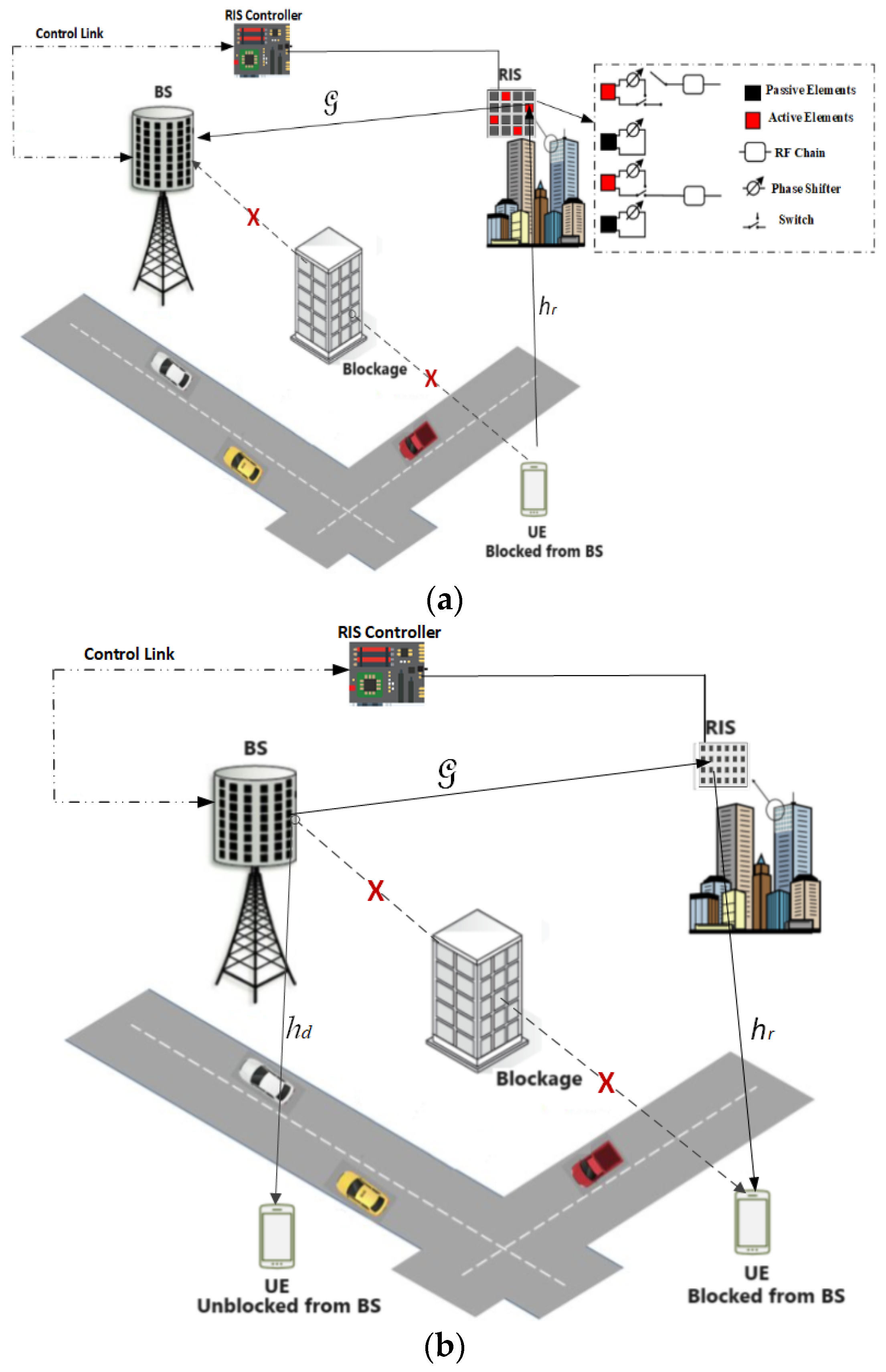
2.1. Uplink RIS-Aided mmWave Massive Mimo System Model

Figure 1a depicts the system model for the uplink RIS-aided mmWave massive MIMO wireless communication network. It comprises one user equipment (UE) that has its direct link to the base station (BS) blocked by obstructing objects. A hybrid passive/active RIS is employed to reflect the incident signals to the BS. Red and black colors, respectively, are used to denote the active and passive elements. The active elements of the RIS are sequentially connected to the R R I S receive RF chains via an antenna switching network, as shown in Figure 1a, whereas the passive elements induce phase shifts (controlled by an attached smart controller) to the incident signals and then reflect them. To acquire R R I S RIS measurements in each time slot, all R R I S RIS active elements are activated when the pilots are transmitted. The active components will function as the passive ones during the data transmission phase. Since the RIS is made up of small sub-wavelength patch elements with tunable reflection coefficients, the wave impinging on the RIS can be focused on a specific location in space or reflected in a desired direction by adjusting the reflection coefficients [4]. To solve the problem of dispersive channels, an orthogonal frequency division multiplexing (OFDM) transmission scheme with K subcarriers is employed. The BS analog and digital combiners are denoted as W R F C N B × R B and W B B , k C R B × N B , d , respectively, while the UE analog and digital precoders are denoted as F R F C N U E × R U E and F B B , k C N U E × N U E , d , respectively. The notations N B and R B are the numbers of BS’s antennas and radio frequency (RF) chains associated with the BS, respectively, and N U E and R B denote the number of antennas at the UE and the RF chains associated with the UE. The symbols N B , d and N U E , d represent the lengths of data streams at the BS and UE, respectively. For simplicity, single-user (with N U E = 1 ) as shown in Figure 1a is assumed, hence N B , d = N U E , d .
At the BS, the uplink received signal y k C N B , d × 1 at the k t h subcarrier can be written as
y k = W h r , k Θ G k F s k + n k ,
where 1 k K , W = W R F W B B , k H , F = F R F F B B , k , n k ~ C N 0 , σ n 2 I N B , d stands for the additive white Gaussian noise (AWGN), s k C N U E , d × 1 is the transmitted signal vector, h r , k C N R I S × 1 is the channel between the RIS and the UE at the k t h subcarrier, G k C N B × N R I S is the channel between the RIS and the BS at the k t h subcarrier, N R I S is the number of RIS’s reflecting elements, Θ = d i a g e j θ 1 , e j θ 2 , , e j θ N R I S , θ n R I S 0 , 2 π , the superscript . H is the conjugate transpose operator, and superscript . T denotes the transpose operator.
In a practical scenario, the RIS is always deployed on the walls of buildings [4] in the line-of-sight (LoS) directions to the BS, which is normally highly elevated with few obstructions in its vicinity [18]. After deployment, the positions of both the BS and the RIS remain unchanged. The prior knowledge of these positions can be used to estimate the LoS transmission’s directions between the BS and the RIS, that is, the LoS of the angle of arrival (AoA)/angle of departure (AoD) linking both, which remain static. The parameters can be sent to the UE through a control path by which G can be estimated through a one-step least square method. Further, in mmWave communication systems, the path loss for LoS is significantly lower than that for non-LoS (NLoS) paths. Hence, the NLoS path can be neglected since the LoS path will normally dominate the channel’s energy [19,20]. Based on the foregoing, without loss of generality, the channel G between the BS and the RIS is assumed to be known throughout this paper for simplicity’s sake and to avoid estimation of the cascaded channel. Consequently, the channel estimation problem reduces to an estimation of the time-varying channel link between the RIS and the UE, i.e., the h r , k . Assuming that the uplink pilot signals consist of N OFDM symbols or time slots, the received n t h OFDM symbol at the RIS associated with the k t h subcarrier, r n , k C N R I S ,   d × 1 , can be expressed as
r n , k = W R I S , n h r , k F n s n , k + w n , k ,
where W R I S , n C N R I S , d × N R I S is the RIS antenna selection matrix, N R I S , d is the length of data streams at the RIS, F n = F R F , n F B B , n , k , F B B , n , k is considered to be an identity matrix, F R F , n has phases of its elements following the mutually independent uniform distribution U 0 ,   2 π , s k C N U E , d × 1 is the transmitted signal vector, w n , k C N 0 ,   σ w 2 I N R I S , d is the AWGN, σ w 2 is the noise power, and s n , k C N U E , d × 1 is the n t h pilot symbol vector. Given that the RIS architecture is N R I S = N R I S , x × N R I S , y uniform planar array (UPA), the channel h r , k C N R I S × 1 can be written as [8,21]:
h r , k = d = 0 K 1 N R I S L l = 0 L 1 α l p d T s τ l a r φ l , ψ l e j 2 π k d K ,  
where
a r φ l , ψ l = 1 N R I S   e j 2 π m 1 u + m 2 v λ T ,  
m 1 = 0 ,   1 ,   2 ,   , N R I S , x 1   , and m 2 = 0 ,   1 ,   2 ,   , N R I S , y 1   , L  stands for the number of multipath components,  T s  is the sampling period,  p τ  is the pulse-shaping filter,  α l  is the complex gain of the  l t h  path,  τ l  is the discrete delay of the  l t h  multipath component,  φ l  is the azimuth AoA,  ψ l  is the elevation AoA,  u d s i n ψ l , v d s i n ψ l c o s φ l , d  is the antenna spacing that satisfies  d = λ / 2 , and λ  is the carrier signal’s wavelength. The steering vectors of AoAs can be collected into a matrix  A r as
A r = a r φ 1 , ψ 1 , a r φ 2 , ψ 2 , , a r φ L , ψ L C N R I S × L   .  
Vectorizing (2) results in
r n , k = F n s n , k T W R I S , n h r , k + w n , k = ψ n h r , k + w n , k ,
where ψ n = F n s n , k T W R I S , n is the n t h time slot measurement matrix, and F n = F R F , n F B B , n , k is the frequency-flat precoder. Though the assumption of frequency-flat could result in a high peak-to-average-power-ratio (PAPR), it could be relaxed by using a pseudo-random scrambling code [22]. Denoting R R I S as the number of RF chains related to the RIS, the total number of measurements is N T = N R R I S . Hence, the pilot overhead N can be reduced while increasing the number of RF chains R R I S at the expense of higher power consumption or reducing R R I S while increasing the pilot overhead N at the expense of wastage in bandwidth. By fixing R R I S = 1 , the total number of measurements, N T = N R R I S = N , and staking all the overall observations, measurement matrix, and noise vector r n , k , ψ n , and w n , k , respectively, for n = 1 ,   2 ,   ,   N as r k = r 1 , k T , r 2 , k T ,   ,   r N , k T T , ψ ¯ = ψ 1 T , ψ 2 T ,   ,   ψ N T T C N T × N R I S , w k = w 1 , k T , w 2 , k T ,   ,   w N , k T T , (6) can be written as:
r k = ψ ¯ h r , k + w k .  

2.2. Uplink RIS-UE Channel Sparsity Formulation

The goal is to estimate the RIS-UE channel h r , k in (7). However, this will require N T N R I S . Coincidentally, as a result of the angular-domain sparsity characteristic of the mmWave MIMO channel, the compressive sensing theory can be explored with the intent of reducing the pilot overhead N . Another challenge is related to the power leakage associated with the mismatch between AoAs and the discrete dictionary grids, that have limited resolution in the angular domain, which has the potential to weaken the inherent sparsity level. To circumvent this, a redundant dictionary can be designed as follows. The channel coefficients h r , k in (3) contained in the redundant dictionary can be written as
h r , k = A r , D h r s , k + w ˇ ,  
where w ˇ stands for the quantization error that can be treated as AWGN and A r , D has the following form
A r , D = a r φ 1 , ψ 1 ,   a r φ 1 , ψ 2 , , a r φ 1 , ψ ξ N R I S , y ,   a r φ 2 , ψ 1 ,   a r φ 2 , ψ 2 , , a r φ 2 , ψ ξ N R I S , y , , a r φ ξ N R I S , x , ψ ξ N R I S , y .  
The azimuth angle, φ i , and elevation angle, ψ i , are uniformly obtained from U π 2 ,   π 2 , and can be expressed as
φ i = π 2 + i π ξ N R I S , x ,   i = 1 , 2 , , ξ N R I S , x ,  
ψ i = π 2 + i π ξ N R I S , y ,   i = 1 , 2 , , ξ N R I S , y ,  
where the notation ξ represents the oversampling rate. In (8) h r s , k is an L ˇ -sparse channel of the angular domain that is represented by the redundant dictionary. To avoid weakening of the sparsity by the power leakage, the oversampling rate is set as ξ > 1 . By inserting (8) into (7), we obtain
r k = ψ ¯ v e c A r , D h r s , k + w ˇ + w k = ψ ¯ Ξ h r s , k + w e ,  
where w e = ψ ¯ v e c w ˇ + w k stands for the effective noise, Ξ = 1 A r , D represents the redundant dictionary matrix, and h r s , k represents the sparse channel formulation under the redundant dictionary basis. The angular domain channels h r s , k , k = 1 , 2 , , K possess common sparsity due to the similarity of scatterers of subchannels associated with different subcarriers. Thus, the support set of h r s , k , ζ = s u p p h r s , k , is such that
ζ = s u p p h r s , 1 = s u p p h r s , 2 , , = s u p p h r s , K .  
The channel estimation techniques based on CS algorithms presented in Section 3 can be used to solve the following optimization problem of the sparse channel, given the observation measurement in (11)
min h rs , k optimum , 1 k K h r s , k 0  
s . t .   ψ ¯ Ξ h r s , k r k 2 ϵ ,   f o r   a l l   k   a n d   s u p p o r t   s e t   ζ ,
where ϵ is the stopping criterion threshold.

2.3. Downlink RIS-Aided mmWave Massive Mimo System Model

For the downlink scenario, Figure 1b, which comprises one BS and one RIS that provided virtual LoS to the user when the direct LoS to the BS is obstructed by any obstacles, is considered. Both the BS and RIS are assumed to be made up of uniform planar arrays (UPAs), having the antennas’ number given as N B = N B , x × N B , y and N R I S = N R I S , x × N R I S , y , respectively. The UEs in the network are also assumed to be made of a single antenna each, N U E = 1 . Further, it is also assumed that the base station is equipped with R B N B RF chains for the considered hybrid mmWave massive MIMO architecture and each of them is connected via N B phase shifters to N B antennas. Similarly to the uplink scenario, the OFDM transmission scheme with K subcarriers and T s sampling period is employed. Denoting h d , k C N B × 1 and h r , k C N R I S × 1 as the direct channels between the BS and the UE, and between the RIS and the UE at the k t h subcarrier, respectively, these two can be modelled similarly as h r , k in (3) for uplink scenario. The channel between the RIS and the BS at the k t h subcarrier is denoted as G k C N B × N R I S , and can be modeled as follows. The BS-to-RIS channel G k at the k t h subcarrier can be modeled as
G k = G L o S , k + G N L o S , k ,
where G L o S , k C N B × N R I S and G N L o S , k C N B × N R I S are the LoS and NLoS parts of the frequency-domain channel G k . By treating each of the subchannels G L o S , k and G N L o S , k as a flat fading channel, the narrow-band channel modeling techniques described in [23,24] can be employed to model them as
G L o S , k = d = 0 K 1 α 0 γ 0 p d T s τ 0 a r φ 0 , ψ 0 a t H φ 0 , ψ 0 e j 2 π k d K ,  
G N L o S , k = d = 0 K 1 l = 1 L α l γ l p d T s τ l a r φ l , ψ l a t H φ l , ψ l e j 2 π k d K ,  
where γ l and α l stand for large-scale fading coefficient and complex gain associated with the l t h path, respectively, while l = 0 for LoS and l > 0 for NLoS. The UPA steering vector a r φ l , ψ l C N R I S × 1 for RIS is as previously defined in (4), while the UPA steering vector a t φ l , ψ l C N B × 1 for the BS equipped with N B = N B , x × N B , y uniform planar array is similarly given as
a t φ l , ψ l = 1 N B   e j 2 π n 1 u + n 2 v λ T ,  
n 1 = 0 , 1 , 2 , , N B , x 1 , and n 2 = 0 , 1 , 2 , , N B , y 1 , u d s i n ψ l , v d s i n ψ l c o s φ l , d is the antenna spacing that satisfies d = λ / 2 , and other parameters are as previously defined.
Given x n , k C N B × 1 , the n t h transmitted pilot symbol vector at the k t h subcarrier, the n t h -time slot received signal by the user at the k t h subcarrier can be written as
y n , k = h d , k T x n , k + h r , k T Θ n G k x n , k + w n , k = h d , k T ,   h r , k T x n , k Θ n G k x n , k + w n , k ,  
where w n , k ~ C N 0 ,   σ w 2 is the AWGN, Θ n = d i a g e j θ n , 1 ,   e j θ n , 2 ,   ,   e j θ n , N R I S , θ n   n S 0 ,   2 π , stands for the phase compensation, which is assumed to be perfectly known in this paper, introduced by the RIS to the signals. By stacking all y n , k and w n , k for n = 1 ,   2 ,   ,   N as y k = y 1 , k , y 2 , k ,   ,   y N , k T and w k = w 1 , k , w 2 , k ,   ,   y N , k T , respectively, (18) can be written as
y k T = h d , k T ,   h r , k T x 1 , k x 2 , k   x N , k Θ 1 G k x 1 , k Θ 2 G k x 2 , k Θ N G k x N , k + w k .
From (14), G k is said to have both LoS and NLoS components. It is further stated in Section 2.1 that the path loss for LoS is significantly lower than that for non-LoS (NLoS) paths. Consequently, the NLoS can be neglected since the LoS path will normally dominate the channel’s energy. Hinged on these facts, assuming a priori knowledge of RIS, the substitution of (14) into (19) while taking the items associated with the NLoS component of G k as noise results in (19) assuming the following form
y k T = h d , k T ,   h r , k T x 1 , k x 2 , k   x N , k Θ 1 G L o S , k x 1 , k Θ 2 G L o S , k x 2 , k Θ N G L o S , k x N , k + h r , k T Θ 1 G N L o S , k x 1 , k ,   Θ 2 G N L o S , k x 1 , k , ,   Θ N G N L o S , k x 1 , k + w k .
By denoting h e f f , k = h d , k T ,   h r , k T T C N B + N R I S × 1 as the effective channel vector of the users and Ω k , the measurement matrix, as
Ω k = x 1 , k x 2 , k   x N , k Θ 1 G k x 1 , k Θ 2 G k x 2 , k Θ N G k x N , k T C N × N B + N R I S ,
and writing n k , the effective measurement noise vector as
n k = h r , k T Θ 1 G N L o S , k x 1 , k ,   Θ 2 G N L o S , k x 1 , k , ,   Θ N G N L o S , k x 1 , k + w k ,
the aggregate received pilot signal of (20) can be re-written as
y k = Ω k h e f f , k + n k .

2.4. RIS-Supported Downlink Sparsity Formulation

The system represented by (23) is an under-determined system due to the mmWave massive MIMO requiring N B + N R I S > N consequent upon the antenna arrays’ large dimension and the constrained channel coherent time. Similarly to Section 2.2, by taking advantage of the angular-domain sparsity characteristic of the mmWave MIMO channel, the under-determined problem of (23) can be solved using CS theory. Considering the virtual angular domain representation, redundant dictionaries can be designed to make both channel coefficients h d , k T and h r , k T (that forms the effective channel h e f f , k in (23)) to be written in the same way as (8), thereby assuming the following forms
h d , k T = h s d , k T A d , D H + n e d , k T ,
h r , k T = h s r , k T A r , D H + n e r , k T ,
where A d , D and A r , D are redundant dictionaries, with A r , D having the form given in (9), and A d , D having the following form
A d , D = a r φ 1 , ψ 1 ,   a r φ 1 , ψ 2 , , a r φ 1 , ψ η N B , y ,   a r φ 2 , ψ 1 ,   a r φ 2 , ψ 2 , , a r φ 2 , ψ η N B , y , , a r φ η N B , x , ψ η N B , y .
Both φ i and ψ i which are uniformly obtained from U π 2 ,   π 2 can be expressed as
φ i = π 2 + i π η N B , x ,   i = 1 , 2 , , η N B , x ,
ψ i = π 2 + i π η N B , y ,   i = 1 , 2 , , η N B , y ,
where the notation η > 1 stands for the oversampling rate. In (24) and (25) both n e d , k and n e r , k are the quantization error vectors due to mismatches between the actual angles and the samples in A d , D and A r , D , respectively, while h s d , k and h s r , k are representations of both h d , k and h r , k in virtual angular domains, respectively. Because of the angular sparsity of the mmWave channel, both h s d , k and h s r , k are sparse quantities. Substitution of (24) and (25) into (23) results in
y k = Ω k h d , k T ,   h r , k T T + n k = Ω k h s d , k T A d , D H ,   h s r , k T A r , D H T + n e d , k T ,   n e r , k T T + n k = Ω k A d , D H A r , D H T h s d , k T ,   h s r , k T T + Ω k n e d , k T ,   n e r , k T T + n k .
By denoting Υ , the effective dictionary matrix as Υ = A d , D H A r , D H T , n e f t , k = Ω k n e d , k T , n e r , k T T + n k as the effective noise vector, and h e f t , k = h s d , k T , h s r , k T T , the effective sparse channel vector to be reconstructed, (28) can be re-written concisely as
y k = Ω k Υ h e f t , k + n e f t , k .
As previously alluded to, due to the unchanged nature of the spatial propagation properties of the channel, the angular domain channels possess common sparsity at different subcarriers such that the support set of h e f t , k , J = s u p p h e f t , k can be written as
J = s u p p h e f t , 1 = s u p p h e f t , 2 , , = s u p p h e f t , K .
Given the observation measurement in (29), the effective sparse channel h e f t , k can be reconstructed using the channel estimation techniques presented in Section 3. This can be achieved by applying the estimators to solve the following optimization problem
min h eft , k optimum , 1 k K h e f t , k 0
s . t . Ω k Υ h e f t , k y k 2 ε ,   f o r   a l l   k   a n d   s u p p o r t   s e t   J ,
with ε being the stopping criterion threshold.

3. The Compressive Sensing-Based Channel Estimation Schemes

This section presents the two CS-based channel estimation schemes proposed to estimate the uplink and downlink channels of the RIS-aided mmWave massive MIMO systems, respectively. The proposed schemes are pilot-assisted based schemes and perform channel estimations when pilot signals are transmitted. One of the proposed channel estimation schemes, the AdptSOMP, needs prior knowledge of the initial support set, while the other, the StrMP, estimates it. The last subsection presents the comparative computational complexity costs of the channel estimation techniques.

3.1. Adaptive SOMP(AdptSOMP)-Based Channel Estimation Scheme for the Uplink Channel

The AdptSOMP-based channel estimation works in a similar way as the distributed orthogonal matching pursuit (DOMP)-based channel estimator [12] by tracking dynamic sparse channels sequentially. The final channel estimates are obtained by updating the small variation of the dynamic sparse channel. The fundamental concept of the AdptSOMP-based channel estimation is that, because of the temporal correlations of the dynamic sparse channel, the major information of the channel in the current time slot can be obtained from the estimation results in previous time slots. The small variation of the channel can then be estimated with low complexity to refine the final estimate result. This is fundamentally different from the conventional OMP-based channel estimation, which disregards any channel tap temporal connection. With the availability of the observation measurements r k , the sensing matrices ψ ¯ Ξ that comprise the measurement matrix ψ ¯ and redundant dictionary Ξ = 1 A r , D , and the initial sparsity level L ˇ , the proposed AdptSOMP, that is based on the traditional SOMP algorithm, estimate the uplink sparse channel as described in Algorithm 1. In Step 1, the iteration i, the support set ζ, and the residual vector signal r are all initialized. The initial support set is computed in Step 2. Step 3 focuses on the computation of the updated support set via the union of the initial estimate computed in Step 2. The sparse signal h ^ is estimated via the least square (LS) criterion in Step 4, while the residual signal is computed in Step 5. The enhanced sparse level is computed based on the concept of sparsity estimation from [25,26] in Step 6. The stopping criterion condition is determined if it is satisfied in Step 7, and the enhanced sparse signal h ^ is finally estimated in Step 9.
Algorithm 1 The AdptSOMP-based Channel Estimation Scheme for Uplink RIS-Aided mmWave Massive MIMO System
Input: Observation measurements r k , sensing matrices ψ ¯ Ξ   ,   N R I S , the power threshold for determining the active paths  p t h = 0.1  [11], number of multipath components  L , redundant dictionary  A r , D , and the stopping criterion threshold  ϵ .
Output: Reconstructed sparse channel  h ^ r , k
Initialization:
  1.
i = 1 , and ζ ^ i = 1 = , and r k i = 1 = r k .
Iteration:
    for  i = i + 1  do
  2.
^ i , o p t max k = 1 K ψ ¯ Ξ H r k i
  3.
ζ ^ i ζ ^ i 1 ^ i , o p t
  4.
h ^ k i ψ ¯ Ξ ζ ^ i r k ; where . denotes the Moore-Penrose pseudo-inverse.
  5.
r k i r k ψ ¯ Ξ ζ ^ i h ^ k i
  6.
D h = l : n = 1 N R I S h ^ n , l i 2 p t h l = 0 L 1 ,
L = D h 0 ,
where D h 0  stands for the number of nonzero elements in D h . The estimation of the sparsity level update is based on the knowledge that the input to the AdptSOMP can vary with varying channel conditions, which, in turn, could alter the sparsity level. Thus, AdptSOMP is adaptive to the channel sparsity level   L . In addition, AdptSOMP roughly considers the temporal correlations of the dynamic sparse channel.
  7.
if   r k i 2 > ϵ   & &   i > L .
  8.
Return  h ^ r s , k h ^ k i , or else repeat iterations.
end for
  9.
h ^ r , k = A r , D h ^ r s , k .

3.2. Adaptive SOMP(AdptSOMP)-Based Channel Estimation Scheme for the Downlink Channel

The summary of the AdptSOMP-based channel estimation technique described in the previous subsection as used for the reconstruction of downlink channels between the BS and UE, and between the RIS and UE is presented in Algorithm 2. Its procedure is similar to the one for the uplink channel except that it uses an effective dictionary matrix Υ in Step 2 to compute the initial support set. Then, in Step 14, there is the decomposition of effective channels to the virtual angular domain representations, h s d , k and h s r , k , of the channels of interest. Finally, the estimates of the direct channels from BS-to-UE and from RIS-to-UE h ^ d , k and h ^ r , k , respectively, are obtained in Steps 14 and 16.
Algorithm 2 The AdptSOMP-based Channel Estimation Scheme for Downlink RIS-Aided mmWave Massive MIMO System
Input: Observation measurements  y k , the measurements matrix  Ω k ,the effective dictionary matrix  Υ N R I S , the power threshold for determining the active paths  p t h = 0.1  [25], the number of multipath components  L , redundant matrices  A d , D  and  A r , D , and the stopping criterion threshold  ϵ .
Output: Estimated channel vectors  h d , k  and  h r , k .
Initialization:
   J 1          Iteration counter
    r r e s , k j = 1 y k           Residual error vector at  j t h  iteration
    J ^ j = 1             Support set at the  j t h  iteration
Iteration:
  1.
J J + 1
  2.
^ j , o p t max k = 1 K Ω k Υ H y k j
  3.
ζ ^ j ζ ^ j 1 ^ j , o p t
  4.
h ^ k j Ω k Υ ζ ^ j y k , where  .  is the Moore–Penrose pseudo-inverse.
  5.
r r e s , k j y k Ω k Υ ζ ^ j h ^ k j
  6.
S h = l : n = 1 N R I S h ^ n , l j 2 p t h l = 0 L 1
  7.
L = S h 0
Ending Criterion:
  8.
If   r r e s , k j 2 > ϵ & & j > L
  9.
exit the iteration, or else go to step 1.
  10.
h ^ k h ^ k j
  11.
ζ ^ ζ ^ j
  12.
return  h ^ k j   ,   ζ ^
Decomposition and Computation of the final CSI
  13.
h ^ e f t , k ζ ^ h ^ k
  14.
h ^ s d , k T , h ^ s r , k T T h ^ e f t , k
  15.
h ^ d , k T h ^ s d , k T A d , D H
  16.
h ^ r , k T h ^ s r , k T A r , D H

3.3. Structured Matching Pursuit (StrMP)-Based Channel Estimation Scheme for the Uplink Channel

The StrMP-based channel estimation tracks the dynamic channel taps to improve the final reconstruction. In each iteration, an unreliable channel tap, which is subtracted from a dependable one, is added to the estimated support set. In summary, the StrMP-based channel estimation possesses the capability to detect the common channel taps accurately and track the dynamic channel taps rapidly. Given the observation measurements r k , the sensing matrices ψ ¯ Ξ that comprise the measurement matrix ψ ¯ and redundant dictionary Ξ = 1 A r , D , and the maximum sparsity level L , the StrMP-based channel estimation technique estimates the uplink RIS-aided mmWave massive MIMO channel through the following procedure. The knowledge of the maximum sparsity level L is based on the general knowledge of the sparsity level made possible by some works, such as the one reported in [27], which gives a sense of the mmWave channel’s sparsity level.
The StrMP-based channel estimation scheme’s estimation procedure for the uplink channel is presented in Algorithm 3 and entails two stages. Stage A focuses on the computation of the support set through iterative selection of the element that matches best with the residual vector signals while employing ζ ^ 0 = to initialize the procedure. The StrMP-based channel estimation scheme assumes that the elements of the support set between any two time slots are constrained by the difference between the initial sparsity level and maximum sparsity level: L ˇ L [28], that is
ζ ^ n \ ζ ^ k < L ˇ L , n k .  
Under Stage A, Step 1 focuses on the initialization of the support set ζ and the residual vector signal r k . Steps 2 and 3 concentrate on the iteration process for the estimation of the initial support set and the retuning of the estimated initial support set, respectively. Step 1 of Stage B initializes the iteration i , the support set ζ , and the residual vector signal r . Step 2 focuses on the iteration selection stage to estimate the temporal sparse signal h ¯ k . Steps 3 and 4 involve the termination step, estimation, and return of the sparse channel h ^ r s , k with the aid of the estimated support set and the estimation of the sparse uplink channel h ^ r , k , respectively.
Algorithm 3 The StrMP-based Channel Estimation Scheme for Uplink RIS-Aided mmWave Massive MIMO System
Input: The Observation measurements  r k , the sensing matrices  ψ ¯ Ξ N R I S , redundant dictionary  A r , D , the stopping criterion threshold  ϵ , and the maximum sparsity level possible  L .
Output: Reconstructed sparse channel  h ^ r , k
Stage A: Computation of the Initial Support Set
1.
ζ ^ 0 = , and r r e s = r k .
2.
Iteration selection stage
   for l = 1   t o   L  do
P = ψ ¯ Ξ H r r e s
ϱ n arg max n k = 1 K p n , k ,       n = 1 , 2 , ,   N
ζ ^ 0 ζ ^ 0 ϱ n
r r e s r k ψ ¯ Ξ ζ ^ 0 ψ ¯ Ξ ζ ^ 0 r k ,
  end for
3.
Return  ζ ^ 0  to be used in Stage 2
Stage BEstimation of the sparse signal  h ^ k
  1.
i = 1 , and  ζ ^ i = 1 = ζ ^ 0 h ^ k = ψ ¯ Ξ ζ ^ 0 r k , and  r k i = 1 = r k ψ ¯ Ξ h ^ k
  2.
Iteration selection stage to estimate the temporal sparse signal  h ¯ k
  while  i = 1   o r   r k i 2 > ϵ    do
i = i + 1 ,
ϱ j arg max j ψ ¯ Ξ j H r k i 1
ζ ^ i ζ ^ i 1 ϱ j
h ¯ k = ψ ¯ Ξ ζ ^ i r k
ζ ^ i s u p p h ¯ k ,   L ,
where  s u p p ( z , k )  denotes the set of indices that matches the  k  largest amplitude components of  z .
r k i r k ψ ¯ Ξ ζ ^ i ψ ¯ Ξ ζ ^ i r k
   end while
  3.
ζ ^ = ζ ^ i 1 h ^ k = ψ ¯ Ξ ζ ^ r k
  Return  h ^ r s , k h ^ k i .
  4.
h ^ r , k = A r , D h ^ r s , k . .

3.4. Structured Matching Pursuit (StrMP)-Based Channel Estimation Scheme for the Downlink Channel

This subsection summarizes the proposed StrMP-based channel estimation scheme as used for the estimation of the downlink channels between BS and UE and between the RIS and UE. With the availability of the observation measurements y k , the measurement matrix Ω k , the effective dictionary matrix Υ , the initial sparsity level L ˇ , and the maximum sparsity level possible L , the various steps employed by the proposed StrMP-based channel estimation technique to reconstruct both h d , k and h r , k are presented in Algorithm 4. The StrMP-based channel estimation scheme’s estimation procedure entails three stages. In Stage 1, the initial support set is estimated for use in Stage 2 instead of initializing it to an empty set.
Algorithm 4 The StrMP-based Channel Estimation Scheme for Downlink RIS-Aided mmWave Massive MIMO System
Input: Observation measurements  y k , the measurements matrix  Ω k , the effective dictionary matrix  Υ N R I S , the number of multipath components  L , redundant matrices  A d , D  and  A r , D , maximum sparsity level  L , and the stopping criterion threshold  ϵ .
Output: Estimated channel vectors  h d , k  and  h r , k .
Stage 1: Initial support set estimation
Initialization:
   r r e s y k             Residual error vector
   J ^ 0               Support set at the  j t h  iteration
Iteration:
for  l = 1   t o   L  do
  1.
P = Ω k Υ H r r e s
  2.
ϱ n arg max n k = 1 K p n . k ,   n = 1 , 2 , , N
  3.
J ^ 0 J ^ 0 ϱ n
  4.
r r e s y k Ω k Υ J ^ 0 Ω k Υ J ^ 0 y k
end for
  5.
return  J ^ 0

Stage 2: Estimation of the temporal sparse signal  h ¯ k
Initialization:
   J 1                 Iteration counter
   h ^ k Ω k Υ J ^ 0 y k               Initial estimation of the sparse signals
   r r e s , k j = 1 y k Ω k Υ h ^ k           Residual error vector at the j t h  iteration
   J ^ j = 1 J ^ 0              Support set at the  j t h  iteration
while  j = 1     o r     r r e s , k j 2 > ϵ  do
  6.
J J + 1
  7.
ϱ i arg max i Ω k Υ i H r r e s , k j = 1
  8.
J ~ j J ^ j 1 ϱ i
  9.
h ¯ k Ω k Υ J ~ j y k
  10.
J ^ j s u p p h ¯ k , L
  11.
r r e s , k j y k Ω k Υ J ^ j Ω k Υ J ^ j y k
end while
  12.
J ^ J ^ j
  13.
h ^ k Ω k Υ J ^ y k
  14.
return  h ^ k J ^

Stage 3Decomposition and Computation of the final CSI
  15.
h ^ e f t , k J ^ h ^ k
  16.
h ^ s d , k T , h ^ s r , k T T h ^ e f t , k
  17.
h ^ d , k T h ^ s d , k T A d , D H
  18.
h ^ r , k T h ^ s r , k T A r , D H .

3.5. Comparative Computational Complexity Costs of the Proposed Estimator

In this subsection, the computational complexity costs of the proposed channel estimators in terms of the number of complex multiplication/division that are required are presented. The case of the uplink channel estimation for the RIS-aided mmWave Massive MIMO system illustrated in Figure 1a is considered. The extension to the downlink scenario is straightforward. By considering Section 3.1, the proposed AdptSOMP-based channel estimator requires for Steps 2, 4, 5, and 6 the following orders of computational complexity: O K N N R I S 2 , O N N R I S 2 , O N L 2 , and O L 2 , respectively. This gives the total computational complexity cost required by the AdptSOMP-based channel estimator as O N L 2 + N R I S 2 + K N R I S 2 + L . The proposed StrMP-based channel estimator in Section 3.3 requires for Stage A (Step 2) the computational complexity orders of O L N N R I S 2 + N 3 L , while it requires for Stage B (Step 1) the computational complexity orders of O N N R I S 2 + L N R I S 2 , and for Stage B (Step 2) the computational complexity orders of O 2 N N R I S 2 + N 2 N R I S 2 , respectively. Hence, the StrMP-based channel estimator requires a total computational complexity order of O N L N R I S 2 + N 2 L + 3 N R I S 2 + N N R I S 2 + N R I S 2 L . Both the OMP and the DOMP [12] require total computational complexity orders of O 2 L N N R I S 2 , and O N L 2 + N R I S 2 + K N R I S 2 , respectively. Numerical computational complexity costs of these channel estimation schemes based on some fixed parameters are presented in Table 1 to give an idea of the comparative complexity costs of these estimators. From Table 1, it is obvious that the poorly performing estimator, the OMP-based channel estimator, incurs the least computational complexity cost, while the proposed AdptSOMP and DOMP, as revealed in the next section, show similar performance incurred almost the same computational complexity costs.
The proposed StrMP-based channel estimator that, as illustrated in the next section, exhibits the best performance incurred a slightly higher computational complexity cost compared with the two closely performing estimators, i.e., the AdptSOMP and the DOMP-based channel estimators.

4. Simulation Results and Discussion

This section presents the computer simulation results for the two systems described in Section 2 to document the achievable comparative performances of the proposed CS-based channel estimation schemes. The section is divided into three subsections. Section 4.1 focuses on the simulation results for the uplink RIS-aided mmWave Massive MIMO wireless communication systems, whereas Section 4.2 focuses on the simulation results for the downlink RIS-aided mmWave Massive MIMO wireless communication systems.

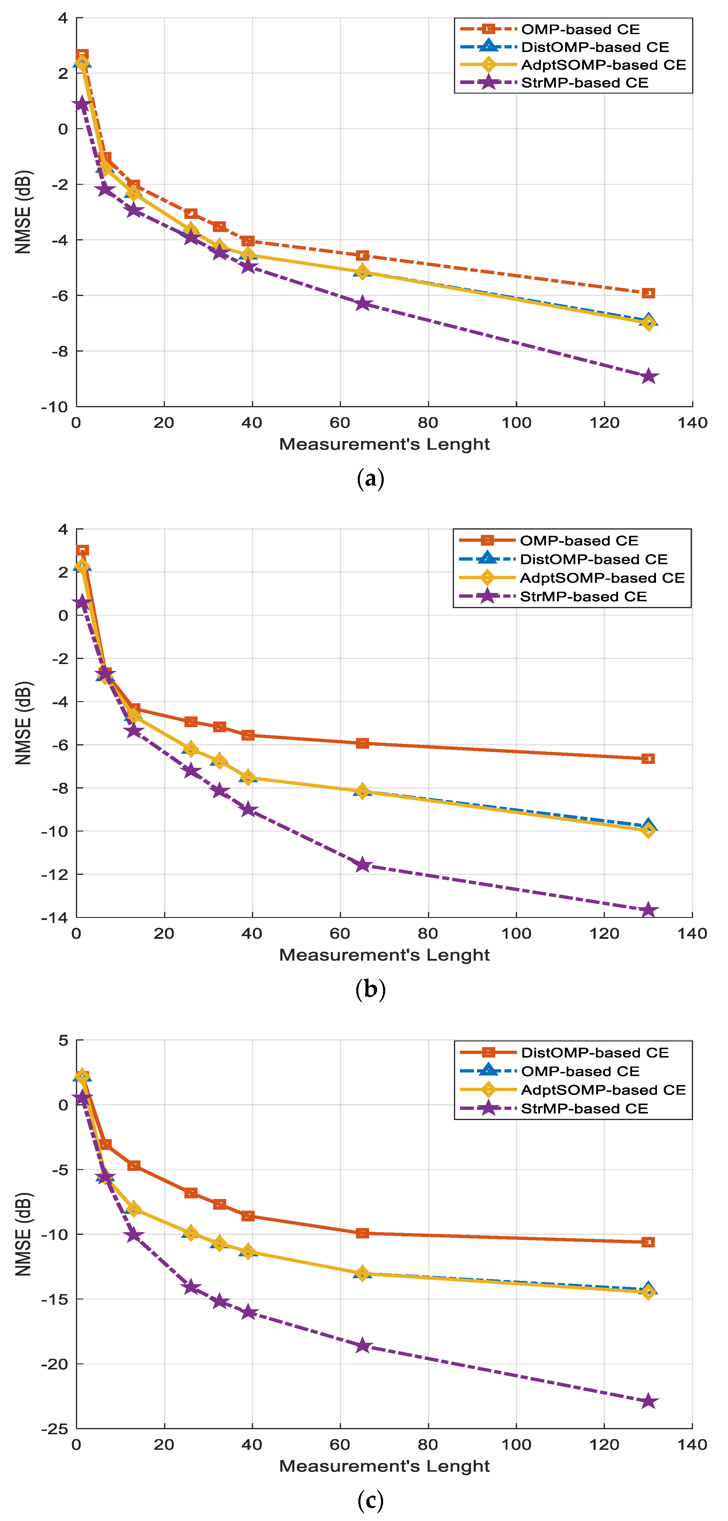
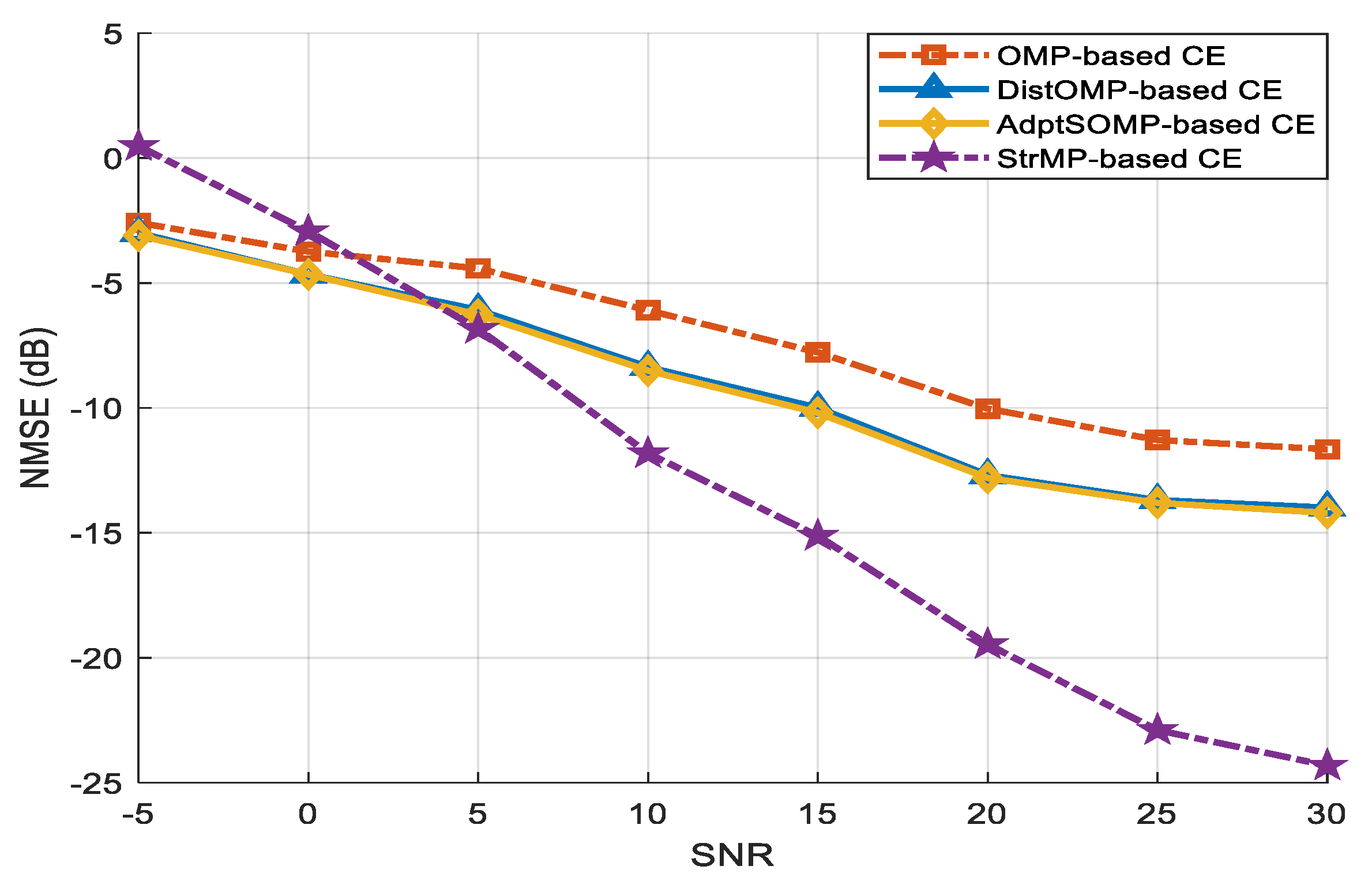
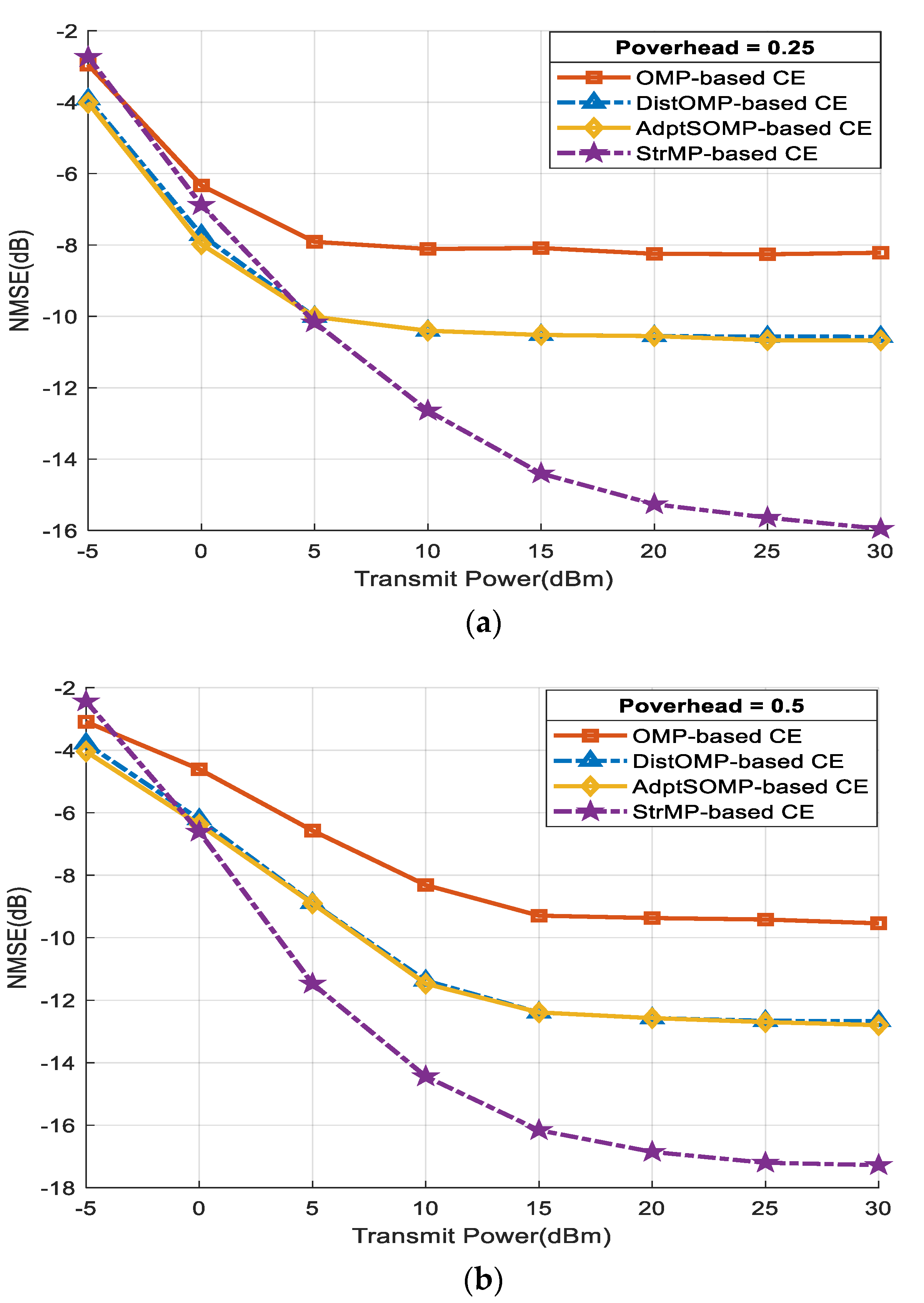
4.1. Simulation Results for the Uplink RIS-Aided mmWave Massive Mimo System Model

For the simulation of the Uplink system of Figure 1a, a RIS architecture with N R I S = N R I S , x × N R I S , y = 16 × 16 UPA, and R R I S = 1 RF chain, N U E = 1 antenna, carrier frequency of 28 GHz and bandwidth of 100 MHz are assumed. With R R I S = 1 , the total number of measurements (measurement length), N T = N R R I S = N . Other parameters are set as follows. The number of OFDM subcarriers is set as 256 , while the number of multipath L is set as 6 , and the initial sparsity level L ˇ = 3 is assumed. Both the AoD and AoA are uniformly obtained from U π 2 ,   π 2 . The stopping criterion parameter ϵ for both AdptSOMP-based estimator and StrMP-based estimator is set as ϵ = σ w 2 . The performances of the estimators are obtained in terms of the normalized mean square error (NMSE) metric expressed as
N M S E = E H H ^ F 2 / H F 2 ,  
where E . represents the expectation operation.
The first set of results shown in Figure 2a–c seeks to investigate the comparative NMSE performances of the proposed estimators and the other two benchmark estimators considered in this paper, namely, the distributed orthogonal matching pursuit (DOMP)-based channel estimator [12], and the traditional OMP-based estimator, for different values of signal-to-noise ratio (SNR). The increase in the measurement length ensures better observation, which results in enhanced NMSE, as depicted in Figure 2a–c. Of all the considered channel estimation schemes, as expected, the OMP-based estimator displays the poorest performance for the three SNR values of 5   d B , 10   d B , and 20   d B . The proposed AdptSOMP-based estimator displays performance that is similar to the performance of the DOMP-based estimator, while the proposed StrMP-based estimator outperforms all other three estimators, especially for measurement length values of N = 40 ,   12 , and 8 for SNR of 5   d B , 10   d B , and 20   d B , respectively. As N T increases, the performance of each of the estimators increases. As stated in Section 2.1, the pilot overhead N can be reduced while increasing the number of RF chains R R I S at the cost of higher power consumption. Alternatively, the R R I S can be reduced while increasing N resulting in a wastage of bandwidth. With R R I S fixed at R R I S = 1 , a reduced overhead can be considered as a tradeoff between performance and complexity (that will result in higher power consumption). Since the pilot overhead is directly proportional to the measurement length, the results shown in Figure 2 suggest that the proposed StrMP-based estimator can attain, at a reduced pilot overhead, the performances exhibited by the other estimators at higher pilot overhead.
Considering the results in Figure 2, we opted for the value of N = 64 , beyond which the performances of most of the estimators (except the proposed StrMP-based estimator) do not improve significantly. Using N = 64 , Figure 3 depicts the NMSE performances of the estimators as SNR increases. Between the SNR range of 5   d B and 1.5   d B , the OMP-based estimator’s performance is better than that of the StrMP-based estimator but lags behind both the AdptSOMP-based estimator and DOMP-based estimator, which exhibits better performance than the StrMP-based estimator up to the SNR value of 4   d B . Beyond the SNR of 1.5   d B and 4   d B , the proposed StrMP-based estimator outperforms OMP and both AdptSOMP and DOMP. Both AdptSOMP and DOMP perform almost equally through the range of the SNR considered. Specifically, at NMSE (dB) of 10 , the proposed StrMP-based estimator performs better than the OMP-based estimator by about 12   d B and outperforms both the DOMP-based estimator and the second proposed AdptSOMP-based estimator by about 7   d B . Both the proposed AdptSOMP-based estimator and DOMP-based channel estimator [12] outperform the OMP-based estimator because they both roughly consider the temporal correlations of the dynamic sparse channel, as explained in Section 3.1. The proposed StrMP-based estimator exhibits a better performance than all three other estimators because of its capability to detect the common channel taps accurately and track the dynamic channel taps rapidly, as alluded to in Section 3.3. The proposed StrMP-based channel estimation scheme, however, exhibits poor performance starting from SNR of 4 dB to lower values of SNR. This could be attributed to the pronouncement of noise power that might have affected its sensitivity to detect the common channel taps accurately and track the dynamic channel. This will warrant employing higher pilot overhead to improve its performance at the lower SNR regime.

4.2. Simulation Results for the Downlink RIS-Aided mmWave Massive MIMO System Model

In this sub-section, the RIS-aided mmWave massive MIMO system illustrated in Figure 1b is simulated to benchmark the performance of the proposed channel estimator for the downlink scenario. For this system, the bandwidth of 100 MHz is maintained while assuming the carrier frequency of 30 GHz, N B = N B , x × N B , y = 16 × 16 , and N R I S = N R I S , x × N R I S , y = 16 × 16 , number of subcarriers K = 64 , R B = 1 RF chain, number of paths L = 6 , and initial sparsity-level L ˇ = 3 . The parameter ϵ = σ w 2 is employed for all the estimators, and σ w 2 is empirically obtained from the noise power spectrum density set as 174   d B m / H z [12] at the user equipment point. Assuming that both the blocked and unblocked users communicate with the BS and RIS via only NLoS paths, respectively, the pilot overhead (Poverhead) evaluation of the channel estimators can be expressed as
P o v e r h e a d = N / N B + N R I S .  
Results in Figure 4a,b are the NMSE performances versus the transmit power for the estimation of the blocked user’s channel, h r , k , when the pilot overheads are set to 0.25 and 0.5 , respectively. In this case, the signal from h d , k is treated as noise. At the instance, when the pilot overhead is set as 0.25 , the proposed AdptSOMP-based estimator and the DOMP-based estimator outperform the proposed StrMP-based estimator between the transmit power range of 5   d B m and 5   d B m . Beyond this SNR point, the proposed StrMP-based estimator outperforms all the other estimators with significant margins. When the pilot overhead is increased to 0.5 , the proposed StrMP-based estimator exhibits better performance than the other estimators, right from the transmit power value of 0   d B m to higher values of the transmit power. At NMSE (dB) of 8 , the proposed StrMP-based estimator outperforms the OMP-based estimator by about 8   d B m , and outperforms both the DOMP-based estimator and the second proposed AdptSOMP-based estimator by about 2.8   d B m . The results in Figure 4b indicate that the proposed AdptSOMP-based estimator shows some level of robustness, from the transmit power value of 0   d B m upward, against possible interference from the BS-to-RIS’s channel NLoS paths (though characterized with larger path loss in comparison with that of the LoS path) and the associated additive noise. Figure 5a,b depict the NMSE performances versus the transmit power for the estimation of the unblocked user’s channel, h d , k , with the pilot overheads set to 0.25 and 0.5 , respectively. The signal from h r , k is equally treated as noise. The two results show a strong departure from those of Figure 4a,b in that up to 5   d B m and 3   d B m , the proposed AdptSOMP-based estimator and DOMP-based estimator show improved performance and evidence of resilience to interference from the BS-to-RIS’s channel NLoS paths and additive noise while estimating h d , k when compared with the proposed StrMP-based estimator for the case of pilot overhead values of 0.25 and 0.5 , respectively. The performance of the proposed StrMP-based estimator only begins to show improved performance compared with the two closely performing estimators, the proposed AdptSOMP-based estimator and the DOMP-based estimator, from 5   d B m and 3   d B m and beyond for the pilot overhead values of 0.25 and 0.5 , respectively. By considering Figure 4a,b, from the transmit power of 5 dBm and higher, the performance of the proposed StrMP-based estimator with reduced pilot overhead of 0.25 in Figure 4a is better than the performances of the other estimators with higher pilot overhead of 0.5 in Figure 4b. Similarly, by considering Figure 5a,b, from the transmit power of 8 dBm and higher, the performance of the proposed StrMP-based estimator with the reduced pilot overhead of 0.25 in Figure 5a is better than all performances of the other estimators with a higher pilot overhead of 0.5 in Figure 5b. Unlike all the other three estimators, the proposed StrMP-based estimator exhibits significant improvement in performance as the transmit power increases up to 25   d B m , while the performances of the other three estimators cease to show any improvement beyond the transmit power of 10   d B m . This figure shows that the proposed StrMP-based estimator benefits from the increase in transmit power in estimating h d , k and simultaneously shows resilience to both the interference from the BS-to-RIS’s channel NLoS paths and additive noise. In addition, as suggested in Section 4.1, the proposed StrMP-based estimator also benefits from its capability to detect the common channel taps accurately and track the dynamic channel taps rapidly, as alluded to in Section 3.3.

5. Conclusions

In this paper, two channel estimation techniques, based on SOMP and matching pursuit algorithms, are presented for uplink and downlink channels’ estimations in RIS-aided mmWave massive MIMO wireless communication systems. These were presented for one user in an uplink scenario and two users in a downlink scenario. Through computer simulation, the performances of the proposed estimators were investigated, and the comparative computational complexity costs of the proposed channel estimation schemes were analyzed. For the uplink channel scenario, one of the proposed estimators, the StrMP-based channel estimator, outperforms the two benchmark estimators. When optimum pilot overhead was employed, it was found that the proposed StrMP-based channel estimator performance exceeded others from the SNR value of 5 dB. In the downlink channels scenario, the proposed StrMP-based channel estimator’s performance only exceeds others from the 5 dB SNR for a lower overhead value of 0.25 and shows better performance from the SNR lower than 5 dB when the pilot overhead is increased to 0.5. The second proposed estimator, the AdptSOMP-based channel estimator exhibits performance similar to that of DOMP that incurred similar computational complexity costs with each other [12]. The better performance of the StrMP-based channel estimation scheme is at the expense of slightly higher computational complexity costs of both the AdptSOMP and DOMP. The poorly performing estimator based on the traditional OMP algorithm requires the least computational complexity. In terms of compromise between computational complexity and performance, one of the two proposed estimators, the StrMP-based channel estimation scheme, will be the best estimator of all the four estimators documented in this paper. For future research directions, since two users are considered for the downlink scenario, it may be necessary to investigate the case where we have more users in the networks. Scenarios where multiple users are connected to the BS without an LoS to the RIS, where multiple users are connected to the RIS, but their LoS’s to the BS are blocked, and where some users have access to both the RIS and the BS should be considered. Similar scenarios for the uplink case are worth investigating.

Author Contributions

Conceptualization, O.O.O.; methodology; O.O.O.; investigation; O.O.O.; writing—original draft: O.O.O.; funding, O.O.O., D.Z. and T.M.; software, A.F., T.M. and T.M.N.N.; resources, A.F., T.M. and T.M.N.N.; writing—review and editing, A.F., T.M., D.Z. and T.M.N.N. All authors have read and agreed to the published version of the manuscript.

Funding

This work was supported in part by the National Research Foundation (NRF) of South Africa in terms of the Competitive Program for Rated Scientists with grant number SRUG2204041900, and the International Exchanges 2023 Round 3 award (IES\R3\233297) by the Royal Society, United Kingdom.

Data Availability Statement

Data is contained within the article.

Conflicts of Interest

The authors declare no conflicts of interest.

References

  1. Dai, L.; Wang, B.; Wang, M.; Yang, X.; Tan, J.; Bi, S.; Xu, S.; Yang, F.; Chen, Z.; Renzo, M.D.; et al. Reconfigurable Intelligent Surface-Based Wireless Communications: Antenna Design, Prototyping, and Experimental Results. IEEE Access 2020, 8, 45913–45923. [Google Scholar] [CrossRef]
  2. Wu, Q.; Zhang, R. Intelligent Reflecting Surface Enhanced Wireless Network via Joint Active and Passive Beamforming. IEEE Trans. Wireless Commun. 2019, 18, 5394–5409. [Google Scholar] [CrossRef]
  3. Zheng, B.; You, C.; Mei, W.; Zhang, R. A Survey on Channel Estimation and Practical Passive Beamforming Design for Intelligent Reflecting Surface Aided Wireless Communications. IEEE Commun. Surv. Tutorials 2022, 24, 1035–1071. [Google Scholar] [CrossRef]
  4. Basar, E.; Di Renzo, M.; De Rosny, J.; Debbah, M.; Alouini, M.-S.; Zhang, R. Wireless Communications Through Reconfigurable Intelligent Surfaces. IEEE Access 2019, 7, 116753–116773. [Google Scholar] [CrossRef]
  5. Huang, C.; Zappone, A.; Alexandropoulos, G.C.; Debbah, M.; Yuen, C. Reconfigurable Intelligent Surfaces for Energy Efficiency in Wireless Communication. IEEE Trans. Wireless Commun. 2019, 18, 4157–4170. [Google Scholar] [CrossRef]
  6. Mishra, D.; Johansson, H. Channel Estimation and Low-Complexity Beamforming Design for Passive Intelligent Surface Assisted MISO Wireless Energy Transfer. In Proceedings of the ICASSP 2019—2019 IEEE International Conference on Acoustics, Speech and Signal Processing (ICASSP), Brighton, UK, 12–17 May 2019; pp. 4659–4663. [Google Scholar]
  7. Yashvanth, L.; Murthy, C.R. Cascaded Channel Estimation for Distributed IRS Aided mmWave Massive MIMO Systems. In Proceedings of the GLOBECOM 2022—2022 IEEE Global Communications Conference, Rio de Janeiro, Brazil, 4 December 2022; pp. 717–723. [Google Scholar]
  8. Oyerinde, O.O.; Flizikowski, A.; Marciniak, T. Remodelled and Reduced Complexity-OMP-Based Channel Estimation Schemes for Intelligent Reflecting Surface-Aided Millimeter Wave Systems. In Proceedings of the 2023 16th International Conference on Signal Processing and Communication System (ICSPCS), Bydgoszcz, Poland, 6 September 2023; pp. 1–5. [Google Scholar]
  9. Oyerinde, O.O.; Flizikowski, A.; Marciniak, T. Iterative Hybrid Compressive Sensing-Based Channel Estimation Method for Intelligent Reflecting Surface-Supported Millimeter Wave Systems. AEU-Int. J. Electron. Commun. 2023, 184, 155415. [Google Scholar] [CrossRef]
  10. He, Z.-Q.; Yuan, X. Cascaded Channel Estimation for Large Intelligent Metasurface Assisted Massive MIMO. IEEE Wireless Commun. Lett. 2020, 9, 210–214. [Google Scholar] [CrossRef]
  11. Wang, P.; Fang, J.; Duan, H.; Li, H. Compressed Channel Estimation for Intelligent Reflecting Surface-Assisted Millimeter Wave Systems. IEEE Signal Process. Lett. 2020, 27, 905–909. [Google Scholar] [CrossRef]
  12. Wan, Z.; Gao, Z.; Alouini, M.-S. Broadband Channel Estimation for Intelligent Reflecting Surface Aided mmWave Massive MIMO Systems. In Proceedings of the ICC 2020—2020 IEEE International Conference on Communications (ICC), Dublin, Ireland, 7–11 June 2020; pp. 1–6. [Google Scholar]
  13. Liu, S.; Gao, Z.; Zhang, J.; Renzo, M.D.; Alouini, M.-S. Deep Denoising Neural Network Assisted Compressive Channel Estimation for mmWave Intelligent Reflecting Surfaces. IEEE Trans. Veh. Technol. 2020, 69, 9223–9228. [Google Scholar] [CrossRef]
  14. Wei, L.; Huang, C.; Alexandropoulos, G.C.; Yuen, C.; Zhang, Z.; Debbah, M. Channel Estimation for RIS-Empowered Multi-User MISO Wireless Communications. IEEE Trans. Commun. 2021, 69, 4144–4157. [Google Scholar] [CrossRef]
  15. Akdeniz, M.R.; Liu, Y.; Samimi, M.K.; Sun, S.; Rangan, S.; Rappaport, T.S.; Erkip, E. Millimeter Wave Channel Modeling and Cellular Capacity Evaluation. IEEE J. Select. Areas Commun. 2014, 32, 1164–1179. [Google Scholar] [CrossRef]
  16. Davenport, M.A.; Laska, J.N.; Treichler, J.R.; Baraniuk, R.G. The Pros and Cons of Compressive Sensing for Wideband Signal Acquisition: Noise Folding versus Dynamic Range. IEEE Trans. Signal Process. 2012, 60, 4628–4642. [Google Scholar] [CrossRef]
  17. Choi, J.W.; Shim, B.; Ding, Y.; Rao, B.; Kim, D.I. Compressed Sensing for Wireless Communications: Useful Tips and Tricks. IEEE Commun. Surv. Tutorials 2017, 19, 1527–1550. [Google Scholar] [CrossRef]
  18. Gao, Z.; Dai, L.; Wang, Z.; Chen, S. Spatially Common Sparsity Based Adaptive Channel Estimation and Feedback for FDD Massive MIMO. IEEE Trans. Signal Process. 2015, 63, 6169–6183. [Google Scholar] [CrossRef]
  19. Gao, Z.; Hu, C.; Dai, L.; Wang, Z. Channel Estimation for Millimeter-Wave Massive MIMO with Hybrid Precoding over Frequency-Selective Fading Channels. IEEE Commun. Lett. 2016, 20, 1259–1262. [Google Scholar] [CrossRef]
  20. 3GPP. Study on Channel Model for Frequency Spectrum Above 6 GHz; TR 38.900 (Rel. 14); ETSI: Sophia Antipolis, France, 2016. [Google Scholar]
  21. Oyerinde, O.O. Recast Subspace Pursuit-Based Channel Estimation for Hybrid Beamforming NarrowBand Millimeter-Wave Massive MIMO Systems. In Proceedings of the 2022 IEEE 95th Vehicular Technology Conference: (VTC2022-Spring), Helsinki, Finland, 19–22 June 2022; pp. 1–6. [Google Scholar]
  22. Liao, A.; Gao, Z.; Wang, H.; Chen, S.; Alouini, M.-S.; Yin, H. Closed-Loop Sparse Channel Estimation for Wideband Millimeter-Wave Full-Dimensional MIMO Systems. IEEE Trans. Commun. 2019, 67, 8329–8345. [Google Scholar] [CrossRef]
  23. Oyerinde, O.O.; Flizikowski, A.; Marciniak, T. Adjusted Orthogonal Matching Pursuit Based Channel Estimation for Hybrid Beamforming Millimeter Wave Wireless Communication Systems. In Proceedings of the 2021 15th International Conference on Signal Processing and Communication Systems (ICSPCS), Sydney, Australia, 13 December 2021; pp. 1–6. [Google Scholar]
  24. Oyerinde, O.O.; Flizikowski, A.; Marciniak, T. Compressive Sensing-Based Channel Estimation Schemes for Wideband Millimeter Wave Wireless Communication Systems. Comput. Electr. Eng. 2022, 104, 108452. [Google Scholar] [CrossRef]
  25. Dai, L.; Wang, J.; Wang, Z.; Tsiaflakis, P.; Moonen, M. Spectrum- and Energy-Efficient OFDM Based on Simultaneous Multi-Channel Reconstruction. IEEE Trans. Signal Process. 2013, 61, 6047–6059. [Google Scholar] [CrossRef]
  26. Wang, Y.; Tian, Z. Chunyan Feng Sparsity Order Estimation and Its Application in Compressive Spectrum Sensing for Cognitive Radios. IEEE Trans. Wireless Commun. 2012, 11, 2116–2125. [Google Scholar] [CrossRef]
  27. Rangan, S.; Rappaport, T.S.; Erkip, E. Millimeter-Wave Cellular Wireless Networks: Potentials and Challenges. Proc. IEEE 2014, 102, 366–385. [Google Scholar] [CrossRef]
  28. Zhu, X.; Dai, L.; Gui, G.; Dai, W.; Wang, Z.; Adachi, F. Structured Matching Pursuit for Reconstruction of Dynamic Sparse Channels. In Proceedings of the 2015 IEEE Global Communications Conference (GLOBECOM), San Diego, CA, USA, 6–10 December 2015; pp. 1–5. [Google Scholar]
Figure 1. System Models: (a) Uplink RIS-aided mmWave Massive MIMO System; (b) Downlink RIS-aided mmWave Massive MIMO Systems.
Electronics 13 02909 g001
Figure 2. NMSE VS. Measurement length, N , performances of the proposed AdptSOMP−based estimator and StrMP−based estimator in comparison with OMP and DOMP: (a) SNR = 5 dB, (b) SNR = 10 dB, (c) SNR = 20 dB.
Electronics 13 02909 g002
Figure 3. NMSE VS. SNR performances of the proposed AdptSOMP−based estimator and StrMP−based estimator in comparison with OMP and DOMP with N = 64 .
Electronics 13 02909 g003
Figure 4. NMSE vs. transmit power performances for the reconstruction of the blocked user’s channel, h r , k , by the proposed AdptSOMP−based estimator and StrMP−based estimator in comparison with OMP and DOMP: (a) Pilot Overhead = 0.25 , (b) Pilot Overhead = 0.5 .
Electronics 13 02909 g004
Figure 5. NMSE vs. transmit power performances for the reconstruction of the unblocked user’s channel, h d , k , by the proposed AdptSOMP−based estimator and StrMP−based estimator in comparison with OMP and DOMP: (a) Pilot Overhead = 0.25 , (b) Pilot Overhead = 0.5 .
Electronics 13 02909 g005aElectronics 13 02909 g005b
Table 1. Numerical Comparative computational complexity costs.
Channel Estimation SchemeComplexity Cost’s OrderNumerical-Based Results ( N = 64 , N R I S = 256 , K = 64 , L = 6 , L = 3 )
OMP O 2 L N N R I S 2 98,304
DOMP O N L 2 + N R I S 2 + K N R I S 2 272,630,336
Proposed AdptSOMP O N L 2 + N R I S 2 + K N R I S 2 + L 272,630,342
Proposed StrMP O N L N R I S 2 + N 2 L + 3 N R I S 2 + N N R I S 2 + N R I S 2 L 294,780,928
Disclaimer/Publisher’s Note: The statements, opinions and data contained in all publications are solely those of the individual author(s) and contributor(s) and not of MDPI and/or the editor(s). MDPI and/or the editor(s) disclaim responsibility for any injury to people or property resulting from any ideas, methods, instructions or products referred to in the content.

