
Controller Design for Autonomous Direct Current Microgrid Operation

 , ,
, ,
Abstract
1. Introduction
2. Related Works
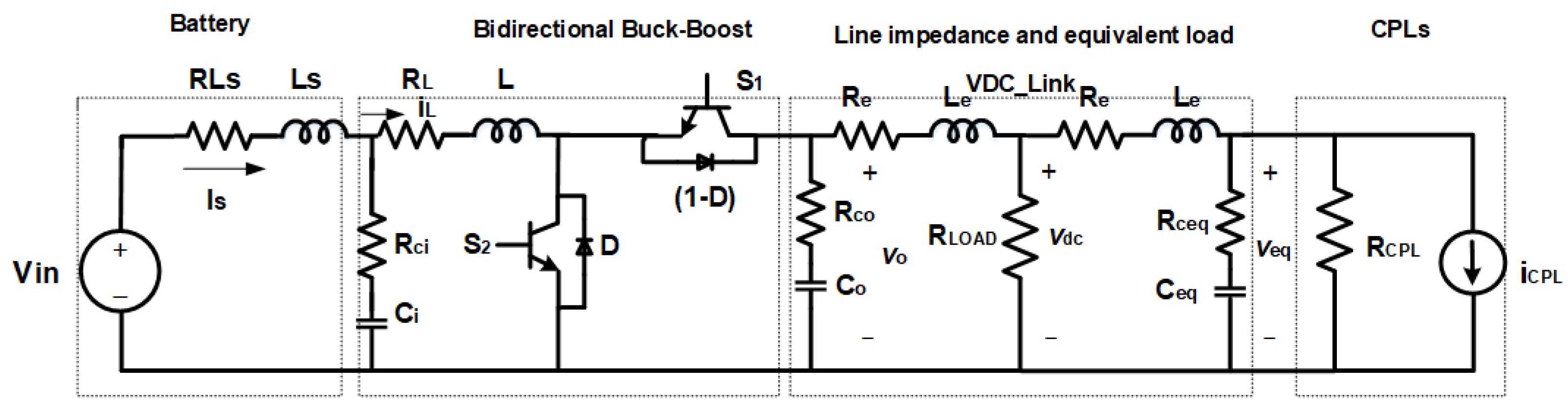
- , the energy storage element (battery).
- , the battery current.
- , the converter’s main switches.
- , the high-frequency diode, which serves to control current circulation.
- , the converter’s main inductor.
- , the converter’s output filter capacitor.
- , the constant power load impedance.
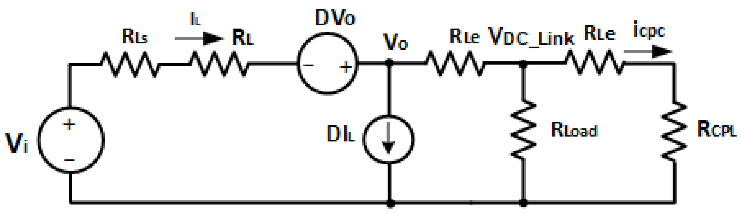
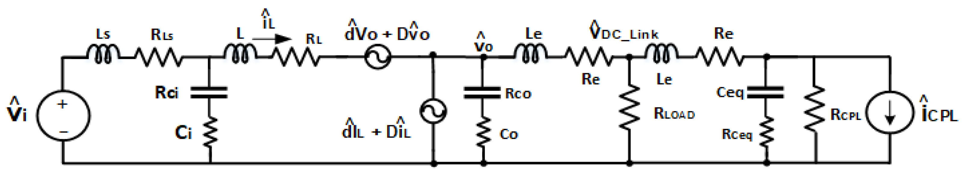
3. DC Microgrid Modeling
3.1. Current Loop Transfer Function
3.2. Voltage Loop Transfer Function
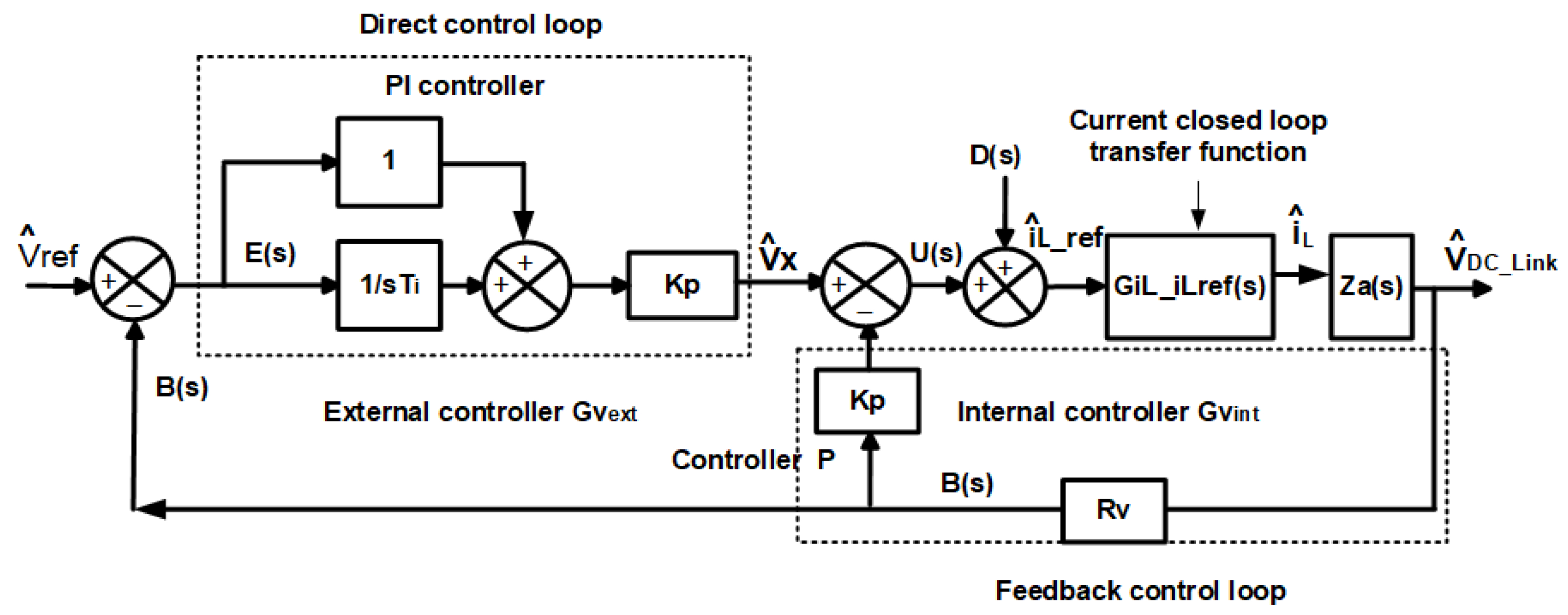
4. Controller Design
- where
- is the transfer function of the current controller.
- is the transfer function of the voltage controller.
- ) is the transfer function of the current in the inductor in relation to the duty cycle.
- is the transfer function of the to the inductor current, expressed by (19).
- is the digital delay, expressed by (20).
- is the current sensor gain.
- is the voltage sensor gain.
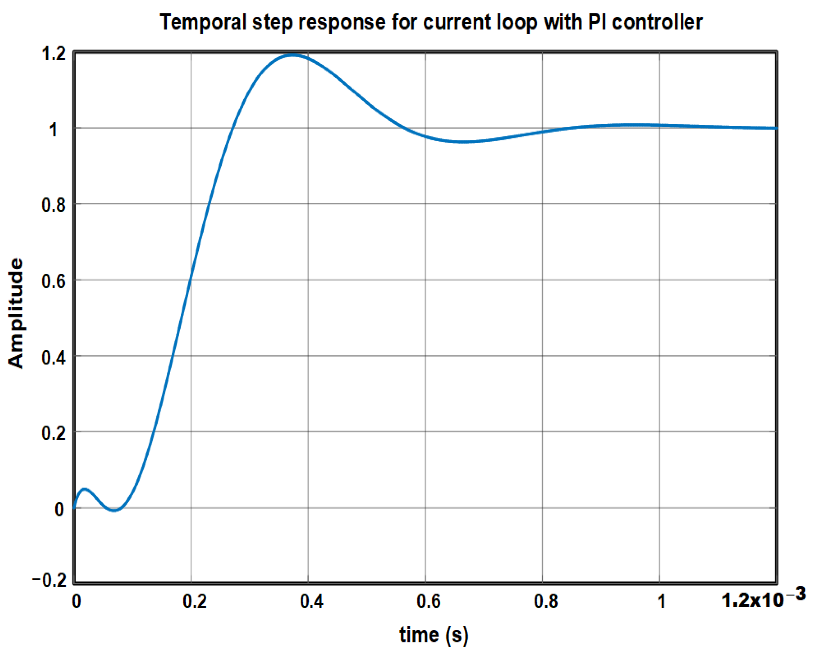
4.1. Current Control Design
PI Current Controller Design
4.2. Voltage Loop Controller
4.2.1. PI Voltage Controller Design
4.2.2. Modified PID Controller Design
- The proportional controller () is initially designed in the internal voltage loop for a frequency lower than the frequency current loop controller (1 kHz). It is important to mention that a gain sweep () was performed in an interval of 0.3 to 1.5 for this control, aiming to validate its performance in the frequency domain and the time domain.
- Once the internal loop voltage controller () is designed, the external loop controller is designed with a control configuration for a crossover frequency lower than the internal loop controller crossover frequency, maintaining the Nyquist stability criteria mentioned in Section 4.1.
5. Tests and Results Obtained by Simulations
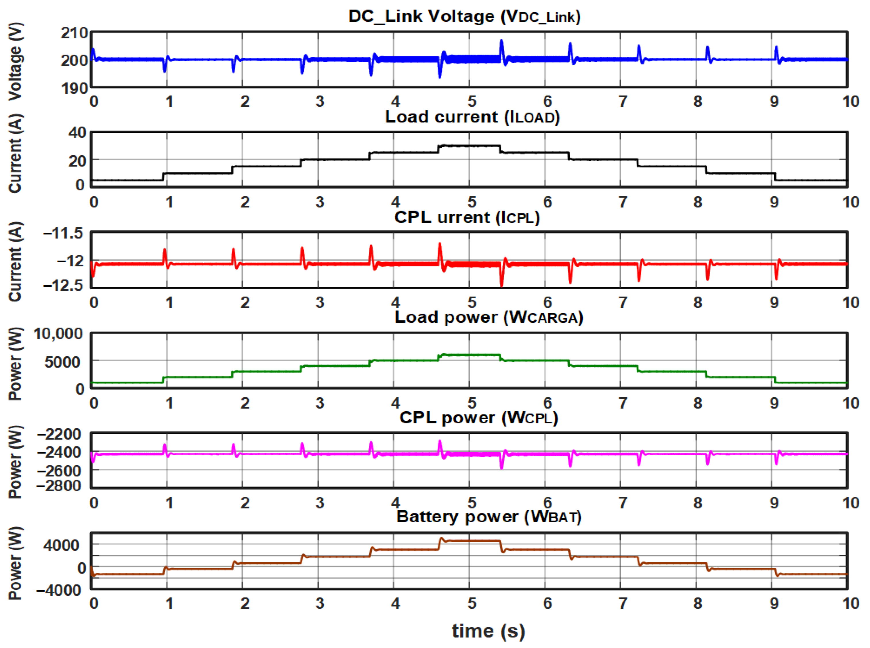
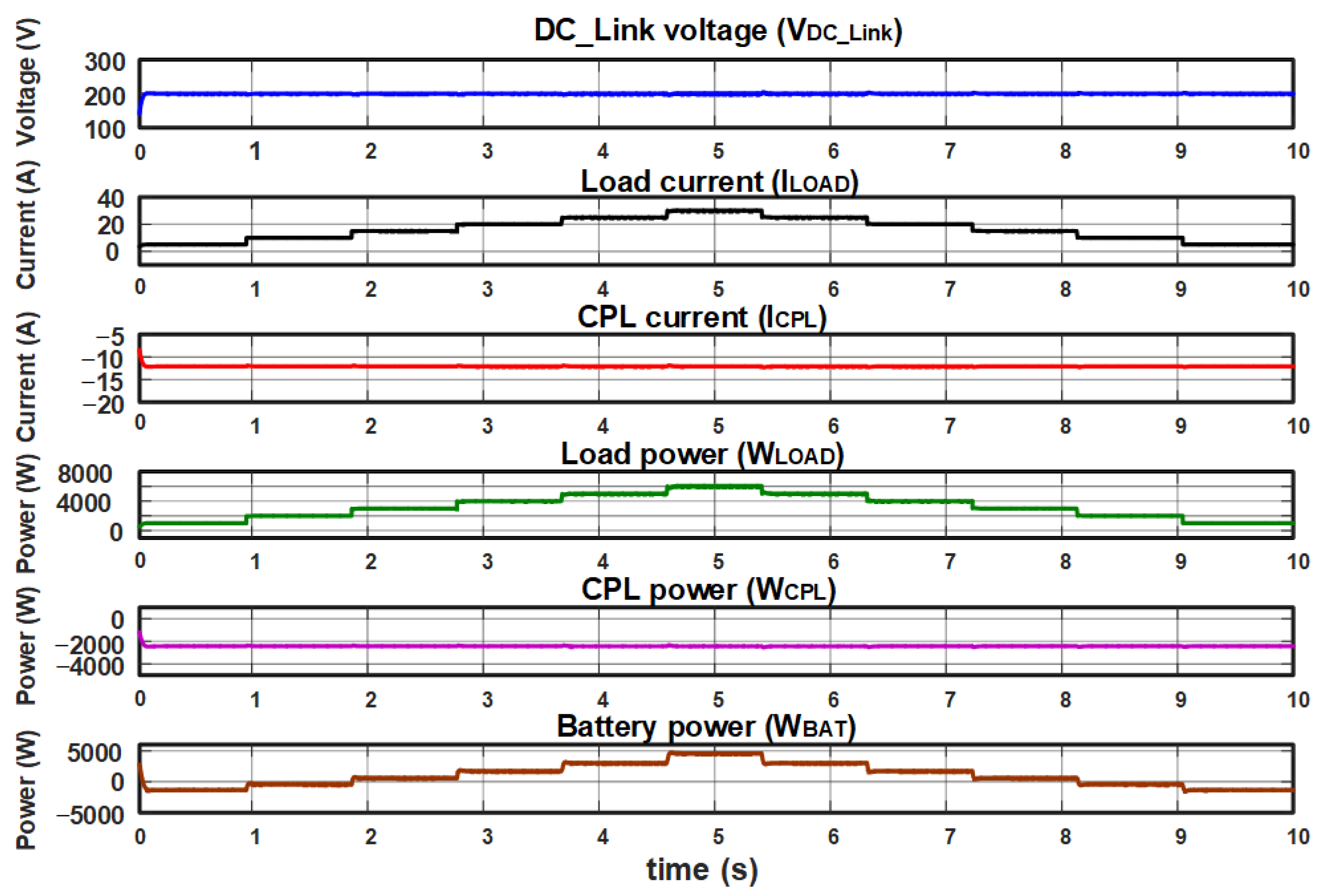
- Tests with variable local load and constant CPL power, using a PI controller in the current loop and a PI controller in the voltage loop.
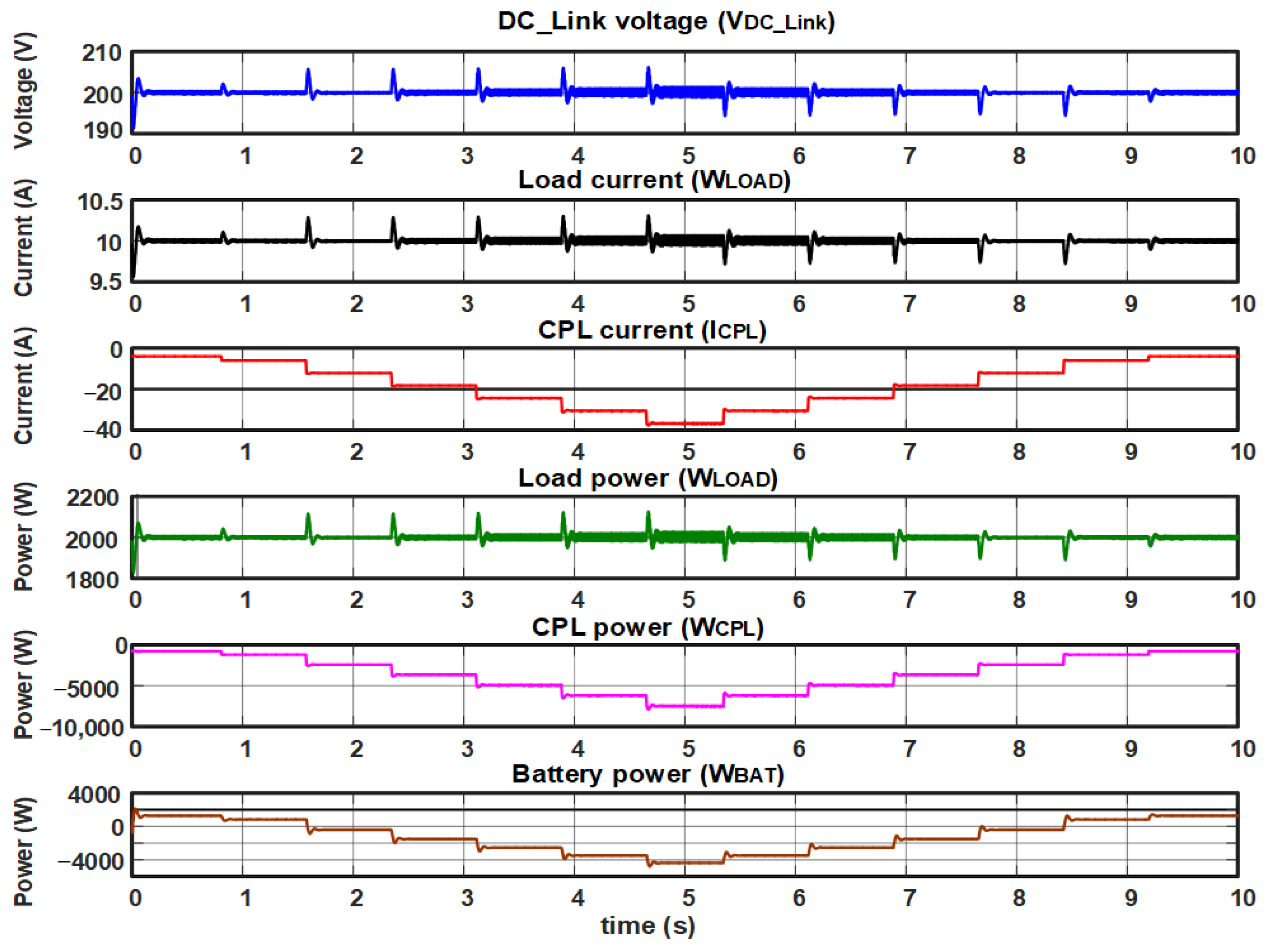
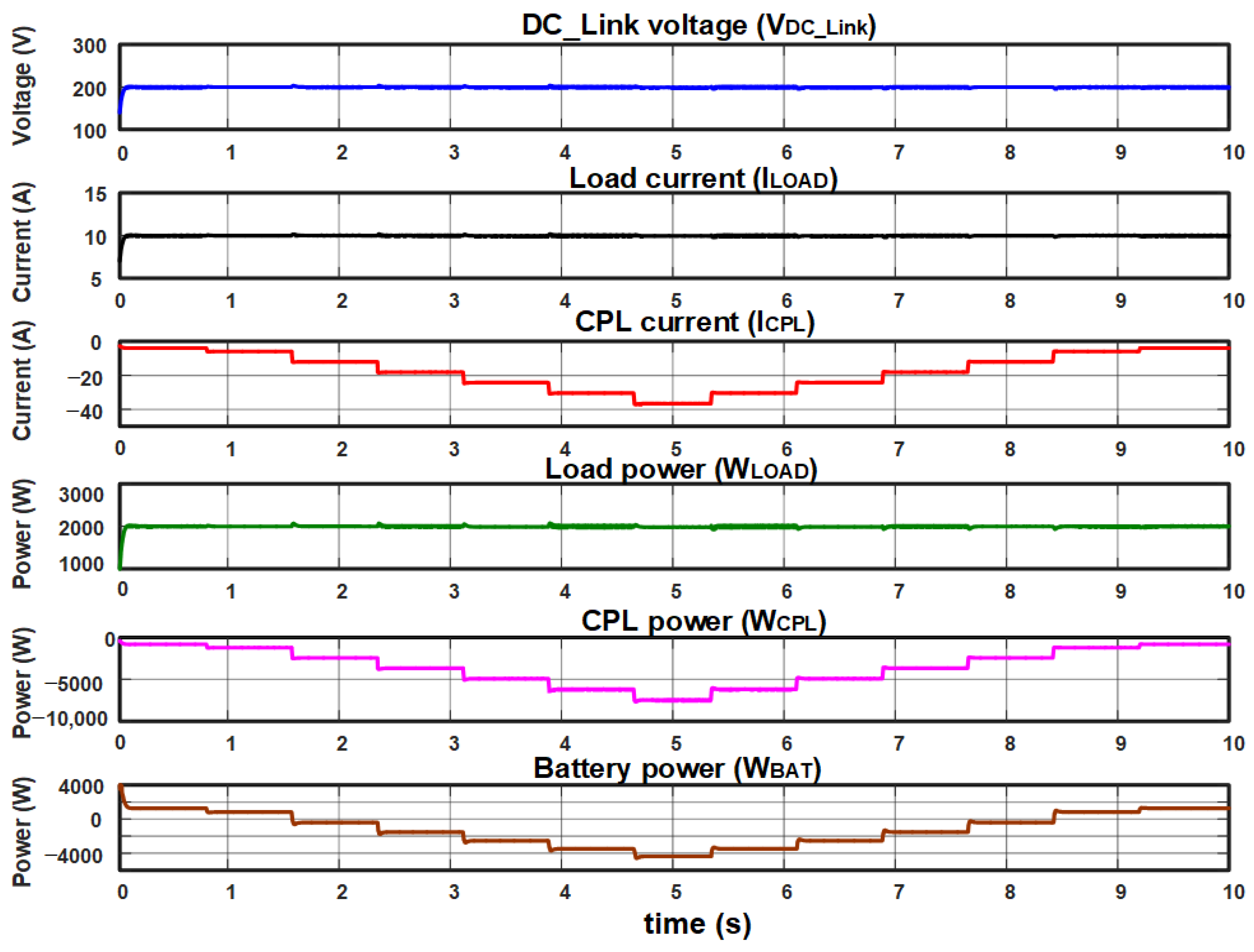
- Tests with constant local load and variable CPL power, using a PI controller in the current loop and a PI controller in the voltage loop.
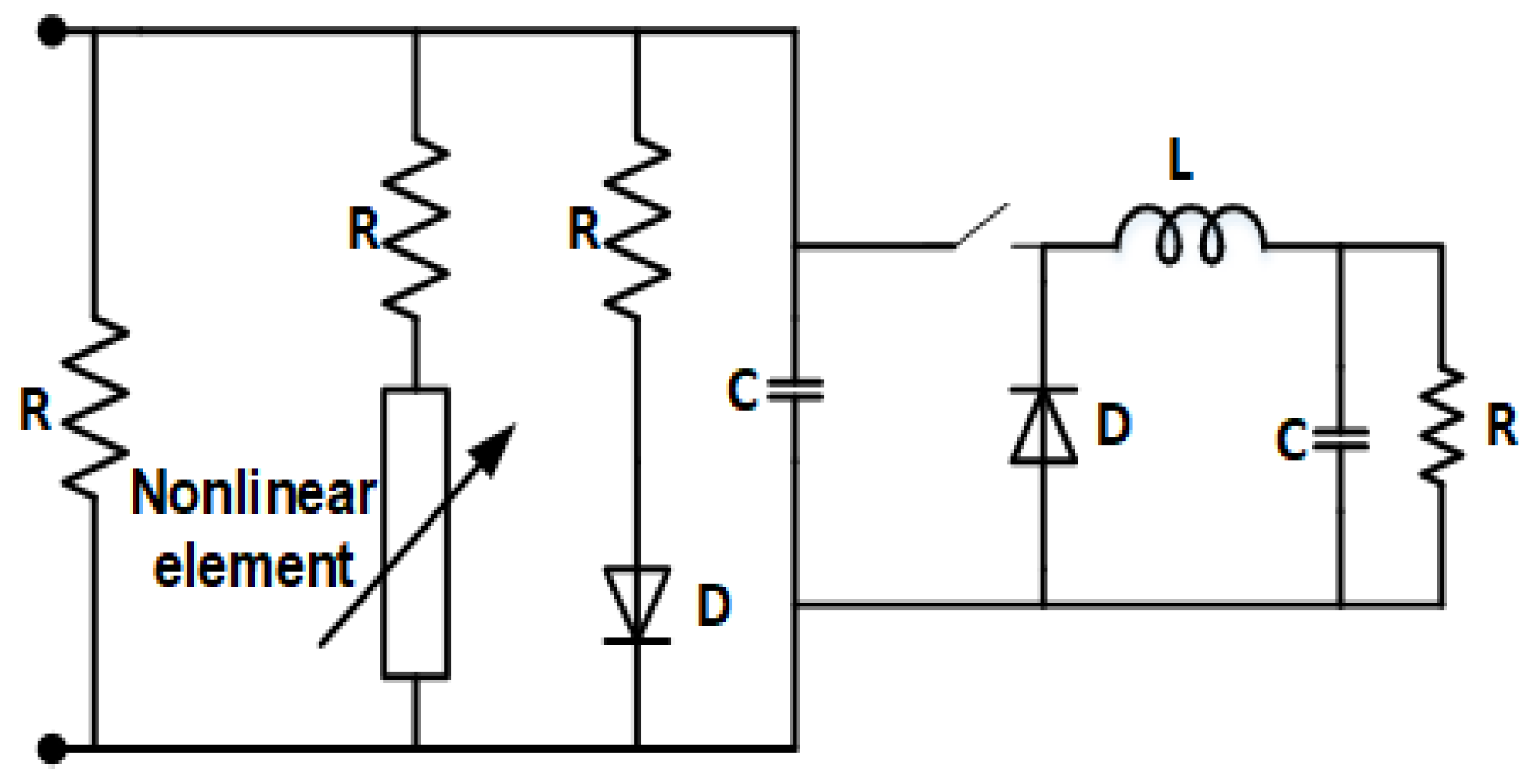
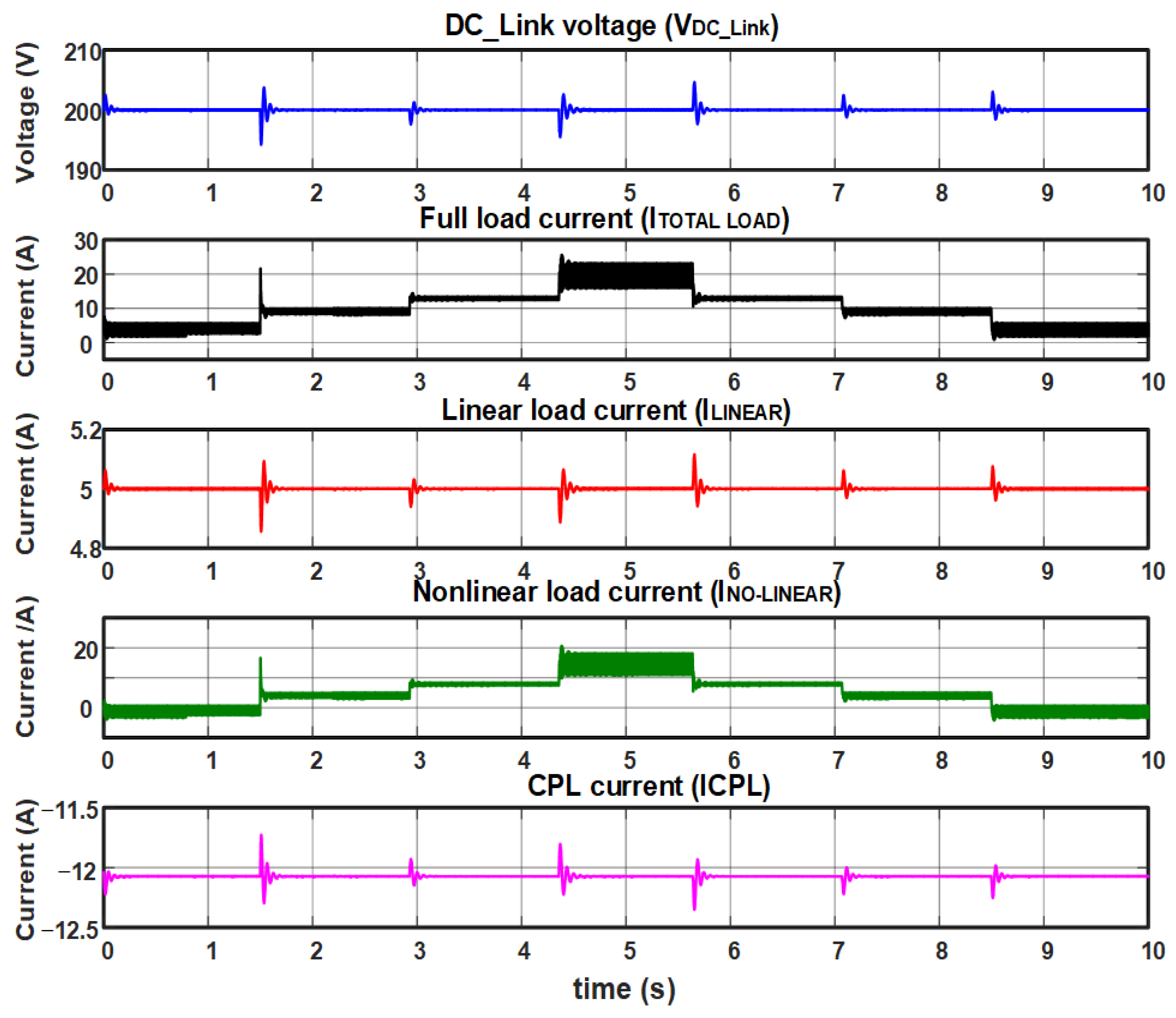
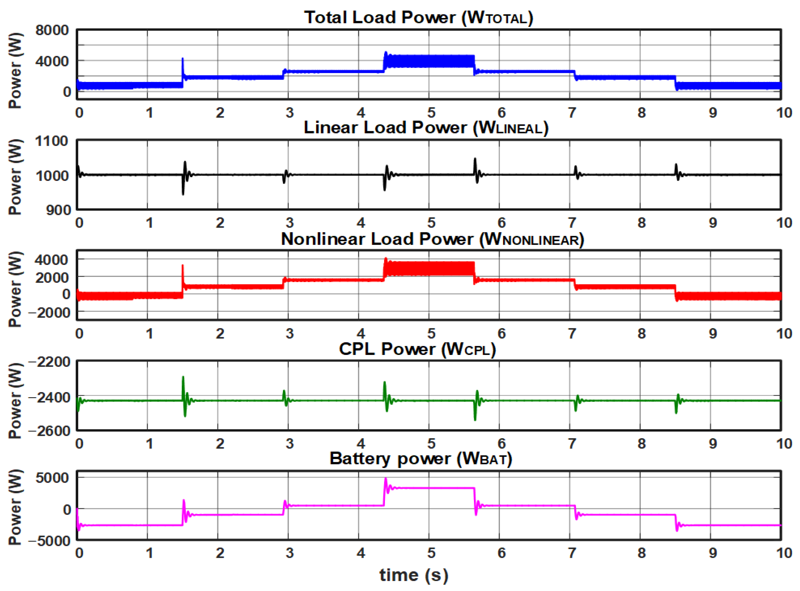
- Tests with linear local load, constant CPL power, and variable non-linear load, using a PI control in the current loop and a PI controller in the voltage loop.
5.1. Tests with PI Controller in the Current Loop and PI in the Voltage Loop
5.1.1. Test 1
5.1.2. Test 2
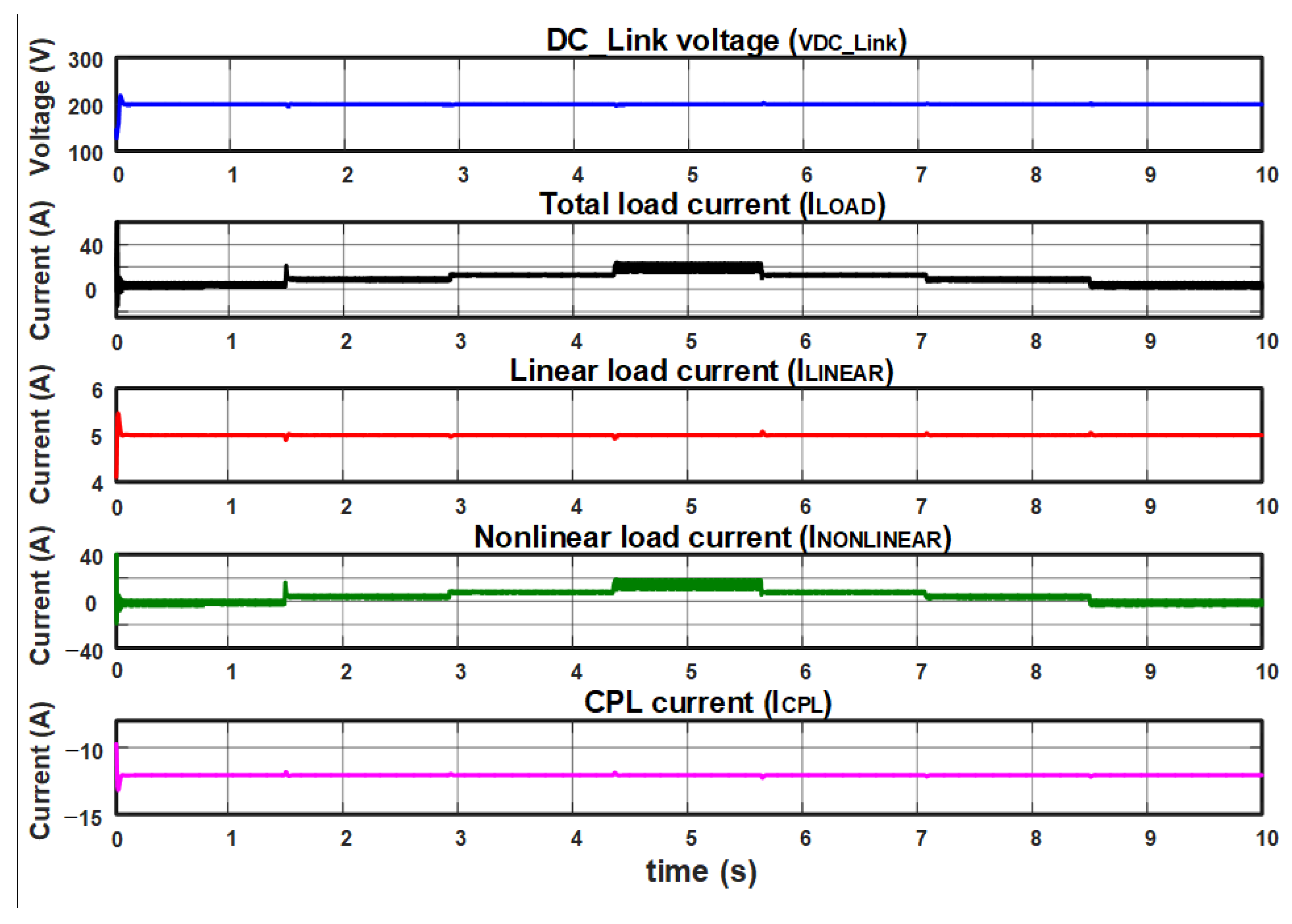
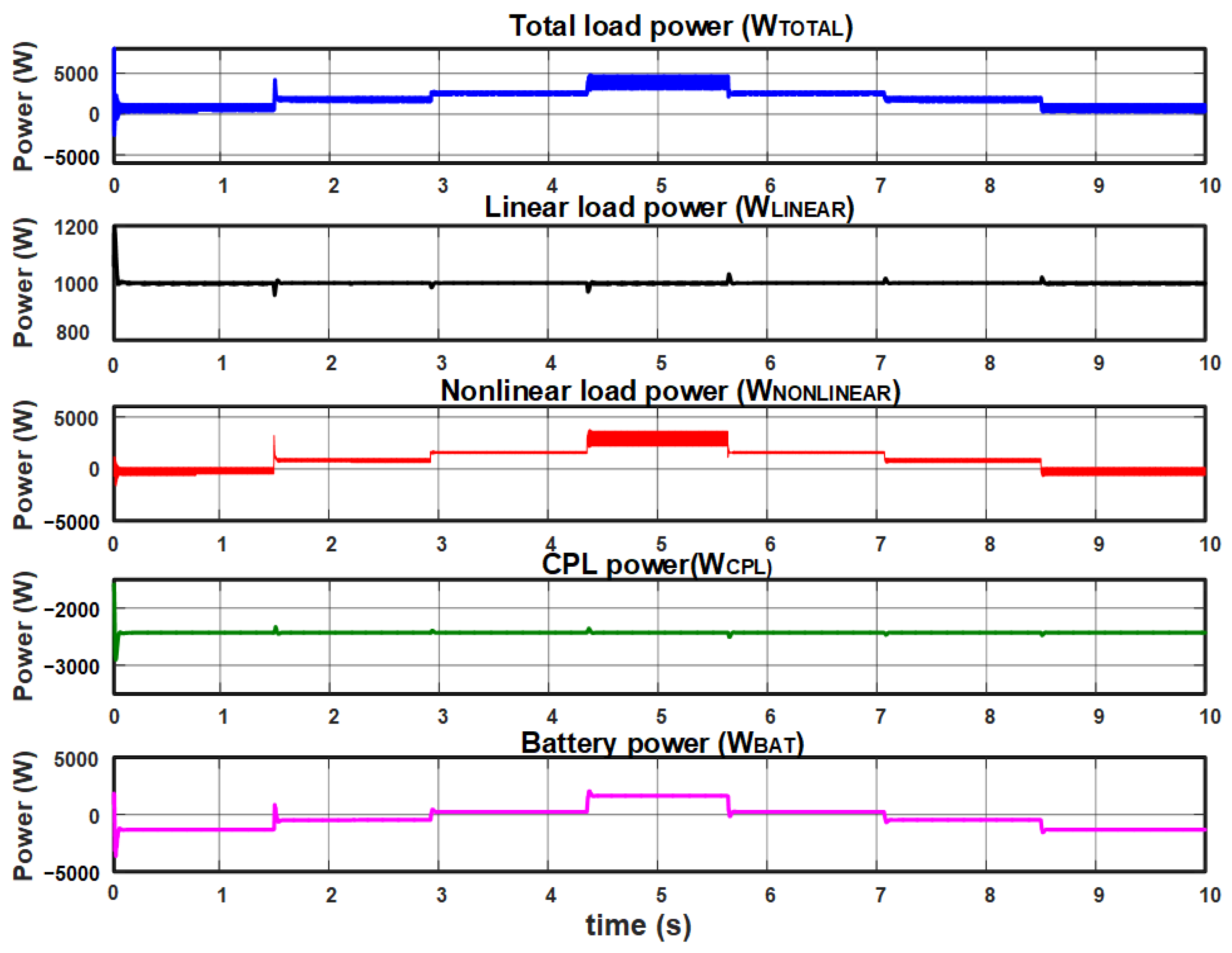
5.1.3. Test 3
5.2. Tests with PI Controller in the Current Loop and Modified PI-P in the Voltage Loop
5.2.1. Test 1
5.2.2. Test 2
5.2.3. Test 3
6. Analysis of Results
7. Conclusions
Author Contributions
Funding
Data Availability Statement
Acknowledgments
Conflicts of Interest
References
- Cao, X.; Wang, J.; Zeng, B. Distributed Generation Planning Guidance Through Feasibility and Profit Analysis. IEEE Trans. Smart Grid 2018, 9, 5473–5475. [Google Scholar] [CrossRef]
- Saeed, M.H.; Fangzong, W.; Kalwar, B.A.; Iqbal, S. A Review on Microgrids’ Challenges & Perspectives. IEEE Access 2021, 9, 166502–166517. [Google Scholar]
- Che, L.; Shahidehpour, M.; Alabdulwahab, A.; Al-Turki, Y. Hierarchical Coordination of a Community Microgrid with AC and DC Microgrids. IEEE Trans. Smart Grid 2015, 6, 3042–3051. [Google Scholar] [CrossRef]
- Al-Ismail, F.S. DC Microgrid Planning, Operation, and Control: A Comprehensive Review. IEEE Access 2021, 9, 36154–36172. [Google Scholar] [CrossRef]
- Kondrath, N. Bidirectional DC-DC converter topologies and control strategies for interfacing energy storage systems in microgrids: An overview. In Proceedings of the 2017 IEEE International Conference on Smart Energy Grid Engineering (SEGE), Oshawa, ON, Canada, 14–17 August 2017. [Google Scholar]
- Nagamalli, K.R.; Tadepalli, P.S.; Pullaguram, D.R. Effect of CPL on the Stability of DC Microgrid. In Proceedings of the 2022 IEEE 2nd International Conference on Sustainable Energy and Future Electric Transportation (SeFeT), Hyderabad, India, 4–6 August 2022. [Google Scholar]
- Hamidi, S.A.; Nasiri, A. Stability analysis of a DC-DC converter for battery energy storage system feeding CPL. In Proceedings of the 2015 IEEE International Telecommunications Energy Conference (INTELEC), Osaka, Japan, 18–22 October 2015. [Google Scholar]
- Espina, E.; Llanos, J.; Burgos-Mellado, C.; Cárdenas-Dobson, R.; Martínez-Gómez, M.; Sáez, D. Distributed Control Strategies for Microgrids: An Overview. IEEE Access 2020, 8, 193412–193448. [Google Scholar] [CrossRef]
- Andalibi, M.; Hajihosseini, M.; Gheisarnejad, M.; Khooban, M.-H.; Boudjadar, J. A Novel Method for Stabilizing Buck-Boost Converters with CPL using Model Prediction Control. In Proceedings of the 2021 22nd IEEE International Conference on Industrial Technology (ICIT), Valencia, Spain, 10–12 March 2021. [Google Scholar]
- Lucas-Marcillo, K.E.; Plaza, D.A.; Barra, W.; Paiva, R.L.; Melo, E.; Vaca-Benavides, D.A.; Ríos, S.J.; Herrera, E.V. Novel Robust Methodology for Controller Design Aiming to Ensure DC Microgrid Stability Under CPL Power Variation. IEEE Access 2019, 7, 64206–64222. [Google Scholar] [CrossRef]
- Xu, Q.; Vafamand, N.; Chen, L.; Dragičević, T.; Xie, L.; Blaabjerg, F. Review on Advanced Control Technologies for Bidirectional DC/DC Converters in DC Microgrids. IEEE J. Emerg. Sel. Top. Power Electron. 2021, 9, 1205–1221. [Google Scholar] [CrossRef]
- Li, Y.; Vannorsdel, K.R.; Zirger, A.J.; Norris, M.; Maksimovic, D. Current Mode Control for Boost Converters with Constant Power Loads. IEEE Trans. Circuits Syst. 2012, 59, 198–206. [Google Scholar] [CrossRef]
- Li, X.; Jiang, W.; Wang, J.; Wang, P.; Wu, X. An Autonomous Control Scheme of Global Smooth Transitions for Bidirectional DC-DC Converter in DC Microgrid. IEEE Trans. Energy Convers. 2021, 36, 950–960. [Google Scholar] [CrossRef]
- Kwon, M.; Choi, S. Control Scheme for Autonomous and Smooth Mode Switching of Bidirectional DC–DC Converters in a DC Microgrid. IEEE Trans. Power Electron. 2018, 33, 7094–7104. [Google Scholar] [CrossRef]
- Sidorov, V.; Chub, A.; Vinnikov, D.; Lindvest, A. Novel Universal Power Electronic Interface for Integration of PV Modules and Battery Energy Storages in Residential DC Microgrids. IEEE Access 2023, 11, 30845–30858. [Google Scholar] [CrossRef]
- Pires, V.F.; Cordeiro, A.; Roncero-Clemente, C.; Rivera, S.; Dragičević, T. DC–DC Converters for Bipolar Microgrid Voltage Balancing: A Comprehensive Review of Architectures and Topologies. IEEE J. Emerg. Sel. Top. Power Electron. 2023, 11, 981–998. [Google Scholar] [CrossRef]
- Chen, D.; Xu, L.; Yao, L. DC Voltage Variation Based Autonomous Control of DC Microgrids. IEEE Trans. Power Deliv. 2013, 28, 637–648. [Google Scholar] [CrossRef]
- Pannala, S.; Patari, N.; Srivastava, A.K.; Padhy, N.P. Effective Control and Management Scheme for Isolated and Grid Connected DC Microgrid. IEEE Trans. Ind. Appl. 2020, 56, 6767–6780. [Google Scholar] [CrossRef]
- Mohammadi, F.; Mohammadi-Ivatloo, B.; Gharehpetian, G.B.; Ali, M.H.; Wei, W.; Erdinç, O.; Shirkhani, M. Robust Control Strategies for Microgrids: A Review. IEEE Syst. J. 2022, 16, 2401–2412. [Google Scholar] [CrossRef]
- IEEE Std 2030.10-2021; IEEE Standard for DC Microgrids for Rural and Remote Electricity Access Applications. IEEE: New York, NY, USA, 2020; pp. 1–47.
- Al-Obaidi, N.A.; Abbas, R.A.; Khazaal, H.F. A Review of Non-Isolated Bidirectional DC-DC Converters for Hybrid Energy Storage System. In Proceedings of the 2022 5th International Conference on Engineering Technology and Its Applications (IICETA), Al-Najaf, Iraq, 31 May–1 June 2022. [Google Scholar]
- Farsizadeh, H.; Gheisarnejad, M.; Mosayebi, M.; Rafiei, M.; Khooban, H.M. An Intelligent and Fast Controller for DC/DC Converter Feeding CPL in a DC Microgrid. IEEE Trans. Circuits Syst. 2020, 67, 1104–1108. [Google Scholar] [CrossRef]
- Liu, X.; Zhao, T.; Deng, H.; Wang, P.; Liu, J.; Blaabjerg, F. Microgrid Energy Management with Energy Storage Systems: A Review. CSEE J. Power Energy Syst. 2023, 9, 483–504. [Google Scholar]
- Cho, K.M.; Oh, W.S.; Kim, Y.T.; Kim, H.J. A New Switching Strategy for Pulse Width Modulation (PWM) Power Converters. IEEE Trans. Ind. Electron. 2007, 54, 330–337. [Google Scholar] [CrossRef]
- Liao, Y.; Wang, X. Small-Signal Modeling of AC Power Electronic Systems: Critical Review and Unified Modeling. IEEE Open J. Power Electron. 2021, 2, 424–439. [Google Scholar] [CrossRef]
- Mohan, N.; Undeland, T.; Robbins, W. Power Electronics: Converters, Applications, and Design, 3rd ed.; John Wiley & Sons: Hoboken, NJ, USA, 2002. [Google Scholar]
- He, S.; Hung, J.Y.; Nelms, R.M. Small-Signal Modeling of I2 Average Current Mode Control. IEEE Trans. Power Electron. 2016, 31, 3849–3858. [Google Scholar] [CrossRef]
- Ogata, K. Modern Control Engineering, 4th ed.; Prentice Hall: Upper Saddle River, NJ, USA, 2002. [Google Scholar]
- Benavent, J.M.; Figueres, E.; Garcera, G.; Pascual, M. Robust model-following regulator for average current-mode control of boost DC-DC converters. In Proceedings of the ISIE 2005 IEEE International Symposium on Industrial Electronics, Dubrovnik, Croatia, 20–23 June 2005. [Google Scholar]
- PSIM 11.1 User’s Guide; Powersim: Rockville, MD, USA, 2018.


| Description | Parameter | Value | Units |
|---|---|---|---|
| Converter output voltage | 200 | V | |
| DC_Link Voltage | 200 | V | |
| Input voltage | 100 | V | |
| Switching frequency | 10 | kHz | |
| Duty cycle | 0.8 | ---- | |
| Battery inductance | 2 | ||
| Battery parasitic resistance | 0.04 | ||
| Input capacitance | 1000 | ||
| Input capacitor parasitic resistance | 0.074 | ||
| Converter input inductance | 2.2 | ||
| Converter inductor parasitic resistance | 0.04 | ||
| Converter output capacitance | 2700 | ||
| Converter output capacitor parasitic resistance | 0.1 | ||
| Converter output inductance | 0.1 | ||
| Converter output inductor parasitic resistance | 0.1 | ||
| Converter output equivalent capacitance | 5600 | ||
| Converter output equivalent capacitance parasitic resistance | 0.1 | ||
| Load impedance | 60 | ||
| CPL power | 1.2 | ||
| CPL impedance | −33.33333 | ||
| CPL current | iCPL | 6.0 | A |
| Converter output current | 3.333 | A | |
| Inductor current | 6.666 | A | |
| Converter input impedance | Zin | 0.04 | |
| Converter output impedance | Zvo | 0.1 |
| Controller | VDC_LINK (V) | ILOAD (A) | ICPL (A) | WLOAD (Watts) | WCPL (Watts) | WBAT (Watts) |
|---|---|---|---|---|---|---|
| Modified PID | 200 | 5 to 30 | −12 | 1000 to 6000 | −2400 | −1200 to 4200 |
| PI | 200 | 5 to 35 | −11 | 1000 to 5943 | −2426 | −1328 to 4581 |
| Controller | VDC_LINK (V) | ILOAD (A) | ICPL (A) | WLOAD (Watts) | WCPL (Watts) | WBAT (Watts) |
|---|---|---|---|---|---|---|
| Modified PID | 200 | 10 | −4 to −40 | 2000 | −800 to −7500 | 1200 to −4200 |
| PI | 200 | 10 | −4 to −40 | 2000 | −800 to −7495 | 1280 to −4370 |
| Controller | VDC_LINK (V) | ITOTAL_LOAD (A) | ILINEAR (A) | INONLIEAR (A) | ICPL (A) |
|---|---|---|---|---|---|
| Modified PID | 200 | 8.0 to 22 | 5 | 3.0 to 20 | −12 |
| PI | 200 | 9.6 to 24.2 | 5 | 2.53 to19.87 | −12 |
| Controller | WTOTAL (Watts) | WLINEAR (Watts) | WNONLINEAR (Watts) | WCPL (Watts) | WBAT (Watts) |
|---|---|---|---|---|---|
| Modified PID | 1600 to 4600 | 1000 | 500 to 3800 | −2400 | −1300 to 1600 |
| PI | 1696 to 4845 | 1000 | 696 to 3846 | −2430 | −1338 to 1800 |
| Reference | Contributions |
|---|---|
| [9] | A model predictive control (MPC) approach is presented to address the destabilization problem and mitigate the destructive effect of CPLs. This leads to a robust control approach and widens the system stability margin. |
| [10] | A novel robust controller based on linear programming and Chebyshev’s theorem is described. The proposed controller aims to regulate the DC bus voltage, ensuring the MG stability due to the power-variation effects on the CPLs. |
| [11] | Advanced control technologies for bidirectional DC/DC converters in DC microgrids are described, and the stability problem caused by the CPL is analyzed, which motivates the use of this control technique. |
| [12] | This study describes how current mode control provides a suitable solution for regulating boost converters with constant power loads. Also, the corresponding small signal transfer functions are calculated for the different microgrid controller designs. |
| [13] | An autonomous control scheme is proposed for a bidirectional direct current converter (BDC) in a DC microgrid. The proposed scheme is based on V2-P droop control and unifies microgrid bus voltage and power regulations in a control structure. Therefore, a smooth transition between different modes of operation is presented. |
| [14] | This describes a bidirectional DC-DC converter control scheme for an energy storage system (ESS) that solves problems associated with the microgrid operation mode changes. |
| [15] | The novel concept of a highly versatile power electronics smart interface for fast implementation of residential DC microgrids is presented. The power flow control system is highly efficient and bidirectional over a wide operating voltage range. |
| [16] | A comprehensive multiple architectures and topologies review of power electronic converters is presented and describes the detailed classification and analysis of the advantages and disadvantages of these topologies. |
| [17] | DC microgrid control with variable energy generation and storage is described, and a three-level autonomous control strategy for DC microgrids is proposed. |
| [18] | The control design and management strategy for a backup diesel generator (DG), a renewable energy source (RES), and an energy storage system that allows you to maintain the microgrid bus voltages within the established limits is presented. |
| [19] | The robust control methods review for hybrid AC and DC microgrids with different topologies and different types of interconnections to conventional power systems is presented. |
| [Present work] | This work contributes by considering parasitic elements in the microgrid model and designing an effective controller for the voltage loop (modified-PID) to supply a constant and regulated voltage to the linear and non-linear local load. Additionally, it manages the energy drawn from CPL and controls the charging and discharging of the main battery. |
Disclaimer/Publisher’s Note: The statements, opinions and data contained in all publications are solely those of the individual author(s) and contributor(s) and not of MDPI and/or the editor(s). MDPI and/or the editor(s) disclaim responsibility for any injury to people or property resulting from any ideas, methods, instructions or products referred to in the content. |
© 2024 by the authors. Licensee MDPI, Basel, Switzerland. This article is an open access article distributed under the terms and conditions of the Creative Commons Attribution (CC BY) license (https://creativecommons.org/licenses/by/4.0/).
Share and Cite
Sánchez, H.A.; Ortega, R.; Carranza, O.; Rodríguez, J.J.; García, V.H.; Ortega, L.M.; Memije, D. Controller Design for Autonomous Direct Current Microgrid Operation. Electronics 2024, 13, 2943. https://doi.org/10.3390/electronics13152943
Sánchez HA, Ortega R, Carranza O, Rodríguez JJ, García VH, Ortega LM, Memije D. Controller Design for Autonomous Direct Current Microgrid Operation. Electronics. 2024; 13(15):2943. https://doi.org/10.3390/electronics13152943
Chicago/Turabian StyleSánchez, Hernán A., Rubén Ortega, Oscar Carranza, Jaime J. Rodríguez, Víctor H. García, Luis M. Ortega, and Daniel Memije. 2024. "Controller Design for Autonomous Direct Current Microgrid Operation" Electronics 13, no. 15: 2943. https://doi.org/10.3390/electronics13152943
APA StyleSánchez, H. A., Ortega, R., Carranza, O., Rodríguez, J. J., García, V. H., Ortega, L. M., & Memije, D. (2024). Controller Design for Autonomous Direct Current Microgrid Operation. Electronics, 13(15), 2943. https://doi.org/10.3390/electronics13152943