Abstract
Reconfigurable intelligent surface (RIS) is composed of large quantities of inexpensive passive elements, which is able to adjust phase and amplitude shifts to reduce the system power consumption. However, the complex coupling in the RIS-aided system makes the power minimization (PowerMin) problem more difficult when compared to conventional systems. In this paper, a three-dimensional (3D) time-varying channel model is proposed for RIS-assisted networks and a downlink expression between mobile vehicles and users is derived. Additionally, a successive convex approximation (SCA) method is provided and the transmitter beamformer and RIS phase shifts are updated simultaneously at each iteration to achieve a satisfactory numerical solution. Ultimately, the simulation model in MOSEK version 10.1.28 is utilized to verify the effectiveness of analytical results.
1. Introduction
With the increasing demand for better performance and wider bandwidth in sixth-generation (6G) systems [1,2], reconfigurable intelligent surface (RIS) is recognized as a crucial method for communication systems [3,4,5]. RIS is made up of a planar metasurface with numerous low-cost passive reflective elements connected to an intelligent control unit. By making appropriate adjustments to the electromagnetic response of incoming radio waves, the phase and amplitude of signals are intelligently designed to achieve efficient, secure, and reliable wireless networks [6].
1.1. Related Work
Recently, various studies have been conducted about RIS-assisted communication systems, with the aim of enhancing the performance and extending coverage area. The authors of [7] showed that the coverage performance of the system can be greatly improved by optimizing beamforming in the RIS-assisted network, which provided an important theoretical basis for subsequent research. The authors of [8] further explored the multiple-input multiple-output (MIMO) channel covariance matrix as well as optimized the autonomous phase shifts and/or magnitudes of the RIS. The authors of [9,10] investigated how to improve the attainable rates of unmanned aerial vehicle (UAV) scenarios in multiple-input single-output (MISO) networks. This work studied the application of RIS from the new perspective of dynamic environments. The authors of [11] proposed a capacity optimization algorithm for RIS-assisted MIMO communication systems. In [12], a novel two-stage channel estimation scheme was proposed, to improve the channel estimation performance in RIS-assisted communication systems. Furthermore, in RIS-aided large-scale Internet of Things (IoT) networks, the mean square error (MSE) performance of the channel estimator and the error probability performance of the active device detection can be significantly enhanced [13,14].
Additionally, the research in [15] found that when the beamformings at the input point and RIS were combined, the security of the physical layer link was greatly improved. It is noted that RIS is capable of operating in full-duplex mode with no extra power required for signal amplification/regeneration as well as no complex self-interference cancelling processing, which is significantly different from traditional active relays. To justify this point, potential similarities and dissimilarities of the RIS and active relays, as well as the cost-effectiveness and energy efficiency were analyzed [16]. Additionally, the problem of power minimization (PowerMin) was further complicated by the coupling effect of RIS compared to relay-assisted systems. The works of [17,18,19] investigated the PowerMin problem in the context of RIS-assisted multi-user single-input single-output (MU-SISO) downlink, and explored the multi-user single-input multiple-output (MU-SIMO) uplink system. In [20], the second-order cone programming (SOCP) method was used to optimize the PowerMin problem in the multi-user MISO (MU-MISO) downlink system.
In order to delineate the characteristics of RIS-assisted communication systems more precisely, a general three-dimensional (3D) wideband non-stationary channel model for RIS-assisted MIMO communication systems was proposed in [21]. Subsequently, the channel model can be used to describe a variety of RIS-assisted communication scenarios in [22]. In addition, the RIS technique has been demonstrated its unique strengths in areas such as mmWave mobile systems, vehicle-to-vehicle (V2V) propagation environments, and UAV communications. The authors of [23] investigated the alternating disappearance and reappearance of LoS paths, while the research in [24] focused on V2V propagation environments. In [25,26], a 3D-based MIMO channel model was proposed for the RIS-assisted UAV communication. Finally, the authors of [27,28] proposed a 3D communication channel model with dual RIS co-assisted MIMO, which confirmed the advantages of dual RIS in enhancing communication performance and provided a new idea for the design of future communication systems.
1.2. Motivations
However, the PowerMin problem in time-varying communication systems has rarely been compared and analyzed. The described methods are primarily constrained by simplified mathematical models. Although the problem of optimization can be significantly simplified by alternating optimization, high-performance solutions are not guaranteed due to the complex coupling between the optimization variables. From the perspective of the computational complexity, semidefinite relaxation (SDR) [29,30] is not suitable for large-scale time-varying systems. It motivates us to propose an algorithm with lower computational complexity. By using appropriate model parameters, the designed algorithm can be applied to the time-varying communication system, and a more effective numerical solution for the PowerMin problem is finally verified.
1.3. Contributions
A 3D time-varying channel model is proposed for RIS-assisted MU-MISO systems. The PowerMin problem is then solved using a more efficient numerical solution based on SOCP. The main contributions can be summarized as follows.
- A 3D time-varying channel model for RIS-assisted MU-MISO systems is established. The relative positions between Tx, and RIS, as well as the number of RIS units are considered. Besides, this model not only considers the traditional propagation path, but also pays special attention to the directional obstruction under the direct propagation path, which provides a more accurate basis for the subsequent study of the power control.
- A detailed algorithm is provided for characterizing the transmitted power of the RIS-assisted channel. However, this problem is not a convex problem, which makes it challenging to obtain an optimal solution. Therefore, a successive convex approximation (SCA)-based SOCP algorithm is given, and the transmitted beamforming and phase shifts are simultaneously updated during each iteration to achieve a better numerical solution.
- To assess the effectiveness of the proposed system, extensive simulation results are provided. It is indicated in our findings that the SOCP time-varying algorithm is converged by constraining violation parameters and target values. The average transmit power in high-mobility communication scenarios is significantly enhanced and the performance of communication between high-speed vehicles and users is improved.
The subsequent sections of the article are organized as follows. Section 2 describes the proposed MU-MISO time-varying channel model. Section 3 introduces and examines a time-varying beamforming optimization method based on the SOCP. Section 4 provides numerical results and discussions. Ultimately, our findings are outlined in Section 5.
Notation: The symbols , , and signify the absolute value, norm, matrix transpose, and hermitian transpose; , , and take the real part, imaginary part, complex-valued matrix of size , and diagonal matrix, respectively.
2. System Model
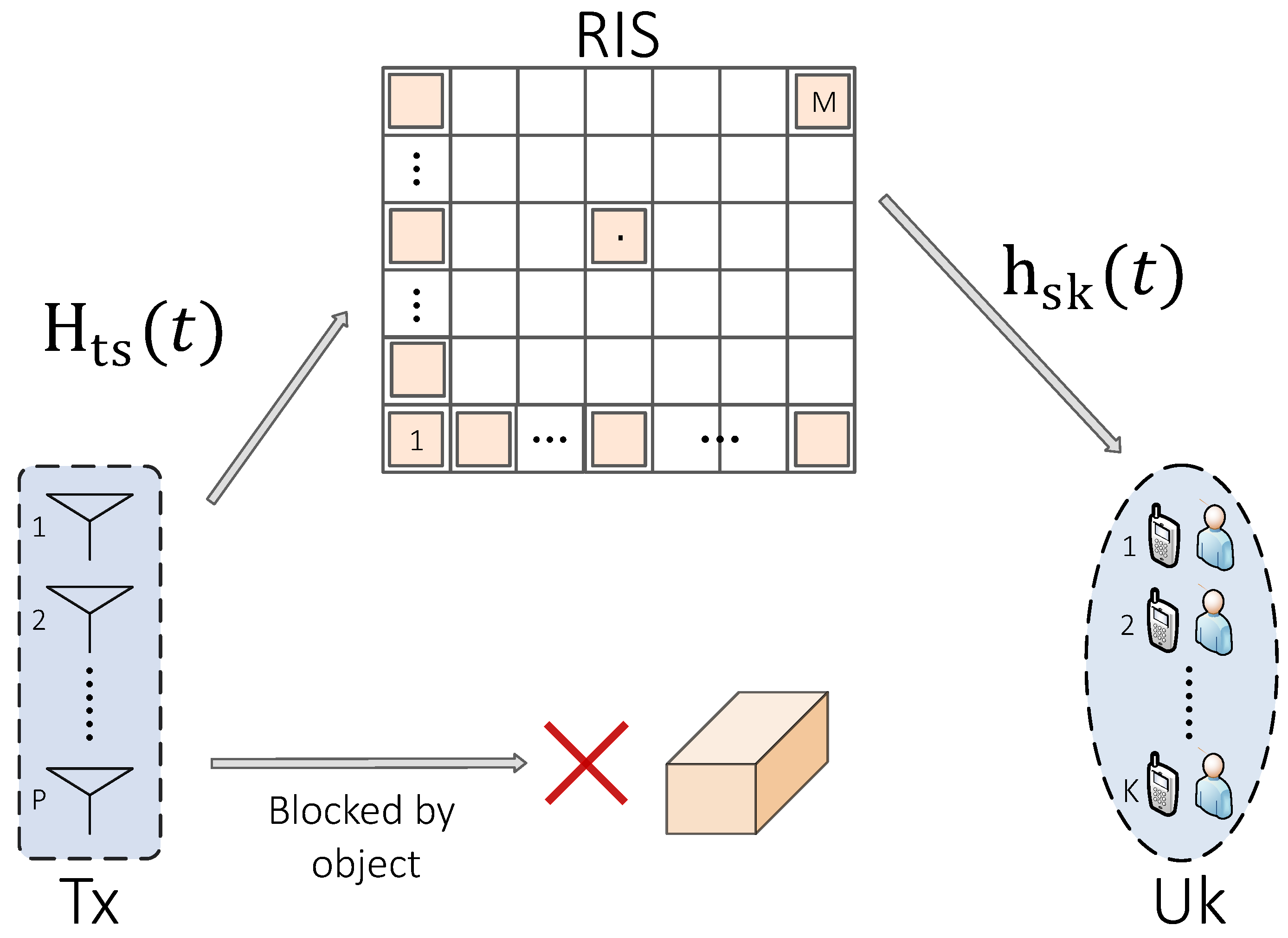
As illustrated in Figure 1, a typical MU-MISO communication scenario is considered. The direct path from the mobile transmitter (Tx) to K single-antenna users (defined as ) is obstructed by harsh propagation environments, such as buildings and trees. Consequently, RIS with nearly-passive reflecting elements is introduced to enhance the communication performance. At the same time, Tx is equipped with P antenna units, and the spacing between adjacent antenna units is represented by .
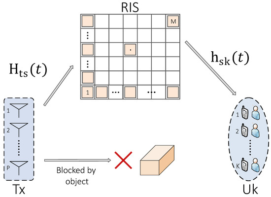
Figure 1.
Diagram of RIS-assisted MU-MISO downlink model.
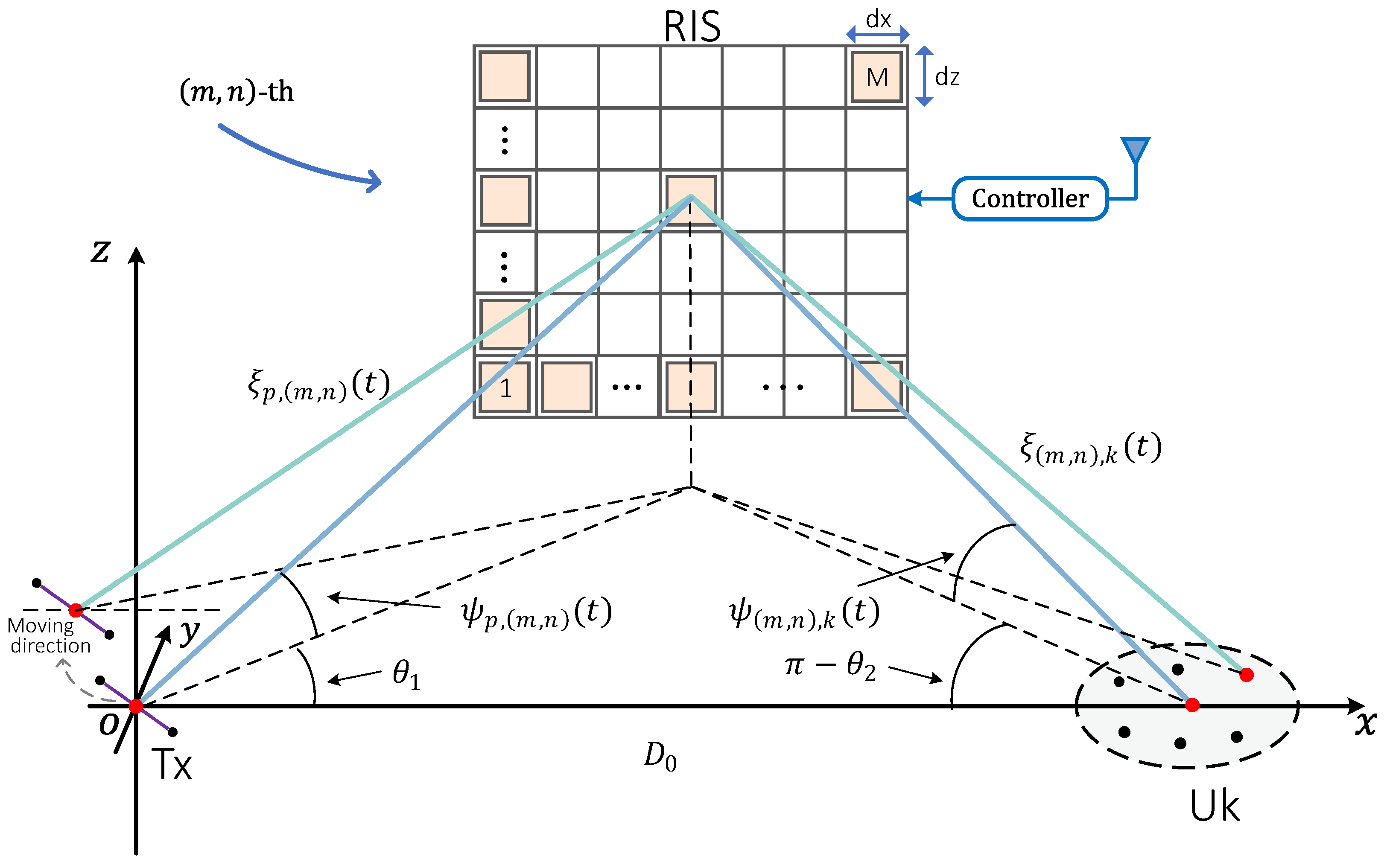
Then, a spatial coordinate system is established as shown in Figure 2. The centre of the Tx arrays is the coordinate origin. The position of is in the plane, while RIS is in the plane. In this model, the Tx and are placed on the ground, and RIS is positioned on a vertical wall, with columns and rows denoted by M and N. The centre of the RIS is positioned at the coordinates , and they are respectively given by
where stands for the distance from Tx to . is the inclination of the centre of Tx arrays to RIS with respect to the x-axis, and is the inclination of the centre of arrays to RIS with respect to the x-axis. Each grid of RIS is represented by the length and width . Assuming that m and n are even numbers, and the position of the elements in the grid can be represented as .
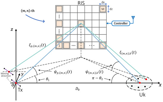
Figure 2.
Proposed 3D time-varying channel model for RIS-assisted MU-MISO communication scenarios.
In the following part, and are adopted to characterize the physical properties of the Tx-RIS and RIS- subchannels, where t is the movement time of Tx. Therefore, the channel model is expressed as
where denotes the reflection coefficient matrix, with , being the phase shift.
It should be mentioned that the expression of the time-variant channel matrix yields , and the time-varying function in the p– link, i.e., , is given by
where the p– link is divided into line-of-sight (LoS) and non-line-of-sight (NLoS) links. is LoS link, and is the NLoS link. is the carrier wavelength, and is the Rician coefficient. and are the velocity and direction of Tx movement, respectively. is the random phase angle in the Gaussian distribution with a range of [ , ]. is the path loss coefficient in the p– link, and it can be given by
where represents the transmission antenna gain of Tx, is the path loss exponent of RIS, and and are the time-varying distance and cosine angle, respectively, of the p– link. They can be derived from the values of , that is
Similarly, the expression of the time-variant channel matrix is where is the time-varying function in –k link, and can be written as
where the –k link is divided into LoS and NLoS links. is the LoS link, and is the NLos link. is the path loss coefficient in the –k link, and it is denoted as
where represents the transmission antenna gain of , and is the path loss exponent of an RIS. and are the time-varying distance and cosine angle of the –k link, respectively. They can be derived from the values of , i.e.,
where and are defined as the information symbol and the respective transmit beamforming/pre-coding vector from Tx to respectively, and the k-th user receive signal is given by
where is the k-th vector in , and the circular complex symmetric additive white Gaussian noise (AWGN) at the k-th user is characterized by . Without loss of generality, it is supposed that . Furthermore, to avoid potential problems with very small values, normalization is applied to . Thus, the signal-to-interference-plus-noise ratio (SINR) is denoted by
where presents the total interference power received from all users except user k. The fundamental issue of PowerMin is solved through the simultaneous optimization of and , and thus, the minimum required SINR is achieved for each user. Specifically, the problem of optimization is described as follows:
where the initial time is denoted by , and the time interval for updating the channel state information is . The minimum value of SINR at is denoted by , which can be considered as the minimum acceptable quality of service (QoS).
3. Problem Solution
The primary challenge that must be addressed is clearly presented in Equation (12b). In this section, the problem is solved by the SCA approach convex approximations. Consequently, we have
where Equation (13a) holds true specifically when . Equations (13b,c) are derived by expanding the right-hand side (RHS) terms. The concept of SCA is applied to handle Equation (12b), and it can be equivalently expressed as
where slack variables and are introduced to make Equation (12b) equivalent to Equation (14). Since the RHS of Equation (14a) is convex, , and are introduced to identify the concave lower bound of in Equation (14a), which can be expressed as
where and are values of and , respectively, at the n-th iteration. Therefore, can be transformed into
where (a) and (c) are due to Equation (13a), and (b) is due to Equation (13b). It is possible to deduce that is simultaneously concave. Furthermore, by employing Equation (13b) in conjunction with the absolute value property, Equation (14b) can be expressed equivalently as
In order to convexify Equation (17), Equation (13a) is applied with and ; that is,
where the RHS of Equation (18) is simultaneously optimized with regard to and . Finally, the RHS is defined as . By following a similar derivation process, Equation (17b) can be approximated as
The non-convexity of Equations (20a,b) are caused by the negative quadratic term in the RHS. By employing the same derivation principle of Equations (18) and (19), a lower bound of Equation (20) can be established as follows.
Furthermore, the non-convexity of Equation (12c) is observed. To reduce the complexity, Equation (12c) is initially relaxed into an inequality constraint. Subsequently, the inequality problem is enforced as an equality problem by introducing a regularization factor into the target function in Equation (12a), which is derived as follows:
where represents a regularization factor, and it is used to determine the constraint violation convergence. The constraint specified in Equation (23d) becomes binding at the optimal solution when is increased to a sufficiently large value. Consequently, the problem in Equation (23) is converged. Specifically, Equation (23) is non-convex due to . However, Equation (23a) may be convexified by applying Equation (13a). Thus, the resulting convex approximation sub-problem from Equation (12) can be expressed as follows.
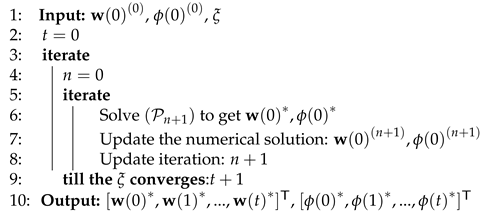
where and . Algorithm 1 outlines the SCA-based approach to solve Equation (12). It is noted that is a typical SOCP problem, and it can be effectively solved by the 10.1.28 version of MOSEK [31].
Furthermore, in order to replace , slack variables are introduced into the target function in . is defined as . Then the size of the optimization variables (in the real domain) is , while the overall number of second-order cone restrictions is . The overall complexity of the SOCP-based scheme in [32] at each iteration is given by as follows.
In practice, a considerable quantity of units are contained in the RIS: [33,34]. Therefore, iteration complexity of the recommended SOCP-based scheme is: .
| Algorithm 1. Proposed SOCP time-varying scheme To solve (12) |
 |
4. Numerical Results and Discussions
In our simulation experiments, the centre frequency of the system is 2 GHz, and the overall usable bandwidth is 20 MHz. For ease of calculation, the centre of the Tx antenna arrays is positioned at , with a velocity being and an azimuth angle being . The planar array centre of RIS is located at with an adjacent spacing of . Users with a single antenna are randomly dispersed in a region with the centre of the circle at . A radius of 5 is provided, with a minimum spacing being . The distributed small-scale Rician fading is modeled for the links based on [35]. The noise power spectral density for each antenna node is assumed to be −170 dBm/Hz, and the path loss exponent is 2. For ease of calculation, we suppose that for all . The target SINR is set to be 20 dB. When the target SINR is relatively low, it is easier to satisfy the SINR constraint and similar performance may be achieved by different optimisation schemes. Thus, more stringent SINR requirements are considered in the simulations.
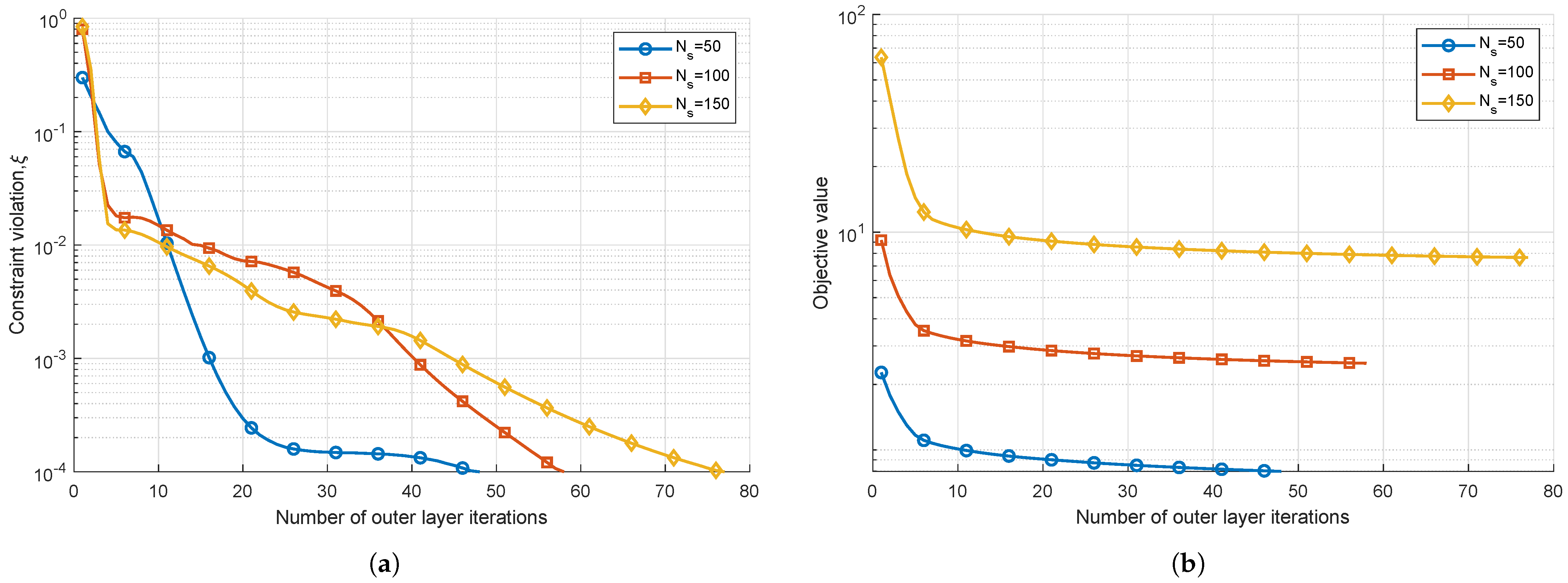
The convergence behavior of Algorithm 1 is analyzed for different number of RIS reflection elements when , , and . As illustrated in Figure 3a, the constraint violation parameter converges rapidly towards the transmit power. For all values of , is reached when the iteration value is 70∼75, and thus, the predefined accuracy is ensured. The constraint Equation (12) is essentially satisfied at the optimal solution. This is achieved by normalizing the channel coefficients and the noise power. Furthermore, as depicted in Figure 3b, the objective value of Equation (12) converges rapidly under different values of , so the effectiveness of Algorithm 1 is verified.
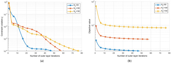
Figure 3.
Convergence behavior when and : (a) constraint violation; (b) objective value.
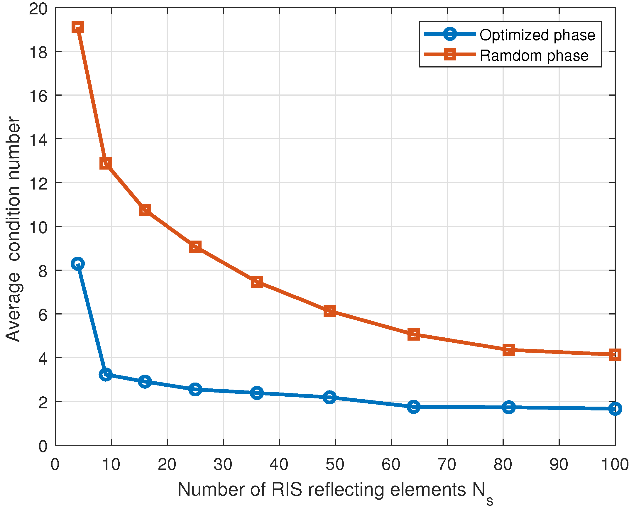
Figure 4 depicts the correlation between the standard condition number of and . The condition number can be described as the proportion between the largest and smallest eigenvalues. The performance is improved when the condition number approaches 1 [36]. Among the channels with the same total power gain, the channel with the highest capacity is the one with the same singular values. It is generally recognized that lower condition number signifies smaller distribution of singular values and higher capacity when SINR is high [37]. As shown in Figure 4, the condition number is reduced significantly with , and the capacity of the channel is approached in an almost well-conditioned state. Finally, it is concluded that the RIS can be effectively used to reconstructure the channel in large-scale complex networks. When the value of SINR is high, the disparity in each channel’s singular values can be decreased, and more channel throughput can be provided.
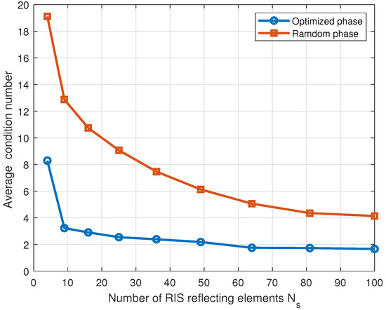
Figure 4.
Condition numbers versus when .
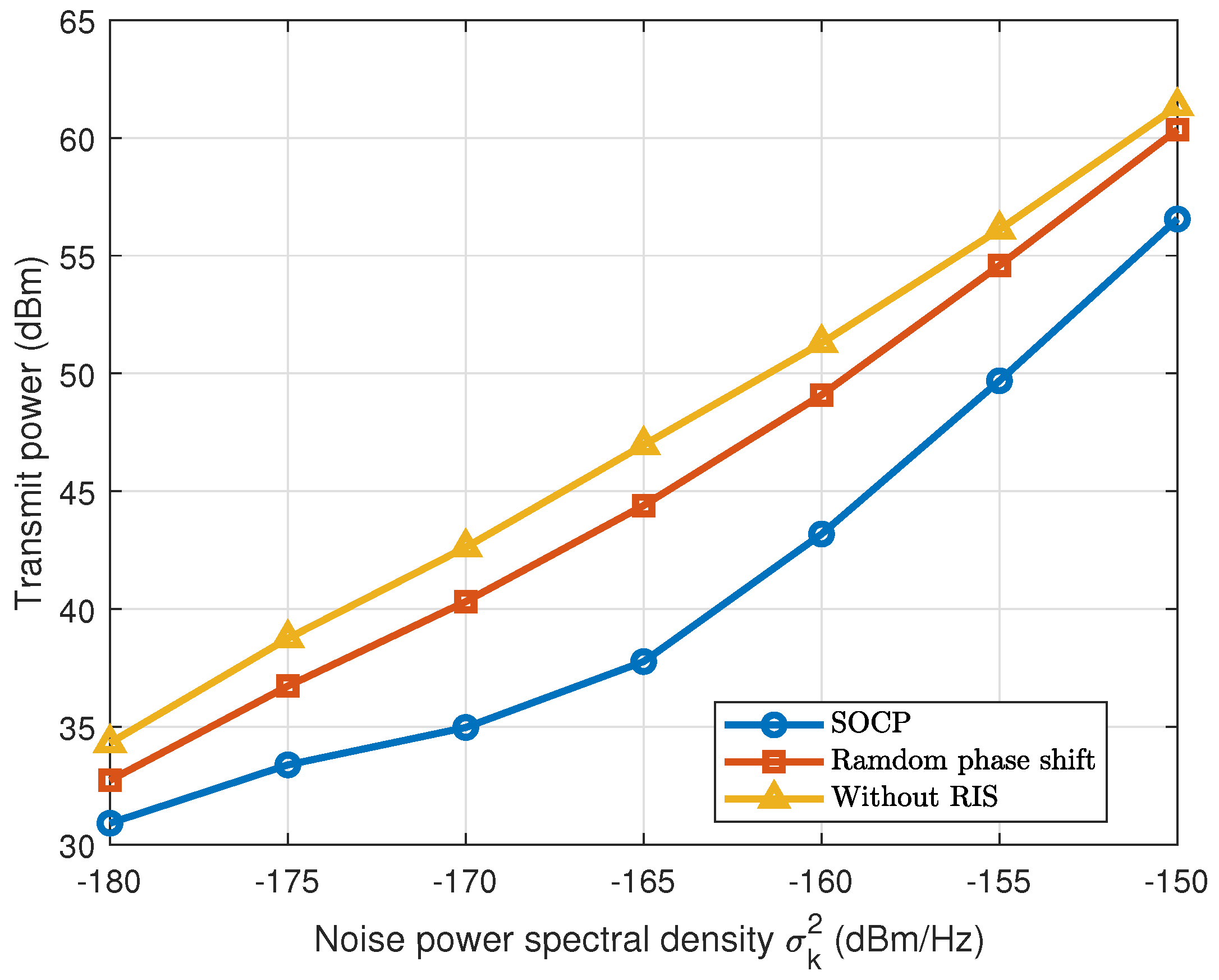
The performance of the transmission power versus the noise power is investigated in Figure 5. It is suggested that the transmit power is directly proportional to the increase of the noise power . When the noise power = −160 dBm, the transmit power is reduced by using the SOCP scheme in comparison to the conventional scheme with random phase shifts. The SOCP scheme has a power reduction of compared to the conventional scheme without RIS. Moreover, when the noise power is −160 dBm or below, the transmit power of SOCP is improved significantly, and can be reached the performance of the system with random phase shifts.
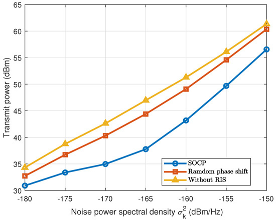
Figure 5.
Transmit power versus noise power spectral density when .
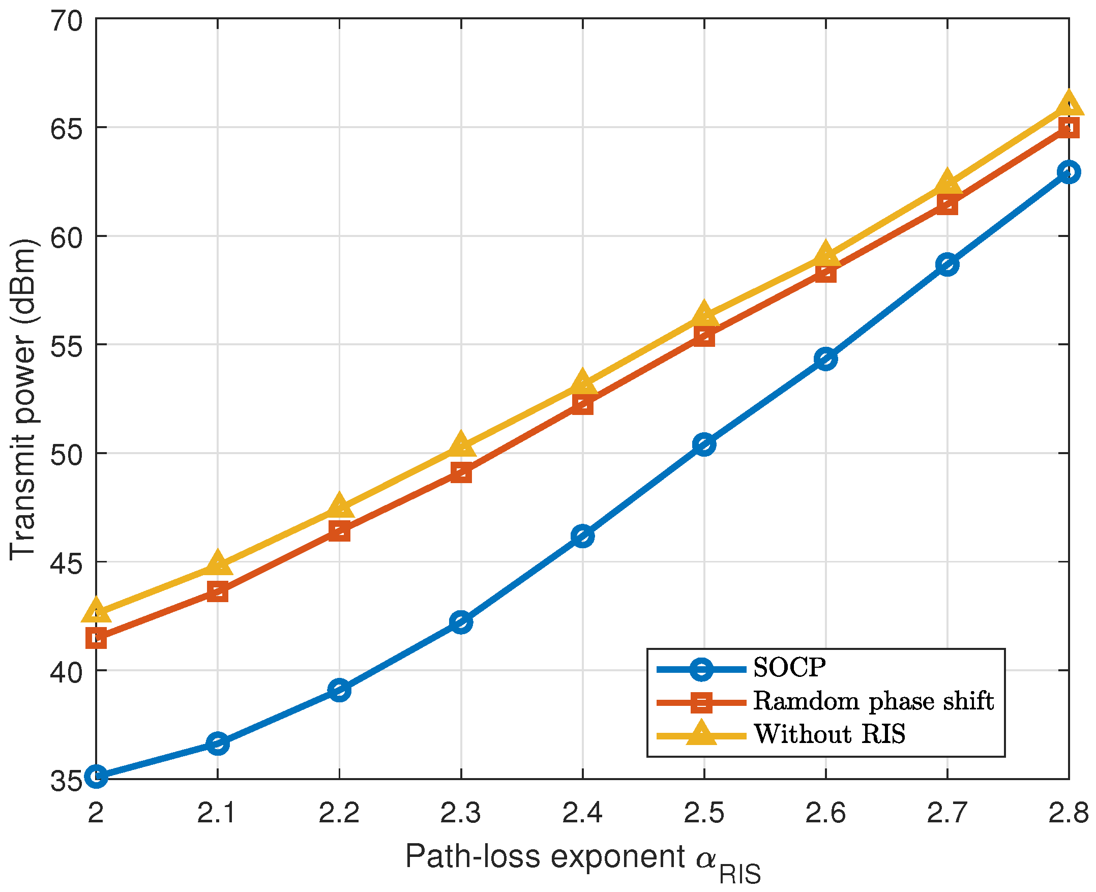
In order to ensure a rich scattering, it is necessary to increase the distance of the Tx-RIS link. However, it brings a larger path loss exponent [38]. The effect of the path loss exponent on the RIS- channel is illustrated in Figure 6. Firstly, it can be observed that when is small, a satisfactory average transmit power of SOCP is achieved. Secondly, when the value of grows, the average transmit power is increased, eventually approaching the scheme of random phase shift. The results suggest that to achieve both fairness and high system throughput, the path loss exponent should be reduced. That is to say, shorter distances and higher coefficient values are required. As a result, the possible spatial multiplexing benefits must be balanced against channel path loss.

Figure 6.
Transmit power versus path loss exponent when .
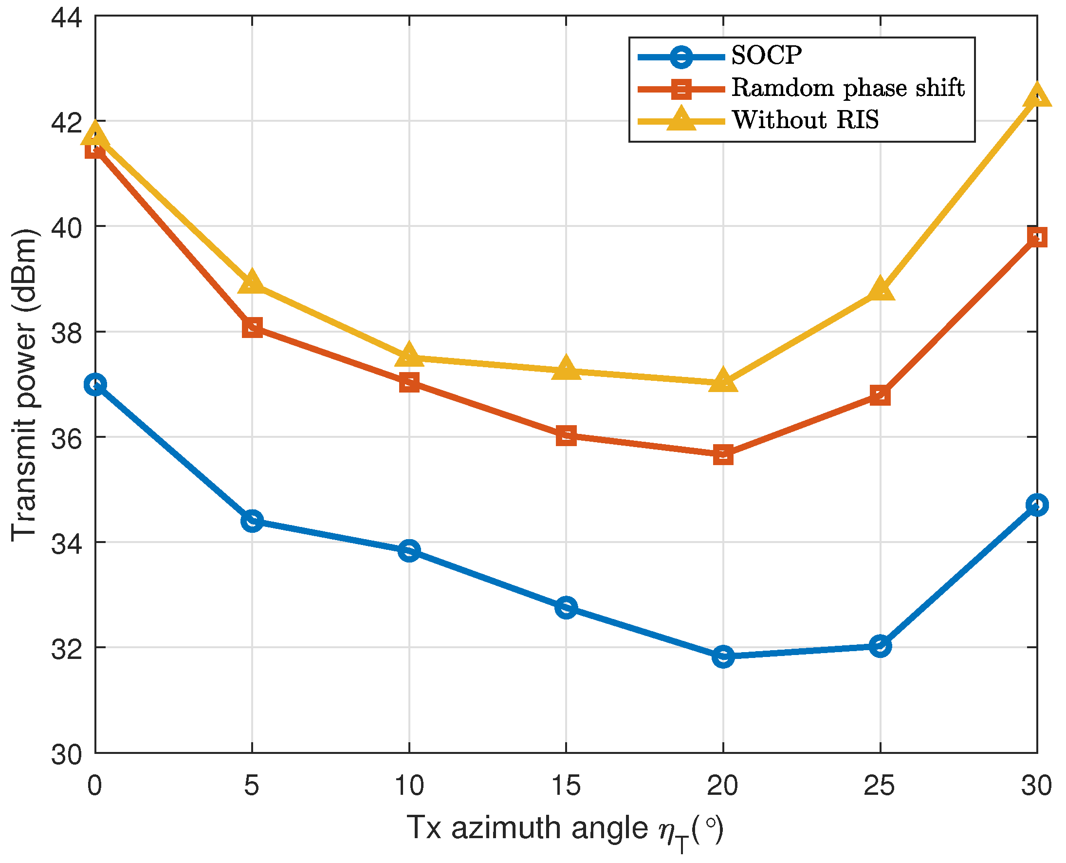
In Figure 7, the relationship between the transmit power and the azimuth angle is examined. It is discovered that when the angle rises, the SOCP scheme’s transmit power is fisrt reduced and then increased. In particular, when the azimuth angle , the transmit power of SOCP is reduced by compared to the conventional scheme with random phase shift and by to the scheme without RIS. These results indicate that to achieve a lower transmit power, it is also critical to choose a suitable azimuth angle . In this study, the best power reduction is achieved by an azimuth angle of about .
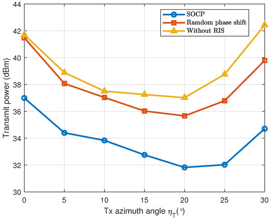
Figure 7.
Transmit power versus Tx azimuth angle when .
In Figure 8, the x-axis coordinate of is constant, and the relationship between the transmit power and the Tx- distance is investigated. It is observed that when the y-axis coordinate is , of the transmit power is saved by the SOCP scheme with respect to the conventional scheme of random phase shifting. In systems without RIS, especially when is far from Tx, the transmit power is significantly high due to signal damping. However, in RIS-assisted MU-MISO systems, the transmit power is initially increased and subsequently reduced with the horizontal distance.
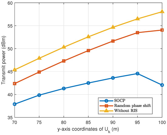
Figure 8.
Transmit power versus y-axis coordinates of when .
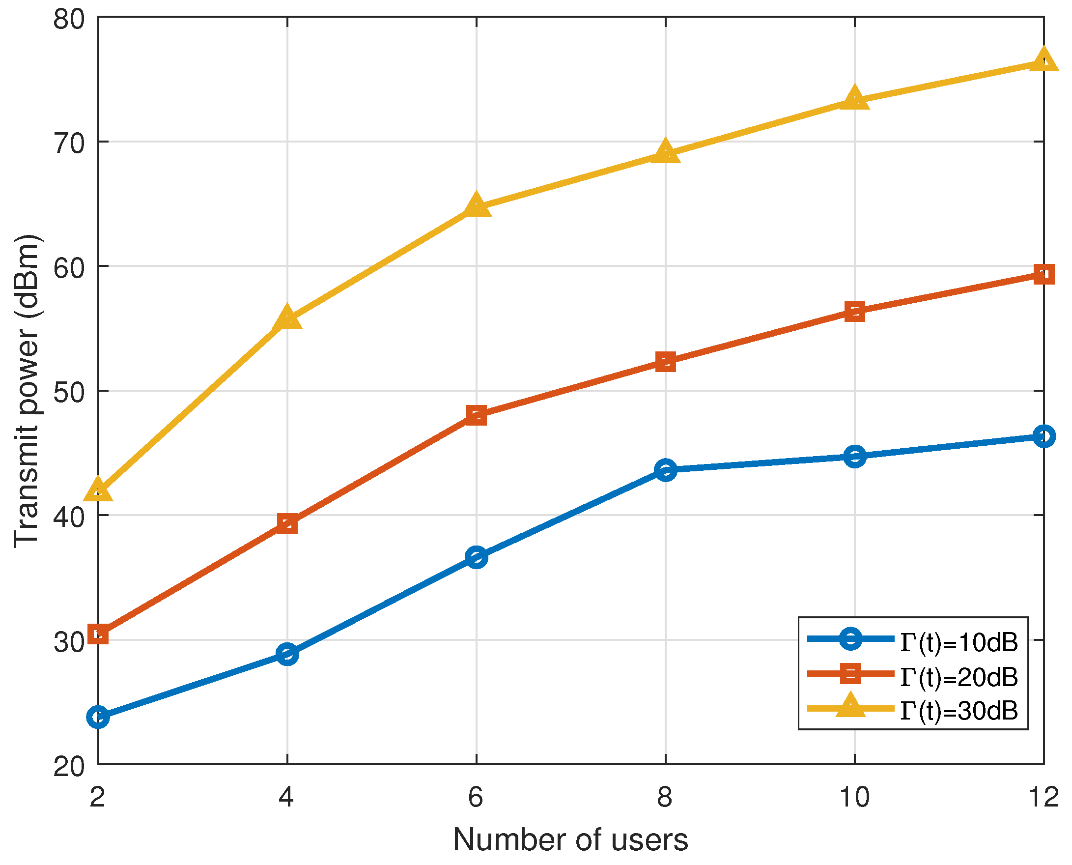
The influence of K on the transmit power is shown in Figure 9. To achieve the required QoS, the transmit power is increased sharply with the growth of K. With increasing values of K, the total interference power received by the users is increased, making it difficult for the achievement of the required QoS. It is shown that system coverage and performance may be enhanced by increasing transmit power. However, a larger K leads to an increase in the level of interference, which consequently deteriorates the user experience. Therefore, a balance must be established between transmit power and interference management to ensure the effective QoS.
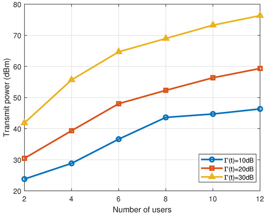
Figure 9.
Transmit power versus K when .
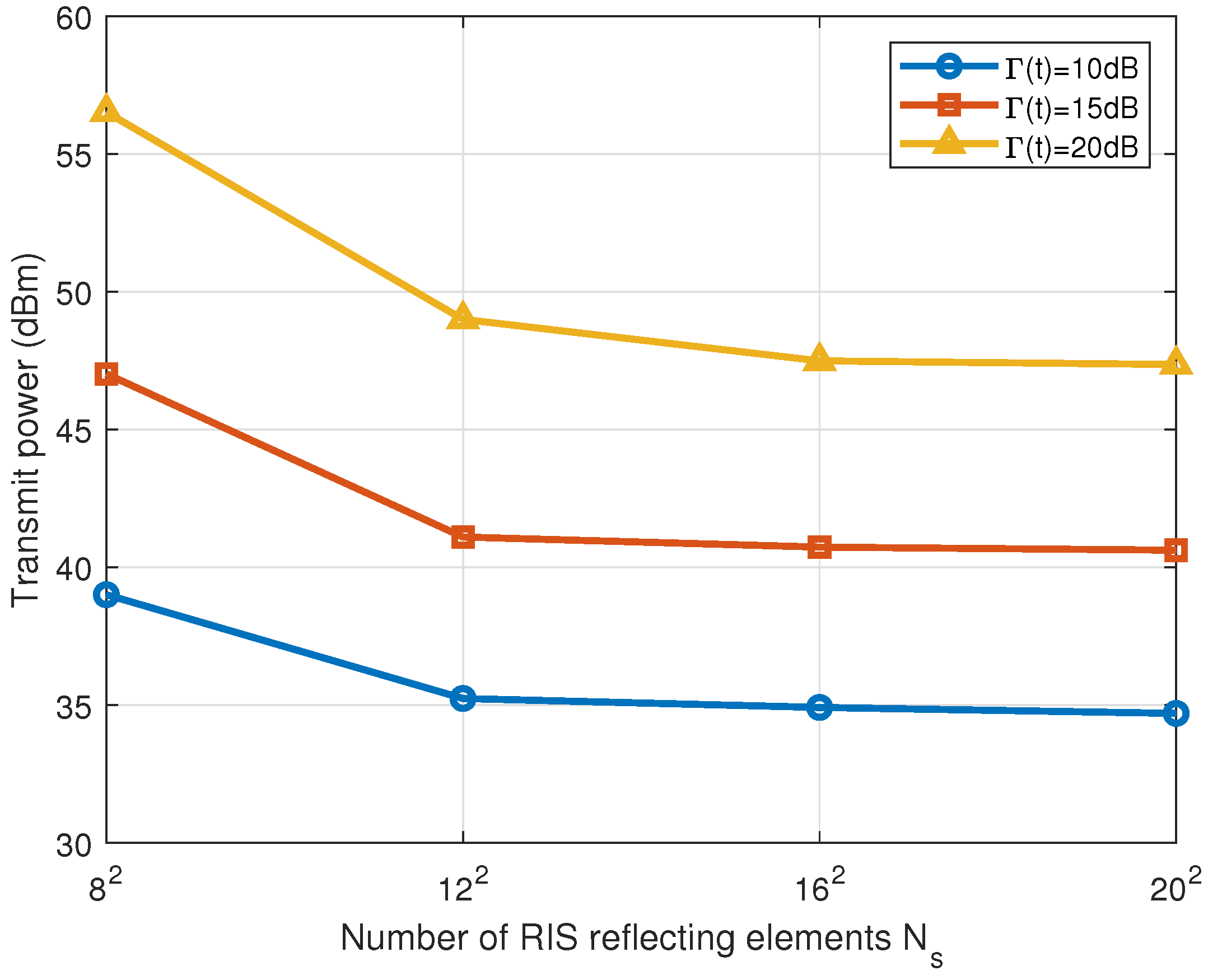
Figure 10 shows the correlation between the transmit power and . As increases, the transmit power required to maintain the required QoS is decreased. With a larger value of , the RIS can achieve the beamforming that is highly focused, allowing the required QoS to be enabled at low transmit power levels. On the other hand, when is small, higher transmit power is necessary to compensate for the signal loss and interference effects in order to ensure the communication quality.
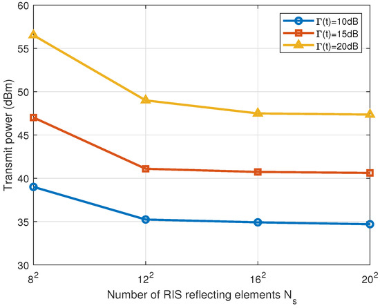
Figure 10.
Transmit power versus when .
Figure 11 depicts the convergence process using the SOCP time-varying algorithm. The vehicle trajectory is simulated over a time span of 0 to 4 seconds, with one state updated at every second. The simulation curve reveals that the transmit power is increased slightly after each update, although the overall trend is found to be downward. This trend is represented by the SOCP algorithm, which gradually decreases transmission power during the optimization phase to achieve the intended result. With this dynamic approach to optimisation, the beamforming of the system can be dynamically adjusted based on the vehicle’s real-time position and environmental conditions. Finally, the transmit power reduced while the required communication quality and service level are maintained at all times.
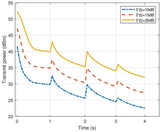
Figure 11.
Results of convergence when and during the time period of 0–4 s.
5. Conclusions
In this paper, a 3D time-varying channel model is proposed for the RIS-assisted MU-MISO systems. The goal is to decrease the transmit power while maintaining QoS requirements. More precisely, the proposed time-varying SOCP algorithm utilizes the SCA to update both transmit beamforming and phase shift variations at each iteration. It aims to achieve a more efficient numerical solution for the PowerMin problem. According to the findings of simulation results, the proposed SOCP algorithm is converged quickly and the transmit power is significantly reduced. Stable and high-quality communication in the scenario of high-speed vehicle movement can be achieved by adapting channel changes in real time. This is of tremendous relevance for enhancing the communication performance between high-speed vehicles and users, and is predicted to tackle comparable challenges in RIS-assisted communication systems.
Author Contributions
Conceptualization, F.Y.; Investigation, F.Y.; Methodology, F.Y.; Resources, F.Y.; Software, F.Y. and S.L.; Supervision, T.L.; Writing—original draft, F.Y. and S.L.; Writing—review and editing, T.L. All authors have read and agreed to the published version of the manuscript.
Funding
This research received no external funding.
Data Availability Statement
Data are contained within the article.
Conflicts of Interest
The authors declare no conflicts of interest.
References
- Zhang, Z.; Xiao, Y.; Ma, Z.; Xiao, M.; Ding, Z.; Lei, X.; Karagiannidis, G.K.; Fan, P. 6G wireless networks: Vision, requirements, architecture, and key technologies. IEEE Veh. Technol. Mag. 2019, 14, 28–41. [Google Scholar] [CrossRef]
- Zhang, J.H.; Tang, P.; Yu, L.; Jiang, T.; Tian, L. Channel measurements and models for 6G: Current status and future outlook. Front. Inf. Technol. Electron. Eng. 2020, 21, 39–61. [Google Scholar] [CrossRef]
- Yang, H.; Cao, X.; Yang, F.; Gao, J.; Xu, S.; Li, M.; Chen, X.; Zhao, Y.; Zheng, Y.; Li, S. A programmable metasurface with dynamic polarization, scattering and focusing control. Sci. Rep. 2016, 6, 35692. [Google Scholar] [CrossRef] [PubMed]
- Di Renzo, M.; Zappone, A.; Debbah, M.; Alouini, M.S.; Yuen, C.; De Rosny, J.; Tretyakov, S. Smart radio environments empowered by reconfigurable intelligent surfaces: How it works, state of research, and the road ahead. IEEE J. Sel. Areas Commun. 2020, 38, 2450–2525. [Google Scholar] [CrossRef]
- Pan, C.; Ren, H.; Wang, K.; Kolb, J.F.; Elkashlan, M.; Chen, M.; Di Renzo, M.; Hao, Y.; Wang, J.; Swindlehurst, A.L.; et al. Reconfigurable intelligent surfaces for 6G systems: Principles, applications, and research directions. IEEE Commun. Mag. 2021, 59, 14–20. [Google Scholar] [CrossRef]
- Wu, Q.; Zhang, R. Towards smart and reconfigurable environment: Intelligent reflecting surface aided wireless network. IEEE Commun. Mag. 2019, 58, 106–112. [Google Scholar] [CrossRef]
- Wu, Q.; Zhang, R. Intelligent reflecting surface enhanced wireless network via joint active and passive beamforming. IEEE Trans. Wirel. Commun. 2019, 18, 5394–5409. [Google Scholar] [CrossRef]
- Zhang, S.; Zhang, R. Capacity characterization for intelligent reflecting surface aided MIMO communication. IEEE J. Sel. Areas Commun. 2020, 38, 1823–1838. [Google Scholar] [CrossRef]
- Guo, H.; Liang, Y.C.; Chen, J.; Larsson, E.G. Weighted sum-rate maximization for intelligent reflecting surface enhanced wireless networks. In Proceedings of the 2019 IEEE Global Communications Conference (GLOBECOM), Waikoloa, HI, USA, 9–13 December 2019; pp. 1–6. [Google Scholar]
- Li, S.; Duo, B.; Yuan, X.; Liang, Y.C.; Renzo, M.D. Reconfigurable intelligent surface assisted UAV communication: Joint trajectory design and passive beamforming. IEEE Wirel. Commun. Lett. 2020, 9, 716–720. [Google Scholar] [CrossRef]
- Chang, D.; Jiang, H.; Zhou, J.; Zhang, H.; Mukherjee, M. Capacity optimization using augmented lagrange method in intelligent reflecting surface-based MIMO communication systems. China Commun. 2020, 17, 123–138. [Google Scholar] [CrossRef]
- Ruan, C.; Zhang, Z.; Jiang, H.; Dang, J.; Wu, L.; Zhang, H. Approximate message passing for channel estimation in reconfigurable intelligent surface aided MIMO multiuser systems. IEEE Trans. Commun. 2022, 70, 5469–5481. [Google Scholar] [CrossRef]
- Liu, T.; Yang, X.; Jiang, H.; Zhang, H.; Chen, Z. Reconfigurable intelligent surface enhanced massive connectivity with massive MIMO. IEEE Trans. Commun. 2023, 71, 7441–7454. [Google Scholar] [CrossRef]
- Liu, T.; Jiang, H.; Yang, Z.; Chen, Z. Reconfigurable intelligent surface enhanced massive IoT systems with nonlinear measurements. IEEE Wirel. Commun. Lett. 2023, 12, 1976–1980. [Google Scholar] [CrossRef]
- Cui, M.; Zhang, G.; Zhang, R. Secure wireless communication via intelligent reflecting surface. IEEE Wirel. Commun. Lett. 2019, 8, 1410–1414. [Google Scholar] [CrossRef]
- Di Renzo, M.; Ntontin, K.; Song, J.; Danufane, F.H.; Qian, X.; Lazarakis, F.; De Rosny, J.; Phan-Huy, D.T.; Simeone, O.; Zhang, R.; et al. Reconfigurable intelligent surfaces vs. relaying: Differences, similarities, and performance comparison. IEEE Open J. Commun. Soc. 2020, 1, 798–807. [Google Scholar] [CrossRef]
- Yang, Z.; Xu, W.; Huang, C.; Shi, J.; Shikh-Bahaei, M. Beamforming design for multiuser transmission through reconfigurable intelligent surface. IEEE Trans. Commun. 2020, 69, 589–601. [Google Scholar] [CrossRef]
- Liu, Y.; Zhao, J.; Li, M.; Wu, Q. Intelligent reflecting surface aided MISO uplink communication network: Feasibility and power minimization for perfect and imperfect CSI. IEEE Trans. Commun. 2020, 69, 1975–1989. [Google Scholar] [CrossRef]
- Wu, J.; Shim, B. Power minimization of intelligent reflecting surface-aided uplink IoT networks. In Proceedings of the 2021 IEEE Wireless Communications and Networking Conference (WCNC), Nanjing, China, 29 March–1 April 2021; pp. 1–6. [Google Scholar]
- Kumar, V.; Zhang, R.; Di Renzo, M.; Tran, L.N. A novel SCA-based method for beamforming optimization in IRS/RIS-assisted MU-MISO downlink. IEEE Wirel. Commun. Lett. 2022, 12, 297–301. [Google Scholar] [CrossRef]
- Xiong, B.; Zhang, Z.; Jiang, H.; Zhang, H.; Zhang, J.; Wu, L.; Dang, J. A statistical MIMO channel model for reconfigurable intelligent surface assisted wireless communications. IEEE Trans. Commun. 2021, 70, 1360–1375. [Google Scholar] [CrossRef]
- Jiang, H.; Ruan, C.; Zhang, Z.; Dang, J.; Wu, L.; Mukherjee, M.; da Costa, D.B. A general wideband non-stationary stochastic channel model for intelligent reflecting surface-assisted MIMO communications. IEEE Trans. Wirel. Commun. 2021, 20, 5314–5328. [Google Scholar] [CrossRef]
- Xiong, B.; Zhang, Z.; Jiang, H. Reconfigurable intelligent surface for mmWave mobile communications: What if LoS path exists? IEEE Wirel. Commun. Lett. 2022, 12, 247–251. [Google Scholar] [CrossRef]
- Jiang, H.; Xiong, B.; Zhang, H.; Basar, E. Hybrid Far- and Near-Field Modeling for Reconfigurable Intelligent Surface Assisted V2V Channels: A Sub-Array Partition Based Approach. IEEE Trans. Wirel. Commun. 2023, 22, 8290–8303. [Google Scholar] [CrossRef]
- Xiong, B.; Zhang, Z.; Jiang, H.; Zhang, J.; Wu, L.; Dang, J. A 3D non-stationary MIMO channel model for reconfigurable intelligent surface auxiliary UAV-to-ground mmWave communications. IEEE Trans. Wirel. Commun. 2022, 21, 5658–5672. [Google Scholar] [CrossRef]
- Jiang, H.; He, R.; Ruan, C.; Zhou, J.; Chang, D. Three-dimensional geometry-based stochastic channel modeling for intelligent reflecting surface-assisted UAV MIMO communications. IEEE Wirel. Commun. Lett. 2021, 10, 2727–2731. [Google Scholar] [CrossRef]
- Jiang, H.; Zhang, Z.; Xiong, B.; Dang, J.; Wu, L.; Zhou, J. A 3D stochastic channel model for 6G wireless double-IRS cooperatively assisted MIMO communications. In Proceedings of the 2021 13th International Conference on Wireless Communications and Signal Processing (WCSP), Changsha, China, 20–22 October 2021; pp. 1–5. [Google Scholar]
- Jiang, H.; Xiong, B.; Zhang, H.; Basar, E. Physics-based 3D end-to-end modeling for double-RIS assisted non-stationary UAV-to-ground communication channels. IEEE Trans. Commun. 2023, 71, 4247–4261. [Google Scholar] [CrossRef]
- Han, H.; Zhao, J.; Zhai, W.; Xiong, Z.; Niyato, D.; Di Renzo, M.; Pham, Q.V.; Lu, W.; Lam, K.Y. Reconfigurable intelligent surface aided power control for physical-layer broadcasting. IEEE Trans. Commun. 2021, 69, 7821–7836. [Google Scholar] [CrossRef]
- Wu, Q.; Zhang, S.; Zheng, B.; You, C.; Zhang, R. Intelligent reflecting surface-aided wireless communications: A tutorial. IEEE Trans. Commun. 2021, 69, 3313–3351. [Google Scholar] [CrossRef]
- ApS, M. MOSEK Fusion API for Python. Release 10.1.28. Available online: https://docs.mosek.com/10.1/pythonfusion.pdf (accessed on 11 March 2024).
- Ben-Tal, A.; Nemirovski, A. Modern Convex Optimization; The William Da vidson Faculty of Industrial Engineering and Management, Technion–Israel Institute of Technology: Haifa, Israel, 2013. [Google Scholar]
- Dai, L.; Wang, B.; Wang, M.; Yang, X.; Tan, J.; Bi, S.; Xu, S.; Yang, F.; Chen, Z.; Di Renzo, M.; et al. Reconfigurable intelligent surface-based wireless communications: Antenna design, prototyping, and experimental results. IEEE Access 2020, 8, 45913–45923. [Google Scholar] [CrossRef]
- Pei, X.; Yin, H.; Tan, L.; Cao, L.; Li, Z.; Wang, K.; Zhang, K.; Björnson, E. RIS-aided wireless communications: Prototyping, adaptive beamforming, and indoor/outdoor field trials. IEEE Trans. Commun. 2021, 69, 8627–8640. [Google Scholar] [CrossRef]
- Perović, N.S.; Tran, L.N.; Di Renzo, M.; Flanagan, M.F. On the maximum achievable sum-rate of the RIS-aided MIMO broadcast channel. IEEE Trans. Signal Process. 2022, 70, 6316–6331. [Google Scholar] [CrossRef]
- Matthaiou, M.; McKay, M.R.; Smith, P.J.; Nossek, J.A. On the condition number distribution of complex Wishart matrices. IEEE Trans. Commun. 2010, 58, 1705–1717. [Google Scholar] [CrossRef]
- Tse, D.; Viswanath, P. Fundamentals of Wireless Communication; Cambridge University Press: Cambridge, UK, 2005. [Google Scholar]
- 3rd Generation Partnership Project (3GPP). Spatial Channel Model for Multiple Input Multiple Output (MIMO) Simulations; Tech. Rep. TR 25.996; 3GPP: Brussels, Belgium, 2012. [Google Scholar]


Disclaimer/Publisher’s Note: The statements, opinions and data contained in all publications are solely those of the individual author(s) and contributor(s) and not of MDPI and/or the editor(s). MDPI and/or the editor(s) disclaim responsibility for any injury to people or property resulting from any ideas, methods, instructions or products referred to in the content. |
© 2024 by the authors. Licensee MDPI, Basel, Switzerland. This article is an open access article distributed under the terms and conditions of the Creative Commons Attribution (CC BY) license (https://creativecommons.org/licenses/by/4.0/).