Article

Wideband Eight-Antenna Array Designs for 5G Smartphone Applications

by
Guan-Long Huang
1,
Ting-Yu Chang
2 and
Chow-Yen-Desmond Sim
2,*
1
Guangdong Provincial Key Laboratory of Industrial Intelligent Inspection: Technology, The School of Electronic and Information Engineering, Foshan University, Foshan 528225, China
2
Department of Electrical Engineering, Feng Chia University, Taichung 40724, Taiwan
*
Author to whom correspondence should be addressed.
Electronics 2024, 13(15), 2995; https://doi.org/10.3390/electronics13152995 (registering DOI)
Submission received: 4 June 2024 / Revised: 11 July 2024 / Accepted: 17 July 2024 / Published: 29 July 2024
(This article belongs to the Special Issue Advanced Antenna Technologies for B5G and 6G Applications)

Abstract

:
This paper proposes a broadband eight-antenna array design suitable for Fifth Generation New Radio (5G NR) smartphone applications. To cover the 5G NR bands n77/n78/n79 (3300–5000 MHz) and 5G NR-U n46 band (5150–5925 MHz), the single antenna array unit applied is a modified loop antenna element (MLAE) that can generate three different loop modes. To yield good multi-input multi-output (MIMO) performances, the designed MLAE is further arranged as an eight-antenna array, and the experimental results show that the overlapping 6 dB bandwidth can cover the bands-of-interest (3300–5925 MHz) with good isolation and total efficiency of >10 dB and 51–84%, respectively. Finally, good MIMO performances, such as an envelope correlation coefficient (ECC) of lower than 0.1 and desirable channel capacity (CC) of 37–40 bps/Hz, were calculated across the bands-of-interest.

1. Introduction

In today’s modern society, the construction of Fifth Generation (5G) Mobile Communication is gradually being completed. Due to the increasing demands for data throughput and bandwidth utilization from technologies such as the Internet of Things (IoT), electric vehicles, and smart-home appliances, the bandwidth provided by Fourth Generation Mobile (4G) Communication is inadequate to fulfill the demands of the market. To enable higher data transmission within the 5G bands, MIMO technology has become crucial in smartphone and base station technology. Additionally, MIMO technology can effectively enhance spectrum utilization and channel capacity (CC) [1,2]. In 2018, the 3rd Generation Partnership Project (3GPP) officially defined the specifications for 5G NR Release 15 [3]. According to these specifications, 5G NR in the sub-6 GHz range includes three operating bands: Band n77 (3.3–4.2 GHz), Band n78 (3.3–3.8 GHz), and Band n79 (4.4–5.0 GHz). Consequently, countries around the world have selected their respective 5G bands from these frequencies.
With the increasing market and technological demands, not only the aforementioned licensed bands, but also the application of an unlicensed spectrum has gained significant attention. The main relevant frequency band for this is the Unlicensed National Information Infrastructure (U-NII) band, and corresponding to this band, LTE Band 46 has been proposed. In 2020, 3GPP officially introduced Release 16 [4], which highlights the 5G New Radio Unlicensed (5G NR-U) band. This unlicensed band is due to the development of the unlicensed spectrum LTE-U (LTE in Unlicensed Spectrum) and Licensed-Assisted Access (LAA) from 3GPP Release 13/14. As a result, NR-U equipment will operate within 6 GHz band for the first time. In the United States, the NR-U is divided into four sub-bands, namely, U-NII-5 to U-NII-8 (5925–7125 MHz), and is classified as the new version of Wi-Fi, widely known as Wi-Fi 6E. Finally, 3GPP’s Release 16 officially added the LTE Band 46 (5.15–5.925 GHz) to the 5G NR FR 1, designated as 5G NR-U n46; the 5.925–7.125 GHz band is designated as 5G NR-U n96.
In the early designs of 5G mobile phone antennas, to induce a resonance mode at 3.5 GHz, a common approach was to etch an open-slot antenna with a length of λ/4 in the ground plane [5,6,7] or to generate a quarter-wavelength mode using a monopole antenna [8]. However, present smartphone antennas are often collocated along the phone’s frame, leading some researchers to design inverted-F antennas (IFAs) [9] and loop antennas [10] on the frame to excite a 3.5 GHz mode. However, narrowband antennas for smartphone applications are no longer sufficient to meet the market demands. Consequently, many papers have reported combined IFAs and loop antennas to form hybrid antenna designs [11,12,13], which can produce dual-band or wideband modes. In the limited space of a smartphone, accommodating multiple antennas presents a significant challenge for maintaining isolation between antennas.
Various methods to improve isolation have been proposed in the open literature; for instance, decoupling structures [14,15,16,17,18,19,20,21] can effectively reduce the coupling energy between antennas, and orthogonal polarization [22,23,24,25,26,27] uses polarization diversity to enhance antenna isolation. Besides the above techniques, the self-isolated designs [28,29,30,31,32,33] can also improve isolation efficiency by reducing the impact of ground plane currents. For example, [31] capture currents on the ground plane of the antenna (wave trap) to minimize the influence on adjacent antennas, while [32,33] found that symmetric structures effectively reduce the ground plane current, thereby lowering interference between antennas. Notably, the work in [34] points out that the antenna feed position affects isolation performance, suggesting that placing antennas at current null points can improve isolation. Additionally, [35] mentions that adding capacitors or inductors between adjacent antennas can effectively eliminate the coupling.
As stated in [36], the construction of 5G mobile communication infrastructure for the sub-6 GHz band has been gradually completed in many developed countries. To achieve higher data throughput in the 5G operating frequency bands below the sub-6 GHz band, one of the leading 5G technologies is MIMO technology, which plays a pivotal role in both smartphone and base station technology. As aforementioned, many single-band or dual-band operation MIMO antenna arrays have been investigated for 5G smartphones; however, these antenna designs can only cover part of the 5G bands (3300–5000 MHz). Therefore, it is vital to implement a wideband operation 5G MIMO antenna array design that can cover the 5G bands of interest [37,38,39,40,41,42,43,44,45,46]. In [38,39,40], MIMO antenna array designs for metallic frames are adopted. In [38,39], an open slot is cut into a metallic frame with an extended slot loaded into the ground plane, and an additional tuning stub is implemented to achieve a good 6 dB overlapped impedance bandwidth across the bands-of-interest. In comparison, [40] requires two slots (inverted T-shaped and inverted C-shaped) to be loaded into the metallic frame, and these slots are fed by a meticulously designed L-shaped feed-line.
Besides applying antenna array structures with metallic frames, other designs have been explored. In [41], the individual array element consists of an inverted-F antenna with shorting branches and parasitic elements. Impedance matching for the mid-band at 5.2 GHz can be fine-tuned using an L-shaped parasitic element and a slot. In [42], an inverted-F antenna (IFA) unit structure is implemented for 4 × 4 MIMO operation, and it is coupled-fed by a meandering line coupled feeding structure. Notably, a 4 × 4 MIMO operation IFA pair is also implemented in [43], featuring a two-antenna conjoined type with two identical IFA structures (back-to-back) linked to the same grounding structure. However, [43] only applied the IFA pair for 4 × 4 MIMO operation, and such a design requires the excitation of three different modes (loop, IFA, and slot) to achieve wideband operation, resulting in diverse radiation patterns across the bands-of-interest. Compared to the IFA pair design in [43,44], a different integrated slot antenna pair for 8 × 8 MIMO operation is implemented. This design employs a dual-mode decoupling technique specifically for closely spaced open-slot antennas, but a horizontal connecting line must be used to link the two open-slot antennas to achieve desirable isolation of >10.8 dB.
In this paper, a modified loop antenna element (MLAE) is proposed as the antenna unit for an 8 × 8 MIMO antenna array. This MLAE design is derived from a modified loop antenna type fed by a T-shaped coupled feeding structure [46]. However, the loop antenna in [45] could only excite a fundamental loop mode, resulting in a narrow operating bandwidth of 3400–3600 MHz. To achieve a better impedance bandwidth, the design in [46] was further modified into a wideband loop antenna. This wideband design was achieved by disassembling the loop antenna into four sections and applying a coupling method, where two sections located on one side of the substrate are coupled to the two collocated on the other side. This reconfigures the loop antenna into a segmented coupled loop antenna type. By applying this method, the coupling structure can excite an additional 0.75-wavelength loop mode. Combining this mode with the 0.5-wavelength fundamental loop mode and the 1.0-wavelength higher resonant loop mode yields a wideband operation covering the 5G bands-of-interest (3300–5925 MHz). Nonetheless, to avoid the complexity of the segmented coupled loop antenna, which requires printing antenna structures on both sides of the substrate, we propose a novel MLAE, and its corresponding contributions are as follows:
  • It offers a streamlined manufacturing process and cost savings by printing the loop antenna structure solely on one side of the substrate. In comparison, the loop antenna described in [46] necessitates printing on both sides.
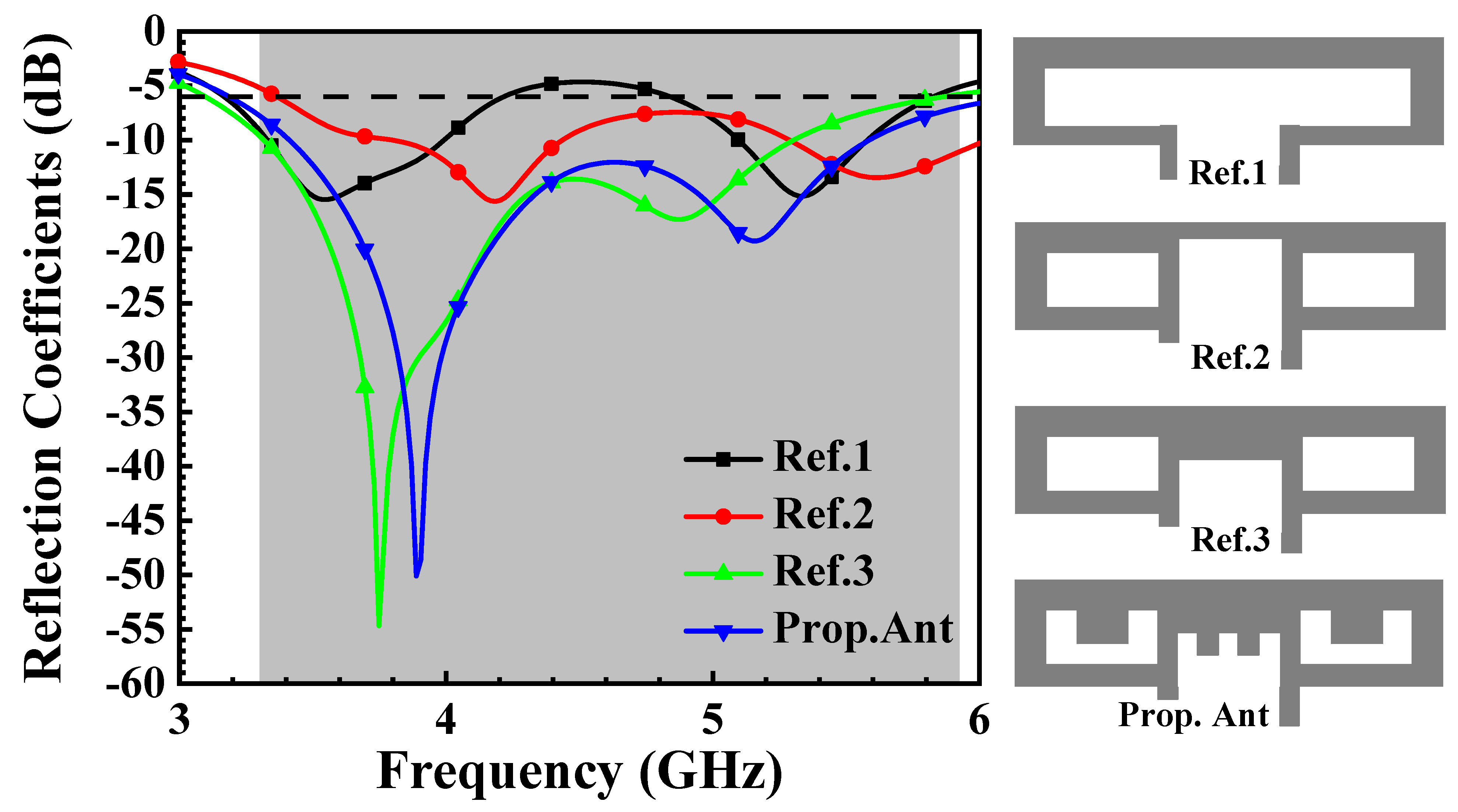
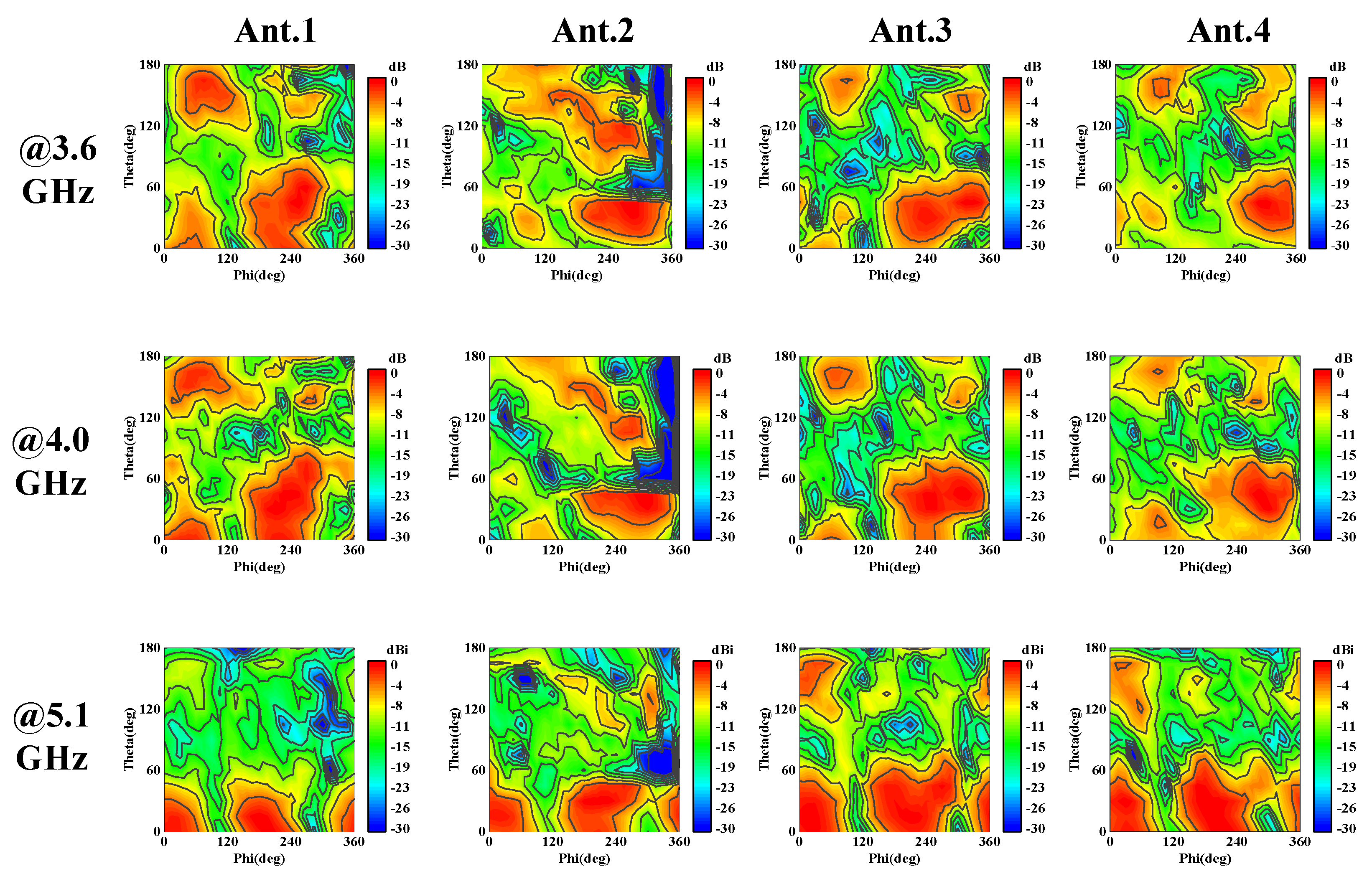
  • It can produce three distinct loop modes (at 3.6, 4.0, and 5.1 GHz), resulting in a broader operating band width compared to [46].
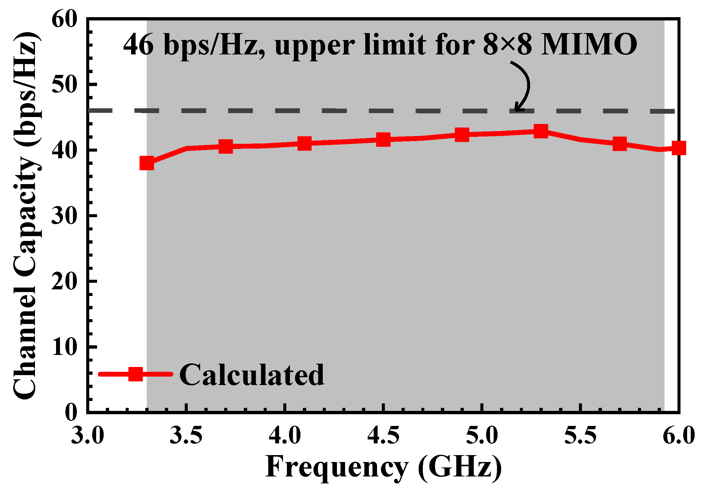
  • The CC demonstrated is an impressive 37–40 bps/Hz, just marginally below the theoretical upper limit of 46 bps/Hz.
Both the design methodology of the MLAE and the MIMO performance with an array of eight MLAEs are confirmed through simulation and experimental measurement.

2. Antenna Geometry and Design Evolution

Figure 1 depicts the MLAE antenna design, integrated on the inner side of the smartphone’s longer frame. The antenna, measuring 21 mm × 6 mm, is fed by a 50-ohm microstrip line at point F, with its loop structure grounded via shorting point S on the system ground plane beneath the substrate. This MLAE features a main structure comprising two P-type radiating elements arranged back-to-back, connected by a bridge and adorned with two protruding stubs, each measuring 1 mm (L1) × 0.8 mm, as shown in Figure 1. Notably, each P-type radiating element is loaded with a U-shaped slot (with parameter L2 = 1.5 mm), which excites the three loop modes (at 3.6, 4.0, and 5.1 GHz) to cover the bands-of-interest (3300–5925 MHz).
Figure 2 shows the proposed eight-antenna array, with four MLAEs arranged along each long side frame of the smartphone casing, maintaining a gap distance of 16.5 mm (d1 = d2 = d3) between any two MLAEs. The side frame measures 150 mm × 7 mm in area, while the system ground covers an area of 148 mm × 73 mm on a substrate that is 150 mm × 75.6 mm. The smartphone casing, including the frame and ground, is made of FR4 substrate of thickness 0.8 mm.
Figure 3 shows the design evolution of the proposed MLAE. It began with a simple conventional loop antenna structure (similar to [10]), denoted as Ref. 1, which can excite two distinct modes at 3.54 and 5.34 GHz. To enhance the operating bandwidth, Ref. 2 was constructed by reconfiguring the loop structure into two P-shaped elements (back-to-back) linked by a narrow bridge. In this configuration, besides the previous modes from Ref. 1 (shifted to 3.59 and 5.62 GHz), an additional middle mode at 4.19 GHz is also excited. However, as the lower frequency of Ref. 2 is at 3370 MHz, it is insufficient to cover the bands-of-interest (3300–5925 MHz). To further improve the matching of Ref. 2 and satisfy the bands-of-interest, the connected bridge of Ref. 2 was enlarged from 1.4 mm to 1.8 mm, denoted as Ref. 3. Although Ref. 3 excited three resonant modes at 3.7, 4.1, and 4.86 GHz, the upper frequency could not cover the high band of n46 (5925 MHz). Therefore, a rectangular slot forming the P-shaped element was reconfigured into a U-shaped type (with parameter L2), and two stubs (with parameter L1) were protruded from the connected bridge. This modification shifted the higher resonant mode from 4.86 to 5.10 GHz, while the lower and middle modes were slightly deviated to 3.6 and 4.0 GHz, respectively. Here, the proposed MLAE exhibits a desirable 6 dB bandwidth of 3.15–6.75 GHz, and the impedance matching is better as compared to the conventional loop antenna (Ref. 1).
Figure 4a,b illustrate the effects of fine-tuning the two parameters, L1 and L2. By linearly increasing the length of parameter L1 by 0.5 mm (0.5 to 1.5 mm), the three modes are also shifted linearly towards the higher spectrum, demonstrating that adjusting the length of L1 affects all resonant modes. In comparison, by linearly expanding the parameter L2 by 0.5 mm (1 to 2 mm), the middle resonant mode shifts to the lower spectrum and combines with the lower resonant mode, forming a dual resonant effect. Since fine-tuning L1 and L2 does not affect the overall impedance bandwidths of the proposed MLAE, we selected L1 = 1 mm and L2 = 1.5 mm as the optimum values.

3. Findings and Analysis

The front and back views of the fabricated eight-antenna array prototype are depicted in Figure 5. Figure 6a,b display the simulated reflection coefficient (return loss) and transmission coefficient (isolation) of the eight-antenna array. For brevity, we only investigate Ant.1 to Ant.4. Figure 6a shows that the stacked 6 dB bandwidth (S11, S22, S33, and S44) adequately covers the bands-of-interest (3300–5925 MHz). Regarding the transmission coefficients (S21, S32, and S43), good isolation levels better than 10 dB were achieved.
Figure 7a presents the measured reflection coefficients (S11, S22, S33, and S44) of the proposed eight-antenna array. It demonstrates that the array covers the bands-of-interest with a 74.1% (3100–6750 MHz) stacked 6 dB bandwidth. Figure 7b shows that the measured transmission coefficients (S21, S32, and S43) closely match the simulated results in Figure 6b. Notably, the simulated and measured data of the proposed array are well validated, with slight differences likely due to fabrication tolerances.
To further understand the excitation of the three loop modes in the proposed MLAE, Figure 8 illustrates the current distributions at 3.6, 4.0, and 5.1 GHz. The current path at 3.6 GHz represents a half-wavelength (0.5λ loop mode) distribution that flows from the feeding point F to the shorting point S, passing through a null point at the right upper corner of the P-shaped element. At 4.0 GHz, the current flows from the feeding point F to the P-shaped element (located on the left side of the MLAE), reaching a null point before returning to the shorting point S. This forms another half-wavelength (0.5λ loop mode) distribution. Lastly, at 5.1 GHz, the current path follows a conventional one-wavelength (1λ loop mode) distribution, extending from point F to point S via the connected bridge, with null points located at both ends of the P-shaped elements.
Figure 9 is a photo of the proposed eight-antenna array placed in an anechoic chamber for measurement. The simulated and measured total efficiencies of the proposed array (Ant.1–Ant.4) are shown in Figure 10a,b, respectively. Ant.2 and Ant.3, positioned at the center of the array, exhibit slightly lower efficiencies due to the influence of adjacent antennas, compared to the outer elements (Ant.1–Ant.4). Despite this, the total efficiencies of all elements remain robust across the bands-of-interest, with simulated values ranging from 62% to 85% and measured values from 51% to 84%. These performance levels meet the typical standards (>40%) required for practical smartphone applications.
Figure 11a–c display the normalized radiation patterns of the proposed array (Ant.1–Ant.4) at 3.6, 4.0, and 5.1 GHz. The radiation patterns of Ant.1 and Ant.4 are very similar, as are those of Ant.2 and Ant.3. Despite slight variations across the three resonant modes, the main beam directions of the patterns are consistently oriented towards the −X and +Z directions. This orientation facilitates excellent envelope correlation coefficient (ECC) values, enhancing the CC and overall performance of the MIMO system when employing this eight-antenna array.
To further validate the findings presented in Figure 11, the antenna field pattern is plotted in a planar expansion diagram using HFSS, where theta angles (0 to 180 degrees along the y-axis) and phi angles (0 to 360 degrees along the x-axis) are represented, as depicted in Figure 12. Across the three frequencies, Antennas 1 to 4 exhibit a consistent dominant component (gain phi/gain theta) as depicted in the diagram. Specifically, the planar expansions at 3.5 GHz and 4 GHz appear quite similar for Antennas 1 to 4. However, at 5.1 GHz, Antennas 1 to 4 show a different dominant component, indicating a shift to a conventional loop mode, distinct from the modes observed at 3.5 GHz and 4 GHz (refer to Figure 8).
The investigation of the envelope correlation coefficient (ECC) is crucial for assessing the performance of MIMO antennas in diverse applications. Generally, a lower ECC indicates a higher CC, and for mobile phone MIMO antennas, an ECC below 0.3 is considered the design standard. Assuming an isotropic distribution of incident signals, the ECC can be calculated from far-field patterns using the following formula stated in [1]:
4 π   E 1 θ , ϕ · E 2 θ , ϕ d Ω 4 π   E 1 θ , ϕ · E 1 θ , ϕ d Ω 4 π   E 2 θ , ϕ · E 2 θ , ϕ d Ω
In Equation (1), E1 and E2 represent the far-field radiation patterns produced by exciting ports 1 and 2, respectively. By applying this formula, the correlation between these two radiation patterns can be determined. The calculated ECC for the array, based on both simulation and measurement, is illustrated in Figure 13a,b. The simulation results display ECC values below 0.05, while the measurement outcomes show values under 0.1, significantly lower than the standard threshold of 0.3. These results confirm a low correlation between adjacent elements, indicating that the proposed array is highly effective in multipath fading environments.
Figure 14 shows the calculated CC of the proposed array in an 8 × 8 MIMO system. The results indicate a desirable CC of 37–40 bps/Hz, slightly lower than the calculated upper limit of 46 bps/Hz.

4. Hand Effect on the Proposed Eight-Antenna Array

This section will analyze the outcome of user hand interaction on the Antenna A array. The simulation is divided into single-hand mode (SHM) for data mode, and double-hand mode (DHM) for read mode. To make the simulation results more applicable to real-world scenarios, the relative permittivity and electric conductivity of the hand are referenced from Speag’s product SHO-V3RW-C/LW-C. The permittivity and conductivity values corresponding to different frequencies (between 3 and 6 GHz) are shown in [47].

4.1. Single-Hand Mode (SHM)

The relative positions of the user’s hand in SHM and the smartphone drawn in the simulation software 2021 HFSS (High-Frequency Structure Simulator) are shown in Figure 15. The reflection coefficient outcome of SHM is illustrated in Figure 16a. It can be observed that the antenna bands tend to shift towards lower frequencies. However, most antennas still cover the bands-of-interest, with only a few antennas not fully covering the target bands. Figure 16b shows the total efficiency of the proposed antenna affected by the single-hand mode. Among them, Ant.1 and Ant.5, which are farther from the hand, are less influenced by hand interference (efficiency > 60%). Other antennas such as Ant.2, Ant.3, Ant.4, Ant.6, and Ant.8 exhibit efficiencies above 30%, while Ant.6 shows an efficiency between 20% and 25%. In this mode, Ant.6 consistently shows poorer antenna efficiency. The reason for this is that Ant.6 is located at the position of the thumb crotch, as shown in Figure 14, resulting in more contact with hand tissues and reducing total efficiency to as low as 20%.

4.2. Double-Hand Mode (DHM)

The relative positions of the user’s hand in DHM and the smartphone drawn in the simulation software HFSS (High-Frequency Structure Simulator) are shown in Figure 17. Subsequently, Figure 18a presents the reflection coefficient of the proposed antenna influenced by the DHM, indicating a tendency for antenna modes to shift towards lower frequencies. However, overall, all eight antennas meet the bands-of-interest (3300–5925 MHz). Figure 18b illustrates the total efficiency affected by the double-hand mode, indicating that most antennas are impacted, with their efficiency dropping to over 40%. The cause of this situation may be interference from the positions where the hands are placed, affecting most of the antennas.

5. Battery Component Simulation

The smartphone battery is one of the largest components in the device. Therefore, an actual lithium battery from the Xiaomi 8 Pro (model BM3F) with dimensions of 76.9 mm × 64.2 mm × 3.7 mm is applied and integrated into the antenna array simulation. The battery cell is made of aluminum alloy and covered with a 0.3 mm thick plastic film. Figure 19 shows the corresponding position of the battery on the ground plane of the smartphone. Figure 20a displays the simulated reflection coefficient of the proposed antenna affected by the battery. The battery’s position, being near the feed locations of the four middle antennas (Ant.2, Ant.3, Ant.6, and Ant.7), causes changes in the operating frequency bands of these antennas, especially at the 4 GHz resonance frequency. Nevertheless, all eight antennas meet the bandwidth requirements of 3300–5925 MHz. Figure 20b shows the simulated total efficiency of the proposed antenna affected by the battery. The four middle antennas are significantly affected, with their efficiency slightly reduced to 60% (from 62%) in the low band, due to the influence of the feeding lines by the battery, while the efficiency of the other antennas remains nearly unchanged.

6. Performances Comparison

Table 1 shows the performance comparison between the proposed antenna and other wideband designs reported in the open literature. By observing Table 1, Refs. [39,40] are for metallic frame applications. Even though the works in [41,42] show much smaller sizes than the proposed one, they require very complicated structures, and the feeding technique applied is coupled-fed type. Regarding the proposed eight-antenna array that utilizes a modified loop antenna design, when compared to other loop antenna structures such as [46], it demonstrates significantly improved bandwidth performance without requiring the loop antenna to be printed on both sides of the substrate. This characteristic facilitates a simplified manufacturing process and reduced production costs for the antenna.

7. Indoor Throughput Measurement

To evaluate the proposed antenna’s throughput in a real propagation environment, an indoor measurement was conducted by BWant Co., Ltd. in Taipei, Taiwan. Due to equipment limitations, only 4 × 4 channel measurements were performed instead of 8 × 8. As shown in Figure 21a, the experiment setup involved four Vivaldi antennas with an operating frequency band of 0.5–6 GHz as transmitting antennas, mounted 0.9 m above the ground. The receiving antennas (the proposed antenna) were positioned 2.5 m away from the transmitter, also at a height of 0.9 m. Figure 21b illustrates the arrangement of the transmitting antennas, with a pair of Vivaldi antennas placed vertically and the other pair positioned orthogonally (horizontally) for this measurement. At different frequencies of 3.6 GHz, 4 GHz, and 5.1 GHz, the measured throughput for the 4 × 4 channel measurement was consistently 2023 Mbps. Although the ideal 4 × 4 channel throughput is calculated to be 4430 Mbps, considering the indoor multipath fading effects, the measured throughput of 2023 Mbps (or 2.023 Gbps) is considered a very good result.

8. Conclusions

An eight-antenna array design operating across the 5G NR-bands (3300–5925 MHz) for smartphone applications has been successfully investigated. The measured 6 dB stacked bandwidth and isolation were 3.15–6.17 GHz and >10 dB, respectively. The measured total efficiency of the eight-antenna array was 51–84%. Regarding MIMO performance, the ECC remained under 0.1 across the bands-of-interest, and the maximum CC for an 8 × 8 MIMO system reached >40 bits per second per Hertz (bps/Hz). Finally, an indoor throughput measurement was conducted, and the 4 × 4 channel throughput was consistently measured at 2023 Mbps across the bands of interest.

Author Contributions

Conceptualization, G.-L.H. and C.-Y.-D.S.; methodology, C.-Y.-D.S.; software, T.-Y.C.; validation, T.-Y.C., C.-Y.-D.S. and G.-L.H.; formal analysis, T.-Y.C. and G.-L.H.; investigation, G.-L.H. and T.-Y.C.; resource, C.-Y.-D.S. and G.-L.H.; data curation, T.-Y.C. and G.-L.H.; writing—original draft preparation, T.-Y.C. and C.-Y.-D.S.; writing—review and editing, G.-L.H. and C.-Y.-D.S.; visualization, T.-Y.C.; supervision, C.-Y.-D.S. and G.-L.H.; project administration, C.-Y.-D.S.; funding acquisition, C.-Y.-D.S. All authors have read and agreed to the published version of the manuscript.

Funding

This research is partially supported by the Ministry of Science and Technology (Taiwan), Project Number MOST-111-2221-E-035-022.

Data Availability Statement

All data are included within the manuscript.

Acknowledgments

The authors extend their gratitude to Kelvin Chiu of BWant Co., Ltd., Taiwan, for his assistance with the antenna measurements.

Conflicts of Interest

The authors declare no conflicts of interest.

References

  1. Sharawi, M.S. Printed Multi-Band MIMO Antenna Systems and Their Performance Metrics [Wireless Corner]. IEEE Antennas Propag. Mag. 2013, 55, 218–232. [Google Scholar] [CrossRef]
  2. Kulkarni, J.; Alharbi, A.G.; Desai, A.; Sim, C.-Y.; Poddar, A. Design and Analysis of Wideband Flexible Self-Isolating MIMO Antennas for Sub-6 GHz 5G and WLAN Smartphone Terminals. Electronics 2021, 10, 3031. [Google Scholar] [CrossRef]
  3. Parkvall, S.; Dahlman, E.; Furuskar, A.; Frenne, M. NR: The New 5G Radio Access Technology. IEEE Commun. Stand. Mag. 2017, 1, 24–30. [Google Scholar] [CrossRef]
  4. Naik, G.; Park, J.-M.; Ashdown, J.; Lehr, W. Next Generation Wi-Fi and 5G NR-U in the 6 GHz Bands: Opportunities and Challenges. IEEE Access 2020, 8, 153027–153056. [Google Scholar] [CrossRef]
  5. Lu, J.-Y.; Wong, K.-L.; Li, W.-Y. Compact eight-antenna array in the smartphone for the 3.5-GHz LTE 8 × 8 MIMO operation. In Proceedings of the IEEE 5th Asia-Pacific Conference Antennas and Propagation (APCAP), Kaohsiung, Taiwan, 26–29 July 2016; pp. 323–324. [Google Scholar]
  6. Lu, J.-Y.; Chang, H.-J.; Wong, K.-L. 10-antenna array in the smartphone for the 3.6 GHz MIMO operation. In Proceedings of the IEEE International Symposium on Antennas and Propagation and USNC-URSI Radio Science Meeting (AP-S/URSI 2015), Vancouver, BC, Canada, 19–24 July 2015; pp. 1220–1221. [Google Scholar]
  7. Shi, H.; Zhang, X.; Li, J.; Jia, P.; Chen, J.; Zhang, A. 3.6-GHz eight-antenna MIMO array for mobile terminal applications. AEU-Int. J. Electron. Commun. 2018, 95, 342–348. [Google Scholar] [CrossRef]
  8. Ban, Y.-L.; Li, C.; Sim, C.-Y.-D.; Wu, G.; Wong, K.-L. 4G/5G Multiple Antennas for Future Multi-Mode Smartphone Applications. IEEE Access 2016, 4, 2981–2988. [Google Scholar] [CrossRef]
  9. Al-Hadi, A.A.; Ilvonen, J.; Valkonen, R.; Viikari, V. Eight-element antenna array for diversity and mimo mobile terminal in LTE 3500 MHz band. Microw. Opt. Technol. Lett. 2014, 56, 1323–1327. [Google Scholar] [CrossRef]
  10. Wong, K.-L.; Tsai, C.-Y.; Lu, J.-Y. Two Asymmetrically Mirrored Gap-Coupled Loop Antennas as a Compact Building Block for Eight-Antenna MIMO Array in the Future Smartphone. IEEE Trans. Antennas Propag. 2017, 65, 1765–1778. [Google Scholar] [CrossRef]
  11. Li, Y.; Sim, C.-Y.-D.; Luo, Y.; Yang, G. 12-Port 5G massive MIMO antenna array in Sub-6GHz mobile handset for LTE bands 42/43/46 applications. IEEE Access 2017, 6, 344–354. [Google Scholar] [CrossRef]
  12. Li, Y.; Yang, G. Dual-mode and triple-band 10-antenna handset array and its multiple-input multiple-output performance evaluation in 5G. Int. J. RF Microw. Comput. Aided Eng. 2019, 29, e21538. [Google Scholar] [CrossRef]
  13. Wang, H.; Zhang, R.; Luo, Y.; Yang, G. Compact Eight-Element Antenna Array for Triple-Band MIMO Operation in 5G Mobile Terminals. IEEE Access 2020, 8, 19433–19449. [Google Scholar] [CrossRef]
  14. Wong, K.-L.; Lu, J.-Y.; Chen, L.-Y.; Li, W.-Y.; Ban, Y.-L. 8-antenna and 16-antenna arrays using the quad-antenna linear array as a building block for the 3.5-GHz LTE MIMO operation in the smartphone. Microw. Opt. Technol. Lett. 2015, 58, 174–181. [Google Scholar] [CrossRef]
  15. Jiang, W.; Liu, B.; Cui, Y.; Hu, W. High-Isolation Eight-Element MIMO Array for 5G Smartphone Applications. IEEE Access 2019, 7, 34104–34112. [Google Scholar] [CrossRef]
  16. Wang, M.; Xu, B.; Li, Y.; Luo, Y.; Zou, H.; Yang, G. Multiband multiple-input multiple-output antenna with high isolation for future 5G smartphone applications. Int. J. RF Microw. Comput. Eng. 2019, 29, e21758. [Google Scholar] [CrossRef]
  17. Hu, W.; Qian, L.; Gao, S.; Wen, L.-H.; Luo, Q.; Xu, H.; Liu, X.; Liu, Y.; Wang, W. Dual-Band Eight-Element MIMO Array Using Multi-Slot Decoupling Technique for 5G Terminals. IEEE Access 2019, 7, 153910–153920. [Google Scholar] [CrossRef]
  18. Li, Y.; Sim, C.-Y.-D.; Luo, Y.; Yang, G. Metal-frame-integrated eight-element multiple-input multiple-output antenna array in the long term evolution bands 41/42/43 for fifth generation smartphone. Int. J. RF Microw. Comput. Aided Eng. 2019, 29, e21495. [Google Scholar] [CrossRef]
  19. Zou, H.; Li, Y.; Xu, B.; Luo, Y.; Wang, M.; Yang, G. A dual-band eight-antenna multi-input multi-output array for 5G metal-framed smartphones. Int. J. RF Microw. Comput. Aided Eng. 2019, 29, e21745. [Google Scholar] [CrossRef]
  20. Hu, W.; Liu, X.; Gao, S.; Wen, L.-H.; Qian, L.; Feng, T.; Xu, R.; Fei, P.; Liu, Y. Dual-Band Ten-Element MIMO Array Based on Dual-Mode IFAs for 5G Terminal Applications. IEEE Access 2019, 7, 178476–178485. [Google Scholar] [CrossRef]
  21. Serghiou, D.; Khalily, M.; Singh, V.; Araghi, A.; Tafazolli, R. Sub-6 GHz Dual-Band 8 × 8 MIMO Antenna for 5G Smartphones. IEEE Antennas Wirel. Propag. Lett. 2020, 19, 1546–1550. [Google Scholar] [CrossRef]
  22. Chen, S.-C.; Chou, L.-C.; Hsu, C.-I.G.; Li, S.-M. Compact Sub-6-GHz Four-Element MIMO Slot Antenna System for 5G Tablet Devices. IEEE Access 2020, 8, 154652–154662. [Google Scholar] [CrossRef]
  23. Sun, L.; Feng, H.; Li, Y.; Zhang, Z. Tightly arranged orthogonal mode antenna for 5G MIMO mobile terminal. Microw. Opt. Technol. Lett. 2018, 60, 1751–1756. [Google Scholar] [CrossRef]
  24. Sun, L.; Feng, H.; Li, Y.; Zhang, Z. Compact 5G MIMO Mobile Phone Antennas with Tightly Arranged Orthogonal-Mode Pairs. IEEE Trans. Antennas Propag. 2018, 66, 6364–6369. [Google Scholar] [CrossRef]
  25. Abdullah, M.; Kiani, S.H.; Iqbal, A. Eight Element Multiple-Input Multiple-Output (MIMO) Antenna for 5G Mobile Applications. IEEE Access 2019, 7, 134488–134495. [Google Scholar] [CrossRef]
  26. Zou, H.; Li, Y.; Xu, B.; Chen, Y.; Jin, H.; Yang, G.; Luo, Y. Dual-Functional MIMO Antenna Array with High Isolation for 5G/WLAN Applications in Smartphones. IEEE Access 2019, 7, 167470–167480. [Google Scholar] [CrossRef]
  27. Parchin, N.O.; Al-Yasir, Y.I.; Basherlou, H.J.; Abd-Alhameed, R.A.; Noras, J.M. Orthogonally dual-polarised MIMO antenna array with pattern diversity for use in 5G smartphones. IET Microw. Antennas Propag. 2020, 14, 457–467. [Google Scholar] [CrossRef]
  28. Han, C.-Z.; Xiao, L.; Chen, Z.; Yuan, T. Co-Located Self-Neutralized Handset Antenna Pairs with Complementary Radiation Patterns for 5G MIMO Applications. IEEE Access 2020, 8, 73151–73163. [Google Scholar] [CrossRef]
  29. Piao, H.; Jin, Y.; Qu, L. A Compact and Straightforward Self-Decoupled MIMO Antenna System for 5G Applications. IEEE Access 2020, 8, 129236–129245. [Google Scholar] [CrossRef]
  30. Wong, K.L.; Lin, B.W.; Li, W.Y. Dual-band dual inverted-F/loop antennas as a compact decoupled building block for forming eight 3.5/5.8-GHz MIMO antennas in the future smartphone. Microw. Opt. Technol. Lett. 2017, 59, 2715–2721. [Google Scholar] [CrossRef]
  31. Ren, Z.; Zhao, A.; Wu, S. MIMO Antenna with Compact Decoupled Antenna Pairs for 5G Mobile Terminals. IEEE Antennas Wirel. Propag. Lett. 2019, 18, 1367–1371. [Google Scholar] [CrossRef]
  32. Ren, Z.; Zhao, A. Dual-Band MIMO Antenna with Compact Self-Decoupled Antenna Pairs for 5G Mobile Applications. IEEE Access 2019, 7, 82288–82296. [Google Scholar] [CrossRef]
  33. Zhao, A.; Ren, Z. Multiple-input and multiple-output antenna system with self-isolated antenna element for fifth-generation mobile terminals. Microw. Opt. Technol. Lett. 2019, 61, 20–27. [Google Scholar] [CrossRef]
  34. Zhao, X.; Yeo, S.P.; Ong, L.C. Decoupling of Inverted-F Antennas with High-Order Modes of Ground Plane for 5G Mobile MIMO Platform. IEEE Trans. Antennas Propag. 2018, 66, 4485–4495. [Google Scholar] [CrossRef]
  35. Deng, C.; Liu, D.; Lv, X. Tightly Arranged Four-Element MIMO Antennas for 5G Mobile Terminals. IEEE Trans. Antennas Propag. 2019, 67, 6353–6361. [Google Scholar] [CrossRef]
  36. Hong, W.; Sim, C. Microwave and Millimeter-Wave Antenna Design for 5G Smartphone Applications; Wiley: Hoboken, NJ, USA, 2023; ISBN 978-1-394-18244-2. [Google Scholar]
  37. Sun, L.; Li, Y.; Zhang, Z.; Feng, Z. Wideband 5G MIMO Antenna with Integrated Orthogonal-Mode Dual-Antenna Pairs for Metal-Rimmed Smartphones. IEEE Trans. Antennas Propag. 2020, 68, 2494–2503. [Google Scholar] [CrossRef]
  38. Cai, Q.; Li, Y.; Zhang, X.; Shen, W. Wideband MIMO Antenna Array Covering 3.3–7.1 GHz for 5G Metal-Rimmed Smartphone Applications. IEEE Access 2019, 7, 142070–142084. [Google Scholar] [CrossRef]
  39. Chen, H.-D.; Tsai, Y.-C.; Sim, C.-Y.; Kuo, C. Broadband Eight-Antenna Array Design for Sub-6 GHz 5G NR Bands Metal-Frame Smartphone Applications. IEEE Antennas Wirel. Propag. Lett. 2020, 19, 1078–1082. [Google Scholar] [CrossRef]
  40. Yuan, X.-T.; He, W.; Hong, K.-D.; Han, C.-Z.; Chen, Z.; Yuan, T. Ultra-Wideband MIMO Antenna System with High Element-Isolation for 5G Smartphone Application. IEEE Access 2020, 8, 56281–56289. [Google Scholar] [CrossRef]
  41. Sim, C.-Y.; Liu, H.-Y.; Huang, C.-J. Wideband MIMO Antenna Array Design for Future Mobile Devices Operating in the 5G NR Frequency Bands n77/n78/n79 and LTE Band 46. IEEE Antennas Wirel. Propag. Lett. 2020, 19, 74–78. [Google Scholar] [CrossRef]
  42. Wong, K.-L.; Chen, Y.-H.; Li, W.-Y. Decoupled compact ultra-wideband MIMO antennas covering 3300~6000 MHz for the fifth-generation mobile and 5GHz-WLAN operations in the future smartphone. Microw. Opt. Technol. Lett. 2018, 60, 2345–2351. [Google Scholar] [CrossRef]
  43. Yuan, X.-T.; Chen, Z.; Gu, T.; Yuan, T. A Wideband PIFA-Pair-Based MIMO Antenna for 5G Smartphones. IEEE Antennas Wirel. Propag. Lett. 2021, 20, 371–375. [Google Scholar] [CrossRef]
  44. Sun, L.; Li, Y.; Zhang, Z. Wideband Decoupling of Integrated Slot Antenna Pairs for 5G Smartphones. IEEE Trans. Antennas Propag. 2021, 69, 2386–2391. [Google Scholar] [CrossRef]
  45. Zhao, A.; Ren, Z. Size Reduction of Self-Isolated MIMO Antenna System for 5G Mobile Phone Applications. IEEE Antennas Wirel. Propag. Lett. 2019, 18, 152–156. [Google Scholar] [CrossRef]
  46. Zhao, A.; Ren, Z. Wideband MIMO Antenna Systems Based on Coupled-Loop Antenna for 5G N77/N78/N79 Applications in Mobile Terminals. IEEE Access 2019, 7, 93761–93771. [Google Scholar] [CrossRef]
  47. Speag. SHO-V3RW-C/LW-C and SHO3TO6-V3RW-C/LW-C. Available online: https://speag.swiss/products/em-phantoms/ctia-sub-3/sho-v3rw-clw-c/ (accessed on 1 July 2024).
Figure 1. Geometry of the single antenna element (modified loop), L1 = 1 and L2 = 1.5 (all dimensions in mm).
Electronics 13 02995 g001
Figure 2. Layout and geometry of the proposed 8-antenna array, d1 = d2 = d3 = 16.5 mm.
Electronics 13 02995 g002
Figure 3. Design evolution from Ref. 1 to proposed antenna (MLAE), and their respective simulated reflection coefficients.
Electronics 13 02995 g003
Figure 4. Simulated reflection coefficients: (a) tuning L1 and (b) tuning L2.
Electronics 13 02995 g004
Figure 5. Views of the fabricated prototype.
Electronics 13 02995 g005
Figure 6. Simulated S-parameter diagram of proposed array: (a) reflection coefficient and (b) transmission coefficient.
Electronics 13 02995 g006
Figure 7. Measured S-parameters of proposed array: (a) reflection coefficient and (b) transmission coefficient.
Electronics 13 02995 g007
Figure 8. Current distributions of MLAE at three resonant loop modes.
Electronics 13 02995 g008
Figure 9. Proposed eight-antenna array placed in an anechoic chamber for measurement.
Electronics 13 02995 g009
Figure 10. Total efficiency of eight-antenna array: (a) simulation and (b) measurement.
Electronics 13 02995 g010
Figure 11. Normalized radiation patterns of proposed array (Ant.1–Ant.4 only) at (a) 3.6 GHz (b) 4.0 GHz (c) 5.1 GHz.
Electronics 13 02995 g011aElectronics 13 02995 g011b
Figure 12. Antenna field pattern planar expansion diagram at 3.6, 4.0, and 5.1 GHz.
Electronics 13 02995 g012
Figure 13. ECC values of proposed array (Ant.1–Ant.4 only): (a) simulation and (b) measurement.
Electronics 13 02995 g013
Figure 14. Calculated channel capacity (CC).
Electronics 13 02995 g014
Figure 15. Diagram of the single-hand model relative to the smartphone via HFSS.
Electronics 13 02995 g015
Figure 16. Single-hand model (a) refection coefficients and (b) total efficiency.
Electronics 13 02995 g016
Figure 17. Diagram of the double-hand model relative to the smartphone via HFSS.
Electronics 13 02995 g017
Figure 18. Double-hand model (a) refection coefficients and (b) total efficiency.
Electronics 13 02995 g018
Figure 19. Battery component integration in the simulation.
Electronics 13 02995 g019
Figure 20. Proposed antenna with battery component (a) refection coefficients and (b) total efficiency.
Electronics 13 02995 g020
Figure 21. Indoor throughput measurement setup. (a) Transmitting and receiving antennas and (b) setup of the transmitting Vivaldi antenna array.
Electronics 13 02995 g021aElectronics 13 02995 g021b
Table 1. Comparison with other reported sub-6 GHz 8-antenna array designs.
Ref.Ant. Size
(mm2)
Frame
Profile
(mm)
BW
(GHz)
Iso.
(dB)
ECCPeak Channel
Capacity
(bps/Hz)
[39] ^2 × 7frame
9 × 2ground slot
73.2–5.93 10-dB>12<0.143.93 (8 × 8)
[40] ^17 × 7frame73.3–6 6-dB>18<0.05NA
[41]13.9 × 673.1–6.0 10-dB>10<0.139 (8 × 8)
[42]16 × 573.3–6 6-dB>120NA
[43]30 × 6.2 *73.3–7.5 6-dB>10<0.06NA
[44]28 × 7 &53.3–5 6-dB>10<0.3NA
[46]21.5 × 673.3–5 6-dB>14.5<0.138 (8 × 8)
PA21 × 673.1–6 6-dB>10<0.140 (8 × 8)
PA: propose antenna, NA: not applicable, * IFA pair, ^ metallic frame, and & integrated slot antenna pair with connected line of width 1.8 mm.
Disclaimer/Publisher’s Note: The statements, opinions and data contained in all publications are solely those of the individual author(s) and contributor(s) and not of MDPI and/or the editor(s). MDPI and/or the editor(s) disclaim responsibility for any injury to people or property resulting from any ideas, methods, instructions or products referred to in the content.

