Article

Electromagnetic Signal Analysis for Electrical Fault Diagnosis in Synchronous Generators

School of Electrical, Electronics & Communication Engineering, Koreatech University, Cheonan-si 31253, Republic of Korea
*
Author to whom correspondence should be addressed.
Electronics 2024, 13(15), 3078; https://doi.org/10.3390/electronics13153078
Submission received: 8 July 2024 / Revised: 28 July 2024 / Accepted: 30 July 2024 / Published: 3 August 2024
(This article belongs to the Special Issue Machine Learning in Power System Monitoring and Control)

Abstract

:
This study investigates the enhancement of fault diagnostics in synchronous generators by incorporating electromagnetic signal analysis with conventional diagnostic methodologies. The critical role of synchronous generators in maintaining power system stability and efficiency in industrial and power plant environments is underscored. Finite element modeling (FEM) is employed to simulate various fault conditions, such as stator and rotor winding faults. This study proposes a method that integrates stator current and stray magnetic flux analysis to identify five distinct types of short-circuit faults in stator and rotor windings, thereby enhancing the diagnostic capabilities for electrical faults in synchronous generators. This approach successfully identifies these electrical faults using non-invasive methods, offering a cost-effective solution that enhances fault detection. These findings are based on simulation results and serve as a preliminary stage for further validation through experimental studies. This integration is crucial for the development of efficient diagnostic systems that are capable of adapting to complex fault patterns, reducing human intervention, and streamlining maintenance operations, thus improving the reliability of synchronous generators globally.

1. Introduction

Synchronous generators are essential in the energy sector, especially for power generation in industrial and utility environments. These robust machines convert mechanical energy into electrical energy with high efficiency and reliability. Their continuous and optimal operation is crucial because any failure can lead to significant downtime and costly repairs. Traditionally, maintenance strategies have been reactive, addressing issues only after they occur [1]. This approach often leads to substantial downtime and reduced productivity, highlighting the urgent need for more proactive maintenance strategies such as predictive maintenance.
In the manufacturing industry and power plants, avoiding the unexpected stoppage of machines such as synchronous generators is crucial. These generators are vital for reliable power generation and the smooth operation of production lines. Because they are the most expensive equipment in these settings, any damage to synchronous machines can result in significant costs [2]. Faults in these machines are generally classified into electrical and mechanical categories, with electrical faults, including problems such as insulation defects in the stator and rotor windings [3].
Various diagnostic methods have been developed to detect these faults. Impedance measurements are widely used to identify stator winding faults by analyzing frequency-dependent impedance variations [4,5]. However, impedance measurements can be affected by changes in operating conditions and external noise, which can lead to inaccurate fault detection. To address these challenges, several improvements have been made to the measurement methods [6,7]. Despite these advancements, they still require complex and precise equipment, such as impedance analyzers, network analyzers, and high-performance probes. They are also sensitive to contact resistance and can be influenced by temperature changes. Moreover, they may not effectively capture faults that occur only at specific frequencies, necessitating a comprehensive analysis across a wide frequency range. Temperature monitoring is another common method for detecting overheating caused by electrical faults [8,9]. However, since temperature changes may occur gradually, this method is less effective for early detection. Vibration analysis, typically used for detecting mechanical faults, relies on measuring vibrations to identify issues such as misalignments or bearing failures. This method requires precise sensors and can be influenced by external vibrations and noise, limiting its effectiveness for electrical fault detection. Although vibration-based fault diagnosis is commonly applied, it increases costs due to the need for sophisticated sensors and analysis tools [10,11]. Therefore, there is a need for diagnostic methods that can identify multiple faults with minimal costs, enhancing real-time condition monitoring, reducing maintenance expenses, and increasing system efficiency.
This study presents an integrated approach to diagnosing faults in synchronous generators using specialized online condition-monitoring techniques. Although not entirely new, these methods combine non-invasive and cost-effective techniques, such as the monitoring of the magnetic flux and stator currents, to effectively diagnose various faults in generator stator windings. By using these integrated methods, this study achieves fault diagnosis while the generator is still operational, thus avoiding costly shutdowns and enabling continuous monitoring and immediate corrective actions.
The potential of electromagnetic signature analysis for the real-time monitoring of synchronous generators is explored. By employing data fusion techniques that integrate diagnostic signals such as stator current and stray magnetic flux, this study enables improvements in the accuracy and reliability of fault detection [12]. It proposes a comprehensive diagnostic approach that aims to increase the detection rates for existing conditions and lays the groundwork for future research into other types of faults, including broken damper bars and eccentricity faults.
The importance of this research extends beyond simple fault diagnosis, as it has the potential to revolutionize the maintenance protocols for synchronous generators, making them more reliable, efficient, and cost-effective. By advancing fault detection methods and incorporating cutting-edge diagnostic technologies, this research aims to significantly enhance the operational reliability and efficiency of global power systems, promoting more sustainable and stable energy production.

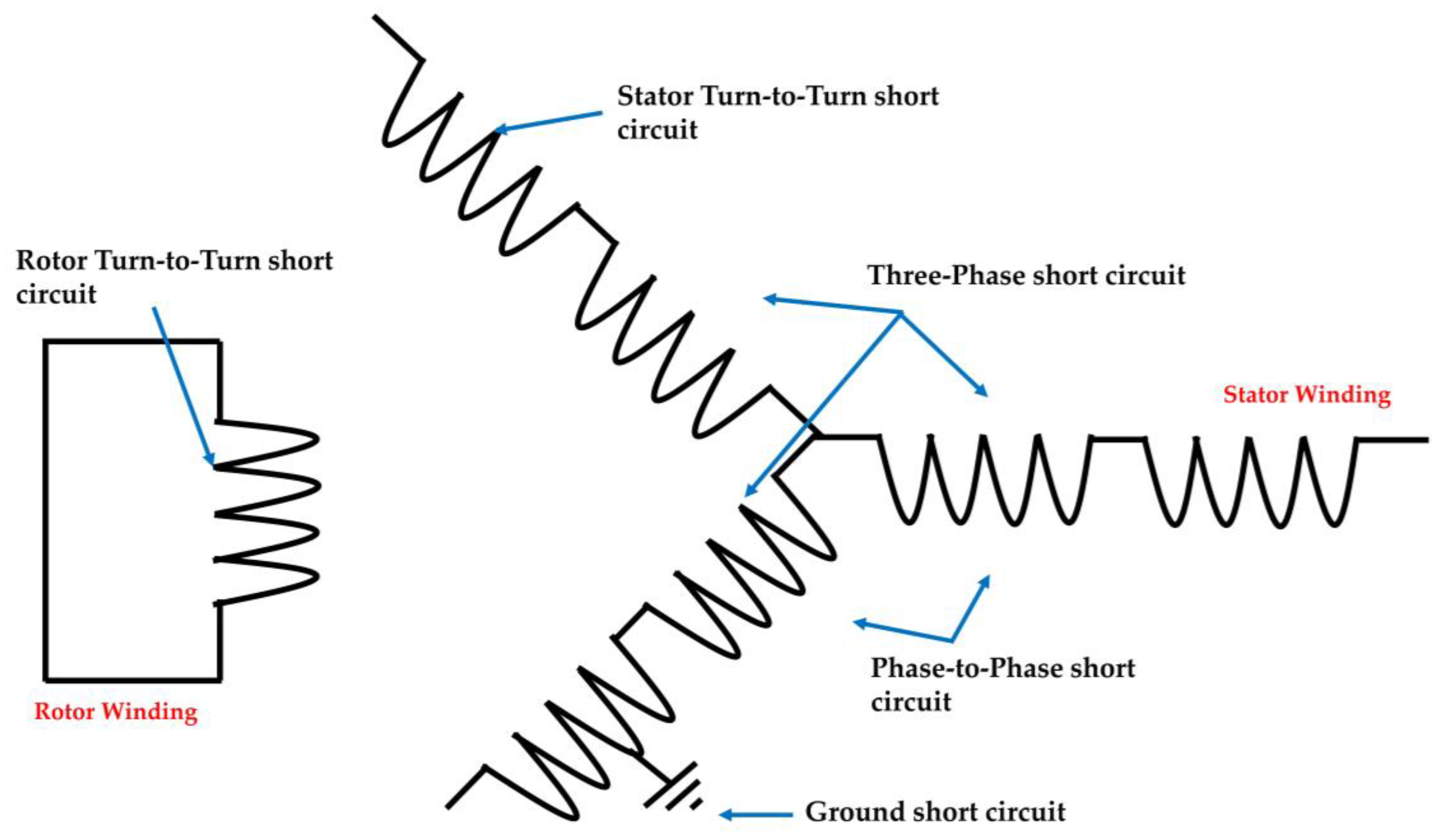
2. Electrical Fault Types in Synchronous Generators

2.1. Stator Winding Faults

Electrical faults in stator windings are crucial to the performance and reliability of synchronous generators. These faults can be categorized into several types, each affecting the generator differently. Figure 1 illustrates the various types of faults in the stator windings, specifically showing turn-to-turn short circuits, ground faults, and phase-to-phase short circuits within a three-phase coil system.

2.1.1. Ground Short Circuit

Ground short circuits in high-voltage synchronous generators usually occur due to insulation degradation over time. These faults produce low-amplitude fault currents that typically do not exceed a few amperes but can occasionally surge to up to 20 amperes, potentially damaging the stator iron [13]. The subtlety of these currents necessitates rapid detection and remediation to prevent more severe consequences. Advanced monitoring techniques, such as electromagnetic signature analysis, can be used to detect these faults early by identifying changes in the magnetic field and electrical signatures that deviate from the normal operational parameters.

2.1.2. Phase Short Circuit

Phase short circuits occur when the insulation fails, allowing for direct contact either between two phases or between a phase and the ground. This type of fault can trigger substantial current flows, posing the risk of significant damage to the generator. Quick intervention via protective systems is necessary. Techniques such as real-time impedance monitoring and analysis are crucial in rapidly and accurately identifying these faults.

2.1.3. Turn-to-Turn Faults in Stator Windings

Turn-to-turn faults occur when the insulation fails between adjacent turns within a single phase. These faults create asymmetrical magnetic fields, inducing unusual currents that can compromise the winding’s structural integrity [14]. Detection coil methods and changes in the leakage magnetic flux can be used to effectively identify and localize these faults, preventing further damage and operational inefficiency.

2.2. Rotor Winding Faults

While less common, rotor winding faults are equally significant and can be diagnosed using similar methods to those developed for stator windings. As with stator winding faults, turn-to-turn faults in rotor windings usually result from insulation breakdown between turns due to aging, mechanical stress, or excessive heat. These faults can subtly affect the generator’s performance, leading to efficiency losses and increased operational costs if undetected. Non-invasive methods such as analyzing the rotor current and voltage signatures help to detect these faults without requiring a shutdown, enhancing operational reliability and maintenance efficiency.
By integrating these advanced diagnostic techniques and focusing on their application in detecting specific fault types, this work offers a comprehensive overview of the common faults that occur in synchronous generators and presents modern solutions to these challenges. Despite extensive research on fault diagnosis for induction generators, studies on synchronous generators remain relatively scarce [5,15,16,17]. This study aims to fill this gap, enhancing the technical depth and relevance of research on the maintenance and operation of synchronous generators.

3. Electromagnetic Signal Analysis

The goal of fault diagnosis algorithms in electrical machinery is to provide reliable and efficient solutions using cost-effective equipment. These algorithms must also be capable of detecting the location and severity of short circuit faults within stator windings, which is essential in preventing severe damage and reducing machine downtime.

3.1. Non-Invasive Diagnostic Approaches

Traditional fault detection methods often involve invasive procedures that can be costly and time-consuming and potentially cause further damage to the equipment [8]. In contrast, non-invasive techniques offer a promising alternative, allowing for the faults to be detected without the need to dismantle the generator. Non-invasive methods, including the analysis of electromagnetic signals, are not only safer but also allow for continuous monitoring and immediate response, which is critical to minimizing downtime and optimizing maintenance schedules [18].
One of the advantages of non-invasive electromagnetic signal analysis is its ability to provide real-time data on the operational health of the generator. By analyzing changes in the stray magnetic flux and stator currents, these techniques can be used to pinpoint anomalies that indicate the presence of faults. The precision with which these signals can be interpreted often allows for the early detection of inter-turn short circuits, a crucial factor in mitigating the risk of catastrophic failure.

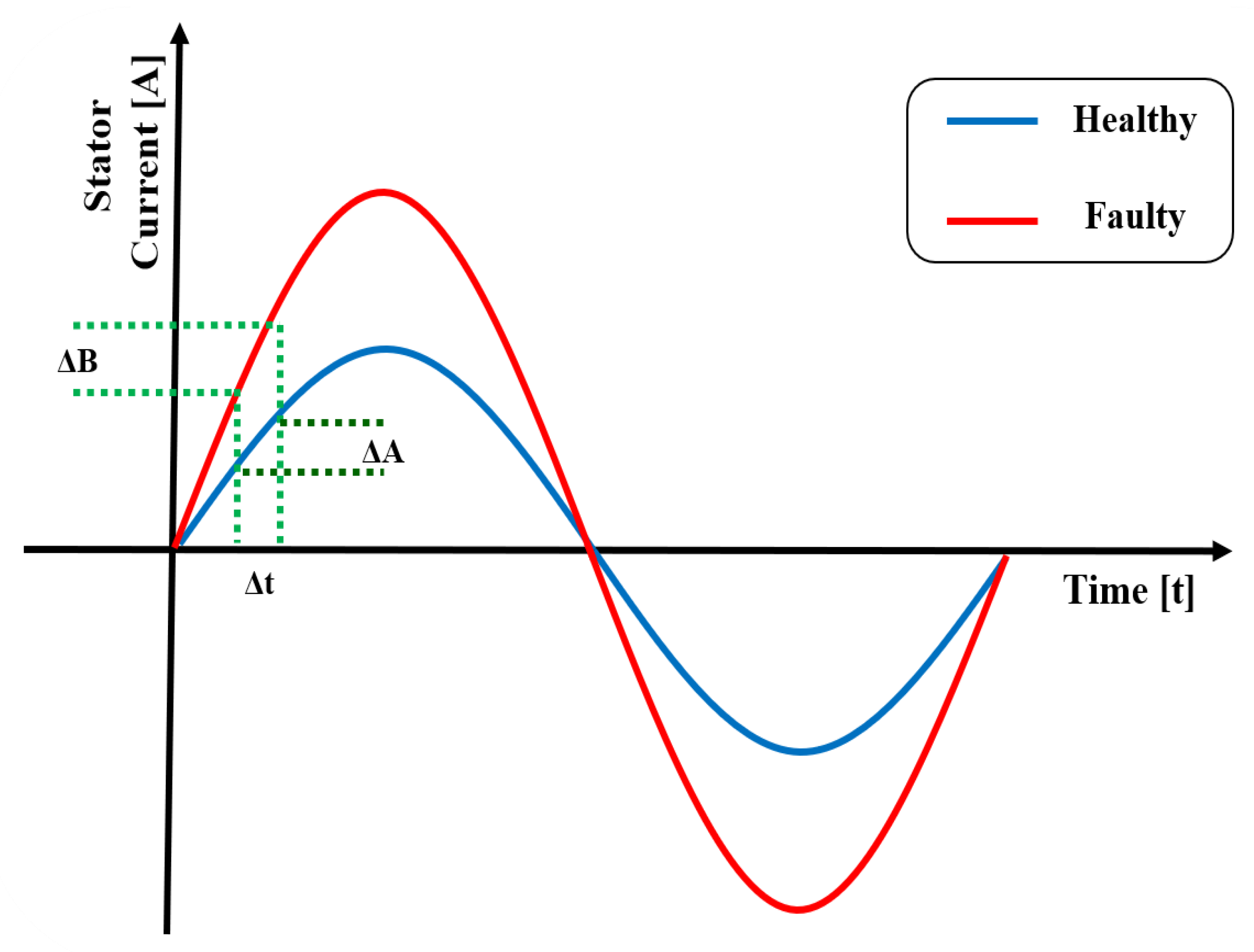
3.1.1. Stator Current Analysis

Stator current measurement is a pivotal diagnostic tool for the identification of faults within synchronous generators, leveraging the natural properties of stator windings. This method detects asymmetries in the magnetic field caused by short circuit faults, which directly impact the current waveform. These asymmetries are captured through the detailed analysis of the magnitude and phase variations in the stator current [19]. Additionally, Fast Fourier Transform (FFT) analysis is employed to identify specific frequencies that indicate various types of faults. This approach allows for a precise and quantitative evaluation of the fault conditions, facilitating the detection and analysis of anomalies under diverse operational conditions without the need for additional or intrusive equipment.
FFT analysis is crucial in transforming time-domain signals into their frequency components, thereby aiding in the diagnosis of electrical faults in synchronous generators. By decomposing the stator currents into frequency spectra, FFT analysis highlights abnormal frequencies that emerge from electrical faults. This method involves analyzing a curve representing the function f(x), expressed by the following equation:
f x = a 0 + n = 1 N ( a n cos n x + b n sin ( n ) )
In this equation, a0 represents the average or DC component of the function over one period, providing a baseline level for the stator current. an and bn are the Fourier coefficients for each harmonic n, with a quantifying the amplitude of the cosine components, and bn is the sine component of the harmonics. These coefficients are critical in identifying specific frequency components within the signal. T is the period of the fundamental frequency of the signal used to normalize the Fourier coefficient, and w0 is the fundamental angular frequency. n varies from 1 to N, where N is the highest harmonic considered in this analysis.

3.1.2. Stray Magnetic Field Analysis

Stray magnetic field analysis serves as another essential non-invasive diagnostic technique that is crucial in identifying turn-to-turn short circuits. Faults disrupt the uniform magnetic field distribution within the air gap, causing variations in the magnetic flux density [20]. These variations affect both the shape and intensity of the magnetic field around the stator windings and are measured to understand the nature of the fault and its impact on the generator’s performance. Despite the effectiveness of the air-gap magnetic field for detecting internal turn-to-turn short circuits, its invasive nature makes it difficult to implement in already operational synchronous generators. Additionally, search coils installed on the stator tooth are prone to failure due to their fragility. To address these challenges, stray magnetic field analysis has emerged as a non-invasive and reliable alternative [21]. To enhance the precision of this analysis, the stray magnetic field, primarily resulting from the leakage flux that follows the stator’s backside, is crucial. By establishing a zero-flux boundary condition at a slight distance from the stator core and employing sensitivity analysis, this method ensures the accurate capture and interpretation of stray flux patterns. This setup allows for continuous monitoring and immediate fault detection using sensors positioned strategically behind the stator’s back yoke without disrupting the generator’s operations.

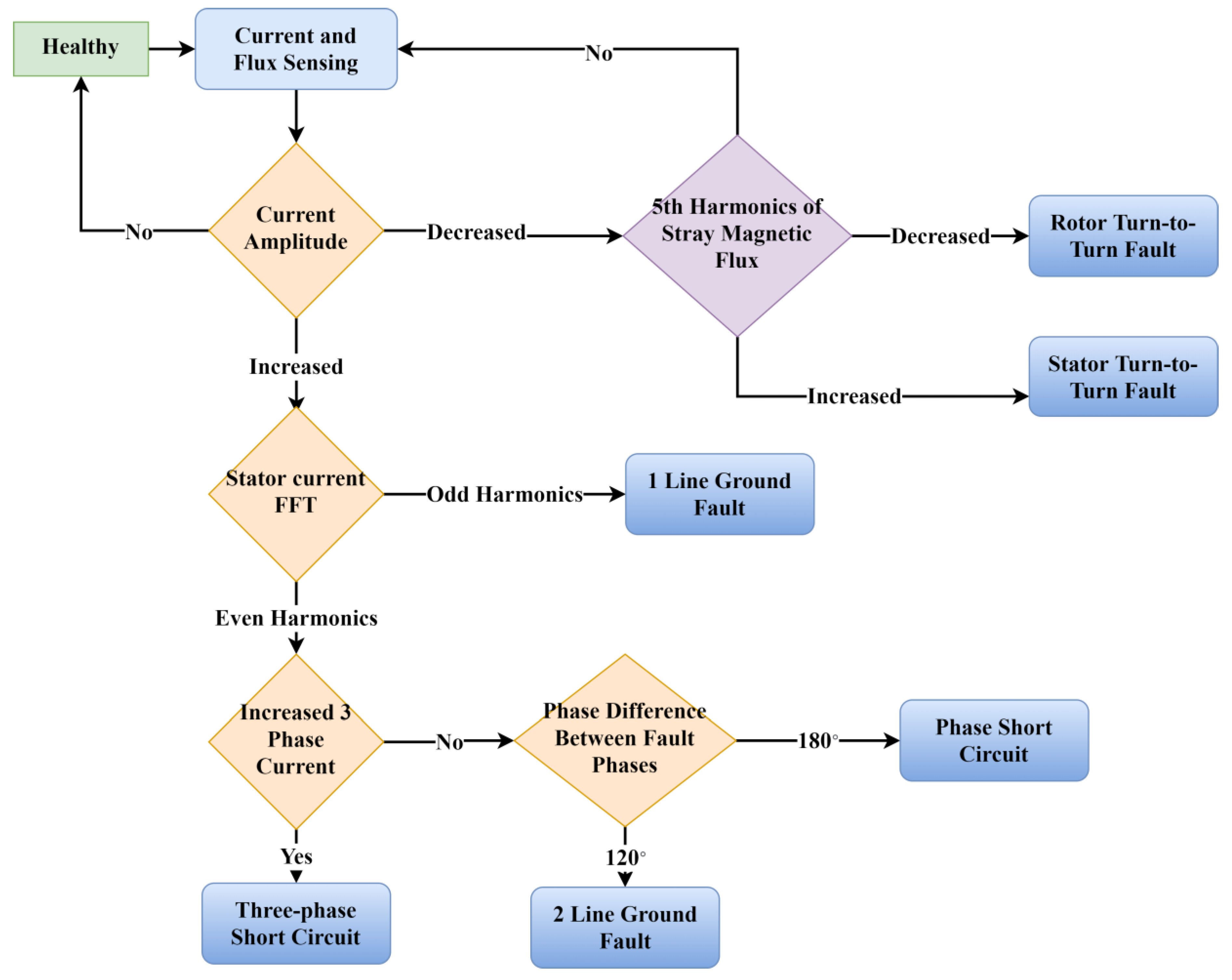
3.2. Fault Diagnosis Techniques in Synchronous Generators

3.2.1. Implementation of Fault Diagnosis Algorithm

Figure 2 shows a comprehensive fault diagnosis algorithm designed to identify various fault types in synchronous generators. The algorithm begins by measuring the current’s magnitude. An increase in current magnitude suggests severe faults, such as phase-to-phase or ground faults, while a decrease in current magnitude indicates possible turn-to-turn faults. Following this initial assessment, if the current magnitude has increased, FFT analysis is applied to identify the specific harmonic frequencies associated with the fault. Odd harmonics typically suggest ground faults, while even harmonics indicate phase-to-phase shorts. Additionally, phase difference analysis using Lissajous curves helps to distinguish between these faults by plotting two sinusoidal signals against each other. A phase shift of 120 degrees typically indicates a two-line ground fault, whereas a shift of 180 degrees suggests a phase-to-phase short circuit. If the initial assessment shows a decrease in current magnitude, it suggests a turn-to-turn fault. To differentiate between rotor turn-to-turn and stator turn-to-turn faults, an FFT analysis of the stray magnetic flux is conducted. An increase in the fifth harmonic indicates a stator turn-to-turn fault, while a decrease suggests a rotor turn-to-turn fault.
This diagnostic process is crucial in ensuring operational efficiency and preventing severe damage, with real-time execution allowing for continuous monitoring and immediate corrective actions if necessary.

3.2.2. Stator Current Amplitude Analysis

In synchronous generators, monitoring the stator current’s magnitude and its rate of change is critical in detecting faults. Current magnitude analysis is the first step in the algorithm to distinguish between turn-to-turn short circuits and other types of faults. The key parameters used in this analysis are ΔA, which measures the absolute difference in the current magnitude between two consecutive points, and ΔB, the time interval between these measurements, as illustrated in Figure 3. By calculating the ΔB/ΔA ratio, we can assess whether a significant current fluctuation indicates a fault. A ratio larger than a certain threshold K1 suggests a rapid increase in current, typically associated with phase-to-phase or ground faults, indicating more severe electrical issues. Conversely, a ratio smaller than another threshold K2 might indicate a decrease in current due to turn-to-turn faults, where the effectiveness of the winding is compromised.
These thresholds, K1 and K2, are set based on operational norms and are intended to provide suitable values to distinguish between normal operational fluctuations and those indicative of faults. This method allows for the early detection of abnormalities in the current behavior, enabling maintenance teams to quickly diagnose and rectify issues, thereby enhancing the reliability and safety of generator operations without the need for invasive procedures.

3.2.3. FFT Analysis for Stator Current and Stray Magnetic Flux

If the current magnitude increases, stator current FFT analysis is performed; if it decreases, stray magnetic FFT flux analysis is conducted. FFT analysis is a crucial method for the identification of specific frequencies that indicate various faults in synchronous generators. This technique converts time-domain signals into their frequency components, highlighting abnormal frequencies caused by electrical faults. By breaking down the current signal f(x) into its spectral components using the FFT, it allows for the pinpointing of specific frequencies related to different types of faults. Table 1 summarizes the frequency variations associated with each fault type in a synchronous generator.
While FFT analysis can be performed on all three phases of a synchronous generator, analyzing only one phase is often sufficient due to computational constraints. This is because the increase in the harmonic frequencies resulting from faults is typically consistent across all phases, whether they are directly affected by the fault or not. Current measurements are taken for all three phases, but focusing the FFT analysis on one phase minimizes computational load. This approach ensures that fault detection remains effective while optimizing the use of computational resources, making the diagnostic process both efficient and accurate.

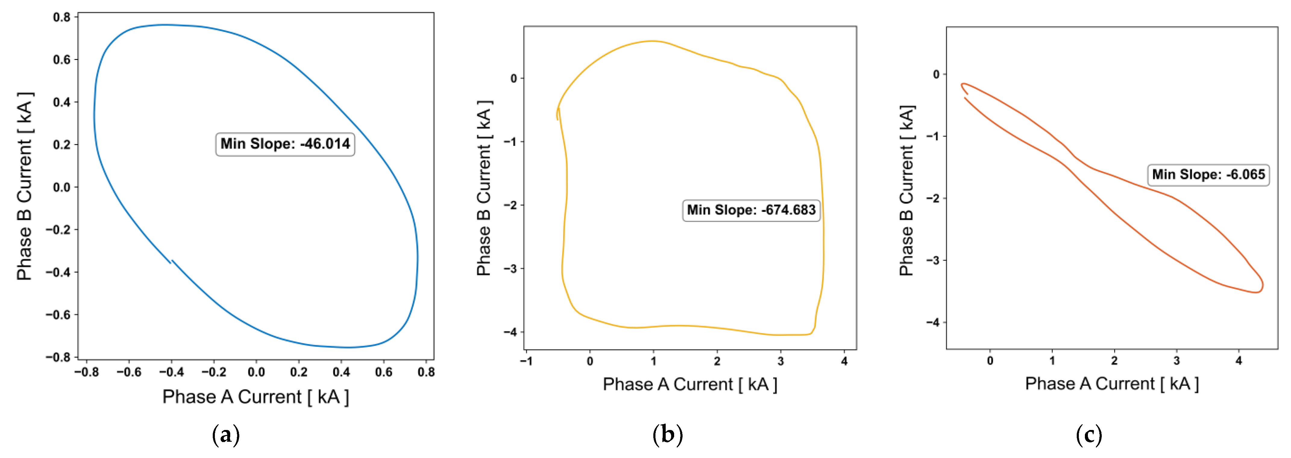
3.2.4. Phase Shift Analysis for Stator Currents

Phase difference analysis is used to further enhance the diagnostic accuracy, especially in distinguishing between similar fault signals, such as those of ground faults and phase-to-phase faults. Ground faults typically result in a phase difference of approximately 120 degrees between the fault and a healthy state. In contrast, phase-to-phase short circuits result in a phase difference of approximately 180 degrees. One effective method for the detection of phase differences is the use of Lissajous curves, whereby two sinusoidal signals are plotted against each other [22]. The parametric representation of these curves can be expressed as follows:
x t = A x sin w x t + y t = A y sin w x t + + δ
Removing the time variable t, the Lissajous curve equation is represented as follows:
y t = A y sin w y w x a r c s i n ( x A x ) + + δ
When the frequencies of the two signals are equalized, it simplifies as follows:
y t = A y sin arcsin x A x + δ
The phase difference and amplitude determine the shape of the Lissajous curve, which can indicate the presence and type of a fault. By analyzing the phase shift, different types of faults can be accurately distinguished, enhancing the precision of the diagnostic process. For example, as shown in Figure 4, a Lissajous curve with a 120° phase shift indicates a ground fault, while a curve with a 180° phase shift suggests a phase-to-phase short circuit.
In the proposed online monitoring system for synchronous generators, phase shift analysis is executed by continuously comparing the differences in the current measurements. This involves calculating the difference between consecutive current samples, where m represents the index of the current sample, and n is the number of sample offsets used for comparison, typically representing a fixed interval in the cycle. These differences are crucial in analyzing the resultant shape of the Lissajous curves and are defined by the following formula:
X = I m ,   Y = I ( m n )
Δ X = I m I m 1 , Δ Y = I m n I ( m n 1 )
In theory, this method should produce clear results under ideal conditions. However, actual analysis indicates that the harmonics interfere with the formation of perfect ellipses or straight lines in the Lissajous curves. Without harmonics, the slope of these curves would differentiate a phase difference of 120 degrees from 180 degrees, depending on whether the slope is less than −1 or not. Due to the presence of harmonics, it is necessary to adjust the threshold value to be significantly lower than −1, which allows for an effective fault diagnosis based on the observed curve shapes.

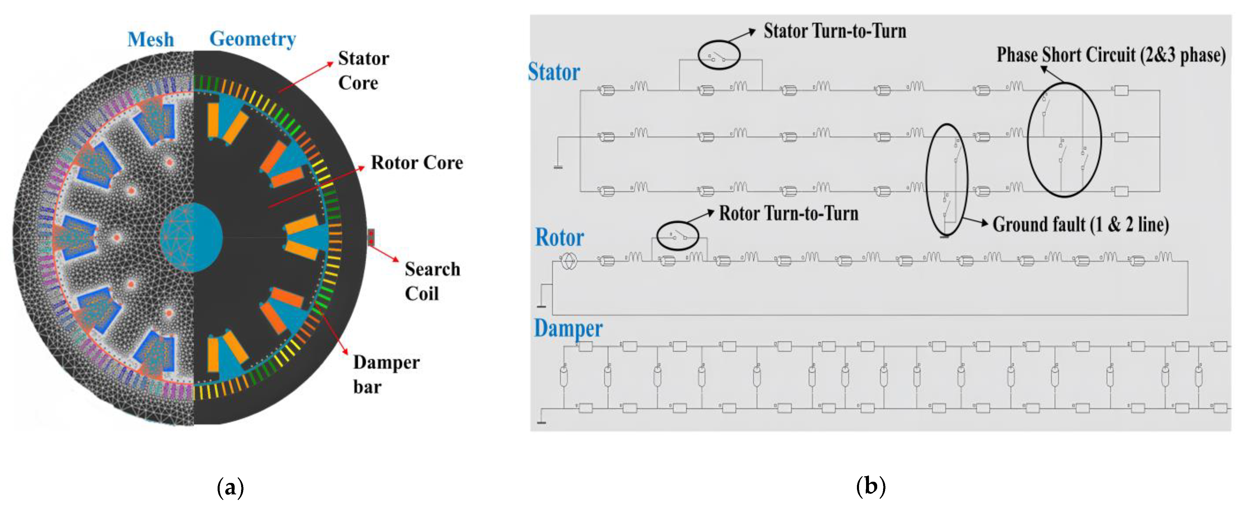
4. FEM Simulation Validation

4.1. Simulation Setup

The simulation of the synchronous generator was carried out using Altair’s Flux 2D software, version 2023.1, with the generator’s specific parameters detailed in Table 2.
Figure 5 represents the generator’s geometry and electrical circuit, highlighting the setup for the fault simulation experiments. The design incorporates strategically placed switches among the phase connections and the ground, allowing for the simulation of various fault scenarios, such as short circuits and ground faults. Additionally, switches within the coil setup are used to simulate turn-to-turn faults, with the ability to vary the severity so as to effectively model these conditions in the generator model.
The generator was operated to ensure accurate simulation results until it reached a steady state following the transient phase. At the 0.4-second mark, a sudden fault was introduced to test the system’s response under abrupt failure conditions. This setup allowed for a comprehensive analysis of the generator’s behavior under different fault scenarios, providing valuable insights into its fault tolerance and diagnostic capabilities.
The stator and rotor cores were composed of 0.5 mm laminations of low-loss steel (M270-50A steel), while the damper bars and windings were made of copper. The simulation involved a mesh of 179 lines and 13,811 nodes to accurately capture the generator’s physical and electrical characteristics. The boundary conditions were set to simulate a realistic operating environment, with a zero-flux boundary condition established at a slight distance from the stator core to capture the stray magnetic field accurately. Sensitivity analysis was employed to ensure the precision of stray flux patterns.

4.2. Simulation Results

4.2.1. Ground Short Circuit

The simulation of ground faults in synchronous generators reveals significant changes in the generator’s electrical characteristics. For a single-line ground fault, the FFT analysis showed an increase in odd harmonics, such as the third, fifth, and seventh orders. This fault caused a significant rise in current in the faulted phase, making it easier to pinpoint the fault location. Figure 6 illustrates these findings, presenting both the FFT results and the stator current waveforms for a single-line ground fault scenario.
In the two-line ground fault scenario, the current in the faulted phases notably increased, with a phase difference of approximately 120 degrees between them. The FFT results for this fault type showed an elevation in even harmonics, including the second and fourth orders. Figure 7 clearly outlines the impact of the fault on the generator’s electrical behavior, showing both the stator current waveforms and the corresponding FFT data.

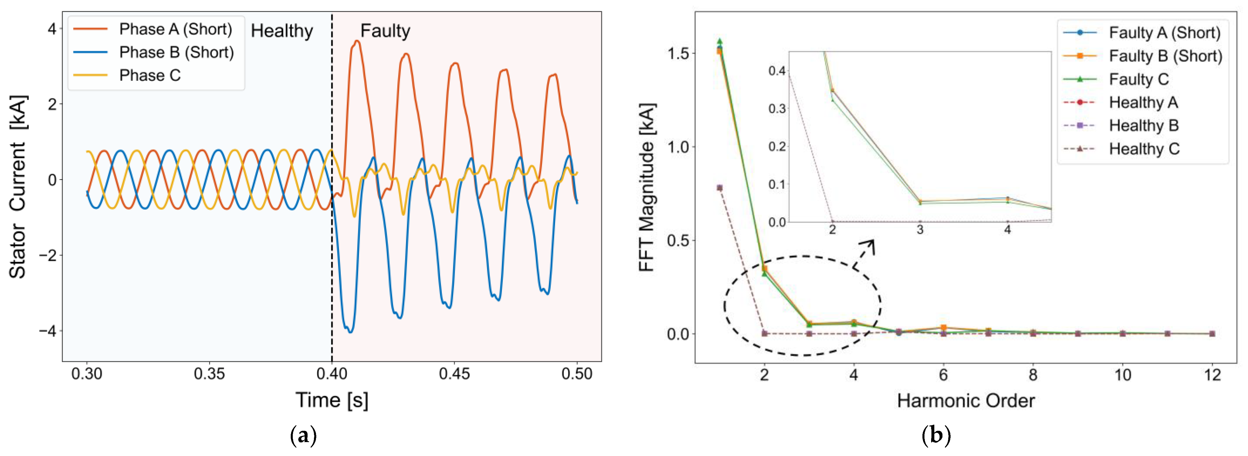
4.2.2. Phase Short Circuit

For phase-to-phase short circuits, the fault currents in the affected phases were significantly higher compared to a healthy system. The observed 180-degree phase shift in the fault currents was due to the currents in the affected phases flowing in opposite directions. While there was a slight increase in odd harmonics, the analysis highlighted a more significant rise in even harmonics, such as the second and fourth orders, which surpassed the subsequent odd harmonics (see Figure 8).
This type of fault causes an increase in the current magnitudes of the affected phases and a rise in even harmonics, creating a pattern similar to that of two-line ground faults. Due to these similarities, the accurate identification of the fault requires distinguishing between the different phase differences. This can be effectively achieved by analyzing the Lissajous curves. Figure 9 shows the Lissajous curves for the healthy condition, a two-line ground fault, and a phase-to-phase short circuit. The minimum slopes of each Lissajous curve are −46.013 for the healthy condition, −674.683 for the two-line ground fault, and −6.065 for the phase-to-phase short circuit.
A similar pattern is observed in three-phase short circuits, where the fault phases exhibit elevated currents. The FFT analysis confirms the increase in even harmonics, supporting the use of even harmonics for fault identification in three-phase scenarios, as shown in Figure 10.

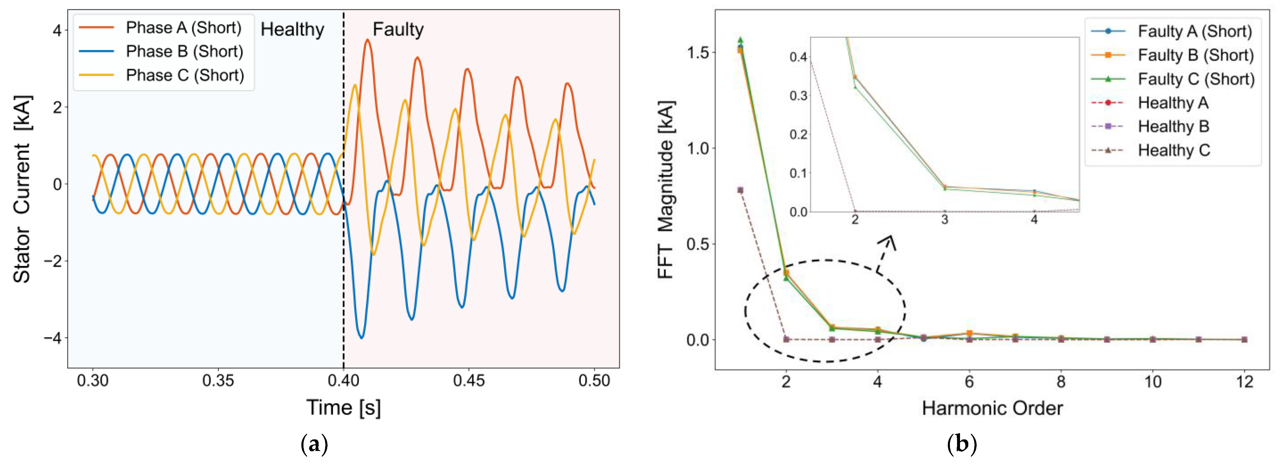
4.2.3. Stator Turn-to-Turn Short Circuit

In the simulation results depicted in Figure 11, the current induced in the affected stator coil shows a reduction of 11.4% due to the decreased number of turns caused by the fault. This reduction is proportional to the severity of the fault: a 20% fault results in a 22.1% decrease in current, and a 30% fault causes a 32.8% decrease. However, no significant changes were observed in the FFT analysis. The decline in the stator current magnitude could indicate temporary reductions due to protective function activations or insulation deterioration, complicating the diagnosis of a stator turn-to-turn fault based solely on this parameter. Therefore, analyzing the stray magnetic flux becomes crucial. The stray flux analysis shows an increase, particularly in the fifth harmonic, which aligns with the number of pole pairs.

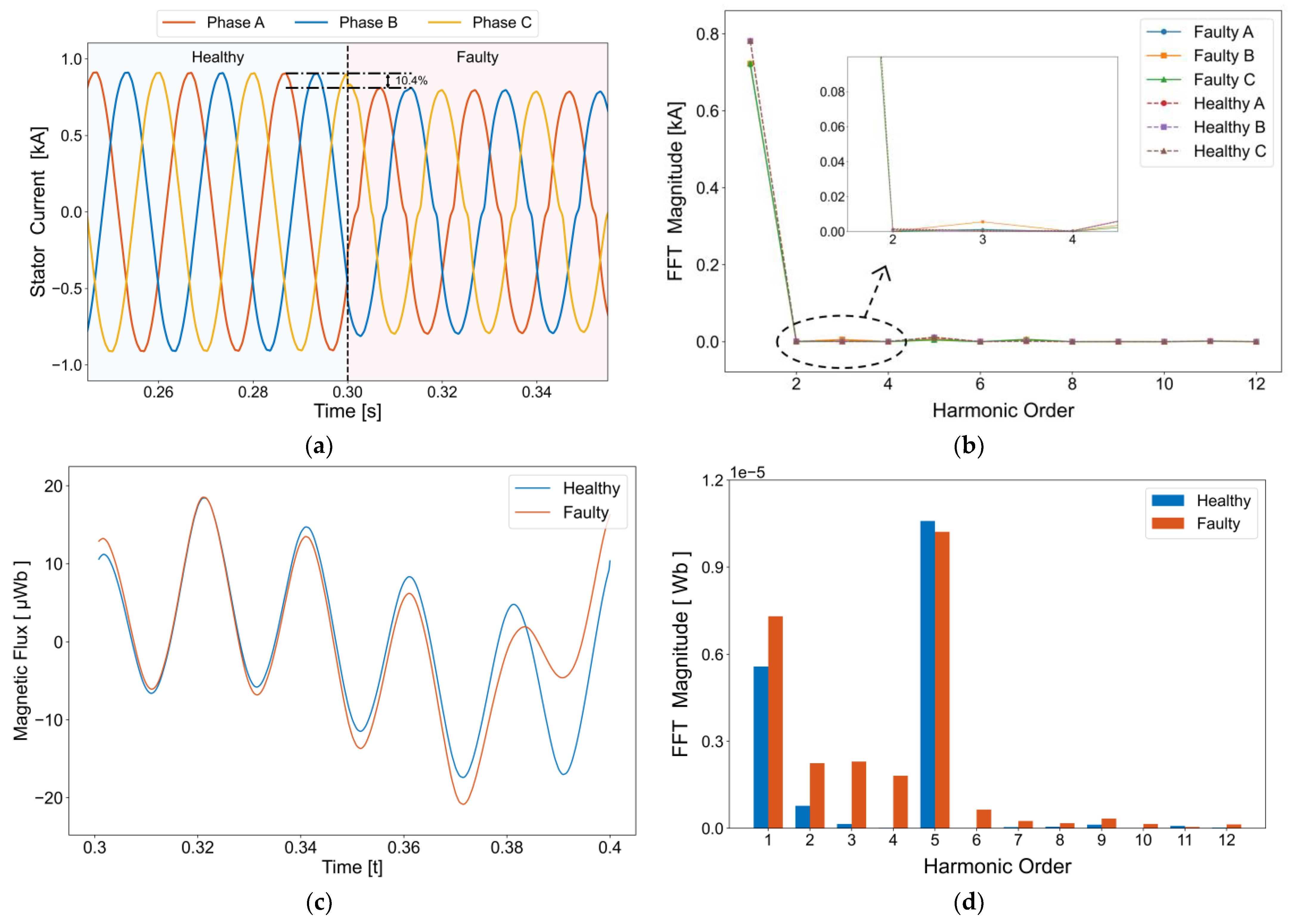
4.2.4. Rotor Turn-to-Turn Short Circuit

In the simulation of rotor turn-to-turn faults, as shown in Figure 12, a 10% severity fault condition was set, reducing the induced magnetic flux due to fewer turns in the rotor coils. This resulted in a 10.4% reduction in the stator currents across all phases, with no significant changes noted in the FFT analysis. For a 20% fault, the current decreased by 20.5%; for a 30% fault, the current decreased by 30.8%. However, distortions were observed in the stray magnetic flux analysis as the faulted rotor poles neared the sensors, indicating variations across different harmonic orders—notably a decrease in the previously dominant fifth harmonic. This detailed examination of the stator currents and stray magnetic flux enables precise fault diagnosis, demonstrating the value of magnetic flux measurements in identifying rotor-related issues in synchronous generators.

5. Conclusions

This study has effectively shown how the integration of electromagnetic signal analysis with traditional diagnostic methods can significantly improve fault detection in synchronous generators. By using FEM to simulate various fault scenarios, this research highlights the crucial role of magnetic flux measurements in both detecting the presence of faults and identifying their specific types within generator systems.
The use of non-invasive diagnostic techniques, which combine stator current and stray magnetic flux FFT analysis, minimizes the operational disruptions typically associated with fault detection. At the same time, it enhances the capacity for real-time monitoring and rapid response. This shift toward predictive maintenance strategies is poised to transform the maintenance protocols for synchronous generators, thereby boosting the reliability and efficiency of power systems worldwide.
However, these conclusions are drawn from simulation data, and there are limitations related to the diverse operating conditions of the generators and noise handling. Further experimental validation is required to address these limitations. Future research will aim to expand these diagnostic techniques to include mechanical fault diagnostics using the same sensor technologies. Additionally, integrating machine learning algorithms will further automate and improve fault detection and diagnosis processes. These advancements are expected to revolutionize maintenance strategies for synchronous generators, leading to more sustainable and cost-effective power generation.

Author Contributions

Design and application—the literature review and manuscript preparation, as well as the simulations—were carried out by J.P. The final review of the manuscript and corrections were completed by P.N.H., H.M., and J.B. All authors have read and agreed to the published version of the manuscript.

Funding

This research was funded by the Education and Research Promotion Program of KOREATECH in 2024 and supported by a research grant from Hyundai Motor Group (202400500001).

Data Availability Statement

No new data were created or analyzed in this study. Data sharing is not applicable to this article.

Conflicts of Interest

The authors declare no conflicts of interest.

References

  1. Karatuğ, Ç.; Arslanoğlu, Y. Development of Condition-Based Maintenance Strategy for Fault Diagnosis for Ship Engine Systems. Ocean Eng. 2022, 256, 111515. [Google Scholar] [CrossRef]
  2. Salomon, C.P.; Ferreira, C.; Sant’Ana, W.C.; Lambert-Torres, G.; Borges Da Silva, L.E.; Bonaldi, E.L.; De Oliveira, L.E.D.L.; Torres, B.S. A Study of Fault Diagnosis Based on Electrical Signature Analysis for Synchronous Generators Predictive Maintenance in Bulk Electric Systems. Energies 2019, 12, 1506. [Google Scholar] [CrossRef]
  3. Verginadis, D.; Antonino-Daviu, J.A.; Karlis, A.; Danikas, M.G. Determination of the Insulation Condition in Synchronous Generators: Industrial Methods and A Case Study. IEEE Ind. Appl. Mag. 2022, 28, 67–77. [Google Scholar] [CrossRef]
  4. Lee, S.B.; Tallam, R.M.; Habetler, T.G. A Robust, on-Line Turn-Fault Detection Technique for Induction Machines Based on Monitoring the Sequence Component Impedance Matrix. IEEE Trans. Power Electron. 2003, 18, 865–872. [Google Scholar] [CrossRef]
  5. Nandi, S. Detection of Stator Faults in Induction Machines Using Residual Saturation Harmonics. In Proceedings of the IEEE International Conference on Electric Machines and Drives, San Antonio, TX, USA, 15 May 2005; IEEE: San Antonio, TX, USA, 2005; pp. 256–263. [Google Scholar]
  6. Jie, H.; See, K.Y.; Chang, Y.; Gao, R.X.-K.; Fan, F.; Zhao, Z. Enhancing Motor Impedance Measurements: Broadening the Spectrum from Low to High Frequencies. Meas. Sci. Technol. 2024, 35, 086008. [Google Scholar] [CrossRef]
  7. Fan, F.; Zhao, Z.; Jie, H.; Sun, Q.; Tu, P.; Shu, Z.; Wang, W.; See, K.Y. Impact of Motor Stator Winding Faults on Motor Differential-Mode Impedance and Mode Transformation. Chin. J. Electr. Eng. 2022, 8, 12–21. [Google Scholar] [CrossRef]
  8. Tavner, P.J. Review of Condition Monitoring of Rotating Electrical Machines. IET Electr. Power Appl. 2008, 2, 215–247. [Google Scholar] [CrossRef]
  9. Sdid, M.S.N.; Benbouzid, M.E.H. H-G Diagram Based Rotor Parameters Identification for Induction Motors Thermal Monitoring. IEEE Trans. Energy Convers. 2000, 15, 14–18. [Google Scholar] [CrossRef]
  10. Sadeghi, I.; Ehya, H.; Faiz, J.; Ostovar, H. Online Fault Diagnosis of Large Electrical Machines Using Vibration Signal-a Review. In Proceedings of the 2017 International Conference on Optimization of Electrical and Electronic Equipment (OPTIM) & 2017 Intl Aegean Conference on Electrical Machines and Power Electronics (ACEMP), Brasov, Romania, 25–27 May 2017; IEEE: Brasov, Romania, 2017; pp. 470–475. [Google Scholar]
  11. Wang, T.; Han, Q.; Chu, F.; Feng, Z. Vibration Based Condition Monitoring and Fault Diagnosis of Wind Turbine Planetary Gearbox: A Review. Mech. Syst. Signal Process. 2019, 126, 662–685. [Google Scholar] [CrossRef]
  12. Osornio-Rios, R.A.; Zamudio-Ramírez, I.; Jaen-Cuellar, A.Y.; Antonino-Daviu, J.; Dunai, L. Data Fusion System for Electric Motors Condition Monitoring: An Innovative Solution. IEEE Ind. Electron. Mag. 2023, 17, 4–16. [Google Scholar] [CrossRef]
  13. Sadeghi, I.; Ehya, H.; Faiz, J.; Akmal, A.A.S. Online Condition Monitoring of Large Synchronous Generator under Short Circuit Fault—A Review. In Proceedings of the 2018 IEEE International Conference on Industrial Technology (ICIT), Lyon, France, 20–22 February 2018; IEEE: Lyon, France, 2018; pp. 1843–1848. [Google Scholar]
  14. Neti, P.; Nandi, S. Stator Interturn Fault Detection of Synchronous Machines Using Field Current and Rotor Search-Coil Voltage Signature Analysis. IEEE Trans. Ind. Appl. 2009, 45, 911–920. [Google Scholar] [CrossRef]
  15. Mirafzal, B.; Povinelli, R.J.; Demerdash, N.A.O. Interturn Fault Diagnosis in Induction Motors Using the Pendulous Oscillation Phenomenon. IEEE Trans. Energy Convers. 2006, 21, 871–882. [Google Scholar] [CrossRef]
  16. Tallam, R.M.; Lee, S.B.; Stone, G.C.; Kliman, G.B.; Yoo, J.; Habetler, T.G.; Harley, R.G. A Survey of Methods for Detection of Stator-Related Faults in Induction Machines. IEEE Trans. Ind. Appl. 2007, 43, 920–933. [Google Scholar] [CrossRef]
  17. Burriel-Valencia, J.; Puche-Panadero, R.; Martinez-Roman, J.; Sapena-Bano, A.; Pineda-Sanchez, M.; Perez-Cruz, J.; Riera-Guasp, M. Automatic Fault Diagnostic System for Induction Motors under Transient Regime Optimized with Expert Systems. Electronics 2018, 8, 6. [Google Scholar] [CrossRef]
  18. Kliman, G.B.; Premerlani, W.J.; Koegl, R.A.; Hoeweler, D. A New Approach to On-Line Turn Fault Detection in AC Motors. In Proceedings of the IAS ’96. Conference Record of the 1996 IEEE Industry Applications Conference Thirty-First IAS Annual Meeting, San Diego, CA, USA, 6–10 October 1996; IEEE: San Diego, CA, USA, 1996; Volume 1, pp. 687–693. [Google Scholar]
  19. Ma, H.; Li, H.; Wei, S.; Ju, P.; Zhang, L. Transient Analysis of Synchronous Generator with Stator Winding Faults Based on Starting Process. In Proceedings of the 2008 Third International Conference on Electric Utility Deregulation and Restructuring and Power Technologies, Nanjing, China, 6–9 April 2008; IEEE: Nanjing, China, 2008; pp. 1927–1932. [Google Scholar]
  20. Madonna, V.; Walker, A.; Giangrande, P.; Serra, G.; Gerada, C.; Galea, M. Improved Thermal Management and Analysis for Stator End-Windings of Electrical Machines. IEEE Trans. Ind. Electron. 2019, 66, 5057–5069. [Google Scholar] [CrossRef]
  21. Ehya, H.; Nysveen, A. Pattern Recognition of Interturn Short Circuit Fault in a Synchronous Generator Using Magnetic Flux. IEEE Trans. Ind. Appl. 2021, 57, 3573–3581. [Google Scholar] [CrossRef]
  22. Ehya, H.; Faiz, J. Electromagnetic Signature Analysis of Electrical Faults, 1st ed.; Wiley: New York, NY, USA, 2022; ISBN 978-1-119-63607-6. [Google Scholar]
Figure 1. Schematic Representation of Winding Faults.
Electronics 13 03078 g001
Figure 2. Diagnostic Flowchart for Electrical Faults in Synchronous Generators.
Electronics 13 03078 g002
Figure 3. Comparative Analysis of Stator Current in Healthy and Faulty Conditions.
Electronics 13 03078 g003
Figure 4. Lissajous Curves for Phase Shift Analysis: (a) Ellipse for 120° Phase Shift; (b) Line for 180° Phase Shift.
Electronics 13 03078 g004
Figure 5. Schematic representation of the synchronous generator used in the simulation: (a) cross-sectional geometry and mesh of the generator showcasing the arrangement of components; (b) detailed electrical circuit layout used for simulating various fault conditions.
Electronics 13 03078 g005
Figure 6. Simulation Results of a 1-Line Ground Fault: (a) Stator currents of three-phase; (b) FFT Analysis of Stator Currents.
Electronics 13 03078 g006
Figure 7. Simulation Results of a 2-Line Ground Fault: (a) Stator currents of three-phase; (b) FFT Analysis of Stator Currents.
Electronics 13 03078 g007
Figure 8. Simulation Results of a Phase Short Circuit: (a) Stator currents of three-phase; (b) FFT Analysis of Stator Currents.
Electronics 13 03078 g008
Figure 9. Results of Lissajous Curves for Fault Currents: (a) Lissajous Curves of Healthy Condition; (b) Lissajous Curves of 2-Line Ground Fault; (c) Lissajous Curves of Phase Short Circuit.
Electronics 13 03078 g009
Figure 10. Simulation Results of a Three-Phase Short Circuit: (a) Stator currents of three-phase; (b) FFT Analysis of Stator Currents.
Electronics 13 03078 g010
Figure 11. Simulation Results of a Stator Turn-to-Turn fault: (a) Stator currents of three-phase; (b) FFT Analysis of Stator Currents; (c) Magnetic Flux of Stator; (d) FFT Analysis of Stator Magnetic Flux.
Electronics 13 03078 g011
Figure 12. Simulation Results of a Rotor Turn-to-Turn fault: (a) Stator currents of three-phase; (b) FFT Analysis of Stator Currents; (c) Magnetic Flux of Stator; (d) FFT Analysis of Stator Magnetic Flux.
Electronics 13 03078 g012
Table 1. Frequency Variation Patterns of Fault Types in Synchronous Generators.
Fault TypeFrequency Variation PatternNotes
Stator Single-Line Ground Fault f g r o u n d = k o d d · f s Odd harmonics
f s is power supply frequency
Stator Two-Line Ground Fault f g r o u n d = k e v e n · f s Even harmonics
Phase-to-Phase Short Circuit f p h a s e = k e v e n · f s -
Three-Phase Short Circuit f 3 p h a s e = k e v e n · f s -
Stator Turn-to-Turn Short Circuit f s t a t o r _ t u r n = k o d d · f s + m · f r f r is rotation frequency
m is number of pole pairs
Rotor Turn-to-Turn Short Circuit f r o t o r _ t u r n = k o d d · f s m · f r -
Table 2. Parameter of Synchronous generator.
ParameterValueParameterValue
Rated Power (kVA)6400Radial Air-gap Length (mm)20
Pole Pairs5Stator outer diameter (mm)2700
Stator Slots120Stator inner diameter (mm)2120
Rated Voltage (V)4600Rotor core outer diameter (mm)2080
Load (Ohms)7Rotor core inner diameter (mm)500
Rated Rotor Current (A)230Stack length (mm)800
Disclaimer/Publisher’s Note: The statements, opinions and data contained in all publications are solely those of the individual author(s) and contributor(s) and not of MDPI and/or the editor(s). MDPI and/or the editor(s) disclaim responsibility for any injury to people or property resulting from any ideas, methods, instructions or products referred to in the content.

