Abstract
A pyroelectric temperature sensor for measuring human body temperature with increased accuracy and speed for application in mobile robotic systems has been developed. This pyroelectric temperature sensor for measuring human body temperature is intended for use in various educational institutions. Its usage will allow for identifying sick or potentially ill people and providing them with preliminary advice and avoid infecting other people. This is particularly important considering the seasonality of dangerous infectious diseases and the emergence of new ones (e.g., COVID-19). It is also advisable to use this pyroelectric sensor in hospitals, where temperature measurement is very crucial for monitoring the course of various diseases. The proposed pyroelectric temperature sensor is based on a nonlinear oscillatory system, which provides high sensitivity and allows for solving the problem of increasing the accuracy of measuring the human body temperature in a non-contact way. Measurement error is ±0.1% in the operating range (32–43) °C, measurement time—1 s, and the frequency instability is 3·10−4.
1. Introduction
1.1. Background
Human health is a priceless treasure. This is the most important of man’s needs. It is health that largely determines a person’s capabilities. In turn, maintaining health at the proper level is a rather complicated and complex task. Let us consider one of the important components of this task—monitoring humans’ body temperatures in educational institutions, shopping centers, train stations, airports, entertainment centers, and other busy places in order to identify potentially sick people in a timely manner. This is especially important nowadays when there are many different (including deadly) infectious diseases, as well as new, quite dangerous illnesses, such as various strains of COVID-19 and others. Sufficiently detailed information on COVID-19 is provided, for example, on the websites of the World Health Organization (WHO) and the European Centre for Disease Prevention and Control (ECDC) [1,2]. So, the main task here is to reduce the spread of diseases as much as possible and start treatment of the sick as soon as possible. Temperature measurement, of course, is extremely relevant for hospitals, where monitoring patients’ temperatures allows for timely and accurate determination and adjustment of the treatment process.
So, what is most often used to measure the temperature of the human body today? Quite often, such a meter is a conventional mercury thermometer. Despite its high accuracy and low price, it has significant drawbacks. These are the high toxicity of mercury, poor reliability of the glass case, and a rather long (up to 10 min) temperature measurement time. The latter drawback becomes especially noticeable when measuring the temperature of infants, or, for example, when measuring the temperature of a large number of people at different times. The complete hygiene and practical instantaneousness (2–7 s) of the non-contact method of measuring body temperature have long made non-contact thermometers one of the most promising tools [3,4]. Despite the development of technologies and the market for non-contact infrared thermometers, they are merely promising at this stage, and forecasts for mercury thermometer replacement in medical use remain mostly at the level of discussion. The main problems of non-contact thermometers still remain unresolved. These include the rather low measurement accuracy (error can reach ±0.50 °C) and very high price (twice as expensive as mercury thermometers) [5].
A previous analysis of the most common modern means of temperature measurement [6] showed the presence of drawbacks. One of these disadvantages is their structure complexity. The presence of a large number of components, with the modern principle of the miniaturization of technologies, is unacceptable. In addition, the considered meters contain too many conversion circuits. This leads to additional errors, as well as an increase in conversion time. Another drawback is the low sensitivity of the devices. These problems of existing temperature-measuring devices can be overcome by using microelectronic frequency temperature converters based on transistor structures with negative resistance [7].
Studies on the temperature dependence of the impedance of semiconductor devices with negative resistance have shown promising results in terms of the possibility of building a self-oscillator primary measuring transducer on this basis [5,6].
The characteristics of existing non-contact infrared thermometers can be improved by using self-oscillatory systems based on the reactive properties of elements with negative resistance. Such systems have a number of advantages, namely, high interference immunity (providing high measurement accuracy), powerful output signal (which allows one to abandon precision amplifiers), and design simplicity (which increases the efficiency of devices built on their basis).
To study the properties of a temperature-sensitive measuring transducer, its mathematical model has to be developed. On the basis of this model, it is possible to obtain the dependence of the volt-ampere characteristic, the active and reactive components of the total resistance of the structure, and the generation frequency of the temperature and the power supply modes, as well as perform experimental studies and install it on a mobile robotic platform.
1.2. Problem Statement
The advent of mobile robotic systems for non-contact measurement of the human body’s temperature has been a significant technological advancement, particularly in the context of public health and safety. These systems are designed to autonomously navigate various environments such as hospitals, airports, and public spaces to perform temperature screenings without direct human intervention. However, despite their potential, current robotic systems face several limitations that hinder their effectiveness and widespread adoption.
The limitations of current robotic systems lay in four main categories: measurement accuracy and reliability, environmental interference, dynamic and static errors, and human–robot interaction. This research paper does not aim to consider all the limitations of modern robotic systems for the non-contact measurement of human body temperature but rather focuses on main one that introduces the largest error and to which a solution is proposed. The accuracy and reliability of human body temperature measurements are directly related to the measuring sensors. Modern temperature measurement sensors such as infrared thermometers and thermal imagers are prone to inaccuracies due to environmental factors such as ambient temperature, humidity, and airflow. These factors can lead to significant measurement errors, which calls into question the reliability of temperature readings [8,9].
Given these limitations, there is a pressing need for the development of an advanced mobile robotic system that can overcome the challenges associated with non-contact temperature measurement. A new solution should focus on the following aspects: the development of more accurate and reliable temperature sensors that can operate effectively under varying environmental conditions and the design of robots that are socially acceptable and user-friendly, with interfaces that provide clear and actionable feedback to operators and the public.
By addressing these limitations, the next generation of mobile robotic systems can provide a more accurate, reliable, and socially acceptable solution for the non-contact measurement of human body temperature, thereby enhancing public health monitoring and safety.
1.3. Objective
The aim of this work is to develop a pyroelectric temperature measurement sensor for application in a mobile robotic system with a human-centric design to measure the human body temperature with increased accuracy and reliability.
The object of this research is the process of converting radiation temperature into an analog output signal with a frequency information parameter.
The subject of this research is a non-contact pyroelectric thermometer for application in a mobile robotic system.
To achieve the goal of the work, we propose solving the following tasks:
- (1)
- To analyze modern non-contact pyroelectric thermometers to measure the human body temperature and justify the advantages of a thermometer based on a lambda-type self-oscillatory system in comparison with others.
- (2)
- To develop a mathematical model of a lambda-type self-oscillatory system with a pyroelectric sensing element in the time domain, which will help to obtain the dependence of voltages and currents in time, the dependence of the generation frequency, and the sensitivity of the device regarding temperature.
- (3)
- To develop a mobile robotic system with an electronic non-contact pyroelectric thermometer with increased accuracy and reliability.
1.4. Main Contribution
The main contributions of this paper are as follows:
- (1)
- The authors developed a pyroelectric sensor with a self-oscillator transducer for the non-contact measurement of the human body temperature, which has high accuracy, precision, and measuring speed.
- (2)
- The authors developed a mathematical model of the proposed pyroelectric sensor with a self-oscillator transducer for the non-contact measurement of the human body’s temperature.
- (3)
- The authors made an experimental model of the device for use in mobile robotic systems and obtained new results from experimental studies that confirmed the correctness/adequacy of the proposed mathematical model.
2. Materials and Methods
2.1. Non-Contact Measurement Technology
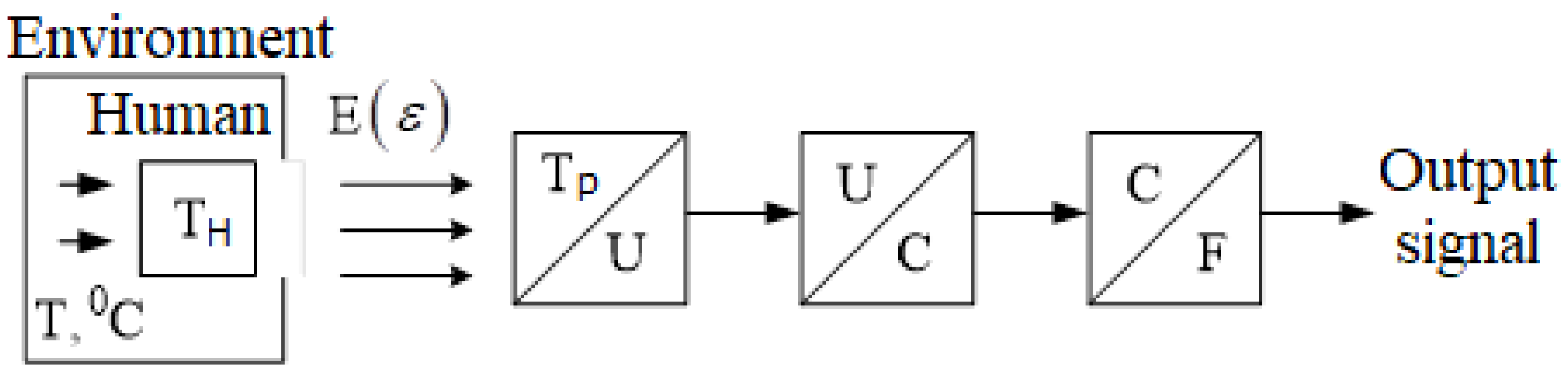
Human body temperature is measured in a non-contact way by a primary pyrometric transducer (PPT). Thermal radiation falls on the sensing element of the PPT and is then transmitted to the control element [10]. As a rule, the control element is a pyroelectric, on which a thermosensitive film of black metal is applied. The third component of the FET is the actuating element—this is usually a transistor or operational amplifier [11]. We propose combining thin pyroelectric films with circuits of transistor structures with negative resistance. Figure 1 shows a block diagram of the measuring transformation of the temperature of non-crystalline semiconductors into a change in the output signal frequency.
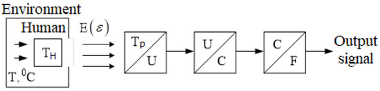
Figure 1.
Block diagram of the measuring transformation.
Notation: T is the heating temperature of the furnace; TH is the temperature of the human body; E is the flux of thermal radiation of the human body caused by its heating; ε is the integral emissivity of the human body; and Tp is the temperature of the sensitive pyroelectric element caused by the impact of the thermal radiation flux on it. Thus, the actual value of the human body temperature is Th = Tp/ε1/4.
2.2. Mathematical Model of the Temperature Measurement Sensor
First, we developed a mathematical model of the temperature measurement sensor to find the analytical and graphical representation of the transformation function F(T).
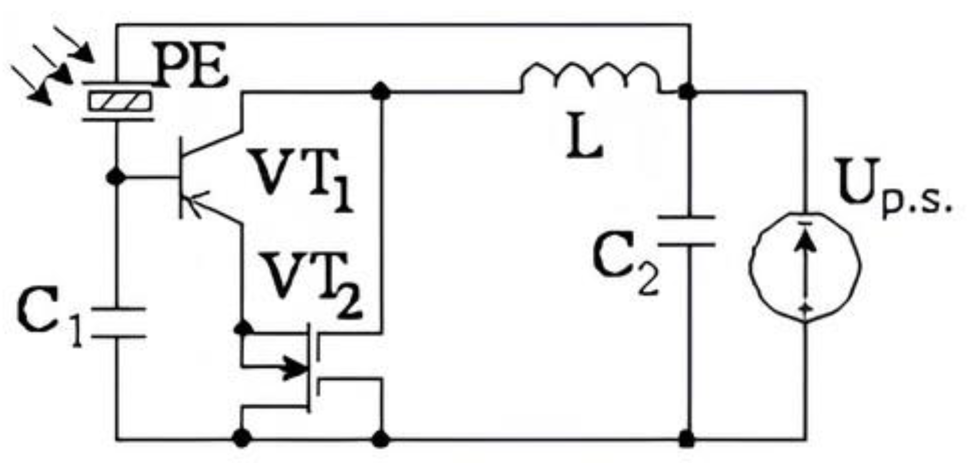
Mathematical modeling of the measuring sensor of human body temperature was performed for the circuit based on the metal–pyroelectric–semiconductor structure (Figure 2).
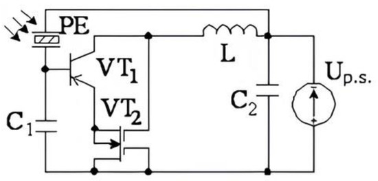
Figure 2.
Electrical circuit of the measuring transducer based on the metal–pyroelectric–semiconductor structure.
The circuit of the frequency-measuring converter consists of bipolar and field-effect transistors, which are powered by a constant voltage source Up.s. (Figure 2). In this BJT-MOS transistor structure, there is negative resistance on the collector-drain electrodes of transistors VT1 and VT2. Connecting an external inductance L to the collector-drain electrodes allows one to create a generator of electrical oscillations, the generation frequency of which clearly depends on the temperature.
Since the SPT is a dynamic system, the analysis of the studied structure will be carried out within the duration of the active pulse of heat radiation [12]. When the signal hits the sensitive element, the pyroelectric heats up, which results in the arising signal charging both the pyroelectric capacitor itself and the transistor input capacitance. The heat radiation power required to trigger the sensor is in the range of microwatts [13]. Therefore, a bipolar transistor with a pyroelectric film has high sensitivity. A potential of a certain polarity, which is applied to the base of the bipolar transistor, changes the voltage of the transistor structure with a pyroelectric film:
where U0 = 2.4 V; θ is the correction factor; Ube is the base-emitter voltage.
If the potential on one surface of the pyroelectric is constant and the potential on the other varies, then
where p is the pyroelectric coefficient; δ is the thickness of the pyroelectric; ΔT is the temperature change; ε is the dielectric constant of the pyroelectric material; and ε0 is the dielectric constant. By substituting the expression for the temperature change in the pyroelectric in (2), we obtain
where A is the area of the absorbing layer on the sensing element surface; η is the sensor emission coefficient; α is the coefficient characterizing the heat transfer by thermal conductivity and radiation; τ is a constant that does not depend on temperature and time; t is time; and T is the temperature of the incident radiation.
Combining (1) and (3), we obtain the dependence of the base-emitter voltage of a bipolar transistor with a pyroelectric film on temperature
Assuming that the sensor is switched on at the moment of radiation appearance, (4) can be rewritten as
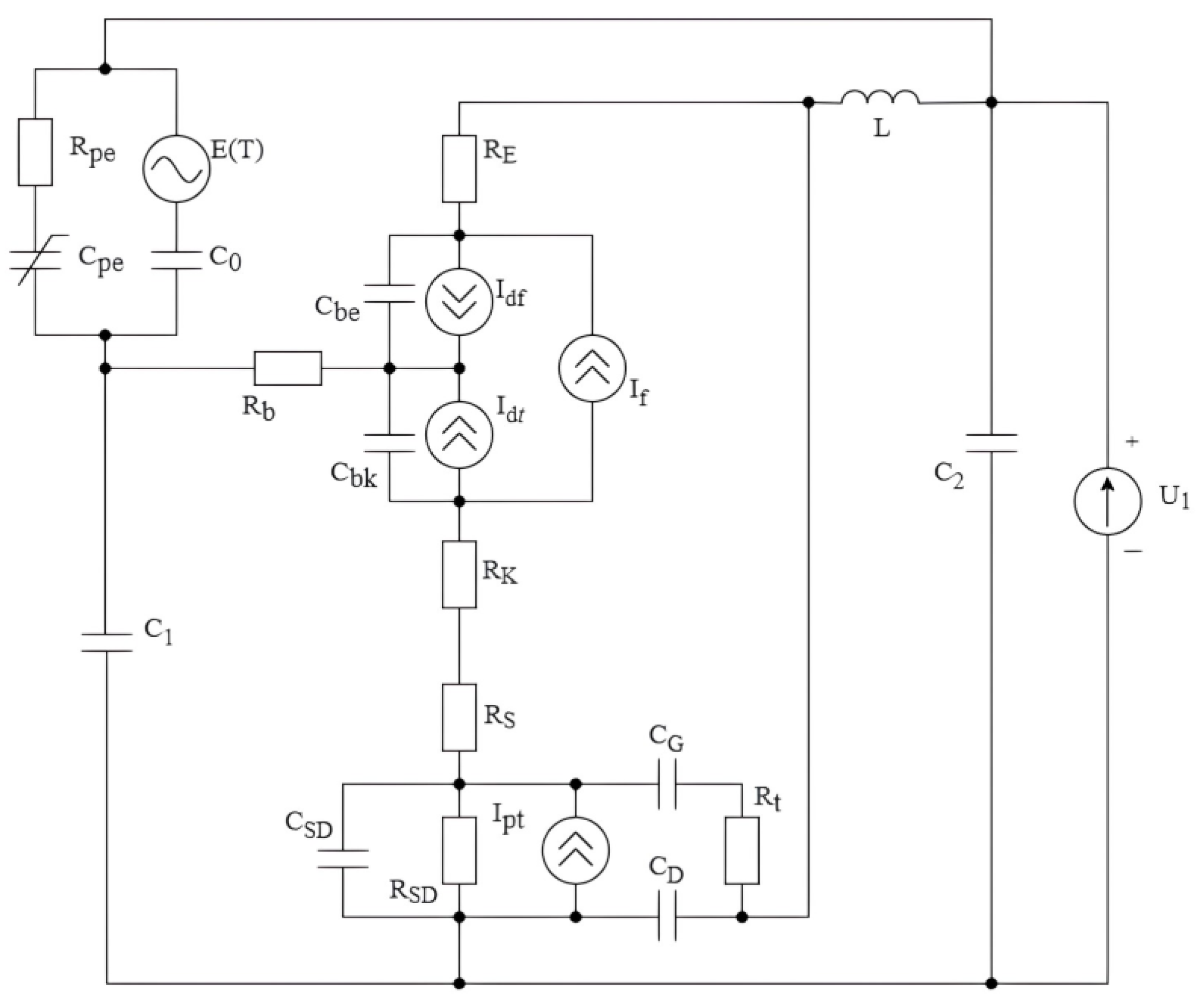
Changes in the human body temperature affect various parameters and characteristics of the transistor structure [14], namely, the width of the band gap of the semiconductor, the contact potential differences in transistor junctions, and the capacitances of transistor junctions [4]. This is reflected in the change in elements of the equivalent circuit, which is shown in Figure 3.
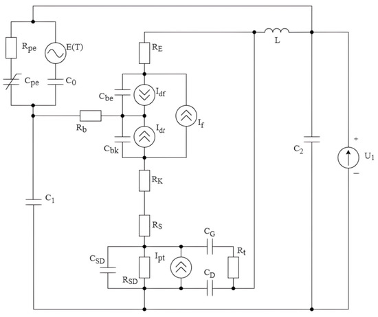
Figure 3.
Equivalent circuit of frequency-measuring transducers.
The equivalent circuit in Figure 3 uses the following notation: U1 is the power supply; R1 is the internal resistance of the power supply; L is the passive inductance; CPE is the nonlinear capacitance of the pyroelectric structure; C0 is the capacitance of the pyroelectric structure; RPE is the resistance of the pyroelectric structure; E(T) is the source of electric power of the pyroelectric structure; and C1 and C2 are circuit capacitances. Regarding elements of the equivalent circuit of the bipolar transistor, RB, RE, and RC are the volumetric resistances of the base, emitter, and collector; Cbe and Cbc are capacitances of the emitter and collector; If is the nonlinear source of the direct current of a bipolar transistor; and Idf and Idr are currents of the transistor’s internal transitions. Regarding elements of the equivalent circuit of a field-effect transistor, RD, RSD, and RS are resistances of the drain, source-drain, and source; CD, CSD, and CG are capacitances of the drain, source-drain, and gate; and Ipt is the nonlinear current source of the field-effect transistor.
We then consider the temperature dependences of the elements of the equivalent circuit of the transistor structure with negative resistance, which are necessary to build a mathematical model of the measuring transducer.
The dependence of the band gap width of the semiconductor on temperature is described by the following expression [4]:
where T is the temperature of the human body, s is the area of the p-n junction, EG0 is the width of the band gap at a normal temperature of 23 °C, and a and b are the temperature coefficients of the p-n junction. The contact potential difference of the emitter junction is determined by the following formula [5]:
where T0 is a normal temperature of 23 °C; Vt = kT/q is the junction temperature potential; k is the Boltzmann constant; q is the electron charge; and Uje is the contact difference of emitter junction potentials.
The contact difference of the collector junction potentials is represented by
where Ujc is the contact difference of the collector junction potentials.
Substituting Equation (6) into Equations (7) and (8), we obtain the equation of dependence of the junction voltage of the transistor structure of the measuring transducer on the human body temperature
The calculation of Equation (9) makes it possible to obtain a graphical representation of the dependence of the transistor structure of the sensor junction voltages on temperature changes.
As can be seen from the conversion scheme of Figure 3, the change in the voltage of the transistor structure transitions causes a change in the capacitance of the corresponding transistor structure transitions of the measuring converter. The change in the transistor junction capacitance, in turn, causes changes in the barrier capacitance of the sensor and the base-collector junction capacitance. Next, we determine these dependencies in analytical form.
The dependence of the collector junction capacitance at zero offset on the human body temperature is described by the following expression [6]:
where Mjc is a coefficient that takes into account the smoothness of the collector junction and Cjc is the collector junction capacitance at zero bias.
The dependence of the emitter junction capacitance on temperature at zero bias is described by the following expression [4]:
where Mje is a coefficient that takes into account the smoothness of the emitter junction and Cje is the capacitance of the emitter junction at zero bias.
The barrier capacity is described by the following expression [4]:
where Ube is the voltage between the base and the emitter of the bipolar transistor and Fc is the nonlinearity coefficient of the barrier capacitances of forward-biased junctions.
The capacitance of the base-collector junction depending on the temperature is as follows:
where Ubc is the voltage between the base and the bipolar transistor collector.
Substituting Equations (10) and (11) into Equations (12) and (13), we obtain the dependence of the capacity of the transistor structure of the measuring transducer on the change in the contact potential difference of the transistor structure sensor
Changing the capacitance of the transistor structure causes a change in the output frequency of the converter according to the Thompson formula
where Leqv is the equivalent inductance of the measuring transducer.
For the measuring transducer circuit shown in Figure 3, expression (15) will have the following form:
Formula (16) is the conversion function of the lambda-type temperature transducer.
The analytical dependence of the output frequency on the temperature of the human body F = f(T) can be obtained by successive substitutions of dependencies (9) and (14) into equation (16).
The sensitivity of the measuring transducer for a mobile robotic system is determined from Equation (16) as the first derivative of the temperature transformation function
To model the output signal of the measuring transducer, we use the method of alternating states [7].
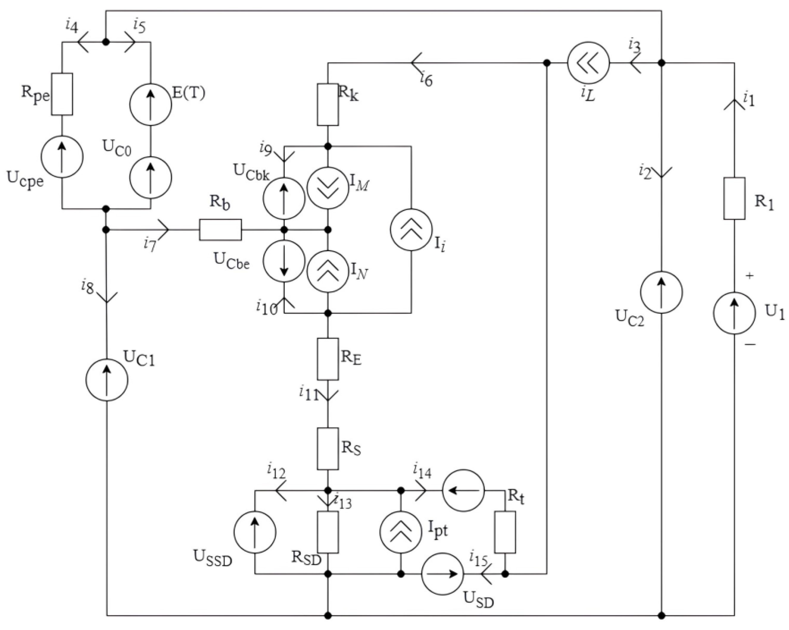
The equivalent circuit of the frequency-measuring transducers is shown in Figure 3. Next, we design a circuit where capacitances and inductances are replaced by ideal sources (Figure 4).

Figure 4.
Transformed equivalent circuit of the frequency-measuring transducers.
The direction of the injected sources Uck(t), Ucds(t), Ucp(t), and iL(t) is consistent with the positive direction for the state variables. In this case, the directions of the emf UC(t) are opposite to the direction of the current iC(t), and the directions of the current sources iL(t) coincide with uL(t). Since in the transformed equivalent circuit (Figure 4), there is no loop from voltage sources or cut from current sources, we proceed to the second stage.
Now, it is necessary to determine the currents through the input voltage sources (ic(t)) and voltages at the input current sources (UL(t)). To do this, we solve the system of Equation (18) for the circuit, which is formulated according to the laws of Ohm and Kirchhoff
After replacing the left side of the system of Equation (18) with the derivatives of the state variables, we obtain the system of states Equation (19) in an orderly form
The system of Equation (19) is nonlinear since it contains nonlinear dependent sources of currents Ipt, Ibit, Idf, and Idr and capacitances Ce and Cc as constituent elements. The calculation of nonlinear parameters was carried out using Equations (20)–(26).
where Ir is the nonlinear reverse current source of the bipolar transistor; IS is the saturation current; Vt is the junction temperature potential; NF and NR are the imperfection factors in normal and inverted modes; and BF and BR are the maximum current transfer coefficients in the circuit with the CE in normal and inverted modes. VBE = VB − VE and VBC = VB − VC—voltages are the internal points of the base emitter and base collector (for a p-n-p transistor, it is taken with the reverse sign as VBE = −(VB − VE) and VBC = −(VB − VC).
where Ibit is the current of the combined source and QB is the transistor transition imperfection coefficient.
where Idf and Idr are the currents of internal transitions of the base emitter and base collector.
where Ipt is the piecewise nonlinear current source of the field-effect transistor; β is the steepness of the transient response; VTO is the threshold voltage; KP is the specific steepness; Wd is the channel width; Ld is the channel length; and VGS = VG − VS and VDS = VD − VS are the voltages at the internal gate-drain and drain-source points (for a transistor with a p-channel, VGS = −(VG − VS), VDS = −(VD − VS) is taken with the opposite sign).
The bipolar transistor has diffusion and barrier capacitances. For emitter junction
and for the collector
where CJE and CJC are the capacitances of the emitter and collector junctions at zero offset, respectively; MJE and MJC are the smoothness coefficients of the junctions; and VJE and VJC are the contact potential differences in the junctions.
To verify the developed model, we used a program to calculate the output frequency of generation from the temperature value, acting on the sensitive element in the language of the Maple 13 Release 13.02 software package.
Theoretical and experimental studies have shown that the conversion function of the measuring transducer for the non-contact measurement of the human body temperature is almost linear. The relative deviation between the theoretical and experimental characteristics does not exceed 0.15%. Thus, the developed mathematical model of the measuring transducer is adequate.
2.3. Assessment of Measurement Errors
Errors exist in any measurement. Based on practical needs, a decision is made regarding the level of accuracy required. From this, we can conclude that measurement is characterized not only by the result, which is the numerical value of the measured quantity, but also by the error that is obtained.
Next, we determined the total error in the process of determining the value of the human body temperature using a non-contact frequency-measuring transducer. The causes of error are numerous and have a diverse nature associated with the following factors: the use of a non-contact temperature measurement method, the influence of the electrical circuit of the device, the inertia of the measurement process, and errors in converting the measured frequency into a digital code.
Next, we analyzed the errors that arise when determining the phase transitions of substances from the use of temperature-measuring instruments based on their radiation. The expressions of the corresponding error component can be determined from the temperature measurement equations by expanding them into a Taylor series in the vicinity of the measurement results of the arguments Ii,
where is the component of the methodological error caused by the discrepancy in the functional relationship between the quantities.
The instrumental component of the error depends on the quality of the measuring instrument itself and arises due to the imperfection of measuring instruments and the dependence of their properties on the influence of external conditions [10]. When measuring temperature by radiation, the instrumental error is caused by the inaccuracy of measuring the radiation flux from the object under study due to the influence of the parameters of the optical system, the electrical circuit, features of the radiation receiver, and changes in their characteristics over time.
The expression of the components of the radiation temperature measurement error is defined as the sum of partial derivatives of the expression of the conditional temperature by radiation flux intensities [8], which are perceived by a pyrometric transducer based on transistor structures with negative resistance. The general expression that describes the error component due to changes in the intensity of the radiation flux perceived by a non-contact frequency-measuring transducer is
where is the transfer coefficient of the instrumental error component of temperature measurement, the expression and value of which depend on the corresponding pyrometry method; depending on the method used; and i is the number of working spectral channels.
For the developed frequency-measuring transducer, based on the reactive properties of transistor structures with negative resistance, the error value (28) is 0.25%.
The accuracy of temperature measurement using radiation is also significantly affected by the methodological error of measurement. According to the theory of errors [3], methodological error is a component of measurement error caused by the inadequacy of the measurement object and its model used in the measurement. The main factors that cause methodological error in measuring temperature using radiation are the theoretical simplifications used (in particular, the use of the Wien formula and the failure to take into account the non-monochromaticity of spectral channels), the lack of reliable information about the radiation properties of the object under study, and neglecting the influence of background radiation and the intermediate medium.
The methodological error of frequency devices used to determine the phase transitions of substances is caused by the influence of the radiation properties of the object, the use of a limited spectral region when using frequency devices based on TSNR, and the influence of the intermediate medium through which radiation passes from the object to the measuring instrument.
The expression of the methodological error component of temperature measurement using radiation in determining the phase transformations of substances is defined as the sum of partial derivatives of the expression for determining the thermodynamic temperature using this method. The general expression of the methodological error component will be
where is the transfer coefficient of the methodological error component of temperature measurement, the values of which depend on the pyrometry method, and m and p are the coefficients of influence of the error components.
The value of the methodological error of the developed frequency-measuring transducer according to Equation (29) will be 0.33%. The methodological errors include an error due to the introduction of an incorrect value of the emissivity of the object; an error arising from a change in the intensity of the radiation flux; an error due to the dependence of the measurement results on the distance to the measurement object; an error due to incomplete filling of the field of view of the sensitive element by the measurement object; and an error due to the temperature of the sensitive element housing. The total methodological error of temperature measurement will be 0.42%.
Errors arising from the influence of the electrical circuit of the frequency-measuring converter are of the following natures:
- δ1—measurement error arising from the instability of the generator frequency.
- δ2—measurement error resulting from changes in ambient temperature.
- δ3—error due to instability of the power supply of the transistor structure.
- δ4—error due to own noise and external interference to the input circuit of the electronic frequency meter.
The value estimate is determined on the basis of the equation
where is the characteristic resistance of the circuit; L is the external inductance; C is the equivalent capacitance of the transistor structure; and A0 is the relative value of the oscillation amplitude in the zero approximation
where is the differential negative resistance; , is the resistance of the inductive element; Q is the quality factor of the circuit, (Q = 150); and , , , , and are the approximation coefficients determined from the system of equations
where ; ; ; and are the maximum and minimum current values on the descending section of the static frequency response of the frequency converter; and are the voltages corresponding to and ; is the offset voltage, which is counted from the origin in the figure of the device’s frequency response; and is the cyclic frequency.
According to the calculations made by Equations (30)–(32), the measurement error is 0.3%.
The measurement error resulting from the changes in ambient temperature is determined by
where is the frequency of generation when the ambient temperature changes by 1 °C and is the carrier frequency of the PFM.
If thermal stabilization of the frequency converter circuit is used, one can achieve a change in ambient temperature within 0.1 °C. Then, the error due to frequency deviation is
To determine the error associated with the change in the generation frequency due to fluctuations in the supply voltage, it is necessary to first find the change in the output frequency of the VFD due to a 1% change in the supply voltage. For this VFD scheme, the supply voltage is = 3 V, and then its change will be 0.03 V, which corresponds to a change in the output frequency of generation by 3000 Hz. The power supply instability error will be determined by
The LM7805 voltage regulator was used to stabilize the supply voltage. The linear stabilization of this chip is 5 mV, which corresponds to a change in the generation frequency of 300 Hz. Then, the error will be equal to
The error arising from intrinsic noise and extraneous interference is estimated experimentally. We denote the performance of the original instrument due to noise and interference as and the performance of the original instrument during the calibration process as . Then, the distribution of a random variable allows us to determine the mathematical expectation and standard deviation , hence
The total error of the frequency-measuring temperature transducer of non-crystalline semiconductors is defined as the result of the found errors
The total measurement error is equal to the sum of instrumental and methodological errors and is 0.7%.
Since the measured value is a function of time, due to the inertia of the measuring instruments and other reasons, a dynamic error occurs in the device for determining the phase transformations of materials, which is a component of the error [5]. For the developed frequency-measuring transducers based on the reactive properties of semiconductor materials, the switch-on time is about 20 ns, so the dynamic error resulting from determining the phase transformation temperature is five orders of magnitude less than the static errors of the device itself. In this case, the dynamic errors do not significantly affect the resulting error of the device so they are not considered in this paper.
2.4. Mobile Robotic System with the Proposed Pyroelectric Temperature Measurement Sensors
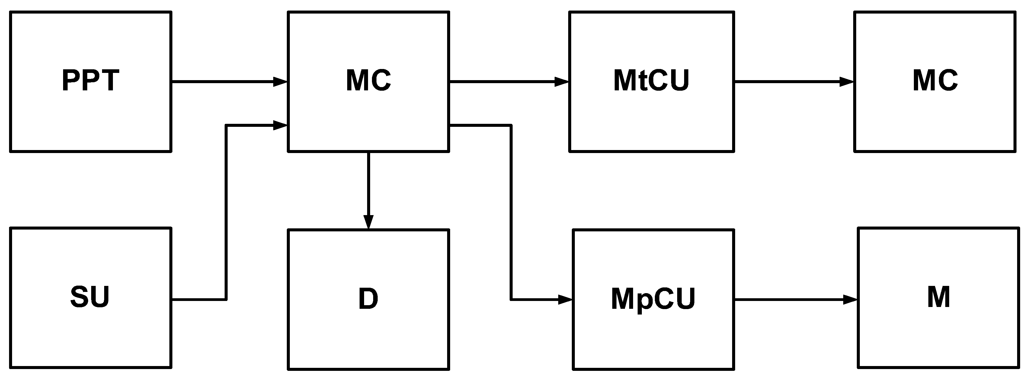
The proposed high-precision temperature sensor was installed on a mobile portable robot for the non-contact measurement of the human body temperature (MPRMT). The approach to the use of temperature sensors, combining them with other robotic and medical structures, is not new, but in contrast, has become more common in recent years [13,14,15]. The robot has a manipulator designed and printed on a 3D printer, as well as a Bluetooth module (this allows the control of the robot from a smartphone). The LCD display allows for the display of information about the current temperature and recommendations for further action. The block diagram of the mobile robotic system with a proposed pyroelectric temperature measurement sensor is shown in Figure 5. It consists of a microcontroller board (MC), which controls the MPRMT movement with the help of the motor unit (MU), controls the manipulator (M) movement, processes data from the sensor, and displays the measured temperature with certain recommendations on the LCD display (D). The MC used the Arduino Uno board, which has also become a popular technical solution in recent years [16,17,18,19,20]. The main reason for using the Arduino Uno board as the MC of the MPRMT is the advantages of the ATMEGA microcontroller, which are listed in [20]. The motor control unit (MtCU) and the manipulator control unit (MpCU) serve as interfaces between the MC and the MD and between the MC and the M, respectively. The Sensor Unit (SU) contains sensors that allow the MPRMT to move correctly, avoiding obstacles.
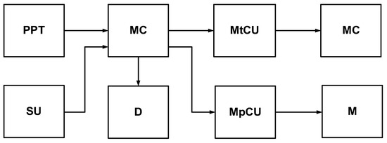
Figure 5.
Block diagram of the mobile portable robot for non-contact measurement of human body temperature.
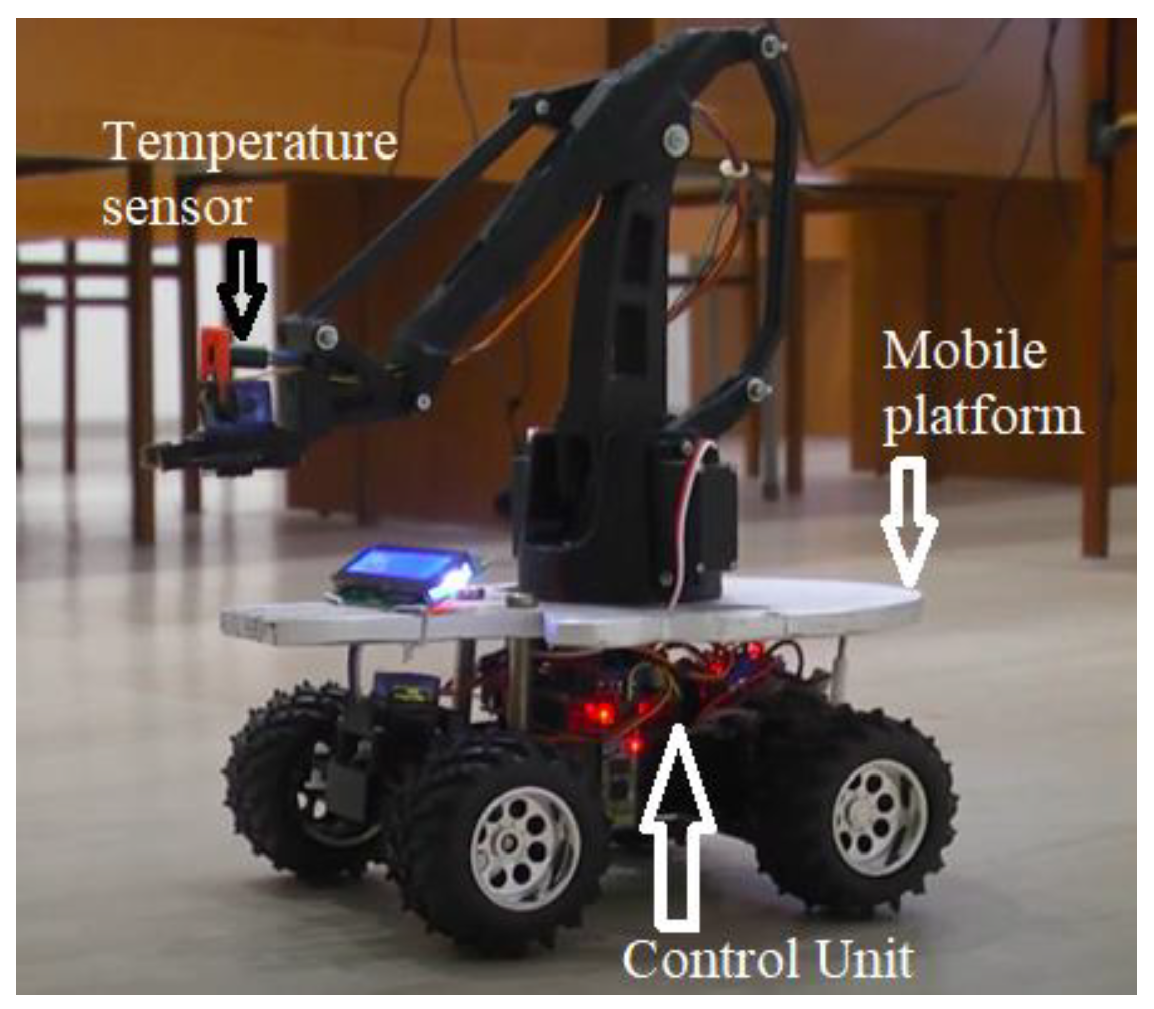
Figure 6 shows the hardware implementation of the mobile robotic system with a proposed pyroelectric temperature measurement sensor. It consists of three main parts: the mobile platform, the temperature sensor proposed by the authors, and the control unit.
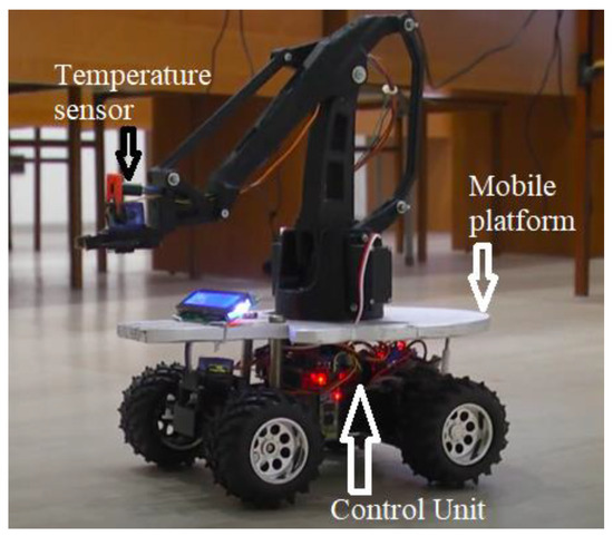
Figure 6.
Photo of the hardware implementation of the mobile robotic system with a proposed pyroelectric temperature measurement sensor.
The mobile platform serves as the foundation of the robotic system, providing mobility and stability. It is typically an Automated Guided Vehicle (AGV) or a similar mobile unit equipped with wheels and motors for navigation. The platform is designed to move smoothly across different surfaces and avoid obstacles using integrated sensors.
The chassis is constructed from lightweight yet durable materials to ensure stability and ease of movement. Motors are used to drive the wheels, enabling forward and backward movements.
Ultrasonic sensors and LiDAR are employed for obstacle detection and navigation. These sensors help the robot to map its environment and plan its path effectively.
The core component for temperature measurement is the proposed non-contact pyroelectric measurement sensor. This sensor measures the temperature of objects by detecting heat radiation and operates over the I2C protocol, allowing easy integration with microcontrollers like the Arduino Uno.
The control unit, consisting of the Arduino Uno Rev3 microcontroller equipped with the ATmega328p (Arduino S.r.l., Santa Liberata, Italy), is responsible for processing sensor data, managing navigation, and controlling the overall operation of the robot. It handles communication between sensors and actuators, ensuring real-time response. Integrated with the ESP-01 Wi-Fi module, the system gains access to a Wi-Fi network, enabling remote control and data transmission. This module allows the robot to send temperature data to a central server or a mobile device for further analysis and monitoring.
The software architecture includes algorithms for processing raw data from the temperature sensor and other navigation sensors, involving noise filtering, environmental compensation, and the conversion of sensor readings into meaningful temperature values. The software calculates body temperature based on the heat radiation detected by the sensor, compensating for ambient temperature and other factors that might affect the readings.
Operators can monitor and control the robot remotely through a user interface, which provides real-time feedback on the robot’s status, temperature readings, and navigation path. Developed on the Python Kivy framework, the mobile application connected via Wi-Fi enables users to control the robot and view temperature data, offering an intuitive interface for easy operation and monitoring. The robot is also equipped with a display screen to show temperature readings and other relevant information, while audio signals provide feedback on the robot’s status and ensure optimal positioning for temperature measurement.
External system analysis involved gathering and sending information for further evaluation and integration.
3. Results
3.1. Data Visualization
To effectively visualize the performance of the pyroelectric sensor for application in the mobile robotic system for the non-contact measurement of human body temperature, two key aspects will be presented: the graphical dependence of the output frequency of the sensor on temperature and the simulated output oscillations of the measuring transducer at different indicators of the measured temperature.
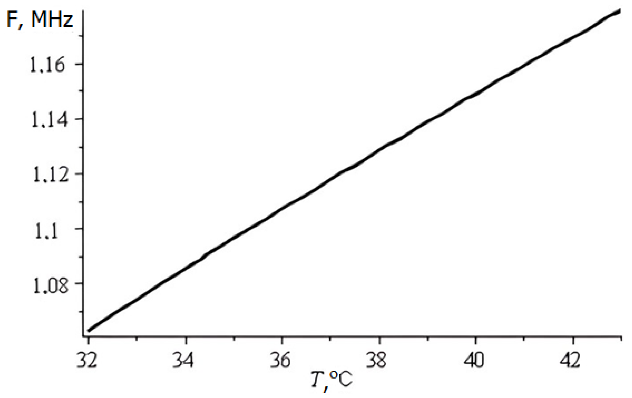
The non-contact temperature sensor employed in the robotic system utilizes the principle of heat radiation detection. The output frequency of the sensor is directly correlated with the measured temperature, as illustrated in Figure 7.

Figure 7.
Conversion function of the developed lambda-type measuring transducer.
The graph depicts a linear relationship between the output frequency of the sensor and the measured temperature within the operating range of the system. As the temperature increases, the output frequency of the sensor increases proportionally, allowing for accurate temperature measurements based on frequency readings.
This linear relationship is crucial for calibrating the sensor and ensuring precise temperature measurements across the entire operating range of the robotic system.
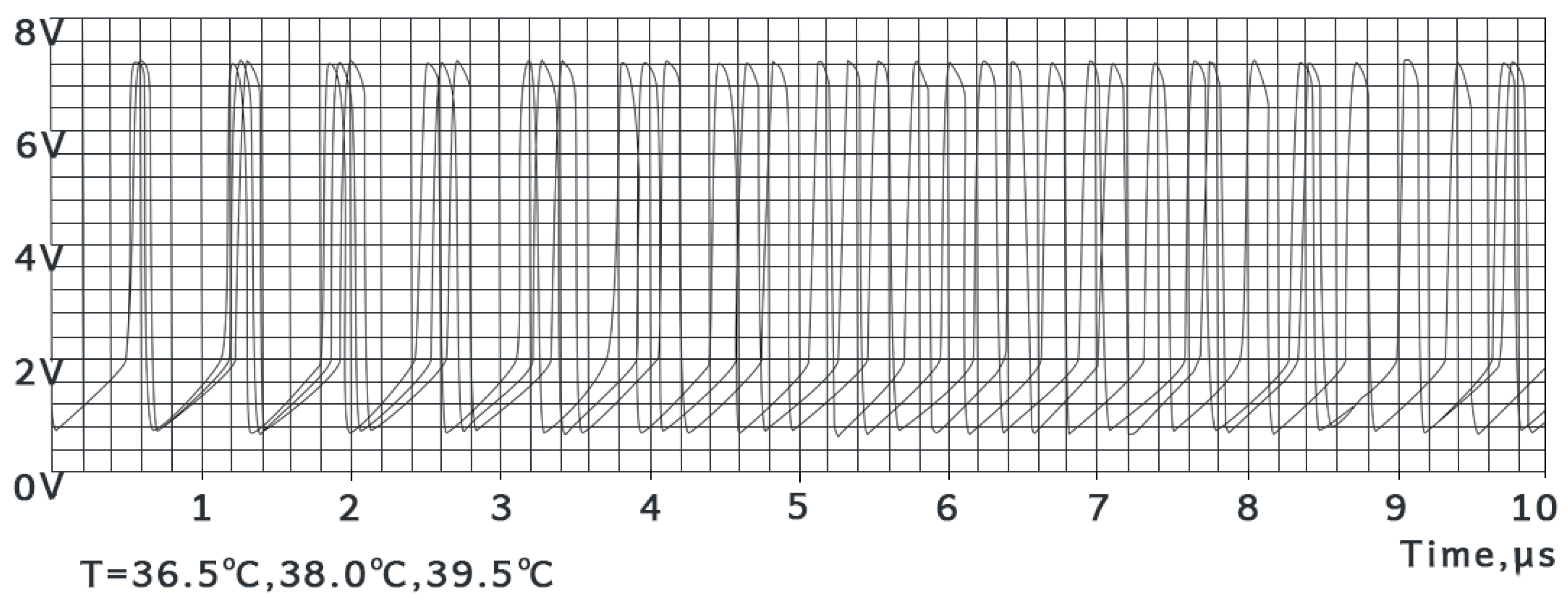
To evaluate the performance of the measuring transducer under different temperature conditions, simulations were conducted to analyze the output oscillations. Figure 8 presents the simulated output oscillations of the transducer at three different temperature indicators: 36.5 °C (normal body temperature), 38.0 °C (elevated temperature), and 39.5 °C (fever).
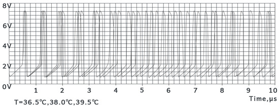
Figure 8.
Simulated output oscillations of the measuring transducer at different indicators of the measured temperature.
The calculation of the system (18) shows that when using this mathematical model of the lambda-type sensor to measure the temperature of the human body, there will be periodic oscillations at the output of the circuit. Figure 8 shows the simulated output oscillations (t = 0 … 10 µs) with the parameters given in [4]. The calculation shows that the oscillation frequency depends on the temperature change in the non-crystalline semiconductors. Figure 8 shows that with increasing temperature, the frequency of the output signal will decrease.
The simulated output oscillations demonstrate the transducer’s response to different temperature levels. As the temperature increases, the amplitude and frequency of the oscillations change accordingly, reflecting the variations in the measured heat radiation.
These simulations provide valuable insights into the transducer’s behavior and aid in the development of signal-processing algorithms for accurate temperature measurement. By analyzing the output oscillations, researchers can optimize the transducer design, improve signal filtering techniques, and enhance the overall measurement accuracy of the robotic system.
The data visualization presented in this section highlights the critical relationships between the temperature and the sensor output, as well as the simulated performance of the measuring transducer. These visualizations serve as valuable tools for understanding the system’s behavior, calibrating components, and optimizing the overall measurement process, ultimately contributing to the development of a reliable and accurate mobile robotic system for non-contact temperature measurement.
3.2. System Performance
The performance of the pyroelectric sensor for application in a mobile robotic system for the non-contact measurement of human body temperature was evaluated through a series of experiments conducted on several hundred volunteers at the Department of Computer Science of Vinnytsia National Technical University during the COVID-19 pandemic in September 2020. The following section details the key performance metrics of the system, including the accuracy, precision, response time, and reliability of temperature measurements.
Accuracy refers to the closeness of the measured temperature values to the true body temperature. The system’s accuracy was assessed by comparing the temperature readings obtained from the non-contact pyroelectric sensors with those from standard clinical thermometers.
Regarding measurement comparison, the system’s temperature readings were compared against clinical thermometer readings for a sample of 300 volunteers. The results showed a mean absolute error (MAE) of ±0.1 °C, indicating high accuracy in temperature measurement.
Concerning calibration, the pyroelectric sensors were calibrated using a blackbody radiation source to ensure accurate temperature readings across a range of temperatures. The calibration process involved setting the emissivity of the sensors to match the emissivity of human skin, which is typically around 0.98 [21].
Precision refers to the consistency of the temperature measurements when repeated under the same conditions. The system’s precision was evaluated by taking multiple temperature readings of the same individual over a short period.
Regarding repeatability, the system demonstrated a repeatability of ±0.1 °C, with minimal variation in temperature readings when measured multiple times within a span of 30 s. This high level of precision ensures reliable temperature monitoring [22].
A statistical analysis of the temperature data collected from 300 volunteers showed a standard deviation of 0.2 °C, further confirming the system’s precision in temperature measurement.
Response time is the duration taken by the system to provide a temperature reading after initiating the measurement. The response time of the mobile robotic system was evaluated based on the time taken by the pyroelectric sensors to stabilize and provide a consistent reading.
Regarding sensor response time, the pyroelectric sensors used in the system have a response time of 500 milliseconds, allowing for rapid temperature measurements [22].
The overall system response time, including the time taken for the robot to position itself and initiate the measurement, was approximately 2 s. This quick response time enables efficient temperature screening of large groups of people in a short period [23].
Reliability refers to the system’s ability to consistently provide accurate and precise temperature measurements over extended periods and under varying conditions. The reliability of the system was assessed through long-term testing and environmental robustness.
Regarding long-term testing, the system was tested continuously over a period of one month, during which it maintained consistent performance with no significant drift in temperature readings. This long-term stability indicates the system’s reliability for prolonged use [24].
To assess environmental robustness, the system was tested in different environmental conditions, including variations in ambient temperature and humidity. The results showed that the system could maintain accurate and precise temperature measurements within an ambient temperature range of 15 °C to 35 °C and relative humidity levels of 30% to 70% [23,24].
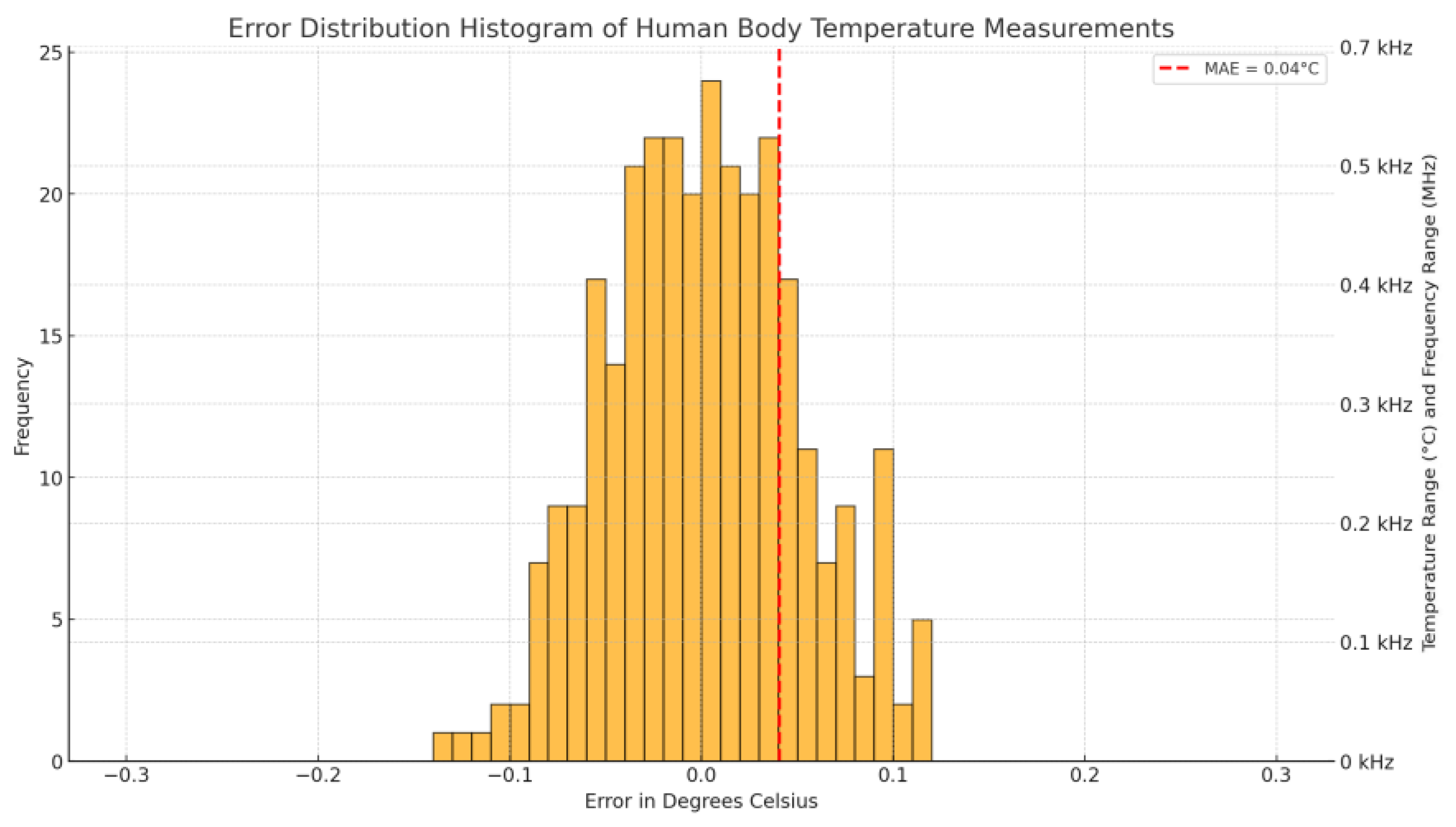
To provide a more comprehensive view of the system’s performance, we conducted an error distribution analysis on the temperature measurements of 300 volunteers. Figure 9 shows a histogram of the temperature measurement errors.

Figure 9.
Histogram of temperature measurement errors for 300 volunteers.
The X-axis (Figure 9) represents the measurement error in degrees Celsius. It is divided into small intervals (e.g., 0.01 °C or 0.02 °C) to show a detailed distribution of errors. The range might span from −0.3 °C to +0.3 °C to capture the full spectrum of potential measurement deviations.
The left Y-axis (Figure 9) represents the frequency of each error interval, showing how often each specific error value occurred in the measurements.
The right Y-axis (Figure 9) combines the temperature and frequency ranges, with temperatures from 36.25 °C to 36.85 °C and frequencies from 0 kHz to 0.7 kHz.
Regarding the plot details in Figure 9:
Each bar in the histogram represents the number of occurrences (frequency) of a specific measurement error within the defined intervals.
The gradient background along the right Y-axis indicates the temperature range from 36.25 °C to 36.85 °C.
The frequency range from 0 kHz to 0.7 kHz is overlaid as a secondary scale or gradient on the right Y-axis.
A vertical line or marker indicates the Mean Absolute Error (MAE) for reference.
The performance metrics of the pyroelectric sensor for application in a mobile robotic system for the non-contact measurement of human body temperature are summarized in Table 1.

Table 1.
Summary of performance metrics.
The pyroelectric sensor applied in a mobile robotic system for the non-contact measurement of human body temperature demonstrated high accuracy and precision, a rapid response time, and reliability in various testing conditions. These performance metrics validate the system’s effectiveness for temperature-screening applications, particularly in scenarios requiring quick and non-invasive measurements, such as during the COVID-19 pandemic. The system’s robust performance ensures its suitability for deployment in diverse environments, contributing to enhanced public health monitoring and safety.
3.3. Comparative Analysis
The pyroelectric sensor applied in a mobile robotic system for the non-contact measurement of human body temperature offers several advantages over traditional methods and other existing systems. This section compares the performance and features of our system with other commonly used temperature measurement technologies, such as infrared (IR) thermometers and thermal imaging cameras, to highlight the improvements and benefits of our approach.
3.3.1. Comparison with Infrared (IR) Thermometers
IR thermometers, also known as spot pyrometers, measure the temperature of a single spot on the target. While they are useful for quick, point-specific measurements, their accuracy can be affected by the distance from the target and the size of the spot being measured. The average IR thermometer has a distance-to-spot (D–S) ratio that limits its effective range and precision [25,26]. In contrast, our pyroelectric temperature measurement sensor has a higher D–S ratio, allowing for more accurate and precise temperature measurements from a greater distance. The system demonstrated a mean absolute error (MAE) of ±0.1 °C and repeatability of ±0.03 °C, which are superior to typical IR thermometers [27,28].
IR thermometers require manual operation to scan each individual spot, making them time-consuming and less efficient for screening large groups of people. Operators must know the exact location of the hotspot to measure it accurately, which can be challenging in dynamic environments [25,26]. Our device with its pyroelectric temperature measurement sensor can autonomously navigate and scan large areas, providing comprehensive temperature readings for multiple individuals simultaneously. This capability significantly enhances efficiency and reduces the time required for temperature screening in high-traffic areas [25,26].
3.3.2. Comparison with Thermal Imaging Cameras
Thermal cameras provide a detailed thermal image of the target area, allowing for the identification of hotspots and temperature variations across a larger surface. They can measure thousands of spot temperatures simultaneously, offering a comprehensive view of the thermal profile [25,26]. Our system integrates high-resolution thermal imaging sensors, enabling it to capture detailed thermal images and identify temperature anomalies with high precision. The system’s ability to process and analyze thermal data in real time ensures accurate and reliable temperature measurements [25,26].
Advanced thermal cameras can measure temperatures from longer distances due to their superior optics and higher D–S ratios. However, they are typically stationary and require manual operation to adjust the field of view and focus on specific areas [25,26]. In contrast, our temperature measurement system combines the advantages of thermal imaging with mobility, allowing it to perform temperature measurements from various angles and distances. The system’s autonomous navigation and adjustable sensors provide flexibility in different environments, making it suitable for dynamic and crowded settings [25,26].
3.3.3. Advantages of the Mobile Robotic System
One of the key advantages of our mobile robotic system is its ability to operate autonomously. Unlike IR thermometers and stationary thermal cameras, the robotic system can navigate through environments, avoiding obstacles and adjusting its position to ensure optimal temperature measurements. This autonomy reduces the need for human intervention, minimizing the risk of virus transmission and enhancing safety [25,26].
The system is equipped with intelligent software that processes thermal data in real time, providing immediate feedback and alerts for abnormal temperature readings. This feature is particularly useful for rapid screening in public spaces, allowing for the quick identification and isolation of individuals with elevated body temperatures [25,26].
The mobile robotic system offers a user-friendly interface and seamless integration with mobile applications, enabling operators to monitor and control the system remotely. The real-time data visualization and reporting capabilities enhance the overall user experience, making the system accessible and easy to use for various applications [25,26].
In summary, the pyroelectric sensor for application in a mobile robotic system for the non-contact measurement of human body temperature demonstrates significant improvements over traditional IR thermometers and stationary thermal imaging cameras. Its high accuracy, precision, autonomous operation, and real-time data-processing capabilities make it a superior solution for temperature screening in diverse environments. The system’s ability to efficiently and safely monitor large groups of people highlights its potential for widespread adoption in public health monitoring and safety measures, particularly during pandemics like COVID-19.
4. Discussion
4.1. Implications for Practice
The development and implementation of the pyroelectric sensor for application in a mobile robotic system for the non-contact measurement of human body temperature have demonstrated promising results and practical implications in various settings. A photo with testing of the practical application of the mobile robot at the Department of Computer Science at Vinnytsia National Technical University is shown in Figure 10.
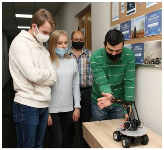
Figure 10.
Photo of the mobile portable robot for non-contact measurement of human body temperature.
Temperature measurement was tested on several hundred volunteers and showed quite adequate results. Testing was started in September 2020 at the Department of Computer Science of Vinnytsia National Technical University. Then the campaign “Responsible IT Education” was launched. The purpose of the campaign is to encourage students to be cautious during the pandemic, and at the same time, encourage research activities and generate creative ideas and further preparation of applied projects to prevent the infection and spread of COVID-19 [29,30,31]. It is important to note that this testing demonstrated a much greater willingness of the participants to undergo temperature control at the MPRVT, rather than with the use of special personnel.
The work was performed as part of the implementation and development of the BioArt project in a remote format related to COVID-19 quarantine (“Innovative Multidisciplinary Curriculum in Artificial Implants for Bio-Engineering Bachelor Science/Master Science Degrees”).
4.2. Future Work
The development and testing of the pyroelectric sensor for application in a mobile robotic system for the non-contact measurement of human body temperature have yielded promising results, demonstrating the system’s effectiveness and acceptance among participants. However, there are several areas for future research and development to further enhance the system’s capabilities and address existing challenges.
While the current system has shown adequate results, further improvements in sensor accuracy and calibration are essential. Future work should focus on developing more sophisticated calibration methods to account for environmental variables such as ambient temperature and humidity. This could involve integrating additional sensors to continuously monitor and compensate for these factors in real time [32,33]. Refining thermal compensation algorithms to improve the accuracy of temperature measurements, especially in dynamic environments where thermal gradients and shocks are prevalent, is also crucial [34,35].
Expanding the system’s capabilities to monitor additional vital signs, such as heart rate and respiratory rate, can provide a more comprehensive health assessment. This could involve incorporating additional sensors, such as photoplethysmography (PPG) sensors for heart-rate monitoring and respiratory sensors for breathing-rate measurement [35]. Developing algorithms to fuse data from multiple sensors can enhance the overall accuracy and reliability of the health monitoring system [35].
Enhancing the user interface and experience is crucial for wider adoption and usability. Future work should aim to design intuitive and user-friendly interfaces for both operators and end-users, ensuring ease of use and accessibility [35]. Implementing real-time feedback mechanisms to provide immediate results and alerts can improve the system’s responsiveness and utility in various settings [35].
Ensuring the system’s robustness and reliability across different environments is critical. Future research should focus on conducting extensive testing in diverse environments, including outdoor settings, to evaluate the system’s performance under varying conditions [33,35]. Improving the durability and resilience of the system’s components to withstand harsh conditions and prolonged use is also important [36].
Addressing regulatory and ethical considerations is essential for the system’s deployment. Future work should include collaborating with regulatory bodies to ensure compliance with health and safety standards and facilitating the system’s approval and adoption in healthcare settings [35]. Developing ethical guidelines for the use of non-contact temperature measurement systems is necessary to ensure privacy and data security for users [35].
To validate the system’s effectiveness and scalability, large-scale deployment and field trials are necessary. Future efforts should focus on implementing pilot programs in various settings, such as schools, hospitals, and public spaces, to gather real-world data and feedback [35]. Conducting longitudinal studies to assess the system’s long-term performance and impact on public health monitoring and safety is also recommended [35].
Integrating the mobile robotic system with broader health monitoring and management systems can enhance its utility. Future work should explore ensuring interoperability with existing health information systems and electronic health records (EHRs) to streamline data sharing and analysis [35]. Leveraging artificial intelligence and machine learning algorithms to analyze collected data, identify patterns, and provide predictive insights for proactive health management can further extend the system’s capabilities [35].
In conclusion, while the pyroelectric sensor for the non-contact measurement of human body temperature for application in mobile robotic systems has demonstrated significant potential, ongoing research and development are essential to address existing challenges and enhance its capabilities. By focusing on sensor accuracy, multi-sensor integration, user experience, environmental robustness, regulatory compliance, large-scale deployment, and broader system integration, future work can ensure the system’s effectiveness and impact in various applications, ultimately contributing to improved public health and safety.
5. Conclusions
The possibility of using industrial pyroelectric detectors to measure the human body’s temperature is shown. In addition, the example of the usage of a lambda-type self-oscillating system shows the possibility of increasing the accuracy and sensitivity of non-contact thermometers based on industrial pyroelectric detectors.
Based on the equivalent scheme of a contactless pyroelectric thermometer, a system of equations of state variables was compiled, the solution of which allowed us to obtain the thermometer conversion function and graphical representation of the output signal in the Maple 13 Release 13.02 software package, which can be used for engineering calculations of a contactless infrared thermometer.
A non-contact pyroelectric thermometer for application in a mobile robotic system with an accuracy of 0.1 °C and a sensitivity of 10 kHz/°C in the temperature measurement range from 32 to 43 °C has been developed. The authors have successfully implemented an experimental model of the device for use in mobile robotic systems. This practical application has yielded new results from experimental studies, which have further confirmed the correctness and adequacy of the proposed mathematical model.
It is advisable to use the mobile robotic system in various educational institutions, organizations, establishments, hospitals, during mass events indoors, etc. As the testing of the system at the Department of Computer Science of Vinnytsia National Technical University showed, students showed a significantly increased desire to undergo temperature monitoring.
It is planned to develop several options for the general appearance of the mobile robotic system to increase the trust and desire to undergo such monitoring for different groups of people (for example, for a kindergarten, the robot can be made in the form of some kind of animal).
In the future, it is planned to improve the proposed mobile robotic system by adding a camera for recognizing people. This will allow it to keep a log monitoring the temperature of each person and can be useful both for the person (for example, for early responses to possible changes in health) and for medical workers who serve a particular institution where this temperature measurement system is installed.
Author Contributions
Conceptualization, S.B. and A.S.; methodology, S.B.; software, I.A.; validation, A.S. and M.B.; formal analysis, I.A.; investigation, M.B.; resources, A.R.; data curation, S.B.; writing—original draft preparation, S.B. and A.S.; writing—review and editing, V.K.; visualization, A.R.; supervision, A.S.; project administration, V.K.; funding acquisition, V.K. All authors have read and agreed to the published version of the manuscript.
Funding
This research is part of the project No. 2022/45/P/ST7/03450 co-funded by the National Science Centre and the European Union Framework Programme for Research and Innovation Horizon 2020 under the Marie Skłodowska-Curie grant agreement No. 945339.
Institutional Review Board Statement
The study was conducted in accordance with the Declaration of Helsinki, and approved by the Ethics Committee of Faculty of Information Electronic Systems of the Vinnytsia National Technical University (protocol code 414, date of approval 24 June 2024).
Informed Consent Statement
Informed consent was obtained from all subjects involved in the study.
Data Availability Statement
Most data are contained within the article. All the data are available upon request due to restrictions, e.g., privacy or ethics.
Acknowledgments
The authors are grateful to all colleagues and institutions that contributed to the research and made it possible to publish its results.
Conflicts of Interest
The authors declare no conflicts of interest.
References
- European Centre for Disease Prevention and Control. Available online: https://www.ecdc.europa.eu/en/COVID-19 (accessed on 2 May 2024).
- World Health Organization (WHO). Available online: https://covid19.who.int/ (accessed on 2 May 2024).
- Morris, A.S.; Langari, R. Measurement and Instrumentation: Theory and Application, 3rd ed.; Academic Press: Cambridge, MA, USA, 2020; 736p, ISBN 9780128171417. [Google Scholar]
- Sze, S.M.; Li, Y.; Kwok, K.N. Physics of Semiconductor Devices, 4th ed.; Wiley: Hoboken, NJ, USA, 2021; 944p, ISBN 9781119429111. [Google Scholar]
- Osadchuk, A.; Semenov, A.; Baraban, S.; Semenova, E.; Koval, K.O. Noncontact infrared thermometer based on a self-oscillating lambda type system for measuring human body’s temperature. In Proceedings of the CriMiCo–2013 23rd International Crimean Conference Microwave and Telecommunication Technology, Sevastopol, Ukraine, 8–14 September 2013; pp. 1069–1070, 6652661. [Google Scholar]
- Semenov, A.; Baraban, S.; Osadchuk, O.; Semenova, O.; Koval, K.; Savytskyi, A. Microelectronic Pyroelectric Measuring Transducers. In Proceedings of the 4th International Conference on Nanotechnologies and Biomedical Engineering, ICNBME 2019, Chisinau, Moldova, 18 September 2019; IFMBE Proceedings; Tiginyanu, I., Sontea, V., Railean, S., Eds.; Springer: Cham, Switzerland; Volume 77. [CrossRef]
- Semenov, A.; Osadchuk, O.; Semenova, O.; Baraban, S.; Voznyak, O.; Rudyk, A.; Koval, K. Research of Dynamic Processes in the Deterministic Chaos Oscillator Based on the Colpitts Scheme and Optimization of Its Self-oscillatory System Parameters. In Data-Centric Business and Applications. Lecture Notes on Data Engineering and Communications Technologies; Radivilova, T., Ageyev, D., Kryvinska, N., Eds.; Springer: Cham, Switzerland, 2020; Volume 48. [Google Scholar] [CrossRef]
- Geng, J.; Ke, L.; Wei, K. A Precision Temperature Measurement Solution with High EMC Performance Using an RTD. ADI Analog. Dialogue. 2021, 55, 622–628. [Google Scholar]
- L’Orange, C.; Neymark, G.; Carter, E.; Volckens, J. A High-Throughput, Robotic System for Analysis of Aerosol Sampling Filters. Aerosol Air Qual. Res. 2021, 21, 210037. [Google Scholar] [CrossRef] [PubMed]
- Stanimirović, I.; Stanimirović, Z. Introductory Chapter: Temperature Sensing–The Book; IntechOpen: London, UK, 2018. [Google Scholar] [CrossRef]
- Dolibog, P.; Pietrzyk, B.; Kierszniok, K.; Pawlicki, K. Comparative Analysis of Human Body Temperatures Measured with Noncontact and Contact Thermometers. Healthcare 2022, 10, 331. [Google Scholar] [CrossRef] [PubMed]
- Peron, P. The choice of the method for body temperature measurement in intensive care patients: A literature review. Prof. Infermieristiche 2010, 63, 99–105. [Google Scholar]
- Zhang, L.; Zhu, Y.; Jiang, M.; Wu, Y.; Deng, K.; Ni, Q. Body Temperature Monitoring for Regular COVID-19 Prevention Based on Human Daily Activity Recognition. Sensors 2021, 21, 7540. [Google Scholar] [CrossRef] [PubMed]
- Vivek, R.; Varun, K.; Satish, K.; Dubey, G.; Sayeed, K.; Chandra, S. Noncontact temperature measurement of human hand skin using volume phase holographic optical element based digital holographic interferometer. Opt. Lasers Eng. 2022, 151, 106886. [Google Scholar] [CrossRef]
- Zukowski, M.; Matus, K.; Pawluczuk, E.; Kondratiuk, M.; Ambroziak, L. Patients Temperature Measurement System for Medical Robotic Assistan. In Proceedings of the AIP Conference Proceedings, Mechatronics Systems And Materials 2018, Zakopane, Poland, 4–6 June 2018; Volume 2029, p. 020084. [Google Scholar] [CrossRef]
- Deeksha, S.; Awanish, K.; Shivsani, D. Measurement of Temperature and Humidity by using Arduino Tool and DHT11. Int. Res. J. Eng. Technol. (IRJET) 2018, 5, 876–878. [Google Scholar]
- Sarkar, A. Design of Automatic Hand Sanitizer with Temperature Sensing. Int. J. Innov. Sci. Res. Technol. 2020, 5, 1269–1275. [Google Scholar]
- Mamun, M.; Hossain, M.; Rahman, M.; Abdullah, M.; Hossain, M. Design and Development of Arduino Based Contactless Thermometer. IITM J. Manag. IT 2020, 11, 59–65. [Google Scholar]
- Alcoran-Alvarez, G.A.; Garcia, M.; Alvarez, D. Automated Social Distancing Gate with Non-Contact Body Temperature Monitoring Using Arduino Uno. Int. Res. J. Eng. Technol. 2020, 7, 4351–4356. [Google Scholar]
- Samuel, N. Design and Implementation of a Contactless Infrared thermometer with Automatic Hand Sanitizer Dispenser using ATMEGA Microcontroller. Int. J. Eng. Inf. Syst. 2020, 4, 114–119. [Google Scholar]
- Infrared Thermometer Calibration—A Complete Guide. Available online: https://www.fluke.com/en-us/learn/blog/calibration/infrared-thermometer-calibration (accessed on 2 May 2024).
- Infrared Thermometer. Available online: https://www.amazon.com/Thermometer-Temperature-26%C2%B0F-1022%C2%B0F-32%C2%B0C%EF%BD%9E550%C2%B0C-Refrigerator/dp/B073YMQCVG (accessed on 2 May 2024).
- Su, Y.; Ma, C.; Chen, J.; Wu, H.; Luo, W.; Peng, Y.; Luo, Z.; Li, L.; Tan, Y.; Omisore, O.; et al. Highly Sensitive Flexible Temperature Sensors for Human Body Temperature Monitoring: A Review. Nanoscale Res. Lett. 2020, 15, 200. [Google Scholar] [CrossRef] [PubMed]
- Dyer, B.; Biglarbegian, M.; Aliabadi, A. The autonomous robotic environmental sensor (ARES). Sci. Technol. Built Environ. 2021, 27, 1461–1472. [Google Scholar] [CrossRef]
- What’s the Difference between IR Thermometers and Thermal Cameras? Available online: https://www.flir.com/discover/instruments/whats-the-difference-between-ir-thermometers-and-thermal-cameras/ (accessed on 2 May 2024).
- Pros & Cons: Thermal Imaging Camera vs Gun Thermometer. Available online: https://scarlet-tech.com/know-how-pros-cons-thermal-imaging-camera-vs-gun-thermometer/ (accessed on 2 May 2024).
- Mah, A.J.; Ghazi Zadeh, L.; Khoshnam Tehrani, M.; Askari, S.; Gandjbakhche, A.H.; Shadgan, B. Studying the Accuracy and Function of Different Thermometry Techniques for Measuring Body Temperature. Biology 2021, 10, 1327. [Google Scholar] [CrossRef] [PubMed]
- Khaksari, K.; Nguyen, T.; Hill, B.Y.; Perrault, J.; Gorti, V.; Blick, E.; Gonzalez Cano, T.; Shadgan, B.; Quang, T.; Malpani, R.; et al. Review of the Efficacy of Infrared Thermography for Screening Infectious Diseases with Applications to COVID-19. J. Med. Imaging 2021, 8, 010901. [Google Scholar] [CrossRef] [PubMed]
- VNTU Has Developed a “Pilot Version” of a Portable Robot for Contactless Measurement of Human Body Temperature. Available online: https://mon.gov.ua/ua/news/u-vntu-rozrobili-pilotnu-versiyu-portativnogo-robota-dlya-bezkontaktnogo-vimiryuvannya-temperaturi-tila-lyudini (accessed on 2 May 2024).
- A Robot for Measuring Body Temperature Has Been Developed at VNTU. Available online: https://www.myvin.com.ua/news/11576-u-vntu-rozrobyly-robota-dlia-vymiriuvannia-temperatury-tila (accessed on 2 May 2024).
- A Robot Will Measure Body Temperature at Vinnytsia National Technical University. Available online: https://misto.vn.ua/osvita/u-vinnickomu-nacionalnomu-texnichnomu-universiteti-temperaturu-tila-vimiryuvatime-robot (accessed on 2 May 2024).
- Goh, N.W.-J.; Poh, J.-J.; Yeo, J.Y.; Aw, B.J.-J.; Lai, S.C.; Cheng, J.J.W.; Tan, C.Y.L.; Gan, S.K.-E. Design and Development of a Low Cost, Non-Contact Infrared Thermometer with Range Compensation. Sensors 2021, 21, 3817. [Google Scholar] [CrossRef] [PubMed]
- An Intelligent Approach to Eliminating Thermal Disturbances in Non-Contact Temperature Measurement. Available online: https://www.melexis.com/en/tech-talks/eliminating-thermal-disturbances-in-non-contact-temperature-measurement (accessed on 2 May 2024).
- Koritsoglou, K.; Christou, V.; Ntritsos, G.; Tsoumanis, G.; Tsipouras, M.G.; Giannakeas, N.; Tzallas, A.T. Improving the Accuracy of Low-Cost Sensor Measurements for Freezer Automation. Sensors 2020, 20, 6389. [Google Scholar] [CrossRef] [PubMed]
- Huang, H.-W.; Chen, J.; Chai, P.R.; Ehmke, C.; Rupp, P.; Dadabhoy, F.Z.; Feng, A.; Li, C.; Thomas, A.J.; da Silva, M.; et al. Mobile Robotic Platform for Contactless Vital Sign Monitoring. Cyborg Bionic Syst. 2022. [Google Scholar] [CrossRef] [PubMed]
- Hegde, C.; Su, J.; Tan, J.M.R.; He, K.; Chen, X.; Magdassi, S. Sensing in Soft Robotics. ACS Nano 2023, 17, 15277–15307. [Google Scholar] [CrossRef] [PubMed]

Disclaimer/Publisher’s Note: The statements, opinions and data contained in all publications are solely those of the individual author(s) and contributor(s) and not of MDPI and/or the editor(s). MDPI and/or the editor(s) disclaim responsibility for any injury to people or property resulting from any ideas, methods, instructions or products referred to in the content. |
© 2024 by the authors. Licensee MDPI, Basel, Switzerland. This article is an open access article distributed under the terms and conditions of the Creative Commons Attribution (CC BY) license (https://creativecommons.org/licenses/by/4.0/).