
Bearing Faults Diagnosis by Current Envelope Analysis under Direct Torque Control Based on Neural Networks and Fuzzy Logic—A Comparative Study
 , ,
, ,  ,
,
Abstract
:1. Introduction
- Contribution to the diagnosis of BFs of an SCIM with a DTC control by MCSA by analyzing the spectrum of the envelope current (ECS) extracted by the HT.
- Measurement and comparison of the impact of improving DTC control by making simulations first in the case of conventional DTC (CDTC), then in the case of an ANN DTC, and finally with an FLDTC. The comparison of these three DTC control modes concerns electromagnetic torque, rotational speed, stator current THD, and ECC.
2. Modeling of the SCIM and BFs
2.1. SCIM Model
- The electrical equations are as follows:
- The magnetic equations are as follows:
- The mechanical equations are as follows:
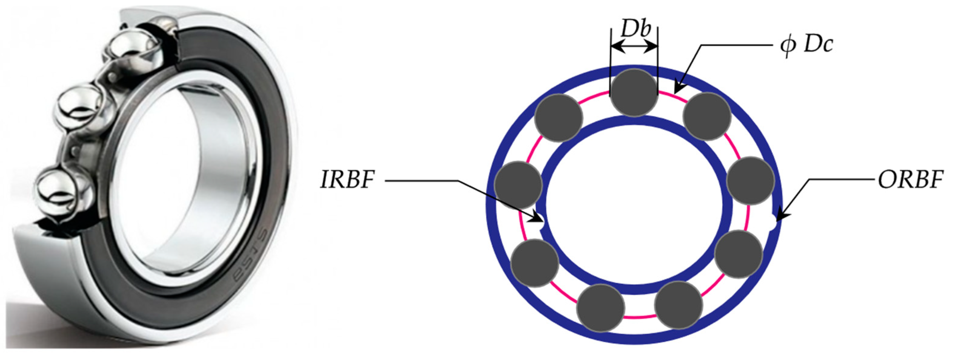
2.2. Bearing Defects
- BPFO: ball passage frequency on the outer ring for an ORBF.
- BPFI: ball passage frequency on the inner ring for an IRBF.
3. Hilbert’s Transform
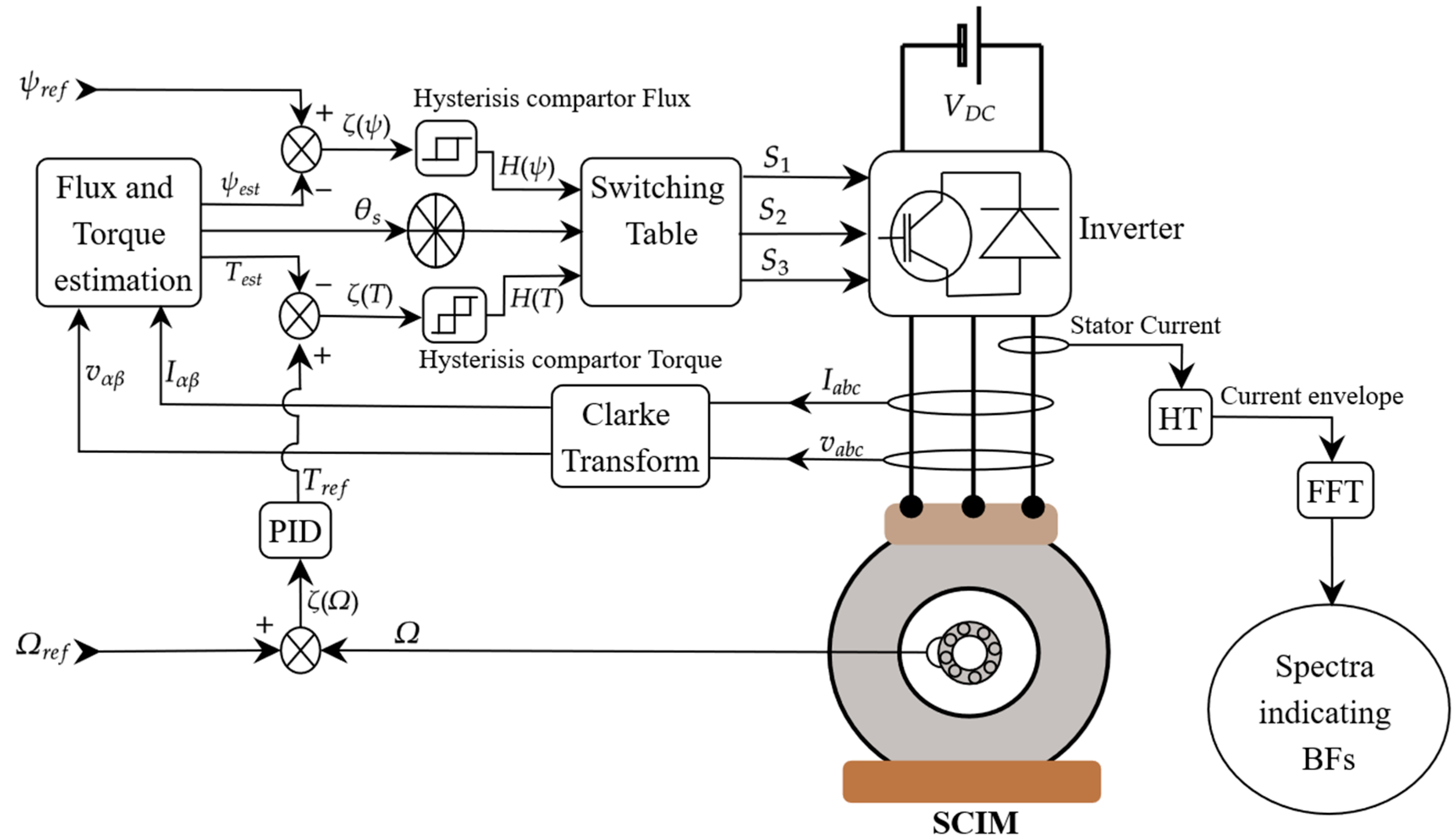
4. Direct Torque Control
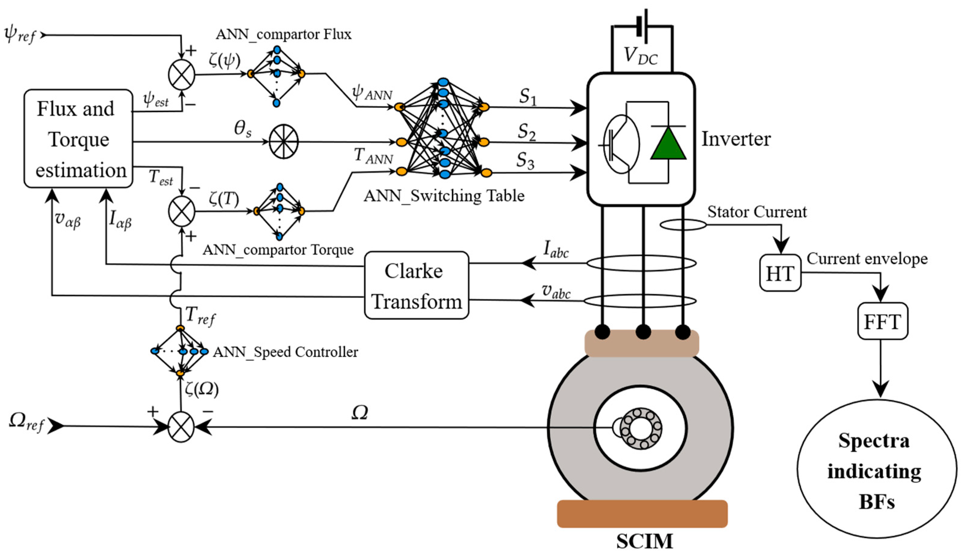
5. Direct Torque Control Based on Artificial Neural Networks
5.1. ANN-Based Comparators, Cruise Control, and Switchboard Controls
5.2. Values and the Algorithm Chosen for ANN
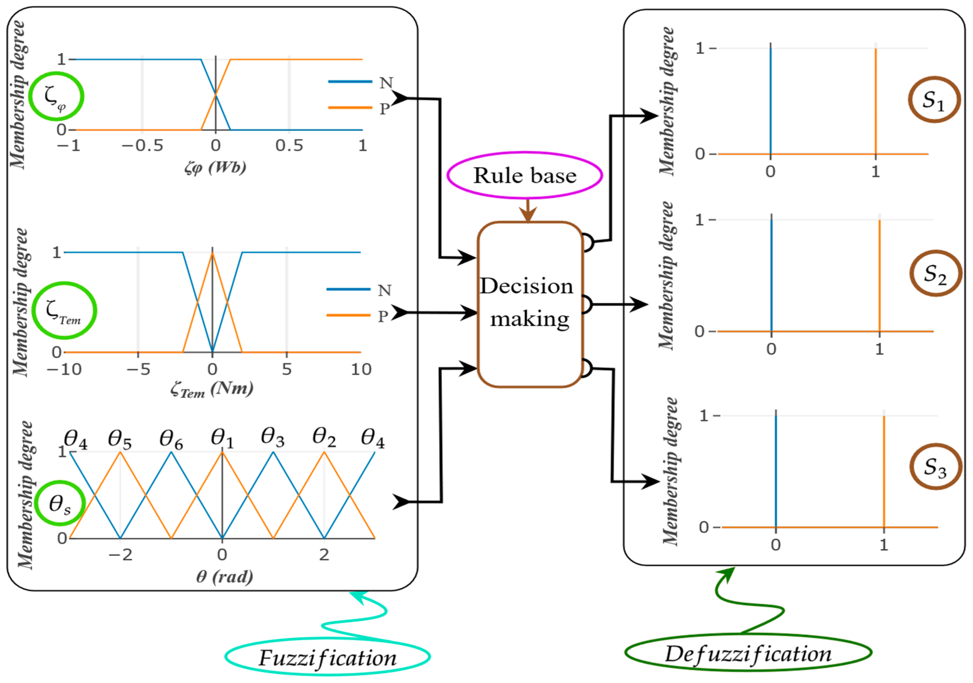
6. Direct Torque Control Based on Fuzzy Logic
7. Simulation Results and Discussions
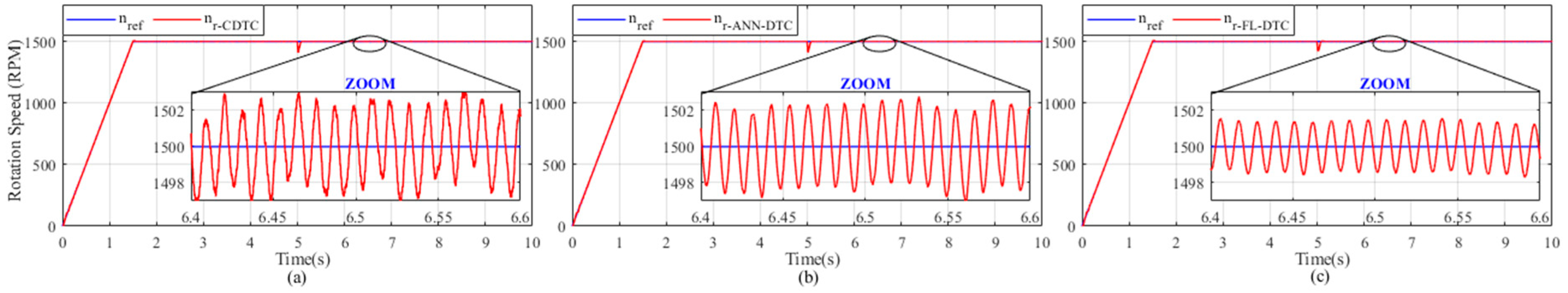
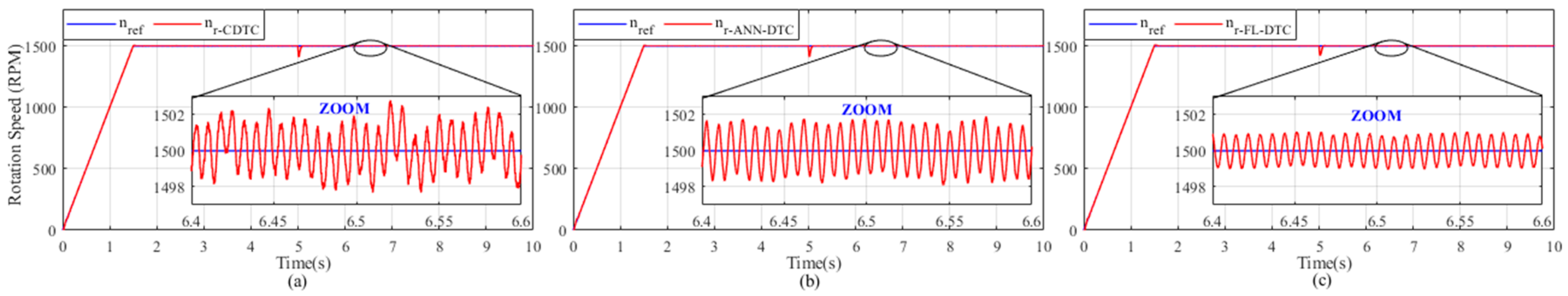
7.1. Rotational Speed
7.2. Electromagnetic Torque
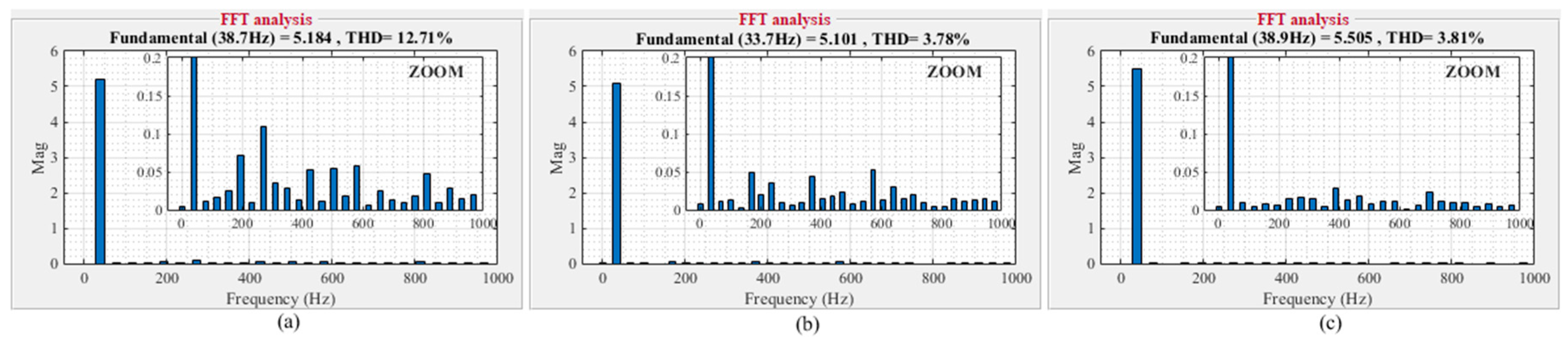
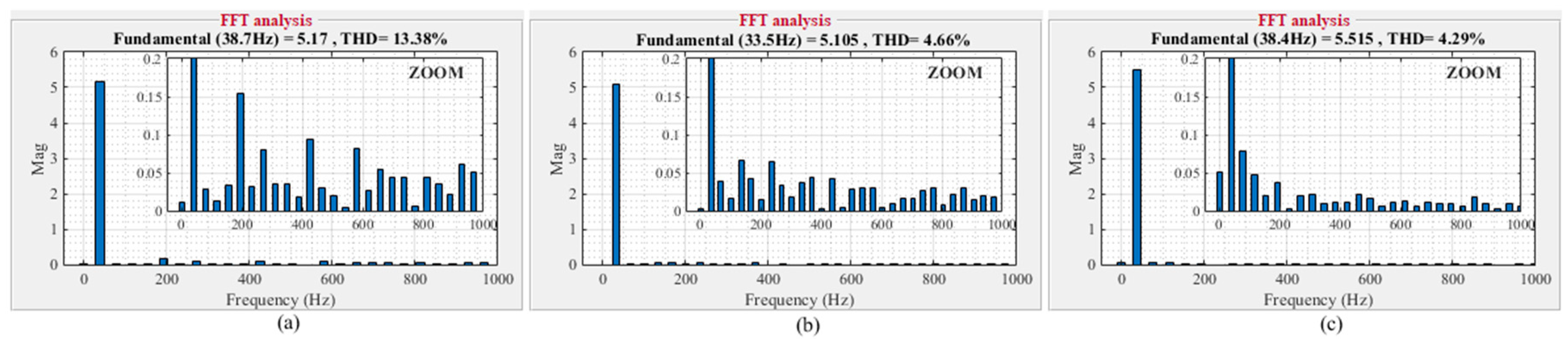
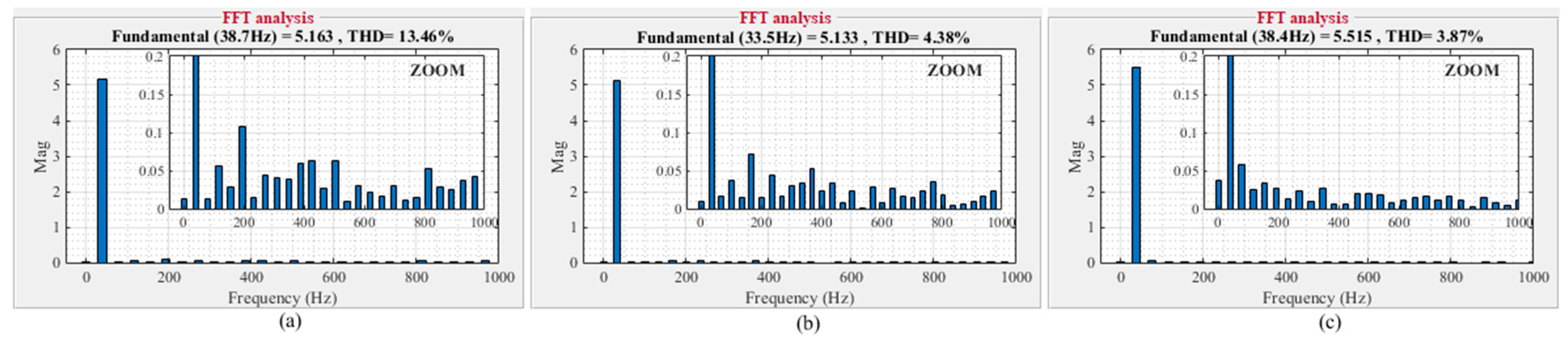
7.3. The Harmonic Distortion Rate (THD) of Stator Current
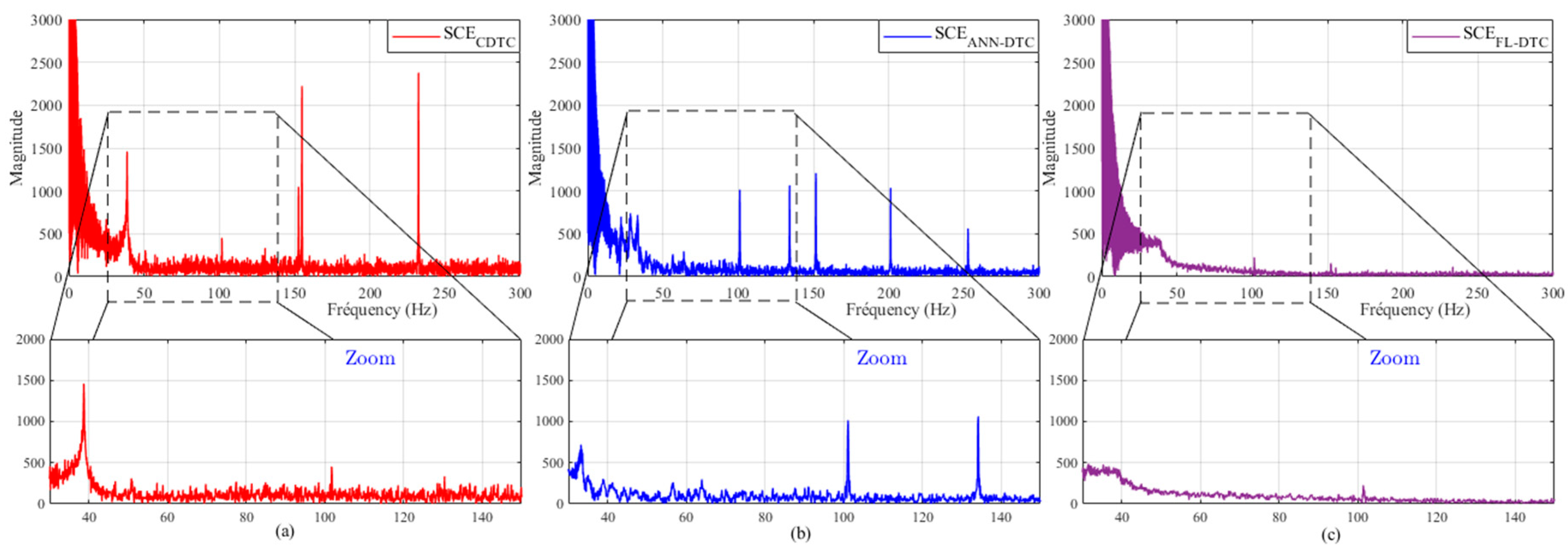
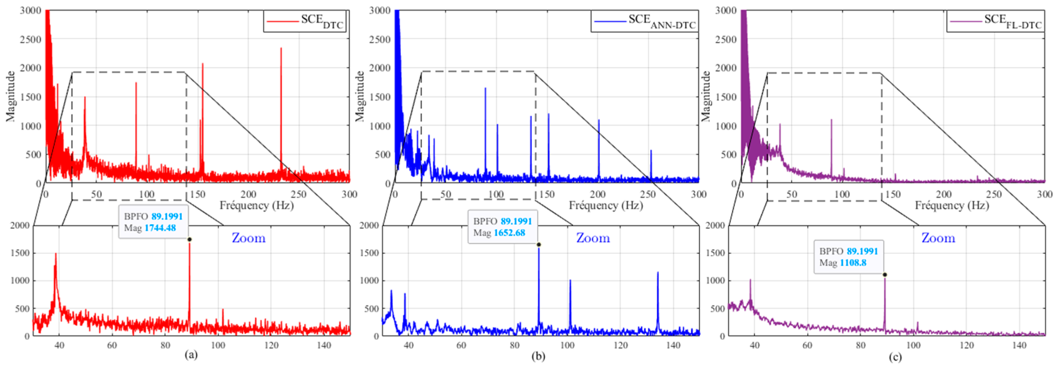
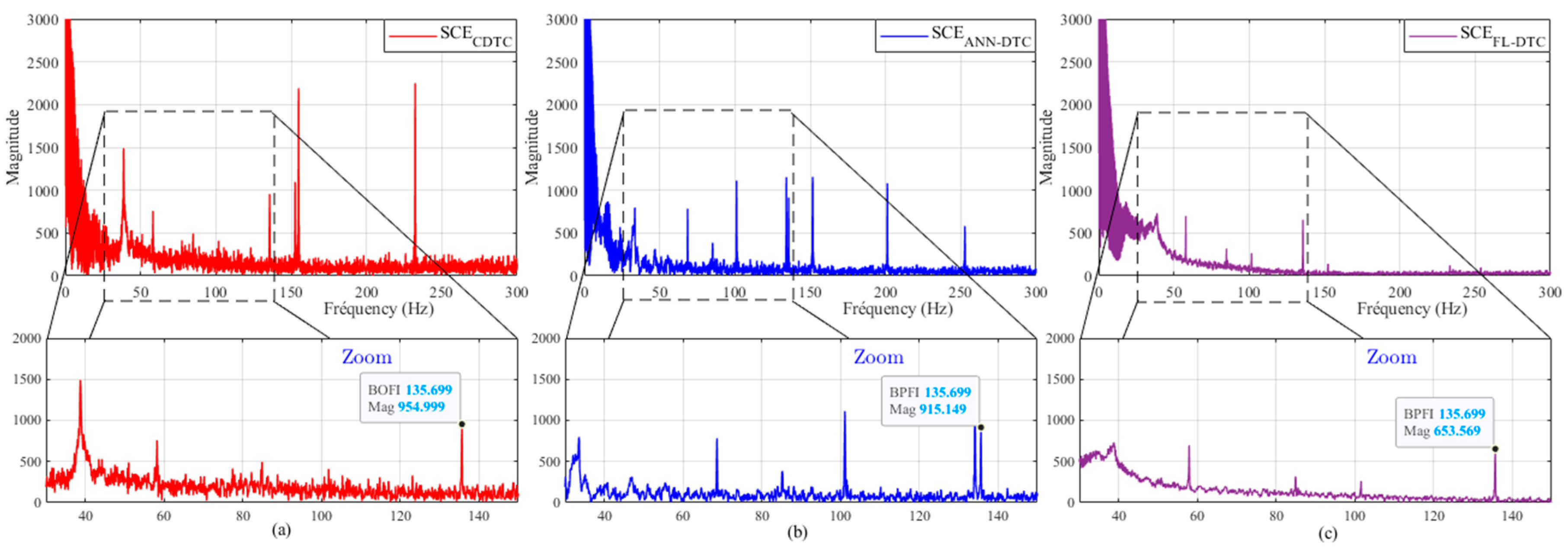
7.4. Envelope Current Spectrum (ECS)
8. Conclusions
Author Contributions
Funding
Institutional Review Board Statement
Informed Consent Statement
Data Availability Statement
Conflicts of Interest
Appendix A

| Variable | Value |
|---|---|
| Nominal power | Pu = 1.5 kW |
| Stator and rotor resistances | Rs = 4 Ω; Rr = 0. 8 Ω |
| Self-inductances | Ls = 0.39045 H |
| Rotor inductance | Lr = 0.02139 H |
| Maximum of mutual inductance | M = 0.08736 H |
| Viscous frictions | f = 0.004565 Kg·m2/s |
| Total inertia | J = 0.0147 Kg·m2 |
| Pair pole number | P = 2 |
| Type of Bearing | Inside Diameter | Outer Diameter | Width | Angle Contact α |
|---|---|---|---|---|
| 62052RSC3 | 25 mm | 52 mm | 15 mm | 0 |
| Number of Balls | Diameter of a Ball | Diameter of the Cage | Cosa |
|---|---|---|---|
| 9 | 7.94 mm | 38.5 mm | 1 |
| Parameters | Description |
|---|---|
| Vsα, Vsβ | Stator and rotor voltages in (α, β) plan |
| Isα, Isβ, Irα, and Irβ | Stator and rotor currents in (α, β) plan |
| Ψsα, Ψsβ, Ψrα, and Ψrβ | Stator and rotor fluxes in (α, β) plan |
| Rs, Rr | Stator and rotor resistors |
| Lf | Leakage inductance |
| Lm | Mutual Inductance |
| p | Number of pairs of poles |
| ωr | Rotor angular speed |
| ωs | Stator angular speed |
| ωm | Stator angular speed |
| Ω | Rotation speed |
| Tem | Electromagnetic torque |
| Tr | Resistant torque |
| f | Viscous friction coefficient |
| J | Moment of inertia |
| nr | Rotation speed (Rpm) |
| fr | Rotation frequency (Hz) |
References
- Song, X.; Hu, J.; Zhu, H.; Zhang, J. A bearing outer raceway fault detection method in induction motors based on instantaneous frequency of the stator current. IEEJ Trans. Electr. Electron. Eng. 2018, 13, 510–516. [Google Scholar] [CrossRef]
- El Idrissi, A.; Derouich, A.; Mahfoud, S.; El Ouanjli, N.; Chantoufi, A.; Al-Sumaiti, A.S.; Mossa, M.A. Bearing Fault Diagnosis for an Induction Motor Controlled by an Artificial Neural Network—Direct Torque Control Using the Hilbert Transform. Mathematics 2022, 10, 4258. [Google Scholar] [CrossRef]
- Atta, M.E.E.-D.; Ibrahim, D.K.; Gilany, M.I. Broken Bar Faults Detection Under Induction Motor Starting Conditions Using the Optimized Stockwell Transform and Adaptive Time–Frequency Filter. IEEE Trans. Instrum. Meas. 2021, 70, 3518110. [Google Scholar] [CrossRef]
- Ewert, P.; Kowalski, C.T.; Orlowska-Kowalska, T. Low-Cost Monitoring and Diagnosis System for Rolling Bearing Faults of the Induction Motor Based on Neural Network Approach. Electronics 2020, 9, 1334. [Google Scholar] [CrossRef]
- Puche-Panadero, R.; Martinez-Roman, J.; Sapena-Bano, A.; Burriel-Valencia, J.; Riera-Guasp, M. Fault Diagnosis in the Slip–Frequency Plane of Induction Machines Working in Time-Varying Conditions. Sensors 2020, 20, 3398. [Google Scholar] [CrossRef] [PubMed]
- Al-Yoonus, M.A.; Alyozbaky, O.S.A.-D. Detection of internal and external faults of single-phase induction motor using current signature. Int. J. Electr. Comput. Eng. (IJECE) 2021, 11, 2830–2841. [Google Scholar] [CrossRef]
- Laala, W.; Guedidi, A.; Guettaf, A. Bearing faults classification based on wavelet transform and artificial neural network. Int. J. Syst. Assur. Eng. Manag. 2020, 14, 37–44. [Google Scholar] [CrossRef]
- Blodt, M.; Granjon, P.; Raison, B.; Rostaing, G. Models for Bearing Damage Detection in Induction Motors Using Stator Current Monitoring. IEEE Trans. Ind. Electron. 2008, 55, 1813–1822. [Google Scholar] [CrossRef]
- Jafarian, M.J.; Nazarzadeh, J. Spectral analysis for diagnosis of bearing defects in induction machine drives. IET Electr. Power Appl. 2019, 13, 340–348. [Google Scholar] [CrossRef]
- Bouras, A.; Bennedjai, S.; Bouras, S. Experimental detection of defects in variable speed fan bearing using stator current monitoring. SN Appl. Sci. 2020, 2, 1–8. [Google Scholar] [CrossRef]
- Pilloni, A.; Pisano, A.; Riera-Guasp, M.; Puche-Panadero, R.; Pineda-Sanchez, M. Fault Detection in Induction Motors; Springer: Berlin/Heidelberg, Germany, 2013. [Google Scholar]
- Fourati, A.; Bourdon, A.; Rémond, D.; Feki, N.; Chaari, F.; Haddar, M. Current signal analysis of an induction machine with a defective rolling bearing. In Applied Condition Monitoring; Springer: Berlin/Heidelberg, Germany, 2018; Volume 9, pp. 45–54. [Google Scholar] [CrossRef]
- Mahfoud, S.; Derouich, A.; EL Ouanjli, N.; EL Mahfoud, M. Enhancement of the Direct Torque Control by using Artificial Neuron Network for a Doubly Fed Induction Motor. Intell. Syst. Appl. 2022, 13, 200060. [Google Scholar] [CrossRef]
- Bachiri, H.; Gasbaoui, B.; Ghezouani, A.; Nair, N. Improved direct torque control strategy performances of electric vehicles induction motor. Int. J. Power Electron. Drive Syst. (IJPEDS) 2022, 13, 716–723. [Google Scholar] [CrossRef]
- Benbouhenni, H. Seven-Level Direct Torque Control of Induction Motor Based on Artificial Neural Networks with Regulation Speed Using Fuzzy PI Controller. Iran. J. Electr. Electron. Eng. 2018, 14, 85–94. [Google Scholar]
- Ahmed, D.; Mokhtar, B.; Aek, B. DTC-ANN-2-level hybrid by neuronal hysteresis with mechanical sensorless induction motor drive using KUBOTA observer. Int. J. Power Electron. Drive Syst. (IJPEDS) 2020, 11, 34–44. [Google Scholar] [CrossRef]
- Mahfoud, S.; Derouich, A.; El Ouanjli, N.; El Idrissi, A.; El Mahfoud, M. Optimized PID Controller by Ant Colony Optimization of DTC for Doubly Fed Induction Motor. In Digital Technologies and Applications; ICDTA 2022. Lecture Notes in Networks and Systems; Motahhir, S., Bossoufi, B., Eds.; Springer: Cham, Switzerland, 2022; Volume 455. [Google Scholar] [CrossRef]
- Kumar, R.S.; Raj, I.G.C.; Suresh, K.P.; Leninpugalhanthi, P.; Suresh, M.; Panchal, H.; Meenakumari, R.; Sadasivuni, K.K. A method for broken bar fault diagnosis in three phase induction motor drive system using Artificial Neural Networks. Int. J. Ambient. Energy 2021, 43, 5138–5144. [Google Scholar] [CrossRef]
- Aissa, O.; Reffas, A.; Talhaoui, H.; Ziane, D.; Saim, A. An Improved Direct Torque Control with an Advanced Broken-Bar Fault Diagnosis for Induction Motor Drives. Int. Trans. Electr. Energy Syst. 2023, 2023, 8816896. [Google Scholar] [CrossRef]
- Ibrahim, S.O.; Faris, K.N.; Elzahab, E.A. Implementation of fuzzy modeling system for faults detection and diagnosis in three phase induction motor drive system. J. Electr. Syst. Inf. Technol. 2015, 2, 27–46. [Google Scholar] [CrossRef]
- Kumar, R.; Gupta, R.A.; Bhangale, S.V.; Gothwal, H. ANN based control and estimation of direct torque controlled induction motor drive. Asian Power Electron. J. 2008, 2, 115–122. [Google Scholar]
- Mohammed, H.; Meroufel, A. Contribution to the Neural network speed estimator for sensor-less fuzzy direct control of torque application using double stars induction machine. In Proceedings of the 2014 International Conference on Electrical Sciences and Technologies in Maghreb (CISTEM), Tunis, Tunisia, 3–6 November 2014; Volume 5. [Google Scholar] [CrossRef]
- El Daoudi, S.; Lazrak, L.; El Ouanjli, N.; Lafkih, M.A. Sensorless fuzzy direct torque control of induction motor with sliding mode speed controller. Comput. Electr. Eng. 2021, 96, 107490. [Google Scholar] [CrossRef]
- El Ouanjli, N.; Motahhir, S.; Derouich, A.; El Ghzizal, A.; Chebabhi, A.; Taoussi, M. Improved DTC strategy of doubly fed induction motor using fuzzy logic controller. Energy Rep. 2019, 5, 271–279. [Google Scholar] [CrossRef]
- Banu, J.B.; Jeyashanthi, J.; Ansari, A.T. DTC-IM drive using adaptive neuro fuzzy inference strategy with multilevel inverter. J. Ambient. Intell. Humaniz. Comput. 2022, 13, 4799–4821. [Google Scholar] [CrossRef]
- Basappa, M.H.; Viswanathan, P. ANFIS based Direct Torque Control of PMSM Motor for Speed and Torque Regulation. Indones. J. Electr. Eng. Inform. (IJEEI) 2022, 10, 549–558. [Google Scholar] [CrossRef]
- Ramu, S.K.; Irudayaraj, G.C.R.; Subramani, S.; Subramaniam, U. Broken rotor bar fault detection using Hilbert transform and neural networks applied to direct torque control of induction motor drive. IET Power Electron. 2020, 13, 3328–3338. [Google Scholar] [CrossRef]
- Mejia-Barron, A.; Tapia-Tinoco, G.; Razo-Hernandez, J.R.; Valtierra-Rodriguez, M.; Granados-Lieberman, D. A neural network-based model for MCSA of inter-turn short-circuit faults in induction motors and its power hardware in the loop simulation. Comput. Electr. Eng. 2021, 93, 107234. [Google Scholar] [CrossRef]
- Valtierra-Rodriguez, M.; Rivera-Guillen, J.R.; Basurto-Hurtado, J.A.; De-Santiago-Perez, J.J.; Granados-Lieberman, D.; Amezquita-Sanchez, J.P. Convolutional Neural Network and Motor Current Signature Analysis during the Transient State for Detection of Broken Rotor Bars in Induction Motors. Sensors 2020, 20, 3721. [Google Scholar] [CrossRef] [PubMed]
- Hosseini, E.; Mirzaei, A. An Improved Method for Diagnosis of Induction Motor Load Mechanical Unbalance Fault Using Current Signal Analysis. Russ. Electr. Eng. 2020, 91, 217–224. [Google Scholar] [CrossRef]
- Wang, B.; Zhou, L.; Miyoshi, M.; Inoue, H.; Kanemaru, M. Quantification of Induction Motor Bearing Fault Severity based on Modified Winding Function Theory. In Proceedings of the 24th International Conference on Electrical Machines and Systems (ICEMS), Gyeongju, Republic of Korea, 31 October–3 November 2021. [Google Scholar]
- Wang, Z.; Shi, D.; Xu, Y.; Zhen, D.; Gu, F.; Ball, A.D. Early rolling bearing fault diagnosis in induction motors based on on-rotor sensing vibrations. Measurement 2023, 222, 113614. [Google Scholar] [CrossRef]
- Asad, B.; Vaimann, T.; Belahcen, A.; Kallaste, A.; Rassõlkin, A.; Iqbal, M.N. Broken rotor bar fault detection of the grid and inverter-fed induction motor by effective attenuation of the fundamental component. IET Electr. Power Appl. 2019, 13, 2005–2014. [Google Scholar] [CrossRef]
- Toma, R.N.; Kim, J.-M. Bearing Fault Classification of Induction Motors Using Discrete Wavelet Transform and Ensemble Machine Learning Algorithms. Appl. Sci. 2020, 10, 5251. [Google Scholar] [CrossRef]
- Zimnickas, T.; Vanagas, J.; Dambrauskas, K.; Kalvaitis, A. A Technique for Frequency Converter-Fed Asynchronous Motor Vibration Monitoring and Fault Classification, Applying Continuous Wavelet Transform and Convolutional Neural Networks. Energies 2020, 13, 3690. [Google Scholar] [CrossRef]
- Feldman, M. Hilbert transform in vibration analysis. Mech. Syst. Signal Process. 2011, 25, 735–802. [Google Scholar] [CrossRef]
- Poddar, S.; Chandravanshi, M.L. Ball Bearing Fault Detection Using Vibration Parameters. Int. J. Eng. Res. Technol. (IJERT) 2013, 2, 1239–1244. [Google Scholar]
- Awada, E.; Al-Qaisi, A.; Radwan, E.; Nour, M. Motor fault detection using sound signature and wavelet transform. Int. J. Power Electron. Drive Syst. (IJPEDS) 2022, 13, 247–255. [Google Scholar] [CrossRef]
- Delgado-Arredondo, P.A.; Morinigo-Sotelo, D.; Osornio-Rios, R.A.; Avina-Cervantes, J.G.; Rostro-Gonzalez, H.; Romero-Troncoso, R.D.J. Methodology for fault detection in induction motors via sound and vibration signals. Mech. Syst. Signal Process. 2017, 83, 568–589. [Google Scholar] [CrossRef]
- AlShorman, O.; Alkahatni, F.; Masadeh, M.; Irfan, M.; Glowacz, A.; Althobiani, F.; Kozik, J.; Glowacz, W. Sounds and acoustic emission-based early fault diagnosis of induction motor: A review study. Adv. Mech. Eng. 2021, 13, 1687814021996915. [Google Scholar] [CrossRef]
- Choudhary, A.; Goyal, D.; Letha, S.S. Infrared Thermography-Based Fault Diagnosis of Induction Motor Bearings Using Machine Learning. IEEE Sens. J. 2021, 21, 1727–1734. [Google Scholar] [CrossRef]
- Lim, G.-M.; Bae, D.-M.; Kim, J.-H. Fault diagnosis of rotating machine by thermography method on support vector machine. J. Mech. Sci. Technol. 2014, 28, 2947–2952. [Google Scholar] [CrossRef]
- Choudhary, A.; Shimi, S.; Akula, A. Bearing fault diagnosis of induction motor using thermal imaging. In Proceedings of the 2018 International Conference on Computing, Power and Communication Technologies (GUCON), Greater Noida, India, 28–29 September 2018; pp. 950–955. [Google Scholar] [CrossRef]
- Alhammad, M.; Avdelidis, N.P.; Ibarra-Castanedo, C.; Torbali, M.E.; Genest, M.; Zhang, H.; Zolotas, A.; Maldgue, X.P.V. Automated Impact Damage Detection Technique for Composites Based on Thermographic Image Processing and Machine Learning Classification. Sensors 2022, 22, 9031. [Google Scholar] [CrossRef] [PubMed]
- Picazo-Ródenas, M.; Royo, R.; Antonino-Daviu, J.; Roger-Folch, J. Use of the infrared data for heating curve computation in induction motors: Application to fault diagnosis. Eng. Fail. Anal. 2013, 35, 178–192. [Google Scholar] [CrossRef]
- Duque-Perez, O.; Del Pozo-Gallego, C.; Morinigo-Sotelo, D.; Godoy, W.F. Condition Monitoring of Bearing Faults Using the Stator Current and Shrinkage Methods. Energies 2019, 12, 3392. [Google Scholar] [CrossRef]
- Lin, H.; Lin, C.; Xie, D.; Acuna, P.; Liu, W. A Counter-Based Open-Circuit Switch Fault Diagnostic Method for a Single-Phase Cascaded H-Bridge Multilevel Converter. IEEE Trans. Power Electron. 2024, 39, 814–825. [Google Scholar] [CrossRef]
- Cheng, C.; Li, X.; Xie, P.; Yang, X. Transfer-Learning-Aided Fault Detection for Traction Drive Systems of High-Speed Trains. IEEE Trans. Artif. Intell. 2023, 4, 689–697. [Google Scholar] [CrossRef]
- Espinoza-Trejo, D.R.; Castro, L.M.; Bárcenas, E.; Sánchez, J.P. Data-Driven Switch Fault Diagnosis for DC/DC Boost Converters in Photovoltaic Applications. IEEE Trans. Ind. Electron. 2023, 71, 1631–1640. [Google Scholar] [CrossRef]
- Asad, B.; Vaimann, T.; Belahcen, A.; Kallaste, A.; Rassõlkin, A.; Ghafarokhi, P.S.; Kudelina, K. Transient Modeling and Recovery of Non-Stationary Fault Signature for Condition Monitoring of Induction Motors. Appl. Sci. 2021, 11, 2806. [Google Scholar] [CrossRef]
- El Idrissi, A.; Derouich, A.; Mahfoud, S.; El Ouanjli, N.; Chantoufi, A. Bearing ball fault diagnosis of an induction machine by using the Hilbert transform and the performance of intelligent control. In Reading Notes in Networks and Systems; Springer: Berlin, Germany, 2023; pp. 580–589. [Google Scholar] [CrossRef]
- Nakamura, H.; Mizuno, Y. Diagnosis for Slight Bearing Fault in Induction Motor Based on Combination of Selective Features and Machine Learning. Energies 2022, 15, 453. [Google Scholar] [CrossRef]
- Belkacemi, B.; Saad, S. Inner and Outer Race Bearing Defects of Induction Motor Running at Low Speeds Signal Analysis with DWT. In Advances in Intelligent Systems and Computing; Springer: Berlin/Heidelberg, Germany, 2021; Volume 1383, pp. 975–983. [Google Scholar] [CrossRef]
- Konar, P.; Chattopadhyay, P. Multi-class fault diagnosis of induction motor using Hilbert and Wavelet Transform. Appl. Soft Comput. 2015, 30, 341–352. [Google Scholar] [CrossRef]
- Dehina, W.; Boumehraz, M.; Kratz, F. Diagnosis and Detection of Rotor Bars Faults in Induction Motor Using HT and DWT Techniques. In Proceedings of the 2021 18th International Multi-Conference on Systems, Signals & Devices (SSD), Monastir, Tunisia, 22–25 March 2021; pp. 109–115. [Google Scholar]
- Sinha, A.K.; Hati, A.S.; Benbouzid, M.; Chakrabarti, P. ANN-Based Pattern Recognition for Induction Motor Broken Rotor Bar Monitoring under Supply Frequency Regulation. Machines 2021, 9, 87. [Google Scholar] [CrossRef]
- El Idrissi, A.; Derouich, A.; Mahfoud, S. Fault Diagnosis of the Bearing Outer Ring of an Induction Motor Under DTC Control by Using Hilbert Filter. In Digital Technologies and Applications; Springer: Cham, Switzerland, 2022; Volume 454. [Google Scholar] [CrossRef]
- Elbouchikhi, E.; Choqueuse, V.; Benbouzid, M. Induction machine bearing faults detection based on a multi-dimensional MUSIC algorithm and maximum likelihood estimation. ISA Trans. 2016, 63, 413–424. [Google Scholar] [CrossRef] [PubMed]
- Bazan, G.H.; Goedtel, A.; Duque-Perez, O.; Morinigo-Sotelo, D. Multi-Fault Diagnosis in Three-Phase Induction Motors Using Data Optimization and Machine Learning Techniques. Electronics 2021, 10, 1462. [Google Scholar] [CrossRef]
- Zhang, S.; Wang, B.; Kanemaru, M.; Lin, C.; Liu, D.; Miyoshi, M.; Teo, K.H.; Habetler, T.G. Model-Based Analysis and Quantification of Bearing Faults in Induction Machines. IEEE Trans. Ind. Appl. 2020, 56, 2158–2170. [Google Scholar] [CrossRef]
- Abd-El-Malek, M.B.; Abdelsalam, A.K.; Hassan, O.E. Novel approach using Hilbert Transform for multiple broken rotor bars fault location detection for three phase induction motor. ISA Trans. 2018, 80, 439–457. [Google Scholar] [CrossRef] [PubMed]
- Liu, Z.; Peng, D.; Zuo, M.J.; Xia, J.; Qin, Y. Improved Hilbert–Huang transform with soft sifting stopping criterion and its application to fault diagnosis of wheelset bearings. ISA Trans. 2021, 125, 426–444. [Google Scholar] [CrossRef] [PubMed]
- Orosz, T.; Rassõlkin, A.; Kallaste, A.; Arsénio, P.; Pánek, D.; Kaska, J.; Karban, P. Robust Design Optimization and Emerging Technologies for Electrical Machines: Challenges and Open Problems. Appl. Sci. 2020, 10, 6653. [Google Scholar] [CrossRef]
- El Ouanjli, N.; Taoussi, M.; Derouich, A.; Chebabhi, A.; El Ghzizal, A.; Bossoufi, B. High performance direct torque control of doubly fed induction motor using fuzzy logic. Gazi Univ. J. Sci. 2018, 31, 532–542. [Google Scholar]


| Flux Variation H(ψs) | Torque Variations H(Tem) | Sectors Si | |||||
|---|---|---|---|---|---|---|---|
| S1 | S2 | S3 | S4 | S5 | S6 | ||
| Δψs = 1 | ΔTem = 1 | V2 | V3 | V4 | V5 | V6 | V1 |
| ΔTem = 0 | V7 | V0 | V7 | V0 | V7 | V0 | |
| ΔTem = −1 | V6 | V1 | V2 | V3 | V4 | V5 | |
| Δψs = 0 | ΔTem = 1 | V3 | V4 | V5 | V6 | V1 | V2 |
| ΔTem = 0 | V0 | V7 | V0 | V7 | V0 | V7 | |
| ΔTem = −1 | V5 | V6 | V1 | V2 | V3 | V4 | |
| Learning Outcomes | Values | |||
|---|---|---|---|---|
| ANN_Ω | ANN_T | ANN_ψ | ANN_SW_T | |
| Number of iterations | 1000 | 85 | 209 | 168 |
| Time | 0:00:34 | 0:00:21 | 0:00:34 | 0:00:34 |
| Performance | 0.000538 | 0.0148 | 0.000506 | 0.000459 |
| Gradient | 4.04 | 2.09 × 10⁻⁵ | 7.31 × 10⁻⁶ | 1.18 × 10⁻⁵ |
| Him | 0.01 | 10−9 | 10−9 | 10−5 |
| Validation checks | 0 | 6 | 6 | 6 |
| Best validation performance | 7.5373 × 10⁻⁴ at epoch 1000 | 1.2627 × 10⁻³ at epoch 79 | 5.4767 × 10⁻³ at epoch 203 | 3.9404 × 10⁻⁴ at epoch 162 |
| ANN Parameters | Values | |||
|---|---|---|---|---|
| ANN_Ω | ANN_T | ANN_ψ | ANN_SW_T | |
| Neural network | Three-layer feed-forward network with sigmoid hidden neurons | |||
| Number of hidden layer nodes | 10 | 10 | 10 | 10 |
| Number of neurons in the input layer | 1 | 1 | 1 | 3 |
| Number of neurons in the second hidden layer | 1 | 1 | 1 | 3 |
| Number of neurons in the output layer | 1 | 1 | 1 | 3 |
| Learning rate | 0.5 | 0.5 | 0.5 | 0.5 |
| Number of epochs | 20 | 100 | 100 | 200 |
| ζψ | ζTem | i1 | i2 | i3 | i4 | i5 | i6 |
|---|---|---|---|---|---|---|---|
| P | N | V6 (101) | V1 (100) | V2 (110) | V3 (010) | V4 (011) | V5 (001) |
| P | Z | V7 (111) | V0 (000) | V7 (111) | V0 (000) | V7 (111) | V0 (000) |
| P | P | V2 (110) | V3 (010) | V4 (011) | V5 (001) | V6 (101) | V1 (100) |
| N | N | V5 (001) | V6 (101) | V1 (100) | V2 (110) | V3 (010) | V4 (011) |
| N | Z | V0 (000) | V7 (111) | V0 (000) | V7 (111) | V0 (000) | V7 (111) |
| N | P | V3 (010) | V4 (011) | V5 (001) | V6 (101) | V1 (100) | V2 (110) |
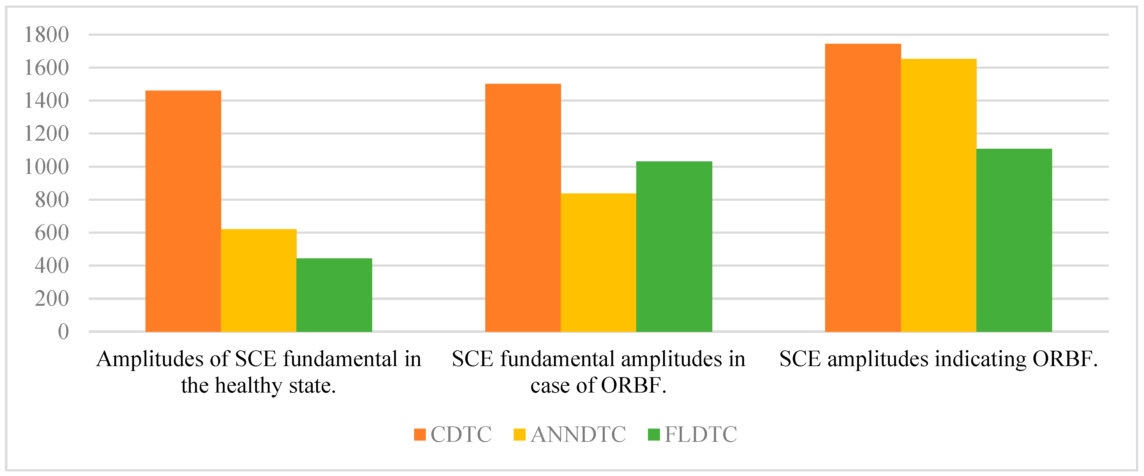
| Nature of DTC | Amplitudes from the Fundamental to the Healthy State | Amplitudes of the Fundamental in the Presence of ORBF | Amplitudes SCE de ORBF | ORBF Report | Number of Spectra in the Range 0 to 150 Hz in the Healthy State |
|---|---|---|---|---|---|
| CDTC | 1461 | 1502 | 1744 | 1.16 | 4 |
| ANNDTC | 621 | 837 | 1652 | 1.97 | 5 |
| FLDTC | 443 | 1031 | 1108 | 1.07 | 3 |
| Nature of DTC | Amplitudes from the Fundamental to the Healthy State | Amplitudes of the Fundamental in the Presence of IRBF | Amplitudes SCE de IRBF | IRBF Report | Number of Spectra in the Range 0 to 150 Hz in the Healthy State |
|---|---|---|---|---|---|
| CDTC | 1461 | 1493 | 955 | 0.64 | 4 |
| ANNDTC | 621 | 796 | 915 | 1.15 | 5 |
| FLDTC | 443 | 732 | 653 | 0.9 | 3 |
| Publication Reference | Control Type | Signal Processing Tool | Faults | Is the Control Helping to Diagnose (Yes/No)? |
|---|---|---|---|---|
| [2] | ANN-DTC | HT | BFs | Yes |
| [18] | CDTC | HT | BRB | No |
| [19] | ANN-FL-DTC | HT-DWT-ANNs | BRB | Yes |
| [61] | Variable frequency drives | HT | BRB | No |
| Proposed technique | ANN-DTC/FL-DTC | HT | BFs | Yes |
Disclaimer/Publisher’s Note: The statements, opinions and data contained in all publications are solely those of the individual author(s) and contributor(s) and not of MDPI and/or the editor(s). MDPI and/or the editor(s) disclaim responsibility for any injury to people or property resulting from any ideas, methods, instructions or products referred to in the content. |
© 2024 by the authors. Licensee MDPI, Basel, Switzerland. This article is an open access article distributed under the terms and conditions of the Creative Commons Attribution (CC BY) license (https://creativecommons.org/licenses/by/4.0/).
Share and Cite
El Idrissi, A.; Derouich, A.; Mahfoud, S.; El Ouanjli, N.; Chojaa, H.; Chantoufi, A. Bearing Faults Diagnosis by Current Envelope Analysis under Direct Torque Control Based on Neural Networks and Fuzzy Logic—A Comparative Study. Electronics 2024, 13, 3195. https://doi.org/10.3390/electronics13163195
El Idrissi A, Derouich A, Mahfoud S, El Ouanjli N, Chojaa H, Chantoufi A. Bearing Faults Diagnosis by Current Envelope Analysis under Direct Torque Control Based on Neural Networks and Fuzzy Logic—A Comparative Study. Electronics. 2024; 13(16):3195. https://doi.org/10.3390/electronics13163195
Chicago/Turabian StyleEl Idrissi, Abderrahman, Aziz Derouich, Said Mahfoud, Najib El Ouanjli, Hamid Chojaa, and Ahmed Chantoufi. 2024. "Bearing Faults Diagnosis by Current Envelope Analysis under Direct Torque Control Based on Neural Networks and Fuzzy Logic—A Comparative Study" Electronics 13, no. 16: 3195. https://doi.org/10.3390/electronics13163195