Article

A Compact MIMO Rectangular Dielectric Resonator Antenna for Millimeter-Wave Communication

1
Communications Research Group, Department of Electronic and Electrical Engineering, The University of Sheffield, Sheffield S1 3JD, UK
2
National Physical Laboratory (NPL), Electromagnetic and Electrochemical Technologies Department, Teddington TW11 0LW, UK
*
Author to whom correspondence should be addressed.
Electronics 2024, 13(16), 3280; https://doi.org/10.3390/electronics13163280
Submission received: 5 July 2024 / Revised: 14 August 2024 / Accepted: 15 August 2024 / Published: 19 August 2024
(This article belongs to the Special Issue 5G Mobile Telecommunication Systems and Recent Advances)

Abstract

:
A Rectangular Dielectric Resonator Antenna (RDRA) design for mmWave-frequency-band MIMO metrics is proposed, with a compact, low-complexity, high-gain structure that is easy to fabricate and offers reduced inter–port isolation. The RDRA operates in the mmWave spectrum, featuring a compact size of 1.307 λ 0 × 1.307 λ 0 , an impedance bandwidth of 6%, and a resonant frequency of 28 GHz, with a peak gain of 7 dBi. A four element MIMO system iteration was developed while maintaining the performance of the single element antenna. Additionally, a simple, low-complexity slot-etching technique was applied to achieve an average inter-port element isolation of 14 dB. The design also achieved a novel four-beam petal-splitting radiation pattern. The MIMO metrics, with an envelope correlation coefficient (ECC) of <0.5 and a diversity gain (DG) < 10, were successfully met. The simulated and measured results are in good agreement.

1. Introduction

The fifth generation emerged to address user growth necessities and achieve a solid communications infrastructure that maintains accessibility, availability, and high user demand. The eight key principles of 5G communications are latency, mobility, spectrum, user-experienced data rate, peak data rate, area traffic capacity, network energy efficiency, and connection density [1]. In 5G communications, MIMO is a fundamental technology for achieving high data rates with improved signal quality in a context where some of the main customer applications are, e.g., user-centric computing, smart transportation, multimedia streaming, and telemedicine. Dielectric resonator antennas (DRAs) are potential candidates for channel-stage conforming MIMO systems, having promising attributes, including design simplicity and ease of fabrication, resulting in higher gain values than other antenna types, such as microstrip antennas. The literature presents some cases of MIMO DRA designs at mmWave consisting of a four-MIMO hemispherical dielectric resonator antenna (HDRA) element design, remarking the use of graphene strips and a maximum gain of 7 dBi with an individual radiation pattern analysis [2]. In [3], a four element MIMO cylindrical dielectric resonator (CDRA) with a maximum 10 dBi gain and a summing network for each of four resonators is presented. Additional fabrication and design challenges can be added to both designs, which have relatively similar results compared to simpler designs with rectangular radiators. Setting the scene at the communications channel stage, RDRA’s are a potential technology being investigated in architectures such as multiple input multiple output (MIMO) to fulfill the generation demands.
In the literature, two-port RDRA MIMO designs in the mmWave region are presented, proposing individual port testing excitation [4,5,6,7,8] and a gain ranging from 6.4 to 11 dBi. In [4,6], the proposed design demonstrates an inter-port isolation of 20 dB. A 30 dB isolation is reported in [7], with the addition of vias inside the two-element RDRAs. The most utilized isolating techniques are based on the antenna location, antenna spacing between components, the addition of etched meandered-line complex patterns, metal strips on the DR top surface, and the use of summing independent networks, with the maximum isolation reported being 20 dB considering a reflection coefficient value less than −20 dB. Moreover, complex designs present an increase in gain given only by the nature of the resonant frequency when sacrificing isolating elements [9,10]. Furthermore, there is a prevalence of publications studying systems with individual antenna excitation ports.
Four port MIMO RDRA designs have been reported with gains in the range of 7 dBi to 9.9 dBi and having overall sizes of 20 × 40 mm [9] and of 15.84 × 5 mm [11]. The first four element MIMO design demonstrated an inter-port isolation of 22 dB, attributed to the discontinuity of the Ground Plane (GP). The second case demonstrated an inter-port isolation of 15.2 dB due to the addition of metamaterials on top of the RDR. A a 4 MIMO RDRA element with a peak gain of 4.2 dBi, a maximum reduction of 40 dB and an efficiency of 86% was reported in [12].
A metamaterial placed between two RDRAs, achieving a reduction of 30 dB, was reported in [13], with 28 dB in [14,15]. Individual antenna excitation port radiation patterns with load termination were presented for both cases. There are a limited amount of studies regarding compact, simultaneous antenna system excitation and inter-element isolation techniques at the mmWave in RDRAs in the MIMO literature.
The present work proposes compact, low-complexity, high-gain, easy to fabricate, and reduced inter-port isolation RDRA designs for the mmWave frequency band complying with the MIMO ECC and DG metrics. A single antenna element was first designed followed by a four element MIMO with four-beam radiation, tested simultaneously with a power splitter such that the beam splitter petals could be ideally identified. Furthermore, the MIMO design proposes a simple mutual coupling reduction method using a slot-etching technique with a shared GP. A four element RDRA with simultaneous multi-beam radiation has not been reported in the literature before. The proposed solution is suitable for multi-user MIMO systems owing to the multi-beam radiation achieved by utilizing staggered elements, compared to the existing constructions that offer single-beam MIMO configurations.

2. Antenna Configuration

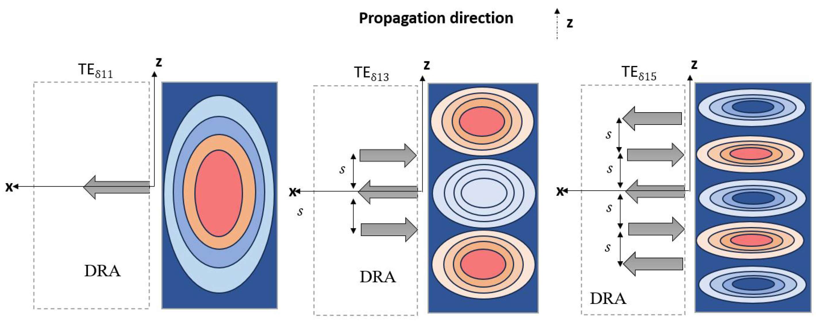
2.1. Rectangular Dielectric Resonator Antennas

DRAs were theoretically demonstrated by R.D. Richtmyer in 1939 [16] and incorporated as a fundamental part of a novel antenna design in 1983 [17]. They are considered potential solutions for enhancing antenna characteristics due to their capability for delivering wide bandwidths and high radiation efficiencies, and are fabricated with low-power-loss ceramic materials. However, they have some drawbacks, such as the need for precise alignment and relatively low bandwidths, which can impact the antenna performance depending on the operating frequency band. Some common examples of resonator shapes are cylindrical, rectangular, triangular, spherical, and hemispherical. For this particular case, a rectangular radiator was utilized due to its simplicity of design and ease and precision of fabrication. It was also considered due to the feasibility of manually aligning it with a reduced size. Slot aperture feeding is preferred at mmWave due to its reduced conductor and dielectric losses, radiation characteristics with less spurious radiation, as well as improved heat dissipation, compared, for example, with a microstrip feeding line.
A typical RDR structure consists of a base with dimensions w, h, and a height l. DRA modes are defined as the theoretical expressions for the electromagnetic fields inside the DRA; they can be classified as transverse electric (TE), transverse magnetic (TM), and transverse electromagnetic (TEM). Once the RDRA is excited, the magnetic field experiences constructive or destructive interference depending on the ceramic material characteristics, e.g., size and permittivity. The resonator generates TE modes, denoted as m and n, which are defined by the number of short magnetic dipoles generated inside the resonator and propagated on each x, y, z plane. According to [18], there is an increase in gain for higher-order modes and a bandwidth reduction due to the increase in the TE mode’s order. Figure 1 illustrates short magnetic dipole propagation in the z direction.
A dielectric wave model (DWM) [19] mathematically models the magnetic field extrema inside the RDRA. The wavenumber equations of the coordinate system through the RDRA are expressed as below:
k x 2 + k y 2 + k z 2 = ϵ r k 0 2
After considering the resonant frequency of the antenna,
k 0 = 2 π λ 0 = 2 π f 0 c
where k 0 refers to the free-space wavenumber. After substituting Equation (1) into (2),
f 0 = c 2 π ϵ r k x 2 + k y 2 + k z 2
In Equation (3), c represents the speed of light 3 × 10 8 m s , λ 0 refers to the free-space wavelength, and ϵ r is the relative permittivity of the dielectric.

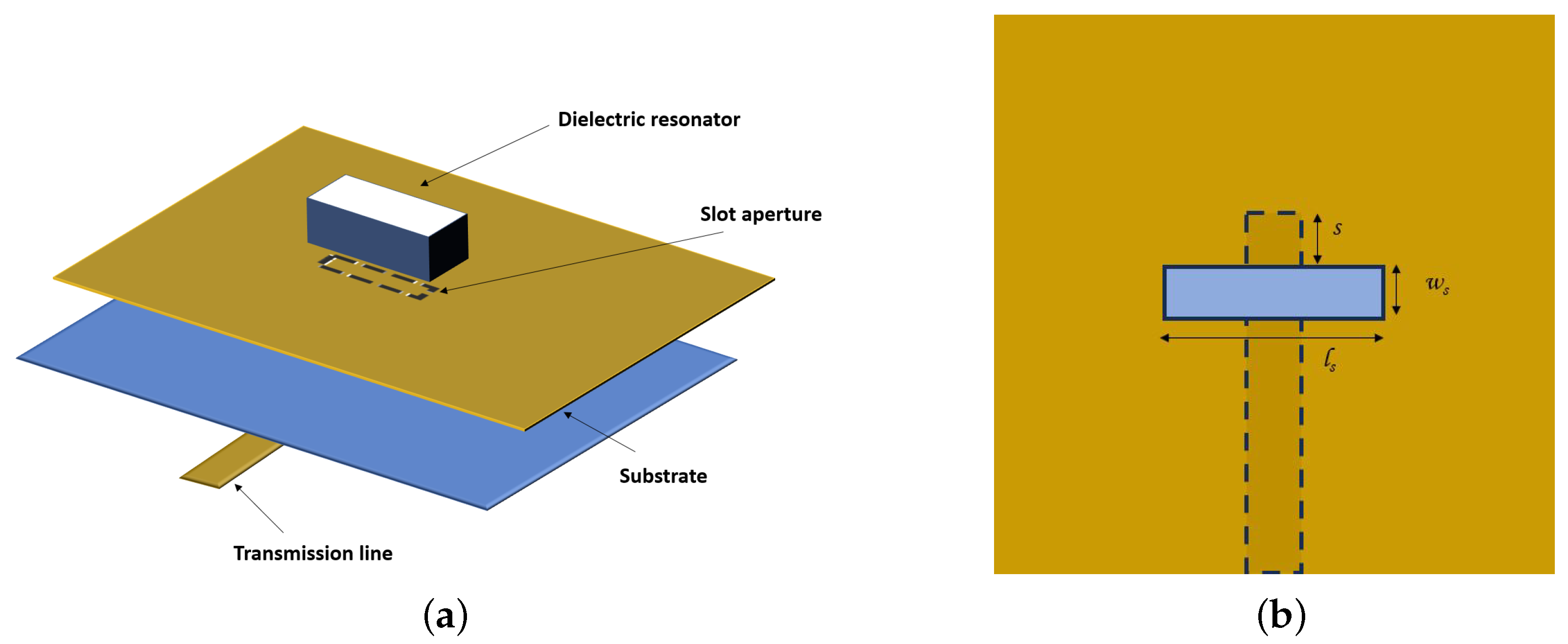
2.2. Slot Aperture RDRA Feeding Mechanism

Some examples of the existing DRA feeding mechanisms in the literature refer to coaxial probe-fed [20], aperture coupled-fed [21], microstrip feedline [22], co-planar waveguide-fed [23], and conformal stripline [24]. At mmWave frequencies, a slot aperture design with electromagnetic coupling, as illustrated in Figure 2, is preferred. The antenna’s sensitivity increases and its performance is directly affected by unwanted dissipation losses and reflections produced by, e.g., a directly placed RDR transmission feeding line, which translates to a reduction in the antenna’s efficiency. Complementary to the radiator design previously mentioned, the mathematical definition for an RDRA antenna’s feeding mechanism can be calculated as [16]
ϵ e = ϵ r + ϵ s 2
where ϵ r is the substrate permittivity and ϵ s is the DR substrate permittivity.
Derived from the wavelength propagation mathematical definition in the dielectric substrate:
λ d = λ 0 ϵ e
After considering 0.4 λ d [25]:
l s = 0.4 · λ 0 ϵ e
The slot aperture is designed to achieve coupling between the feedline and the RDRA; its size must be large enough to have sufficient efficiency and small enough to avoid resonance within the operating band.
w s = 0.2 · l s
where l s is the slot length and w s is the slot width.
s = λ g 4 λ g = 2 π β
where s is the slot position, λ g is the guided wavelength, and β is the propagation constant.

2.3. Definitions of MIMO Envelope Correlation Coefficient (ECC) and Diversity Gain (DG) Performance Metrics

According to [26], MIMO performance can be evaluated using the envelope correlation coefficient (ECC) and diversity gain (DG). The ECC determines the degree of independence between two adjacent antennas. The ECC for a lossy environment can be determined by considering the S-parameters of the antennas in the system [27]:
ρ e ( E C C ) = | 4 π [ E 1 ( θ , ϕ ) E 2 ( θ , ϕ ) d Ω | 2 4 π | E 1 ( θ , ϕ ) | 2 d Ω 4 π | E 2 ( θ , ϕ ) | 2 d Ω
On the other hand, diversity gain (DG) measures the effect of the system diversity in a communication system. It is complementary to the ECC. For high isolation to be achieved in the antenna system, the DG value should ideally be 10. It can be calculated as
D G = 10 · 1 | ρ e | 2
In line with the literature, the key antenna parameters were determined using simulations.

2.4. Antenna Structure

2.4.1. Single Element Antenna

A single RDRA with substrate dimensions 1.62 λ 0 × 1.62 λ 0 and a thickness of 0.508 mm is proposed and illustrated in Figure 2a. The antenna design substrate material is a lossy RT/duroid 5880 Rogers Corporation, USA, considering μ = 1 and a loss tangent of δ = 0.0009 with ϵ r = 2.2. At mmWave frequencies, the Rogers RT5880 is a great choice because of its low dissipation factor leading to an improvement in the efficiency and signal quality of the antenna. The substrate copper layers have a thickness of 35 μ m. The DR is made of alumina with ϵ s = 9.9; its dimensions are shown in Table 1. The feeding antenna network, slot width w s , and slot length l s were predetermined according to Equations (6) and (7) and are illustrated in Figure 2b. When determining the dimensions of the transmission line underneath, these were calculated and optimized to achieve an analytical line impedance of 50 Ω . Next, a dielectric resonator (RDR) with similar width w and height h, but with doubled length l, was positioned on top of the slot aperture. At this stage, the position s was adjusted to achieve optimal matching.

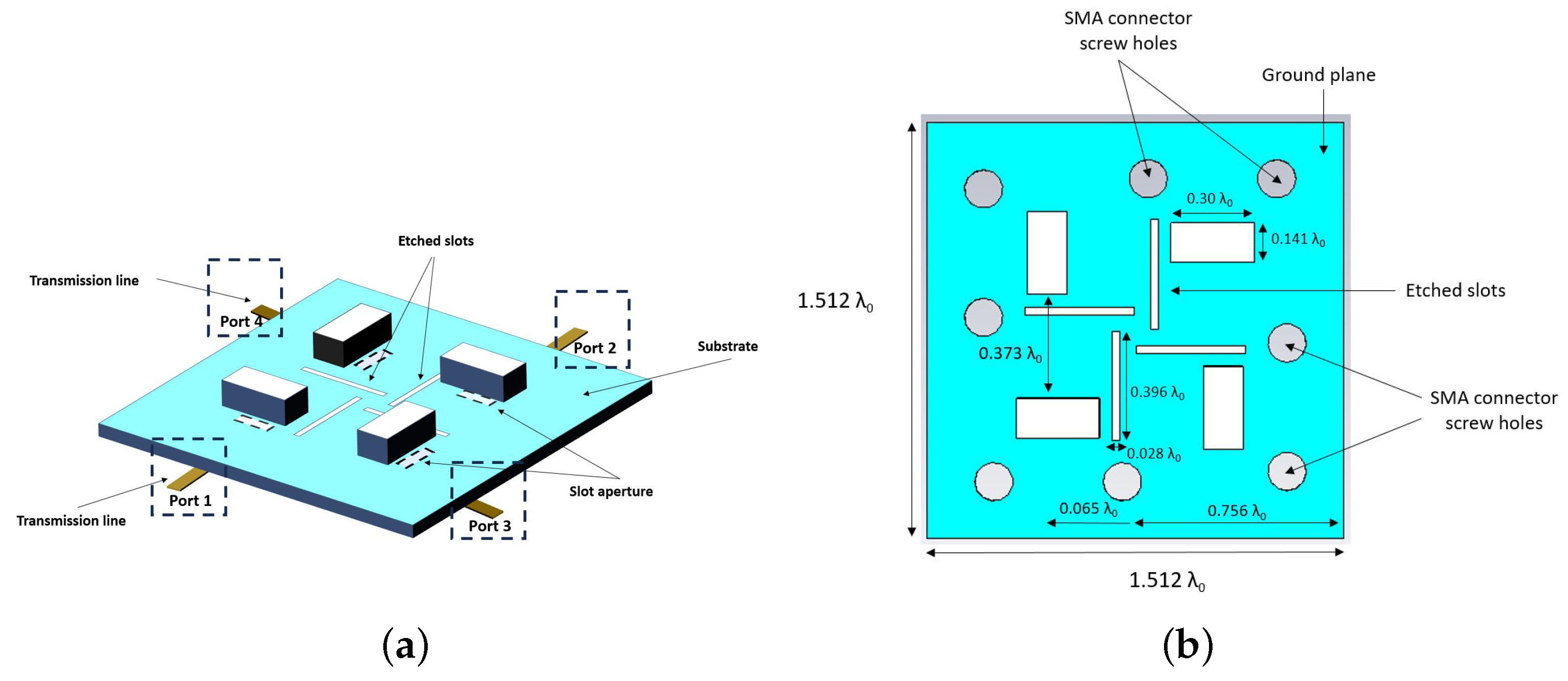
2.4.2. MIMO Antenna Design

A four element MIMO system was created based on the single element design. The antenna components were placed on a common GP with independent feeding ports, as illustrated in Figure 3. Four etched slots can be seen at 0°, 90°, 180°, and 270° to the antenna direction on the GP.
Additionally, the distance from the dielectric resonator’s (DR’s) edge to the etched slot is approximately 0.0466 λ 0 and is aligned in parallel with the position of each resonator. The etched slot dimensions are 4.25 × 0.30 mm. Each of the four RDRAs is shifted symmetrically by 0.065 λ 0 from the middle of the board on the left-hand side. Similarly to Figure 2, the antenna considers a symmetry within the four elements in addition to a similar slot aperture.
At this stage, it is pertinent to highlight that initial simulations were conducted using the CST Studio Suite 2020 for both a single element and a four element MIMO system. Subsequently, these simulations were followed by the fabrication and measurement of the systems, the results of which are presented and discussed below.

3. Experimental Methodology

The initial experimental setup involved a single scenario in which a Keysight PNA-X Network Analyzer N5245B was connected to the antenna prototype using an SMA 2.4 mm connector to measure its corresponding reflection coefficients.
Scattering parameters were measured for the 4-element design. Ports 1 and 2 were initially connected to the VNA for measuring S 11 , S 12 , S 21 , and S 22 ; the rest of the ports were terminated by 50 Ω loads. A similar procedure was employed to measure S 33 , S 34 , S 43 , and S 44 , with ports 1 and 2 terminated at 50 Ω . After completing the measurements of the parallel ports, the perpendicular S-parameters were tested. The ports of interest were connected to the VNA, and the remaining ports were terminated at 50 Ω . For instance, to measure S 13 and S 31 , ports 2 and 4 were terminated with a 50 Ω load. This methodology was consistently applied to all perpendicular ports within the design. Figure 4 shows a general diagram illustrating the experimental scenario.
Next, the antenna’s radiation pattern and gain were measured in a mmWave anechoic chamber, with the setup illustrated in Figure 5. For the single element case, the antenna design shown in Figure 2 was connected directly to the NSI-MI system. For the 4-element prototype, an additional connection was made to a power frequency splitter to verify the multi-beam capabilities of the proposed design.

4. Results and Discussion

4.1. Single Antenna Results
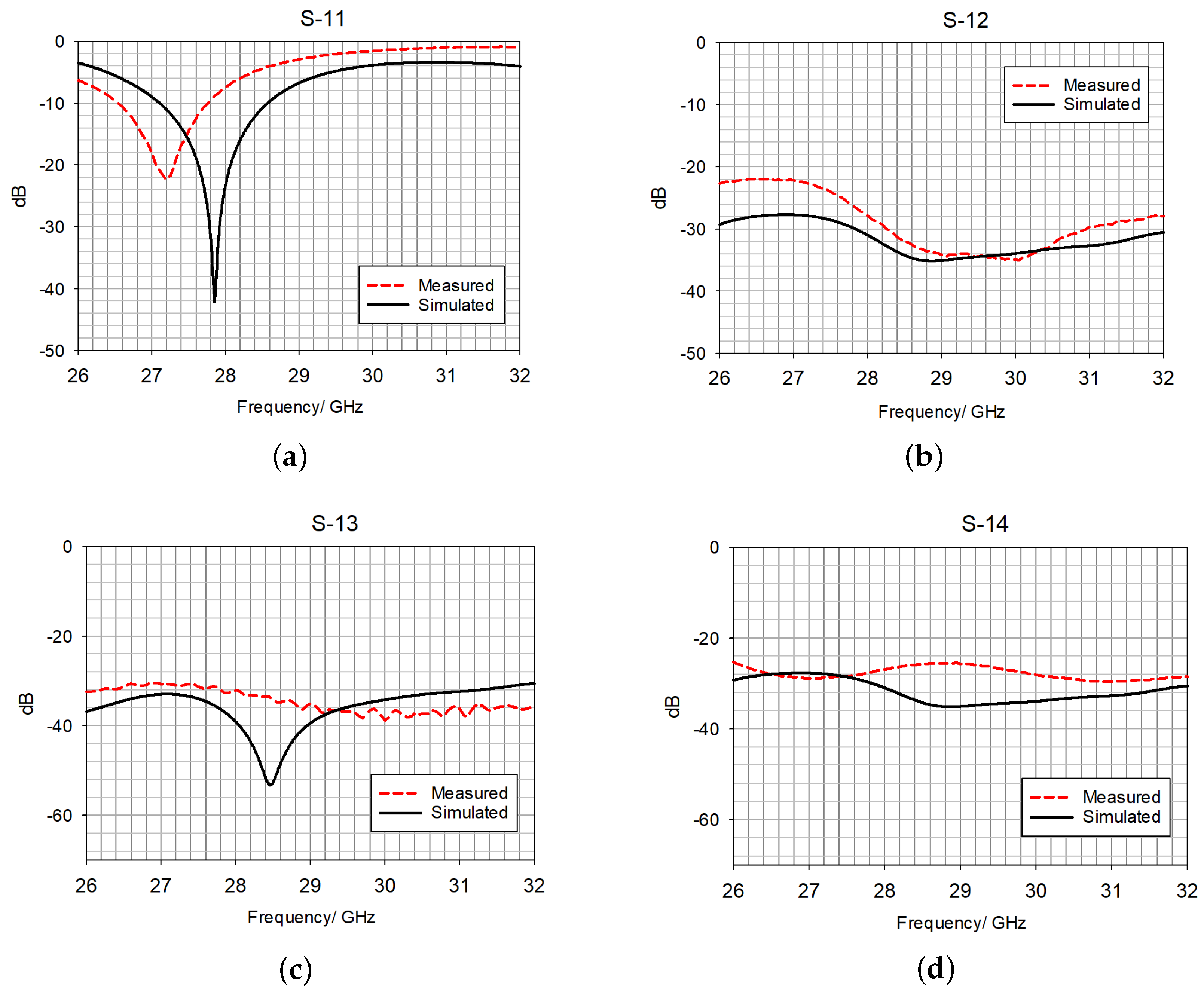
4.1.1. S-Parameters

The S-parameters resulted in a measured impedance bandwidth of 6% against 4.025% for the simulated design, as illustrated in Figure 6. The resonant frequency shifted from 28.07 GHz for the simulated design to 27.5 GHz, which is attributed to assembly and fabrication uncertainties.
The magnetic field of the single RDRA and the resonance mode at the resonant frequency, 28 GHz, are illustrated in Figure 7. In line with Figure 1, the T E 111 mode is present, and can be observed in the propagation direction.

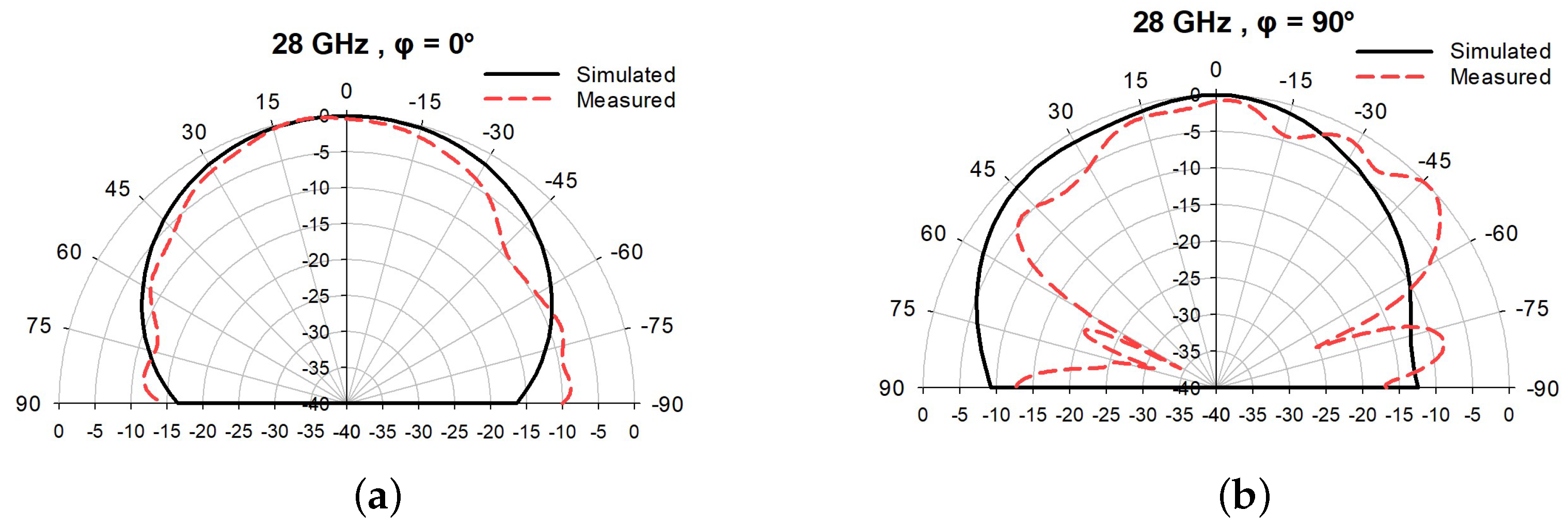
4.1.2. Antenna Radiation Pattern
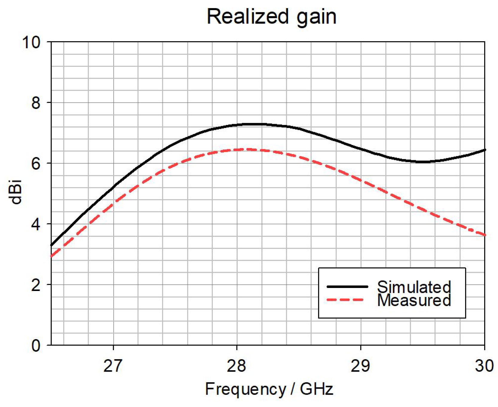
The RDRA was measured as an antenna under test (AUT) with the NSI 2000 Standard Edition Software system. The radiation pattern scanning considered a range from ϕ = −90° to ϕ = 90°. A tilting of 13° can be noted as part of the simulation. A slight tilting on the measured pattern is attributed to the antenna’s alignment. The simulations and measurements are in good agreement. Figure 8 shows the absolute value for the radiation pattern at the resonant frequency, stated below as 28 GHz.

4.1.3. Antenna Gain

The maximum realized gain in the simulations at the resonant frequency is 7.07 dBi. As illustrated in Figure 9, the measurements show a difference not bigger than 2 dBi on the frequency range and agree with the simulations. The difference is attributed to the adaptor in addition to cable losses.

4.2. MIMO Antenna Results
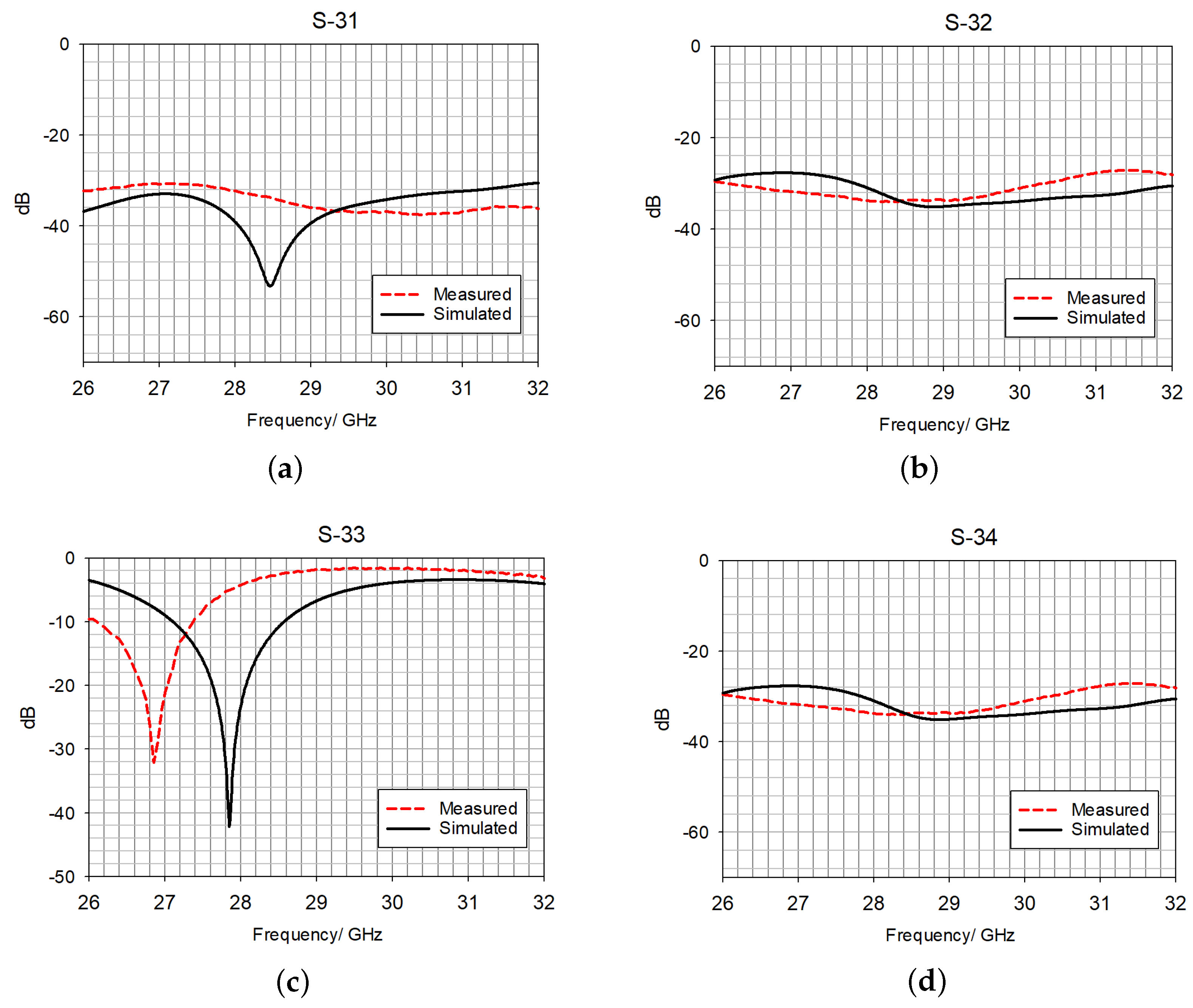
4.2.1. S-Parameters

Figure 10 presents the S 11 measurements, showing a resonant frequency of 27.5 GHz and an impedance bandwidth of 6%. By comparing them with the simulated results, the resonant frequency shifts by 300 MHz and the impedance bandwidth increases by 0.72%. The difference in the measured results is attributed to the alignment of the DR on the GP in conjunction with the fabrication tolerances. S 12 presents a maximum difference between the simulations and measurements of 5 dB within the impedance bandwidth range. S 13 has a maximum difference of 5 dB when compared with the measured and simulated results. Finally, after measuring S 14 , it can be noted that there is a maximum difference of 8 dB compared with the simulated data. It is important to mention that there is a difference between the simulated and measured results in Figure 10a,c; the RDRA alignment affects all the ports’ scattering parameter measurements by producing a shift. Additionally, there is the presence of unwanted bending of the materials due to the fragility of the prototype.
Figure 11 presents the simulated and measured scattering parameters for port 2 of the antenna structure. The S 21 measured reflection coefficients are not more than 6.5 dB bigger than in the simulations within the impedance bandwidth. For S 23 , a maximum of 5.3 dB can be observed and for S 24 a maximum 6 dB isolation can be observed. S 22 shows an impedance bandwidth of 5% compared with 5.28% for the simulated results.
Figure 12 presents the simulated and measured scattering parameters for port 3 of the antenna structure. The S 31 measurement results are not more than 2.08 dB bigger than the simulated ones within the impedance bandwidth. For S 32 , a maximum isolation of 3.76 dB can be observed, and for S 34 there is a maximum 4.8 dB difference. Finally, for S 33 , the measured impedance bandwidth is 4.46% compared with a simulated impedance bandwidth of 5.28%.
Figure 13 presents the simulated and measured scattering parameters for port 4 of the antenna structure. It can be observed that the measurements of the mutual coupling values are not more than 1.26 dB bigger than those of the simulations, within the impedance bandwidth. For S 42 , an inter-port isolation of 3.76 dB can be observed, and for S 43 a maximum 4.28 dB difference. Finally, for S 44 the measured impedance bandwidth is 4.61% compared with a simulated value of 5.28%. Although there is no change in the simulated dimensions of the RDRA, the variation in resonance frequency between the ports can be attributed to two identified factors. The first factor is the fabrication tolerances for each antenna’s dielectric resonator radiator. The second factor is the manual alignment of the DR on top of the antenna substrate.

4.2.2. Antenna Radiation Pattern

The maximum gain’s main lobe direction was first identified in the four element radiation pattern. According to the four element MIMO simulation, the main lobe is directed to 32°. Consequently, a θ = 32° azimuth plane is investigated to identify the main four element radiating lobes. Figure 14 illustrates the absolute values of the four elements at ϕ = 0. The radiation pattern is in good agreement with the simulations. Complementarily, the ϕ = 90° azimuth plane was investigated for verifying consistency in the radiation pattern. The split at θ = 0°, ϕ = 0° remains, with slight variations in the termination of the lobes at exactly θ = 90° and θ = −90°. This variation can be attributed to a systematic scan error.

4.2.3. Antenna Gain

By design, the antenna’s overall system gain is 7.06 dBi in each maximum lobe direction. By considering θ = 32° for the four simultaneous operation cases, the antenna gain is discussed below. At ϕ = 15°, a range of homogeneous differences from 1 to a maximum of 2 dBi within the frequency range is attributed to connector losses. The simulated and measured results are in good agreement. At ϕ = 90°, there is a similar behavior to the first case. The simulated and measured results are in good agreement. At ϕ = −75°, there is a maximum of 4 dBi difference at the lower frequencies within the previously mentioned impedance bandwidth. At this angle, it is important to consider the scanning range, despite the beam forming according to the simulations, there is a discrepancy in the results since the threshold maximum scanning angle is at 90°. The simulated and measured results are in good agreement. Finally, at ϕ = −173°, only simulations are presented due to the scanning range. The four cases are illustrated in Figure 15.

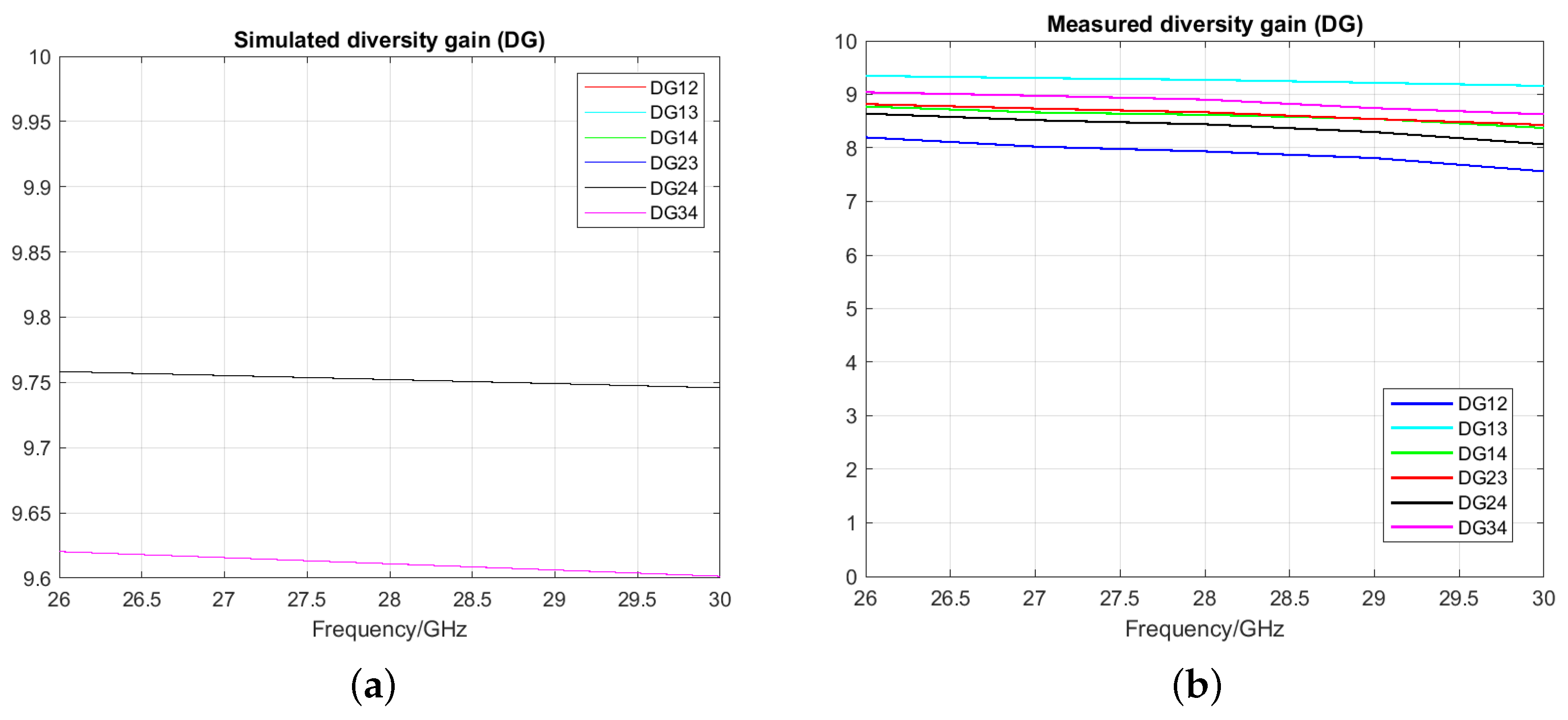
4.2.4. Envelope Correlation Coefficient (ECC) and Diversity Gain (DG)

The full radiation pattern is illustrated in Figure 16; the ECC and DG were evaluated to determine each MIMO system’s performance. Figure 17 illustrates the relationship of the inter-ports, repeatedly showing results, due to the symmetry of the design, in the range of 0.045 to 0.075.
In comparison, Figure 18 presents an increase in these results due to the interaction with a real environment, with losses coming from connectors, adaptors, and the calibration system. For this case, a range of 0.1 to 0.35 was calculated.
The simulated and measured results fulfill the MIMO ECC and DG stated threshold [26]. The simulated and measured results differences shown in Figure 17 and Figure 18 are attributed to the assembly of the RDRAs, as well as the calibration of the VNA in combination with the use of adaptor losses.

5. Conclusions

A single RDRA and a compact four-port RDRA MIMO with a constant gain of 7 dBi are presented in this work. The single element and four MIMO element designs consider a resonant frequency of 28 GHz. The antenna performance of the single RDRA element demonstrated a good agreement with computer simulations in terms of impedance bandwidth, radiation pattern, and realized gain. As a result, a four element iteration was made for creating the MIMO system. Some mutual coupling reduction mechanisms were added to the MIMO system: the antenna’s positioning and the addition of etched slots as mutual coupling mechanisms resulted in a maximum 14 dB reduction. MIMO metrics were successfully measured and compared with simulations for the iterated design, resulting in a simulated ECC < 0.075 and DG < 9.75, and a measured ECC < 0.45 and DG < 9.80, complying with MIMO thresholds. This work proposes a simultaneous MIMO 3D radiation pattern measurement in order to demonstrate four-petal radiation in addition to the employment of design mechanisms such as antenna spacing and slot etching for reducing the antenna inter-port isolation. These mechanisms demonstrate low complexity for last-mile wireless applications.

Author Contributions

E.M.-G.: design, simulation, measurements, and writing. S.K.K.: supervision and writing. Z.U.K.: writing. All authors have read and agreed to the published version of the manuscript.

Funding

This research received no external funding.

Data Availability Statement

Data are contained within the article.

Acknowledgments

This work was supported by the National Council of Humanities, Science, and Technology of Mexico (CONAHCyT). The authors would also like to acknowledge the use of the National Millimetre Wave Facility (UKRI) and thank Sideqe Askre for her support with the measurements.

Conflicts of Interest

The authors declare no conflicts of interest.

References

  1. Dahmen-Lhuissier, S. 5G. 2024. Available online: https://www.etsi.org/technologies/5g?tmpl=component (accessed on 15 January 2024).
  2. Malhat, H.; Zainud-Deen, S.; El-Hemaily, H.; Hamed, H.; AIbrahim, A. Reconfigurable circularly polarized hemispherical DRA using plasmonic graphene strips for MIMO communications. Plasmonics 2022, 17, 765–774. [Google Scholar] [CrossRef]
  3. Hussain, M.; Sharawi, M.; Podilchack, S.; Antar, Y. Closely packed millimeter-wave MIMO antenna arrays with dielectric resonator elements. In Proceedings of the 2016 10th European Conference on Antennas and Propagation (EuCAP), Davos, Switzerland, 10–15 April 2016; pp. 1–4. [Google Scholar]
  4. Dash, S.; Cheng, Q.; Khan, T.; Yadav, M.; Wang, L. 5G millimeter-wave MIMO DRAs with reduced mutual coupling. Microw. Opt. Technol. Lett. 2024, 66, e33982. [Google Scholar] [CrossRef]
  5. Sharma, A.; Rai, J.; Katiyar, H. Design of a High Gain MIMO Dielectric Resonator Antenna for 5G mm-Wave Applications. In Proceedings of the 2023 International Conference on IoT, Communication and Automation Technology (ICICAT), Gorakhpur, India, 23–24 June 2023; pp. 1–5. [Google Scholar]
  6. Zhang, Y.; Deng, J.; Li, M.; Sun, D.; Guo, L. A MIMO dielectric resonator antenna with improved isolation for 5G mm-wave applications. IEEE Antennas Wirel. Propag. Lett. 2019, 18, 747–751. [Google Scholar] [CrossRef]
  7. Pan, Y.; Qin, X.; Sun, Y.; Zheng, S. A Simple Decoupling Method for 5G Millimeter-Wave MIMO Dielectric Resonator Antennas. IEEE Trans. Antennas Propag. 2019, 67, 2224–2234. [Google Scholar] [CrossRef]
  8. Sharma, D.; Katiyar, R.; Dwivedi, A.; Nagesh, K.; Sharma, A.; Ranjan, P. Dielectric resonator-based two-port filtennas with pattern and space diversity for 5G IoT applications. Int. J. Microw. Wirel. Technol. 2023, 15, 263–270. [Google Scholar] [CrossRef]
  9. Murthy, N. Improved isolation metamaterial inspired mm-Wave MIMO dielectric resonator antenna for 5G application. Prog. Electromagn. Res. C 2020, 100, 247–261. [Google Scholar] [CrossRef]
  10. Muhammad, A.; Khan, M.; Malfajani, R.; Sharawi, M.; Alathbah, M. An Integrated DRA-Based Large Frequency Ratio Antenna System Consisting of a MM-Wave Array and a MIMO Antenna for 5G Applications. IEEE Open J. Antennas Propag. 2024, 5, 368–378. [Google Scholar] [CrossRef]
  11. Girjashankar, P.; Upadhyaya, T. Substrate integrated waveguide fed dual band quad-elements rectangular dielectric resonator MIMO antenna for millimeter wave 5G wireless communication systems. AEU-Int. J. Electron. Commun. 2021, 137, 153821. [Google Scholar] [CrossRef]
  12. Sharma, A.; Sarkar, A.; Biswas, A.; Akhtar, M. Millimeter-Wave Quad-Port Multiple-Input Multiple-Output Dielectric Resonator Antenna Excited Differentially by TE 20 Mode Substrate Integrated Waveguide. In Proceedings of the 2019 URSI Asia-Pacific Radio Science Conference (AP-RASC), New Delhi, India, 9–15 March 2019; pp. 1–4. [Google Scholar]
  13. Khan, M.; Khan, S.; Khan, O.; Aqeel, S.; Gohar, N.; Dalarsson, M. Mutual Coupling Reduction in MIMO DRA through Metamaterials. Sensors 2023, 23, 7720. [Google Scholar] [CrossRef]
  14. Karimian, R.; Kesavan, A.; Nedil, M.; Denidni, T. Low-mutual-coupling 60-GHz MIMO antenna system with frequency selective surface wall. IEEE Antennas Wirel. Propag. Lett. 2016, 16, 373–376. [Google Scholar] [CrossRef]
  15. Dadgarpour, A.; Zarghooni, B.; Virdee, B.; Denidni, T.; Kishk, A. Mutual coupling reduction in dielectric resonator antennas using metasurface shield for 60-GHz MIMO systems. IEEE Antennas Wirel. Propag. Lett. 2016, 16, 477–480. [Google Scholar] [CrossRef]
  16. Petosa, A. Dielectric Resonator Antenna Handbook; Artech: Norwood, MA, USA, 2024. [Google Scholar]
  17. McAllister, M.; Long, S.; Conway, G. Rectangular dielectric resonator antenna. Electron. Lett. 1983, 19, 218. [Google Scholar] [CrossRef]
  18. Abdulmajid, A.; Khalil, Y.; Khamas, S. Higher-Order-Mode Circularly Polarized Two-Layer Rectangular Dielectric Resonator Antenna. IEEE Antennas Wirel. Propag. Lett. 2018, 17, 1114–1117. [Google Scholar] [CrossRef]
  19. Mongia, R.K.; Ittipiboon, A. Theoretical and experimental investigations on rectangular dielectric resonator antennas. IEEE Trans. Antennas Propag. 1997, 45, 1348–1356. [Google Scholar] [CrossRef]
  20. Junker, G.; Kishk, A.; Glisson, A. Input impedance of dielectric resonator antennas excited by a coaxial probe. IEEE Trans. Antennas Propag. 1994, 42, 960–966. [Google Scholar] [CrossRef]
  21. Ibrahim, M.; Attia, H.; Cheng, Q.; Mahmoud, A. Wideband circularly polarized aperture coupled DRA array with sequential-phase feed at X-band. Alex. Eng. J. 2020, 59, 4901–4908. Available online: https://www.sciencedirect.com/science/article/pii/S1110016820304440 (accessed on 1 April 2024). [CrossRef]
  22. Mohapatra, S.; Badapanda, T.; Tripathy, S. An investigation of microwave dielectric properties of BaZr0.25Ti0.75O3 and performance of DRA for 5G application. J. Mater. Sci. Mater. Electron. 2024, 35, 167. [Google Scholar] [CrossRef]
  23. Suma, M.; Menon, S.; Bijumon, P.; Sebastian, M.; Mohanan, P. Rectangular dielectric resonator antenna on a conductor-backed co-planar waveguide. Microw. Opt. Technol. Lett. 2005, 45, 154–156. [Google Scholar] [CrossRef]
  24. Kumari, T.; Suman, K.; Gangwar, R.; Chaudhary, R. An anisotropic PRS for squinting the radiation pattern with gain improvement of MIMO system. AEU-Int. J. Electron. Commun. 2024, 176, 155150. Available online: https://www.sciencedirect.com/science/article/pii/S1434841124000359 (accessed on 1 April 2024). [CrossRef]
  25. Leung, K.; Luk, K.; Lai, K.; Lin, D. Theory and experiment of an aperture-coupled hemispherical dielectric resonator antenna. IEEE Trans. Antennas Propag. 1995, 43, 1192–1198. [Google Scholar] [CrossRef]
  26. Hong, W.; Desmond, C. MIMO-Based 5G FR1 Band Mobile Antenna. In Microwave and Millimeter-Wave Antenna Design for 5G Smartphone Applications, 1st ed.; John Wiley and Sons: Hoboken, NJ, USA, 2023; Chapter 5; pp. 125–165. [Google Scholar]
  27. Sharawi, M. Current misuses and future prospects for printed multiple-input, multiple-output antenna systems [wireless corner]. IEEE Antennas Propag. Mag. 2017, 59, 162–170. Available online: https://onlinelibrary.wiley.com/doi/abs/10.1002/9781394182459.ch5 (accessed on 19 April 2023). [CrossRef]
Figure 1. Propagation modes inside an RDRA.
Electronics 13 03280 g001
Figure 2. (a) RDRA general structure in layers. (b) Top view of the slot aperture.
Electronics 13 03280 g002
Figure 3. (a) Four port MIMO design, side view. (b) Four port MIMO design, top view.
Electronics 13 03280 g003
Figure 4. Experimental scenario for S-parameters.
Electronics 13 03280 g004
Figure 5. mmWave chamber experimental scenario.
Electronics 13 03280 g005
Figure 6. S 11 of the single RDRA element design illustrated in Figure 2a.
Electronics 13 03280 g006
Figure 7. Magnetic field distribution inside the single RDRA T E 111 at 28 GHz on the yz plane.
Electronics 13 03280 g007
Figure 8. Single element radiation pattern at (a) ϕ = 0° and (b) ϕ = 90°.
Electronics 13 03280 g008
Figure 9. Single element RDRA gain.
Electronics 13 03280 g009
Figure 10. Scattering parameters when port 1 is fed. (a) S 11 , (b) S 12 , (c) S 13 , and (d) S 14 .
Electronics 13 03280 g010
Figure 11. Scattering parameters when port 2 is fed. (a) S 21 , (b) S 22 , (c) S 23 , and (d) S 24 .
Electronics 13 03280 g011
Figure 12. Scattering parameters when port 3 is fed. (a) S 31 , (b) S 32 , (c) S 33 , and (d) S 34 .
Electronics 13 03280 g012
Figure 13. Scattering parameters when port 4 is fed. (a) S 41 , (b) S 42 , (c) S 43 , and (d) S 44 .
Electronics 13 03280 g013
Figure 14. Four element MIMO normalized radiation pattern at (a) ϕ = 0° and (b) ϕ = 90°.
Electronics 13 03280 g014
Figure 15. MIMO four-beam realized gain at (a) ϕ = 15°, (b) ϕ = 90°, (c) ϕ = −75°, and (d) ϕ = −173° at θ = 32°.
Electronics 13 03280 g015
Figure 16. Measured 3D radiation pattern for the 4-element MIMO system design illustrated in Figure 3.
Electronics 13 03280 g016
Figure 17. (a) Simulated and (b) measured ECC for MIMO.
Electronics 13 03280 g017
Figure 18. (a) Simulated and (b) measured DG for MIMO.
Electronics 13 03280 g018
Table 1. RDRA general dimensions from Figure 2.
Variable NameDimension (mm)
w s 0.48
l s 1.91
s1.73
l3.22
w1.55
h1.52
Disclaimer/Publisher’s Note: The statements, opinions and data contained in all publications are solely those of the individual author(s) and contributor(s) and not of MDPI and/or the editor(s). MDPI and/or the editor(s) disclaim responsibility for any injury to people or property resulting from any ideas, methods, instructions or products referred to in the content.

