Article

Online Mechanical Resonance Frequency Identification Method Based on an Improved Second-Order Generalized Integrator—Frequency-Locked Loop

School of Mechanical Engineering, Zhejiang Sci-Tech University, Hangzhou 310018, China
*
Author to whom correspondence should be addressed.
Electronics 2024, 13(16), 3310; https://doi.org/10.3390/electronics13163310 (registering DOI)
Submission received: 15 July 2024 / Revised: 15 August 2024 / Accepted: 19 August 2024 / Published: 21 August 2024

Abstract

:
To address the issue of mechanical resonance frequency detection in dual-inertia servo systems, this paper proposes an online identification method for mechanical resonance frequency using a low-pass filter and cascaded second-order generalized integrator—frequency-locked loop (LPF-CSOGI-FLL). Initially, the cascaded second-order generalized integrator—frequency-locked loop (CSOGI-FLL) is employed to eliminate the interference of direct current (DC) bias in resonance frequency identification. From a dual-stage structural perspective, the first second-order generalized integrator (SOGI-FLL) acts as a band-pass pre-filter to extract the mechanical resonance signal from the signal to be tested. The second SOGI-FLL generates a signal with equal amplitude and frequency to the mechanical resonance and obtains the frequency of the resonance signal through the frequency-locked loop. Subsequently, a low-pass filter (LPF) is applied to the frequency feedback loop of the second-stage SOGI-FLL, effectively reducing the oscillation of the estimated frequency. Finally, combining the CSOGI-FLL with an LPF forms a novel structure, namely, LPF-CSOGI-FLL. The results demonstrate that the proposed method significantly improves the detection accuracy of mechanical resonance frequency under various conditions. Compared to traditional offline techniques, this method overcomes the impact of resonance frequency drift and enhances system stability.

1. Introduction

Permanent magnet synchronous motor (PMSM) servo systems, with their extensive speed regulation range, play a crucial role in high-precision motion control applications such as industrial robots, machining centers, and aerospace technology [1]. In these applications, flexible coupling systems are essential due to their versatility and adaptability. However, the presence of flexible coupling loads in servo systems can induce mechanical resonances, which not only compromise the system’s accuracy and stability but also degrade performance over time, potentially leading to equipment damage and safety hazards. Therefore, a thorough analysis and effective suppression of mechanical resonances in servo drive systems are imperative.
In this context, researchers have conducted extensive studies on methods for suppressing mechanical resonance in servo drive systems [2,3,4], proposing various approaches and control strategies. Early research primarily focused on improvements to mechanical structures [5,6]. However, these methods are limited by increased design costs and complexity. With continuous technological advancements, control strategies have become the primary means of addressing resonance issues in servo systems. These strategies can be classified into active and passive categories [7]. Active control strategies primarily suppress resonance by adjusting controller parameters or system structures [8,9]. Although effective, these methods often involve complex designs and high computational demands, posing significant challenges for practical applications. Conversely, passive control strategies eliminate resonance by identifying resonance frequency points and employing correction or compensation mechanisms without altering the system structure or control parameters [10]. Notch filters are commonly used in these strategies due to their simplicity, low cost, and notable effectiveness in practical applications, making them widely accepted.
In practical applications, factors such as damping, discretization, and system inertia often cause the actual resonance frequency to deviate from the natural frequency. In this context, accurate frequency identification techniques are crucial for effective mechanical resonance suppression. Currently, resonance frequency identification methods are primarily categorized into offline and online techniques. While offline identification provides a high accuracy in parameter estimation, it lacks adaptability to dynamic system changes, especially in cases of frequency drift. Conversely, online identification methods can adapt to real-time system variations and effectively suppress resonance, making them more prevalent in practical applications. Recent years have seen the development of new methods to enhance the accuracy of online resonance frequency identification. For instance, in [11], the authors proposed a frequency estimation method based on three discrete Fourier transform (DFT) spectral lines, which offers a high identification accuracy and strong signal tracking capability. Additionally, in ref. [12], the authors proposed a robust adaptive notch filter (ANF) to address the complex resonance issues encountered in two-mass servo systems. This method involves detecting oscillations and estimating the frequency of the oscillating signals to adjust the notch filter online, thereby handling oscillations across varying frequencies and amplitudes. Moreover, in ref. [13], the authors improved the forgetting factor in the recursive least squares (RLS) algorithm to achieve online resonance frequency estimation. Despite these advancements in resonance frequency identification, the increased computational complexity of these methods’ control structures and implementations limits their application in practical systems.
The second-order generalized integrator (SOGI) is renowned for its excellent band-pass filtering capabilities, effectively eliminating noise and harmonic interference, making it highly valuable in frequency identification applications [14]. Building on the development of the SOGI, researchers introduced the frequency-locked loop (FLL), resulting in the SOGI-FLL system. This system accurately identifies the frequency and amplitude of input signals and has found extensive applications in the power and energy sectors [15]. However, the standard SOGI-FLL has limitations in suppressing power grid voltage disturbances. To address this issue, in [16], the authors proposed two improved SOGI-FLL structures, providing theoretical foundations and implementation schemes to enhance system performance.
Under the regulation of the FLL, the SOGI achieves consistency with the input signal frequency, enabling the precise tracking of the input signal. The SOGI-FLL simplifies the algorithm structure by extracting only frequency information, significantly reducing computational time and space complexity. As an efficient signal processing and synchronization tool, the FLL has been widely adopted in various engineering applications [17]. In power grid synchronization and motor control, the SOGI-FLL has gained widespread attention for its superior performance. In power grid synchronization applications, in [18,19], the authors proposed improved FLL techniques to enhance robustness, adaptability, disturbance rejection, and noise immunity in power grid applications. Additionally, in the motor control field, the excellent band-pass filtering capability of the SOGI and the synchronization and frequency identification advantages of the FLL have been fully utilized. In [20,21], the authors applied the SOGI-FLL to motor parameter estimation problems, significantly improving system performance.
In summary, the SOGI-FLL is an effective frequency identification method. However, due to the complexity of mechanical resonance signals in dual-inertia servo systems, the traditional SOGI-FLL may fail to accurately track input signals, thereby affecting its performance in practical applications. To address these issues, an online mechanical resonance frequency identification method based on the LPF-CSOGI-FLL is proposed. This method utilizes a CSOGI-FLL to effectively eliminate the influence of DC components on resonance frequency identification, and incorporates an LPF to significantly reduce frequency estimation oscillations, thus enhancing the accuracy of resonance frequency identification.
The remainder of this paper is organized as follows: Section 1 introduces the mechanism of mechanical resonance in dual-inertia systems, providing the theoretical foundation for the study. Section 2 designs and analyzes the proposed resonance suppression strategy in detail, demonstrating its theoretical advantages. In Section 3, experiments on a PMSM drive system are conducted to verify the effectiveness of the proposed control strategy. Finally, Section 4 summarizes the findings of this study.

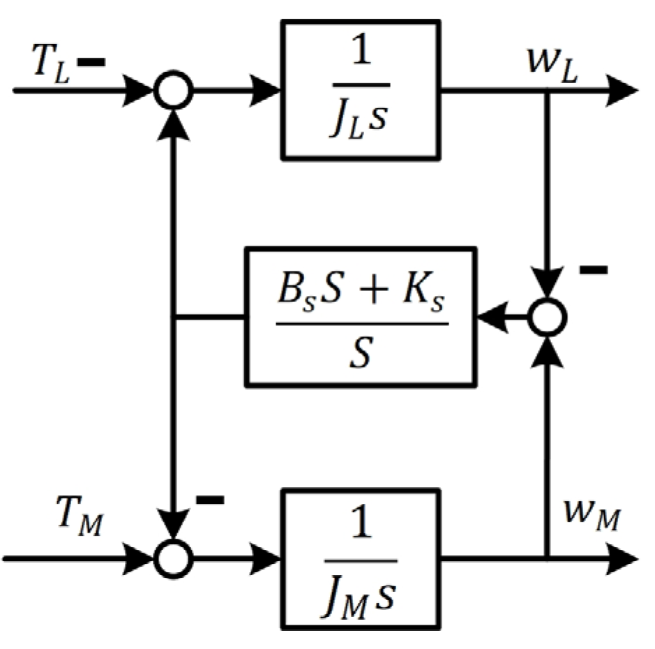
2. Mechanism of Mechanical Resonance

In servo systems, the simplified model of a dual-inertia system, composed of the motor, load, and transmission device, is shown in Figure 1. In this model, J m represents the moment of inertia of the motor, and J L represents the moment of inertia of the load. w m is the angular velocity of the motor, and w L is the angular velocity of the load. T m denotes the electromagnetic torque of the motor, and T L denotes the torque of the load. θ m is the rotational angle of the motor, and θ L is the rotational angle of the load. K s is the stiffness coefficient of the transmission shaft, and T s is the torque between the motor and the shaft. B s represents the damping coefficient of the transmission shaft.
Based on the equivalent block diagram of the dual-inertia system shown in Figure 2, the following dynamic equations are established [22]:
J m θ ¨ m = T L T s J L θ ¨ L = T s T L T s = K s θ m θ L + B s θ ˙ m θ ˙ L
From these equations, the transfer function between the motor angular velocity and the electromagnetic torque is derived:
G M ( s ) = ω m T m = 1 J M + J L s G g ( s ) J L s 2 + B s s + K s J p s 2 + B s s + K s G r ( s )
J p = J M J L J M + J L
where J p represents the equivalent moment of inertia of the system, G g ( s ) is the transfer function from the motor torque to the motor end speed without considering the flexibility of the transmission mechanism, and G r ( s ) is the flexibility term introduced by the transmission mechanism. The flexibility term G r ( s ) is expressed as:
G r ( s ) = ( s / ω A R ) 2 + 2 ξ A R ω A R s + 1 ( s / ω R ) 2 + 2 ξ R ω R s + 1
The poles and zeros of G r ( s ) are obtained through calculations as follows:
w A R = K s J L w R = K s J p
ε A R = B s 2 J L K s ε R = B s 2 J p K s
where w A R and ε A R are the anti-resonance frequency and damping, and w R and ε R are the resonance frequency and damping, respectively.

3. Principle of LPF-CSOGI-FLL

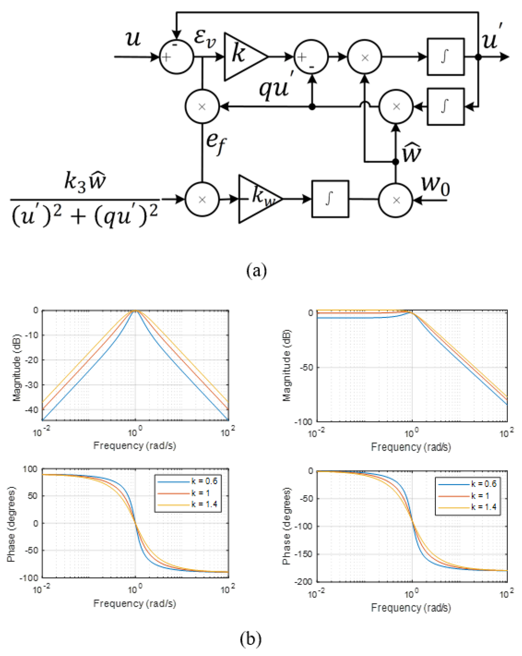
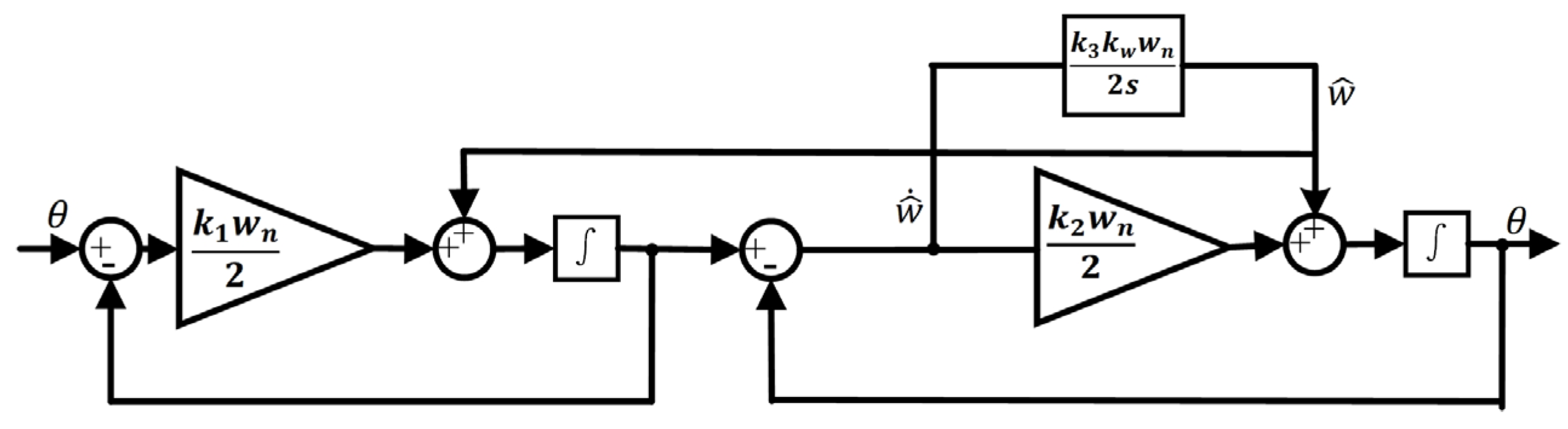
3.1. Traditional SOGI-FLL

The SOGI-FLL is an efficient frequency-adaptive filter composed of two main components: the SOGI-based quadrature signal generator (SOGI-QSG) and the frequency-locked loop (FLL). The structural diagram is shown in Figure 3. In this structure, u represents the input sampled signal, u is the filtered in-phase signal, q u is the filtered quadrature signal, ε v is the synchronization error, and the frequency error signal e f serves as the input to the FLL. w 0 is the initial set frequency, and w ^ is the estimated frequency:
D ( s ) = u u ( s ) = k ω n s s 2 + k ω n s + ω n 2
Q ( s ) = q u u ( s ) = k ω n 2 s 2 + k ω n s + ω n 2
where D s and Q s are the transfer functions of the two orthogonal outputs of the SOGI-FLL.
Setting the center frequency of the SOGI to 100 Hz, the Bode plots of the SOGI under different gain parameters k were analyzed, as shown in Figure 3b. Based on these analyses, the significant impact of the gain parameter k on the performance of the SOGI can be summarized as follows:
  • Lower gain values enhance the filtering effect, while higher gain values improve the system’s response speed and bandwidth range. However, high gain values may reduce the precision of extracting specific frequency signals, thereby affecting the overall system performance.
  • From the input to the output perspective, the band-pass filtering characteristics exhibited by D s can effectively suppress DC components and low-frequency signals to a certain extent. However, since Q s exhibits low-pass filtering characteristics, the presence of DC or low-frequency components in the input signal u may adversely affect the output quadrature signal and frequency-locking performance. In such cases, the DC component can influence the frequency estimation of the SOGI-FLL, further affecting the overall system performance [21].
To simplify the tuning process of the control parameters, a linearized mathematical model was established. The linearization method for this model follows the SOGI-FLL linearization process proposed in the literature [15]. The final linearized model of the SOGI-FLL is shown in Figure 4.
The closed-loop transfer function of the SOGI-FLL, derived from the linearized dynamic model, is as follows:
V ^ ( s ) = k ω n / 2 s + k ω n / 2 V ( s )
θ ^ ( s ) = k ω n / 2 s + k 1 k w ω n / 2 s 2 + k ω n / 2 s + k 1 k w ω n / 2 θ ( s )
ω ^ ( s ) = k 1 k w ω n / 2 s 2 + k ω n / 2 s + k 1 k w ω n / 2 ω ( s )
The characteristic polynomial derived from transfer functions (10) and (11) is as follows:
s 2 + k 1 ω n 2 2 ζ ω n s + k 1 k w ω n 2 w n 2 = 0
where w n is the undamped natural angular frequency.
Based on Equation (12), the gain k w of the FLL and the undamped natural angular frequency w n can be determined as follows:
k w = 2 w n 2 k 1 w n ω n = k 1 ω n 4 ζ
As seen from Equation (13), the gain k w and w n of the FLL are primarily influenced by the damping factor ζ. A larger ζ results in a faster system response but may reduce the system’s ability to filter harmonics.
The performance of the SOGI-FLL can be optimized by selecting an appropriate SOGI gain k w . To achieve an optimal balance between a good dynamic response and signal extraction quality, this study sets the damping factor ζ to 0.707, w n to 628, and   k 1 to 1.414, resulting in k w = 222 .
The SOGI-FLL is an efficient frequency-adaptive filter commonly used in various applications. However, when there is DC bias or harmonic interference in the input signal, the interference suppression ability of the traditional SOGI-FLL is compromised, leading to fluctuations in frequency estimation and potential errors.
To overcome these limitations, this study proposes a novel CSOGI-FLL structure. The CSOGI-FLL integrates an adaptive pre-filter with the SOGI-FLL in a cascaded arrangement, as shown in Figure 5. The adaptive pre-filter extracts the mechanical resonance components from the sampled signal and feeds them into the SOGI-FLL, which then accurately locks onto the frequency, even in the presence of DC bias or harmonic disturbances. Unlike the SOGI-FLL, the pre-filter does not include an FLL to adjust the center frequency. Instead, it uses the frequency feedback mechanism of the SOGI-FLL to adapt to variations in the mechanical resonance frequency, thereby replacing the original FLL function.
Through this cascading approach, the CSOGI-FLL not only maintains the advantages of the traditional SOGI-FLL but also significantly improves its robustness and accuracy in challenging environments.
Based on the previously described SOGI-FLL linearization method, the steady-state characteristics of the CSOGI-FLL were obtained, as shown in Figure 6.
V ^ ( s ) = k 1 ω n / 2 k 2 ω n / 2 s + k 1 ω n / 2 s + k 2 ω n / 2 V ( s )
Equation (14) defines the open-loop transfer function of the CSOGI. Assuming w ^ n is the mechanical resonance frequency, the Bode plots for different gain values k were analyzed, as shown in Figure 6b. From these analyses, the following observations can be made:
A lower cutoff frequency indicates that the filter can more effectively suppress high-frequency signal components. The cutoff frequency of the CSOGI is lower than that of the SOGI, enhancing the CSOGI’s performance in mitigating high-frequency interference. Furthermore, for signal components beyond the cutoff frequency, the CSOGI can attenuate their amplitude more rapidly than the SOGI. This means that the CSOGI attenuates to zero faster than the SOGI, strengthening its ability to handle sudden high-frequency disturbances. Therefore, the CSOGI exhibits superior filtering characteristics compared to the SOGI.
From the above analysis, the following conclusions can be drawn: When using the SOGI method, increasing the k value can effectively expand the system’s bandwidth, thereby enhancing its adaptability to frequency variations. However, a higher k value may diminish the system’s ability to attenuate resonance. In contrast, when employing the CSOGI method, by adjusting the k value of each cascaded unit, the system can not only quickly respond to frequency changes but also maintain an excellent harmonic attenuation performance.
Following the previously described SOGI-FLL linearization process, the dynamic characteristics of the CSOGI-FLL were obtained, as shown in Figure 7.
Using the linearized dynamic model of the CSOGI-FLL, the linearized transfer function of the CSOGI-FLL’s dynamic characteristics can be derived as follows:
θ ^ ( s ) = k 1 k 2 ω n 2 / 4 s + k 1 k 3 k w w n 2 / 4 s 3 + k 1 + k 2 ω n / 2 s 2 + k 1 k 2 ω n 2 / 4 s + k 1 k 3 k w w n 2 / 4 θ ( s )
ω ^ ( s ) = k 1 k 3 k w w n 2 / 4 s 3 + k 1 + k 2 ω n / 2 s 2 + k 1 k 2 ω n 2 / 4 s + k 1 k 3 k w w n 2 / 4 ω ( s )
The characteristic polynomial derived from transfer function (16) is as follows:
s 3 + k 1 + k 2 ω n / 2 s 2 + k 1 k 2 ω n 2 / 4 s + k 1 k 3 k w w n 2 / 4 = 0
where k w can be expressed as:
k w = 2 ( ζ + 1 ) ω n k 1 ( 2 ζ + 1 ) 3
Given that k 1 = k 2 = 1.414 , and by selecting the optimal damping factor ζ = 0.707, the gain k w of the FLL can be calculated as k w = 108 .

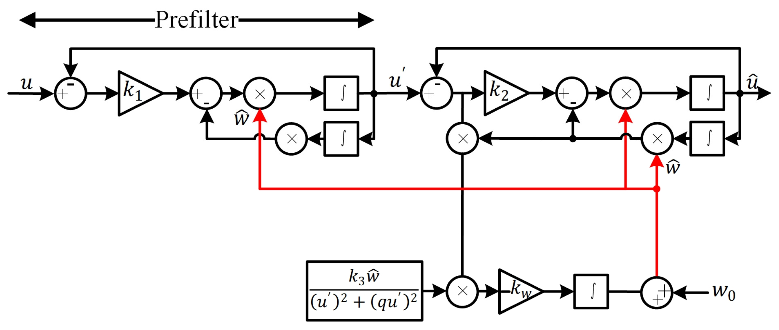
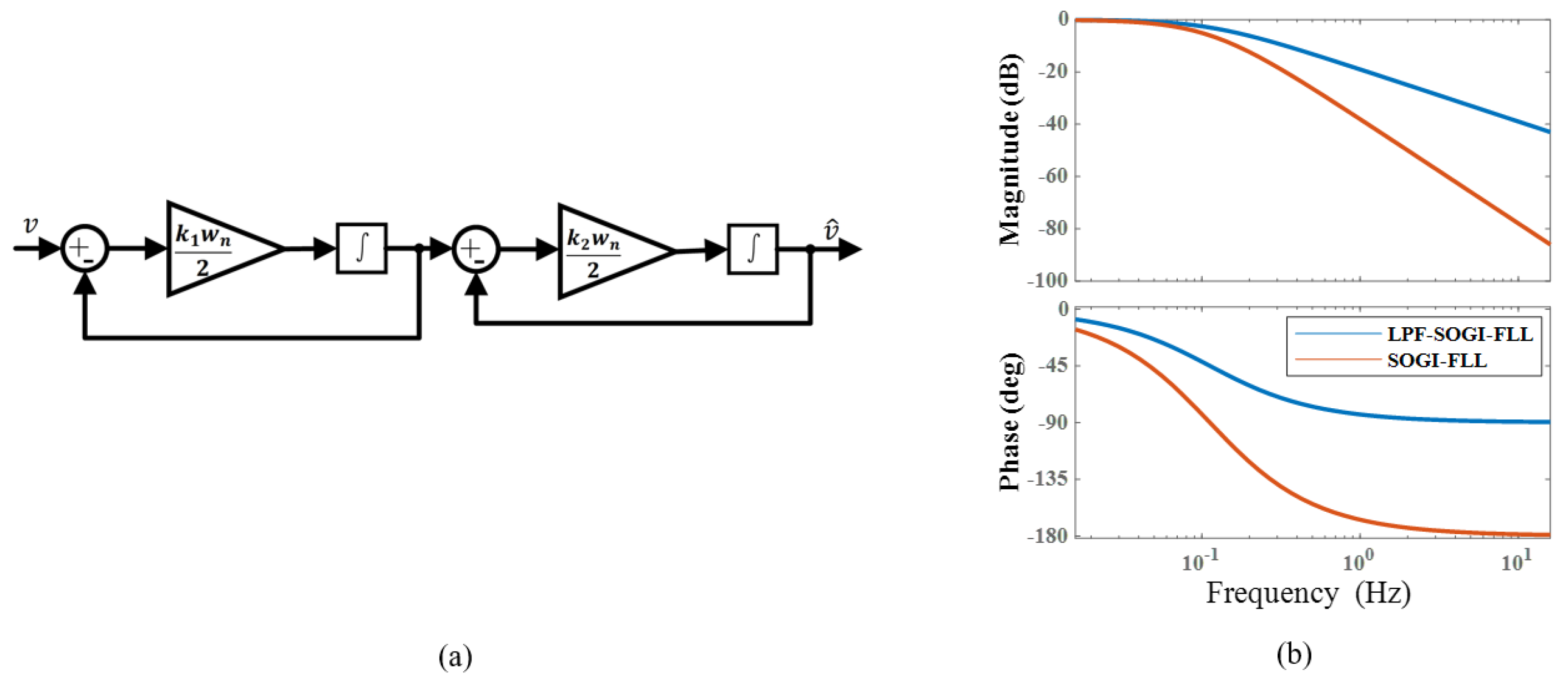
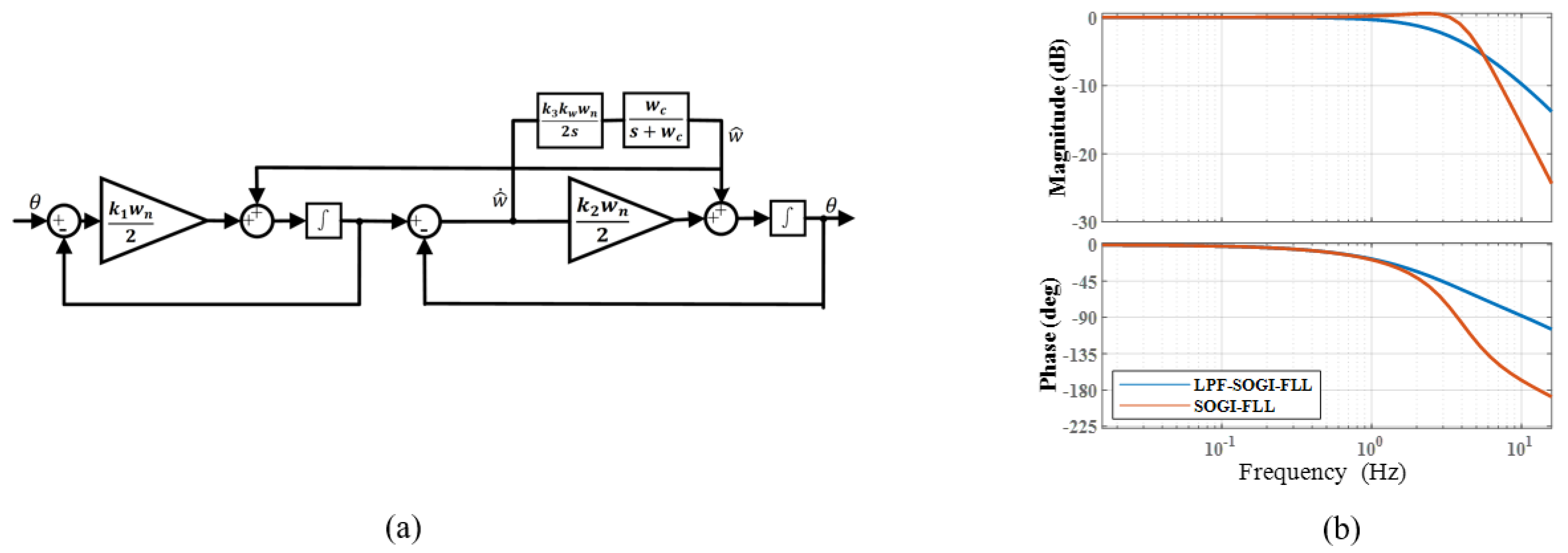
3.2. Low-Pass Filter-Cascaded Second-Order Generalized Integrator—Frequency-Locked Loop

To overcome the issue of frequency estimation oscillation, the proposed structure of the LPF-CSOGI-FLL is shown in Figure 8. In this structure, an LPF is used in the frequency feedback loop of the second-stage SOGI-FLL.
The linearized steady-state characteristics model of the DCI-CSOGI-LPF is similar to that of the CSOGI-FLL. The linearized dynamic characteristics model of the DCI-CSOGI-LPF is shown in Figure 9.
Based on the linearized structure in Figure 9a, the linearized transfer function for the dynamic characteristics of LPF-SOGI-FLL can be derived as follows:
θ ^ ( s ) = k 1 k 2 ω n 2 / 4 s + k 1 k 3 k w w n 2 w c / ( 4 ( s + w c ) ) s 3 + k 1 + k 2 ω n / 2 s 2 + k 1 k 2 ω n 2 / 4 s + k 1 k 3 k w w n 2 w c / ( 4 ( s + w c ) ) θ ( s )
ω ^ ( s ) = k 1 k 3 k w w n 2 w c / ( 4 ( s + w c ) ) s 3 + k 1 + k 2 ω n / 2 s 2 + k 1 k 2 ω n 2 / 4 s + k 1 k 3 k w w n 2 w c / ( 4 ( s + w c ) ) ω ( s )
As shown in Figure 9b, the LPF-CSOGI-FLL enhances the system’s order by incorporating an LPF in the frequency feedback loop of the second-stage SOGI-FLL. This structural adjustment extends the closed-loop bandwidth of the FLL, allowing for a rapid response to changes in the resonance frequency. Moreover, for high-frequency resonance components beyond the cutoff frequency, the LPF-CSOGI-FLL attenuates their amplitude more quickly than the SOGI-FLL. Therefore, the LPF-CSOGI-FLL outperforms the SOGI-FLL in reducing frequency estimation oscillations and improving the accuracy and stability of frequency estimation.

4. Experimental Verification

To verify the effectiveness of the LPF-CSOGI-FLL in detecting mechanical resonance frequencies, the control block diagram shown in Figure 10 was implemented based on the vector control of a PMSM. The system comprises a speed loop based on a proportional–integral (PI) controller, a current loop also based on a PI controller, a frequency detection module, a notch filter, and a dual-inertia system. The LPF-CSOGI-FLL method is employed to identify the resonance frequency points from the speed error, and the notch filter is then cascaded into the speed loop. By adaptively adjusting the parameters of the notch filter in real time based on the detected resonance frequency, the current output of the speed controller is filtered to suppress current fluctuations. This, in turn, suppresses the fluctuations in electromagnetic torque, effectively mitigating system resonance.
To further verify the effectiveness of the proposed LPF-CSOGI-FLL-based online mechanical resonance frequency identification strategy, the motor drive test platform was constructed as shown in Figure 11. The main parts of the control system platform, including the PMSM, power supply, and control board, are labeled in the figure. The control system platform consists of two main parts: the power circuit and the control circuit. In the power circuit, insulated gate bipolar transistor (IGBT) is used as the switching device, and the core control chip is the STM32F103RCT6. The parameters of the PMSM used in the experiment are listed in Table 1.

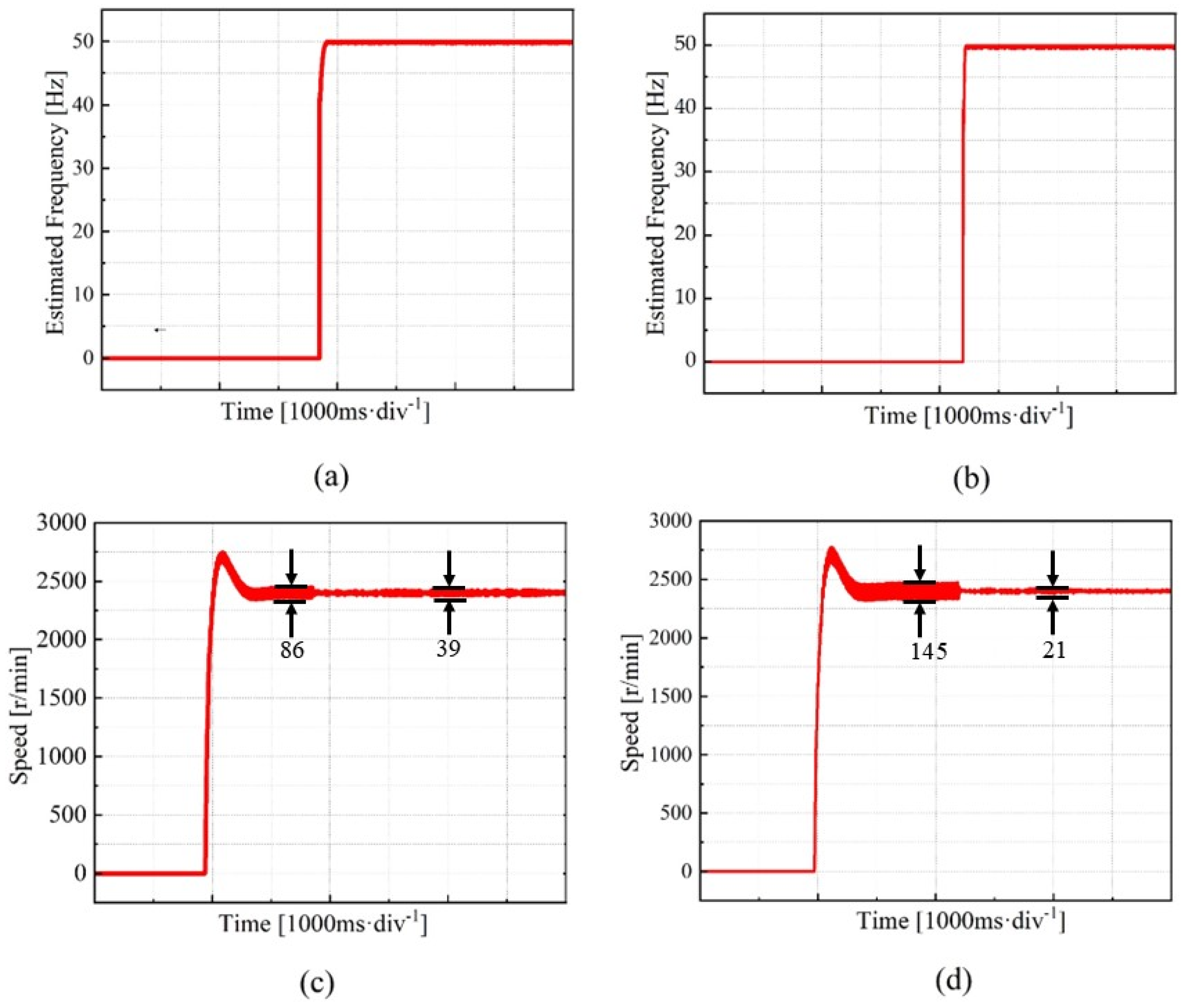
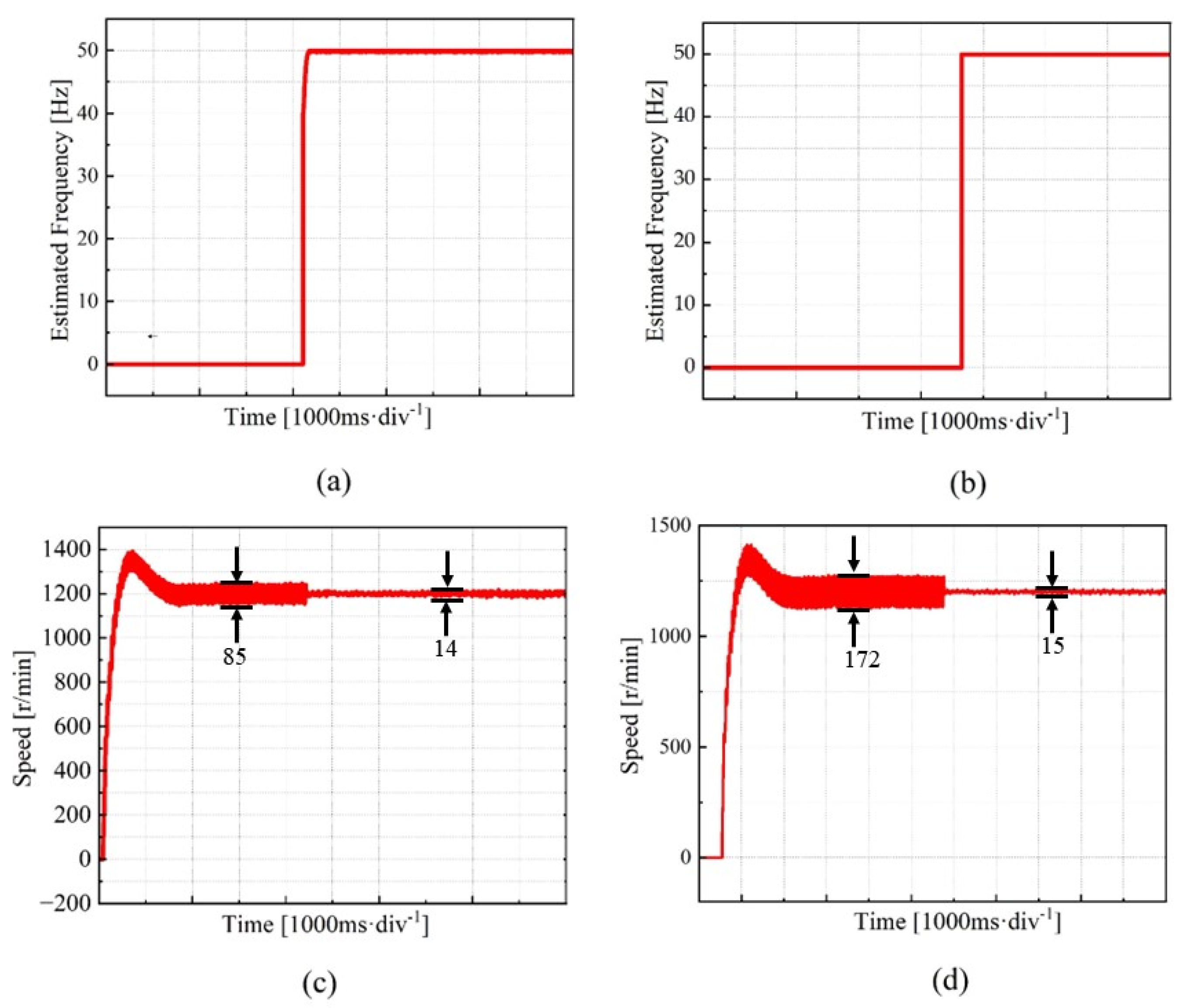
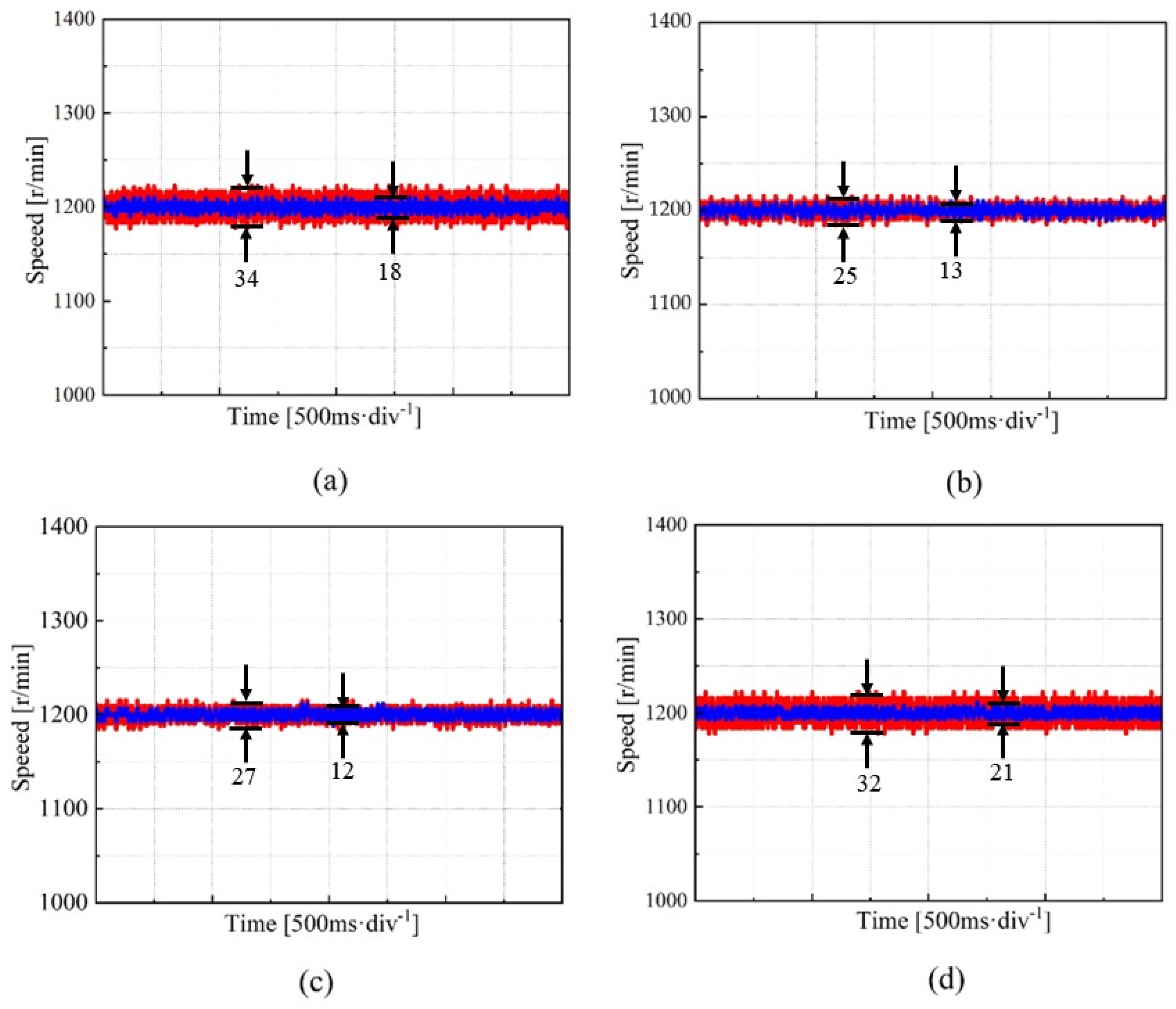
4.1. Analysis of Motor Stability Performance with the Introduction of LPF-CSOGI-FLL

To thoroughly investigate the effect of the LPF-CSOGI-FLL strategy on improving motor stability, we applied different resonances at rotational speeds of 500 r/min and 2000 r/min. The analysis focused on the accuracy of mechanical resonance frequency identification and the speed response. In the experiments, the mechanical resonance frequencies were set to 50 Hz and 100 Hz, respectively. The parameters for the LPF-CSOGI-FLL were configured as follows: k 1 = 1.414 , k 2 = 1.414 , and k w = 20 . The parameters for the notch filter were set as follows: bandwidth of 0.25 Hz, depth of 0.5 dB, and filter bandwidth of 10 π rad/s.
We applied the CSOGI-FLL and LPF-CSOGI-FLL methods for mechanical resonance suppression. The results of mechanical resonance frequency identification for the motor under low-speed and low-frequency conditions using the CSOGI-FLL and LPF-CSOGI-FLL methods are shown in Figure 12. As seen in Figure 12a, the output mechanical resonance frequency response under low-frequency and low-amplitude conditions is presented. Figure 12b illustrates that, without using the LPF-CSOGI-FLL method, the speed fluctuation rate of the PMSM under low-frequency and low-amplitude conditions is 7.67%. When the LPF-CSOGI-FLL method is applied under the same conditions, the speed fluctuation rate of the PMSM decreases to 1.83%. Figure 12c shows the output mechanical resonance frequency response under low-frequency and high-amplitude conditions. Figure 12d demonstrates that, without the LPF-CSOGI-FLL method, the speed fluctuation rate of the PMSM under low-frequency and high-amplitude conditions is 12.66%. With the LPF-CSOGI-FLL method, the speed fluctuation rate decreases to 1.70% under the same conditions.
The results of mechanical resonance frequency identification and suppression using the CSOGI-FLL and LPF-CSOGI-FLL methods under low-speed and high-frequency conditions are shown in Figure 13. As shown in Figure 13a, the output mechanical resonance frequency response under high-frequency and low-amplitude conditions is presented. Figure 13b indicates that, under high-frequency and low-amplitude conditions, the speed fluctuation rate of the PMSM without the LPF-CSOGI-FLL method is 19.54%. When using the LPF-CSOGI-FLL method under the same conditions, the speed fluctuation rate of the PMSM decreases to 1.97%. Figure 13c shows the output mechanical resonance frequency response under high-frequency and high-amplitude conditions. Figure 13d illustrates that, under high-frequency and high-amplitude conditions, the speed fluctuation rate of the PMSM without the LPF-CSOGI-FLL method is 12.13%. When using the LPF-CSOGI-FLL method under the same conditions, the speed fluctuation rate of the PMSM decreases to 1.54%.
The results of mechanical resonance frequency identification and suppression using the CSOGI-FLL and LPF-CSOGI-FLL methods under high-speed and low-frequency conditions are shown in Figure 14. As shown in Figure 14a, the output mechanical resonance frequency response under low-frequency and low-amplitude conditions is presented. Figure 14b indicates that, under low-frequency and low-amplitude conditions, the speed fluctuation rate of the PMSM without the LPF-CSOGI-FLL method is 3.65%. When using the LPF-CSOGI-FLL method under the same conditions, the speed fluctuation rate of the PMSM decreases to 1.83%. Figure 14c shows the output mechanical resonance frequency response under low-frequency and high-amplitude conditions. Figure 14d illustrates that, under low-frequency and high-amplitude conditions, the speed fluctuation rate of the PMSM without the LPF-CSOGI-FLL method is 6.30%. When using the LPF-CSOGI-FLL method under the same conditions, the speed fluctuation rate of the PMSM decreases to 2.19%.
The results of mechanical resonance frequency identification and suppression using the CSOGI-FLL and LPF-CSOGI-FLL methods under high-speed and high-frequency conditions are shown in Figure 15. As shown in Figure 15a, the output mechanical resonance frequency response under high-frequency and low-amplitude conditions is presented. Figure 15b indicates that, under high-frequency and low-amplitude conditions, the speed fluctuation rate of the PMSM without the LPF-CSOGI-FLL method is 3.67%. When using the LPF-CSOGI-FLL method under the same conditions, the speed fluctuation rate of the PMSM decreases to 0.98%. Figure 15c shows the output mechanical resonance frequency response under high-frequency and high-amplitude conditions. Figure 15d illustrates that, under high-frequency and high-amplitude conditions, the speed fluctuation rate of the PMSM without the LPF-CSOGI-FLL method is 6.31%. When using the LPF-CSOGI-FLL method under the same conditions, the speed fluctuation rate of the PMSM decreases to 1.42%.
The experimental results demonstrate the significant advantages of the LPF-CSOGI-FLL method in suppressing mechanical resonance. Under both low-speed and high-speed conditions, and regardless of whether the frequency is low or high or the amplitude is low or high, the LPF-CSOGI-FLL method substantially reduces the speed fluctuation rate of the PMSM. Specifically, under low-speed and low-frequency conditions, the speed fluctuation rate of the PMSM decreases from 7.67% to 1.83% when using the LPF-CSOGI-FLL method. Under low-speed and high-frequency conditions, the fluctuation rate decreases from 12.66% to 1.70%. Similarly, under high-speed and low-frequency conditions, the fluctuation rate decreases from 3.65% to 1.83%, and under high-speed and high-frequency conditions, the fluctuation rate decreases from 6.30% to 2.19%.

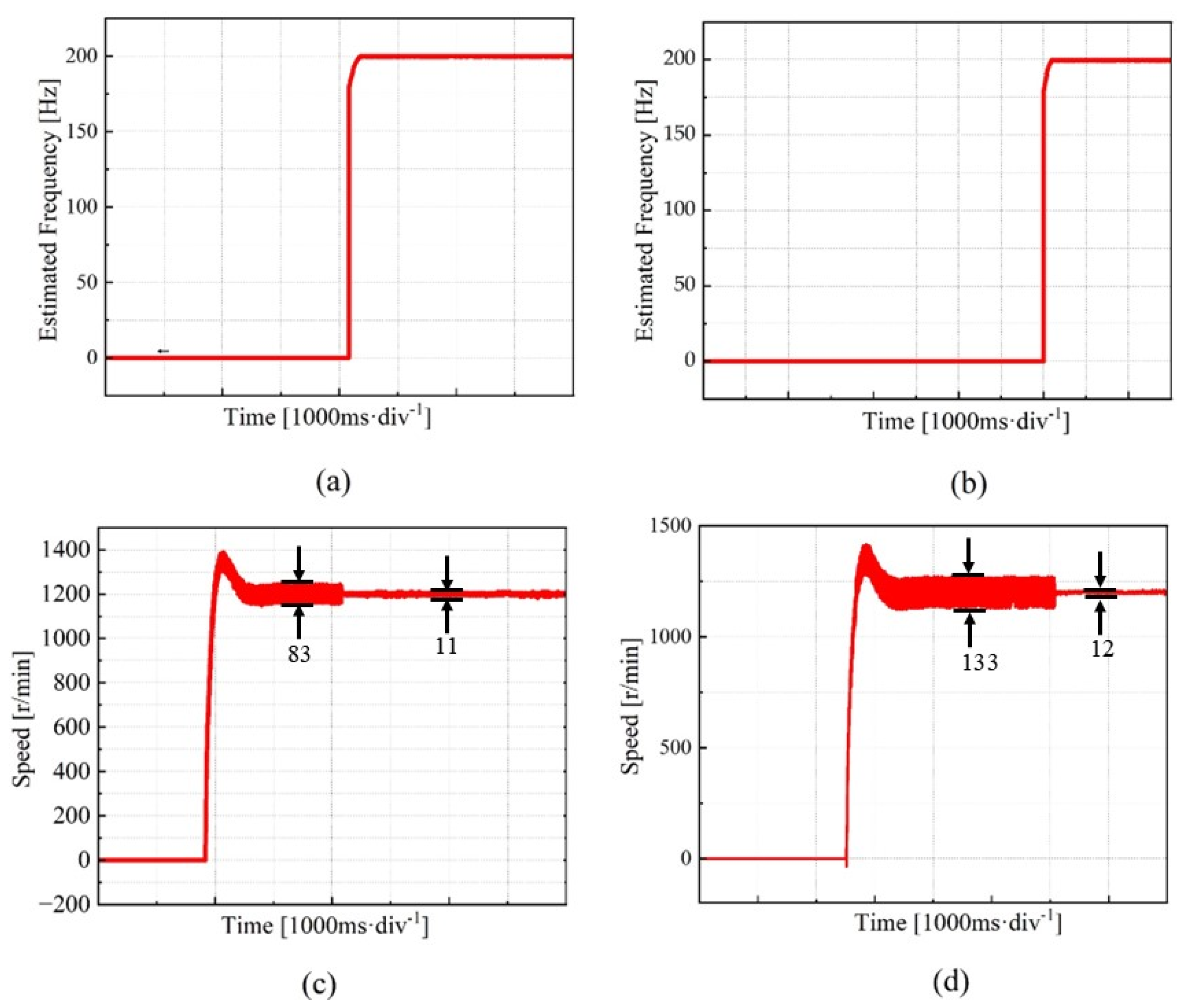
4.2. Comparison of Online and Offline Identification Performance under Mechanical Resonance Frequency Drift

Experiment 2 examines the ability of the LPF-CSOGI-FLL algorithm to adapt in real time to changes in resonance frequency under conditions of mechanical resonance frequency drift, and compares its performance with offline identification methods based on preset parameters.
The speed response results of the PMSM under low-speed operation using both offline and online resonance suppression methods are shown in Figure 16. As depicted in Figure 16a, under low-frequency and low-amplitude conditions, the speed fluctuation rate of the motor measured using the offline resonance suppression method is 2.61%. When using the online resonance suppression method under the same conditions, the speed fluctuation rate improves to 1.40%. Figure 16b shows that, under low-frequency and high-amplitude conditions, the speed fluctuation rate measured using the offline method is 3.82%. However, with the online method, the speed fluctuation rate decreases to 1.21% under the same conditions. Figure 16c illustrates that, under high-frequency and low-amplitude conditions, the speed fluctuation rate using the offline method is 2.53%. In contrast, with the online method, the fluctuation rate decreases to 1.11% under the same conditions. Figure 16d demonstrates that, under high-frequency and high-amplitude conditions, the speed fluctuation rate using the offline method is 3.68%. With the online method, the fluctuation rate decreases to 1.19% under the same conditions.
The experimental results demonstrate that the online resonance suppression method shows significant advantages in suppressing mechanical resonance. Under low-speed operating conditions, regardless of frequency and amplitude, the online resonance suppression method can significantly reduce the speed fluctuation rate of the motor. Specifically, under low-frequency and low-amplitude conditions, the speed fluctuation rate decreases from 2.61% to 1.40% with the online method. Under low-frequency and high-amplitude conditions, the fluctuation rate decreases from 3.82% to 1.21%. Similarly, under high-frequency and low-amplitude conditions, the fluctuation rate decreases from 2.53% to 1.11%, and, under high-frequency and high-amplitude conditions, the fluctuation rate decreases from 3.68% to 1.19%.
To provide a clearer comparison of the performance in mechanical resonance frequency identification and suppression, the key metrics have been quantitatively evaluated. Table 2 summarizes the comparative analysis between the proposed method (LPF-CSOGI-FLL) and the existing approaches (References [12,13]) in terms of frequency identification accuracy, computational complexity, responsiveness, and the effectiveness of mechanical resonance suppression.
The data presented in the table indicate that the proposed LPF-CSOGI-FLL method demonstrates significant advantages in frequency identification accuracy, responsiveness, and mechanical resonance suppression effectiveness. Notably, it achieves a frequency identification error of less than 1%, outperforming both Method A and Method B. Although the computational complexity of the LPF-CSOGI-FLL is moderate, its rapid response capability and substantial resonance suppression make it a highly competitive option in practical applications. In contrast, while Method A offers a lower computational complexity, its performance in frequency identification accuracy and resonance suppression is relatively average. Method B performs better in these areas but still falls short of the LPF-CSOGI-FLL method. Therefore, the LPF-CSOGI-FLL method emerges as the superior choice for addressing complex mechanical resonance challenges, offering the best overall performance.

5. Conclusions

To address the issue of mechanical resonance frequency detection in dual-inertia servo systems, this paper proposes a novel online identification method for mechanical resonance frequency. This method utilizes a cascaded structure to effectively eliminate the influence of DC components on resonance frequency identification, and employs an LPF to reduce oscillations in frequency estimation, thereby ensuring a higher identification accuracy and system stability.
To validate the effectiveness and accuracy of this method, a corresponding test platform was constructed, and comparative experiments were conducted under various resonance conditions. The experimental results demonstrate that this method significantly improves the detection accuracy of mechanical resonance frequency under different resonance frequencies and amplitudes. The method exhibits excellent performance under conditions of low-frequency/low-amplitude, low-frequency/high-amplitude, high-frequency/low-amplitude, and high-frequency/high-amplitude. It not only effectively overcomes the impact of resonance frequency drift, but also significantly enhances overall system stability.
Compared to traditional offline resonance suppression techniques, the proposed method offers a more efficient and reliable solution. Traditional methods often have limitations in terms of real-time performance and accuracy, whereas the proposed method overcomes these shortcomings through online detection and real-time adjustment, significantly improving the system’s dynamic response performance and anti-interference capability. The experimental results show that the speed fluctuation rate of the motor significantly decreases after applying the online resonance suppression method, verifying its superiority in practical applications.

Author Contributions

K.W. and Y.Z. designed the proposed control strategy and experiments. W.S. and L.W. conducted the experiments and organized the data. W.L. and L.S. wrote the manuscript. All authors have read and agreed to the published version of the manuscript.

Funding

This work was supported in part by the National Natural Science Foundation of China under Grant 52277068, and in part by the Key Research and Development Program of Zhejiang Science and Technology Department under Grant 2024C01230 and Grant 2023C01159.

Data Availability Statement

Data are contained within the article.

Conflicts of Interest

The authors declare no conflicts of interest.

References

  1. Padmanabhan, J.B.; Anbazhagan, G. A comprehensive review of hybrid renewable energy charging system to optimally drive permanent magnet synchronous motors in electric vehicle. Energy Sources Part A Recovery Util. Environ. Eff. 2024, 46, 3499–3521. [Google Scholar] [CrossRef]
  2. Pavkovic, D.; Cipek, M.; Krznar, M.; Staroveski, T.; Klaic, M.; Brezak, D. Single-step auto-tuning of external active damping control strategy for a drill-string speed-controlled electrical drive. Optim. Eng. 2024, 25, 171–197. [Google Scholar] [CrossRef]
  3. Yang, H.; Li, X.; Xu, J.; Shang, D.; Qu, X. Control Method for Flexible Joints in Manipulator Based on BP Neural Network Tuning PI Controller. Mathematics 2021, 9, 3146. [Google Scholar] [CrossRef]
  4. Li, Q.; Fang, Y.-m.; Li, J.-x.; Zhang, W.-j. Feedforward and Feedback Compound Control of Vibration Displacement for a Continuous Casting Mold Driven by a Servo Motor. Int. J. Control Autom. Syst. 2020, 18, 3218–3228. [Google Scholar] [CrossRef]
  5. Shi, Y.; Li, C.; Huang, Y. Resonance Suppression of a Controllable Mechanism Welding Robot End with Central Composite Design Methodology. Appl. Sci. 2022, 12, 6352. [Google Scholar] [CrossRef]
  6. Peng, J.; Zhang, Y.; Li, S.; Bao, W.; Tanaka, Y. Identification Algorithm and Improvement of Modal Damping Ratios for Armature Assembly in a Hydraulic Servo-Valve with Magnetic Fluid. Energies 2023, 16, 3419. [Google Scholar] [CrossRef]
  7. El Yaakoubi, A.; Bouzem, A.; El Alami, R.; Chaibi, N.; Bendaou, O. Wind turbines dynamics loads alleviation: Overview of the active controls and the corresponding strategies. Ocean Eng. 2023, 278, 114070. [Google Scholar] [CrossRef]
  8. Li, W.; Liu, Y.; Ge, S.; Liao, D. Research of Mechanical Resonance Analysis and Suppression Control Method of the Servo Drive System. Shock Vib. 2021, 2021, 5627734. [Google Scholar] [CrossRef]
  9. Zhao, Y.; Liu, Y.; Yang, S.; Liao, Y.; Chen, Z. Analysis on new semi-active control strategies to reduce lateral vibrations of high-speed trains by simulation and hardware-in-the-loop testing. Proc. Inst. Mech. Eng. Part F J. Rail Rapid Transit. 2022, 236, 960–972. [Google Scholar] [CrossRef]
  10. Stanikzai, M.H.; Elias, S.; Chae, Y. Recent Advances in Hybrid Vibration-Control Systems. Pract. Period. Struct. Des. Constr. 2022, 27, 03122003. [Google Scholar] [CrossRef]
  11. Chen, G.; Liu, S.; Tang, Z.; Xu, J.; Wang, W. A novel method of multiple adaptive notch filtering for flexible missile vibration suppression. Aircr. Eng. Aerosp. Technol. 2020, 92, 1149–1157. [Google Scholar] [CrossRef]
  12. Zheng, L.; Guan, Q.; Wang, X.; Su, Y.; Wu, Y.; Hu, H. A Robust Adaptive Notch Filter for Mechanical Resonance Suppression in Two-Mass Servo Systems. Available at SSRN 4845702. Available online: https://papers.ssrn.com/sol3/papers.cfm?abstract_id=4845702 (accessed on 1 March 2024).
  13. Shi, W.; Liu, K.; Wei, J. Resonance Suppression of a Maglev Inertially Stabilized Platform Based on an Improved Recursive Least Square Algorithm. Appl. Sci. 2022, 12, 3362. [Google Scholar] [CrossRef]
  14. Golla, M.; Thangavel, S.; Chandrasekaran, K.; Simon, S.P. Real-Time Implementation of PV fed Universal Active Power Filter Using CF-SOGI based IPBT Control Scheme. Electr. Power Syst. Res. 2022, 206, 107779. [Google Scholar] [CrossRef]
  15. Golestan, S.; Guerrero, J.M.; Vasquez, J.C.; Abusorrah, A.M.; Al-Turki, Y. Modeling, Tuning, and Performance Comparison of Second-Order-Generalized-Integrator-Based FLLs. IEEE Trans. Power Electron. 2018, 33, 10229–10239. [Google Scholar] [CrossRef]
  16. Golestan, S.; Guerrero, J.M.; Vasquez, J.C.; Abusorrah, A.M.; Al-Turki, Y. Standard SOGI-FLL and Its Close Variants: Precise Modeling in LTP Framework and Determining Stability Region/Robustness Metrics. IEEE Trans. Power Electron. 2021, 36, 409–422. [Google Scholar] [CrossRef]
  17. Lyu, S.; Zheng, L.; Song, J. A Second-Order Generalized Integrator Frequency Locked Loop With Damping Ratio Adaptation. Ieee Trans. Power Electron. 2022, 37, 2694–2704. [Google Scholar] [CrossRef]
  18. Pan, L.; Li, Z.; Zhang, J.; Pang, Y. Frequency-Locked Loop Based on Active Noise Cancellation Syncretized Two First-Order Low Pass Filters. IEEE Access 2022, 10, 7277–7288. [Google Scholar] [CrossRef]
  19. Nguyen, A.T.; Lee, D.-C. Sensorless Control of Variable-Speed SCIG Wind Energy Conversion Systems Based on Rotor Flux Estimation Using ROGI-FLL. IEEE J. Emerg. Sel. Top. Power Electron. 2022, 10, 7786–7796. [Google Scholar] [CrossRef]
  20. Guo, M.; Wu, Z.; Qin, H. Harmonics Reduction for Resolver-to-Digital Conversion via Second-Order Generalized Integrator With Frequency-Locked Loop. IEEE Sens. J. 2021, 21, 8209–8217. [Google Scholar] [CrossRef]
  21. Golestan, S.; Guerrero, J.M.; Gharehpetian, G.B. Five Approaches to Deal With Problem of DC Offset in Phase-Locked Loop Algorithms: Design Considerations and Performance Evaluations. IEEE Trans. Power Electron. 2016, 31, 648–661. [Google Scholar] [CrossRef]
  22. Xia, J.; Guo, Z.; Li, Z. Optimal Online Resonance Suppression in a Drive System Based on a Multifrequency Fast Search Algorithm. IEEE Access 2021, 9, 55373–55387. [Google Scholar]
Figure 1. Simplified model of dual-inertia system.
Electronics 13 03310 g001
Figure 2. Equivalent block diagram of dual-inertia system.
Electronics 13 03310 g002
Figure 3. Structure of SOGI-FLL and Bode plots of D s and Q s at k = 0.6 ,   k = 1 ,   k = 1.4 : (a) structure of SOGI-FLL; and (b) Bode plots of D s and Q s at k = 0.6 ,   k = 1 ,   k = 1.4 .
Electronics 13 03310 g003
Figure 4. Linearized model of SOGI-FLL: (a) steady-state characteristics; and (b) dynamic characteristics.
Electronics 13 03310 g004
Figure 5. Structure of the CSOGI-FLL. The red arrows indicate the estimated frequency w ^ .
Electronics 13 03310 g005
Figure 6. Structure and Bode plot of CSOGI-FLL: (a) linearized steady-state characteristics of CSOGI-FLL; and (b) Bode plots of LPF-SOGI-FLL and SOGI-FLL at k = 1.414 .
Electronics 13 03310 g006
Figure 7. Linearized dynamic model of CSOGI-FLL.
Electronics 13 03310 g007
Figure 8. Structure of DCI-CSOGI-LPF. The red arrows indicate the estimated frequency w ^ .
Electronics 13 03310 g008
Figure 9. Structure and Bode plot of LPF-SOGI-FLL: (a) linearized dynamic characteristics structure of CSOGI-FLL; and (b) Bode plots of LPF-SOGI-FLL and SOGI-FLL at k = 1.414 .
Electronics 13 03310 g009
Figure 10. Block diagram of the adaptive notch filter suppression system.
Electronics 13 03310 g010
Figure 11. The motor drive test platform.
Electronics 13 03310 g011
Figure 12. Comparison of mechanical resonance frequency identification results and speed response under low-speed and low-frequency conditions: (a) mechanical resonance frequency response under low-amplitude conditions; (b) speed response under low-amplitude conditions; (c) mechanical resonance frequency response under high-amplitude conditions; and (d) speed response under high-amplitude conditions.
Electronics 13 03310 g012
Figure 13. Comparison of mechanical resonance frequency identification results and speed response under low-speed and high-frequency conditions: (a) mechanical resonance frequency response under low-amplitude conditions; (b) speed response under low-amplitude conditions; (c) mechanical resonance frequency response under high-amplitude conditions; and (d) speed response under high-amplitude conditions.
Electronics 13 03310 g013
Figure 14. Comparison of mechanical resonance frequency identification results and speed response under high-speed and low-frequency conditions: (a) mechanical resonance frequency response under low-amplitude conditions; (b) speed response under low-amplitude conditions; (c) mechanical resonance frequency response under high-amplitude conditions; and (d) speed response under high-amplitude conditions.
Electronics 13 03310 g014
Figure 15. Comparison of mechanical resonance frequency identification results and speed response under high-speed and high-frequency conditions: (a) mechanical resonance frequency response under low-amplitude conditions; (b) speed response under low-amplitude conditions; (c) mechanical resonance frequency response under high-amplitude conditions; and (d) speed response under high-amplitude conditions.
Electronics 13 03310 g015
Figure 16. Comparison of online and offline speed responses under low-speed conditions: (a) speed response under low-frequency and low-amplitude conditions; (b) speed response under low-frequency and high-amplitude conditions; (c) speed response under high-frequency and low-amplitude conditions; and (d) speed response under high-frequency and high-amplitude conditions.
Electronics 13 03310 g016
Table 1. Parameters of the PMSM.
ParameterValue
Sator resistance/Ω1.6
D-axis induction L d / m H 3.5
Q-axis induction L q / m H 3.5
Flux linkage Ψ f / w b 0.0593
Pole pairs P4
Inertia of motor J / k g · m 2 2.45 × 10⁻⁴
Table 2. Comparative evaluation of frequency identification accuracy and resonance suppression effectiveness across different methods.
IndicatorProposed Method (LPF-CSOGI-FLL)Method A
(Reference [12])
Method B
(Reference [13])
Frequency Identification
Accuracy
High (Error < 1%)Low (Error > 5%)Medium (Error < 3%)
Computational ComplexityMediumLowMedium
ResponsivenessFastAverageAverage
Effectiveness of Mechanical Resonance SuppressionSignificantAverageRelatively Good
Disclaimer/Publisher’s Note: The statements, opinions and data contained in all publications are solely those of the individual author(s) and contributor(s) and not of MDPI and/or the editor(s). MDPI and/or the editor(s) disclaim responsibility for any injury to people or property resulting from any ideas, methods, instructions or products referred to in the content.

