Communication

A Highly Integrated Millimeter-Wave Circularly Polarized Wide-Angle Scanning Antenna Unit

1
Nanjing Research Institute of Electronics and Technology, Nanjing 210039, China
2
School of Instrument Science and Engineering, Southeast University, Nanjing 210039, China
*
Author to whom correspondence should be addressed.
Electronics 2024, 13(16), 3328; https://doi.org/10.3390/electronics13163328
Submission received: 19 July 2024 / Revised: 15 August 2024 / Accepted: 20 August 2024 / Published: 22 August 2024

Abstract

:
This paper introduces a novel, small-sized, highly integrated, circularly polarized wide-angle scanning antenna using substrate-integrated waveguide (SIW) technology at millimeter-wave frequencies. The antenna unit addresses requirements for high data transmission rates, wide spatial coverage, and strong interference resistance in communication systems. By integrating radiating square waveguides, circular polarizers, filters, and matching loads, the antenna enhances out-of-band suppression, eliminates cross-polarization, and reduces manufacturing complexity and costs. Utilizing this antenna unit as a component, a 4 × 4 phased array antenna with a two-dimensional ±60° scanning capability is designed and simulated. The simulation and measurement results confirm that the phased array antenna achieves the desired scan range with a gain reduction of less than 3.9 dB.

1. Introduction

The rapid advancement of wireless communication technology has placed greater demands on data transmission rates, quality, and spatial coverage in communication systems. Millimeter-wave communication, known for its narrow beamwidth, robust interference resistance, and high capacity, has increasingly attracted attention [1,2,3,4,5]. Al-Samman, A.M. et al. pointed out that, in future 5G (5th Generation Mobile Communication Technology) systems, the millimeter wave band will be used to support a large capacity for current mobile broadband [4]. As a result, there has been extensive research into high-performance millimeter-wave active phased array antennas that offer a wide-angle scanning capability, low loss, and strong interference resistance [6,7,8,9,10,11,12,13]. For example, Li, J.H. et al. developed a 64-unit modular millimeter wave phased array antenna to meet the needs of civil military and civilian dual purpose millimeter wave communication [8]. Cheng, L. et al. proposed a broadband high-solation and low-cost millimeter-wave antenna array unit, which is suitable for engineering applications. Circularly polarized antennas are widely utilized in satellite communication and other applications due to their ability to mitigate polarization mismatches and their superior resistance to effects like multipath interference and rain attenuation [14,15,16,17,18].
Currently, extensive research has focused on circularly polarized antennas [19,20,21,22,23,24,25,26,27,28,29,30,31]. S. A. Razavi et al. pioneered a circularly polarized antenna using half-mode substrate integrated waveguide (HMSIW) technology, achieving size reduction [32]. However, it can only work in one polarization mode and has a narrow bandwidth. Son et al. proposed a low-profile single-feed circularly polarized (CP) patch antenna using a metasurface for broadband operation [19]. The antenna comprises a truncated corner square patch sandwiched between a lattice of 4 × 4 periodic metal plates and the ground plane. S. J. Park et al. introduced a 28 GHz circularly polarized antenna employing four-layer dielectric substrates, producing left- or right-handed circular polarization through interlayer gaps and apertures [33]. K. F. Hung et al. applied traveling wave antenna technology to extend the working bandwidth of circularly polarized antennas [34]. These studies have enhanced the benefits of circularly polarized antennas in terms of size, polarization mode, and bandwidth. Based on these studies, we give full play to their advantages and integrate them into an antenna unit, and use a special arrangement method to obtain the highly integrated millimeter-wave circularly polarized wide-angle scanning antenna unit.
This paper presents a novel, compact, highly integrated circularly polarized wide-angle scanning antenna based on substrate-integrated waveguide (SIW) technology. The antenna unit is based on SIW, integrating multiple devices such as circular polarizer, filter, matching load, etc., and giving full play to the advantages of these devices. Different polarization characteristics can be obtained using the circular polarizer and selecting different flat SIW feeding, and free switching between left-hand circular polarization and right-hand circular polarization can be realized; by connecting the filter after the feeding port, good out-of-band suppression performance can be achieved; by integrating the matching load at the end of the flat SIW without feeding, cross polarization caused by re-radiation of reflected waves can be avoided. Operating in the millimeter-wave frequency range with a center frequency of f0, a bandwidth of 1 GHz, and a scanning angle of 120°, the antenna offers strong integration, effective out-of-band suppression, and the capability to adjust its polarization mode to meet engineering requirements, supporting both left-hand circular polarization (LHCP) and right-hand circular polarization (RHCP). The entire antenna unit directly integrates the filter and matching load, avoiding the use of corresponding independent components and the entire antenna array can be manufactured using simple and cost-effective PCB (Printed Circuit Board) technology.

2. Design of a Circularly Polarized Wide-Angle Scanning Antenna Unit

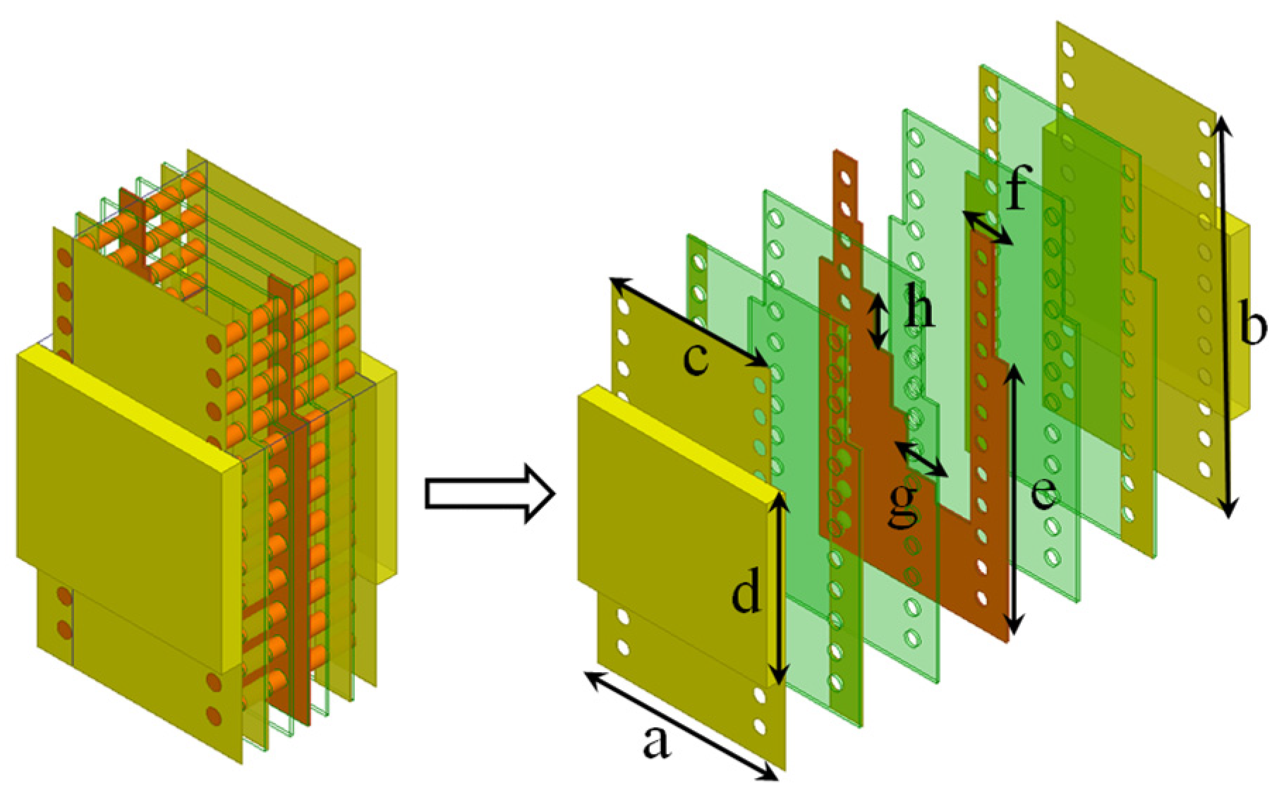
2.1. Antenna Unit Structure Design

A proposed antenna unit for circularly polarized wide-angle scanning phased array antennas in the millimeter-wave frequency range is depicted in Figure 1. The entire antenna unit utilizes SIW square waveguides and includes radiating square waveguides, circular polarizers, filters, and matching loads. The square SIW (depicted in yellow in Figure 1), which accommodates the circular polarizer (shown in orange in Figure 1), is situated in the upper portion of the antenna unit and is partitioned into two equal segments by the circular polarizer. Two flat SIWs (represented by blue and green sections in Figure 1) are positioned adjacently beneath the square SIW to supply the left and right segments of the square SIW, respectively. Various flat waveguide feeds enable distinct circular polarizations, facilitating the use of the same antenna configuration for both transmitting and receiving arrays. Moreover, matching loads are integrated at the terminations of the flat SIWs to mitigate cross-polarization effects, where no power feed is present.
Figure 2 illustrates the structure of the radiating square waveguide incorporating the circular polarizer. The metal structure of the waveguide is shown on the right side of the figure. The square radiating waveguide is divided into two sections filled with dielectric material with a relative permittivity of 2.94 and a loss tangent of 0.0025. The dielectric substrate material, with a relative permittivity of 3.28 and a loss tangent of 0.0024, surrounds this structure. The circular polarizer is positioned centrally within the square waveguide, forming left and right circularly polarized antenna radiating units using the SIW structure on each side. In an array configuration, the metal blocks on both sides can function as the antenna’s reflective metal plate.
In order to achieve better performance, the dimensional parameters of the radiating square waveguide structure are optimized. First, we optimize each individual component and make it have a good performance, at which point we can obtain the appropriate range of values for each parameter. Then, we optimize the overall structure and determine the value of each parameter. The optimized dimensional parameters are shown in Table 1, where the radius of the metal cylinder is r and the length is l.
To improve the antenna’s ability to suppress out-of-band signals, a bandpass filter is incorporated into the feeding flat SIW of the antenna unit, illustrated in Figure 3a. This filtering capability is achieved by integrating metal vias into the SIW structure, ensuring seamless integration without the need for standalone filters. This approach enhances overall system integration and supports a more compact design. The field distribution of the SIW filter structure is shown in Figure 3b. It can be seen that the vias effectively limit the radiation of electromagnetic waves to the external space, which enables the SIW filters to be integrated with various passive and active devices without the need for additional connector conversion.
To mitigate cross-polarization caused by reradiated waves, a matching load is integrated at the termination of the flat SIW without a power feed. This load absorbs electromagnetic waves reflected by the antenna. Figure 4 illustrates the structural configuration of the matching load. The buried resistor is depicted in red in the figure. The remaining blue part in the figure is the SIW structure. When electromagnetic waves enter from the top waveguide port, the matching load initially converts the waveguide mode into the coplanar waveguide (CPW) mode. Subsequently, it absorbs the electromagnetic waves using resistive films positioned on both sides of the CPW. In addition, the matching resistors are made using the PCB buried resistor process, which etches away the metal on the surface of the PCB to reveal the resistors that have been buried therein.
Combining all antenna components forms the complete antenna unit model. Figure 5 displays the structural model of the antenna unit from various viewpoints.

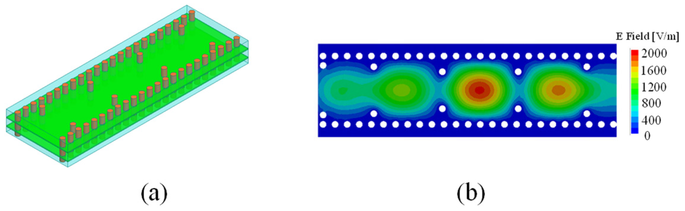
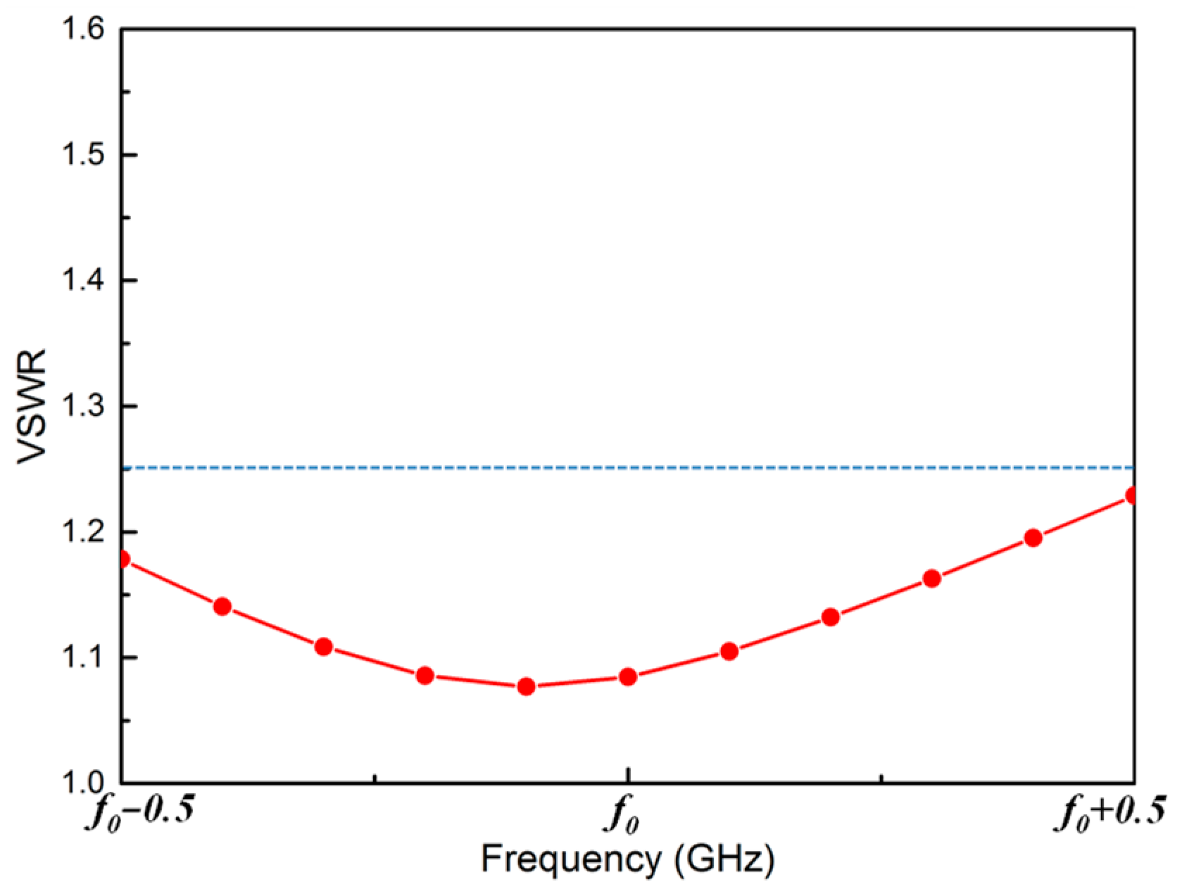
2.2. Analysis of Antenna Unit Performance

The antenna unit structure undergoes modeling in the three-dimensional electromagnetic simulation software ANSYS Electronics 2020 R1, where full-wave simulations assess both individual components and the overall antenna configuration. Initially, simulations focus on the electrical performance of the filter and matching load modules. Figure 6 presents the simulated electrical characteristics of the filter, demonstrating a voltage standing wave ratio (VSWR) below 1.11 within ±300 MHz around the center frequency, with an insertion loss of less than 0.57 dB. Beyond this range, up to ±500 MHz around the center frequency, performance shows a slight decline, with a maximum VSWR of 1.48 and an insertion loss below 0.8 dB.
By optimizing the coupling patch and the shape of the buried resistor in the matching load, a design achieving a VSWR of less than 1.25 across the entire bandwidth is achieved. Similar to the filter, the entire matching load is integrated into the SIW, eliminating the necessity for separate load devices. Consequently, the antenna’s volume and weight are reduced. Figure 7 illustrates the VSWR of the matching load.
Following the integration of all antenna components to form the complete antenna unit model, electromagnetic performance simulations are performed. The active VSWR performance of the antenna unit is depicted in the Figure 8a,b for angles θ = 0°, 20°, 40°, and 60°, with φ values of 0° and 90°.

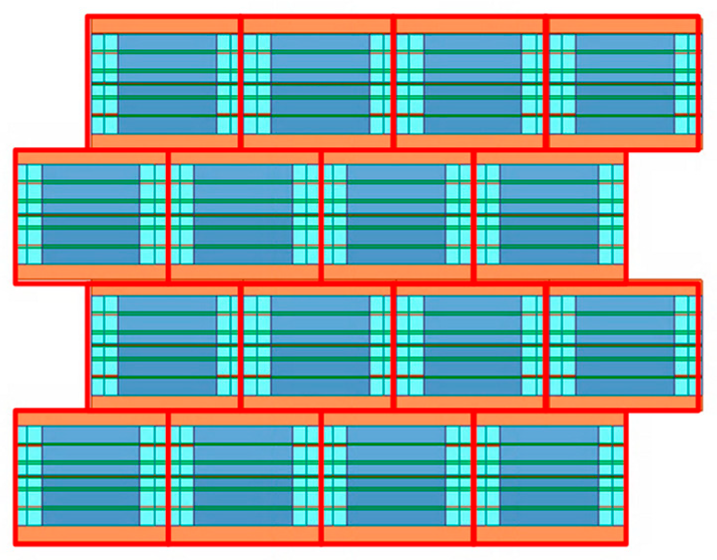
3. Two-Dimensional Wide-Angle Scanning Antenna Array

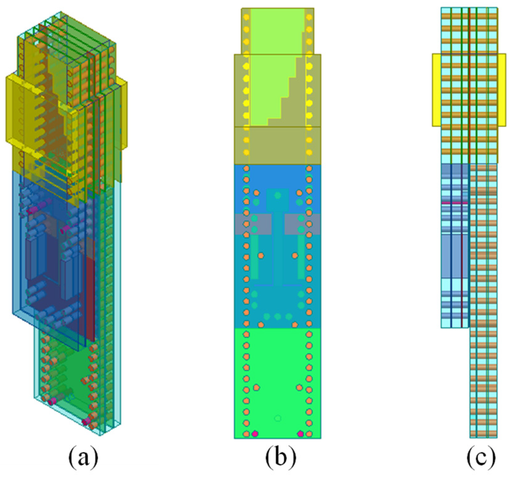
3.1. Antenna Array Design and Simulation Analysis

The previously described antenna unit serves as a fundamental component for the phased array antenna. A triangular grid configuration is implemented to expand the scanning capability of the phased array. The array consists of 16 (4 × 4) elements with inter-element spacings set to dx = 7 mm and dy = 6 mm. Figure 9 illustrates the layout of the array configuration. This is a top view of the antenna array, with a red box representing an antenna element.
Extensive modeling and full-wave simulations are conducted using HFSS to evaluate the beam scanning capabilities of the phased array formed by the antenna units. Figure 10 displays the gain characteristics at different scanning angles, centered around frequency f0 with a bandwidth of 1 GHz. The simulations indicate that the circularly polarized wide-angle scanning antenna achieves extensive phased scanning in both azimuth and elevation, spanning ±60° from the center frequency. At 0° scanning angle, the phased array antenna exhibits a gain of 15.9 dB. Within the antenna array’s scanning range, the reduction in gain is consistently below 3.9 dB.

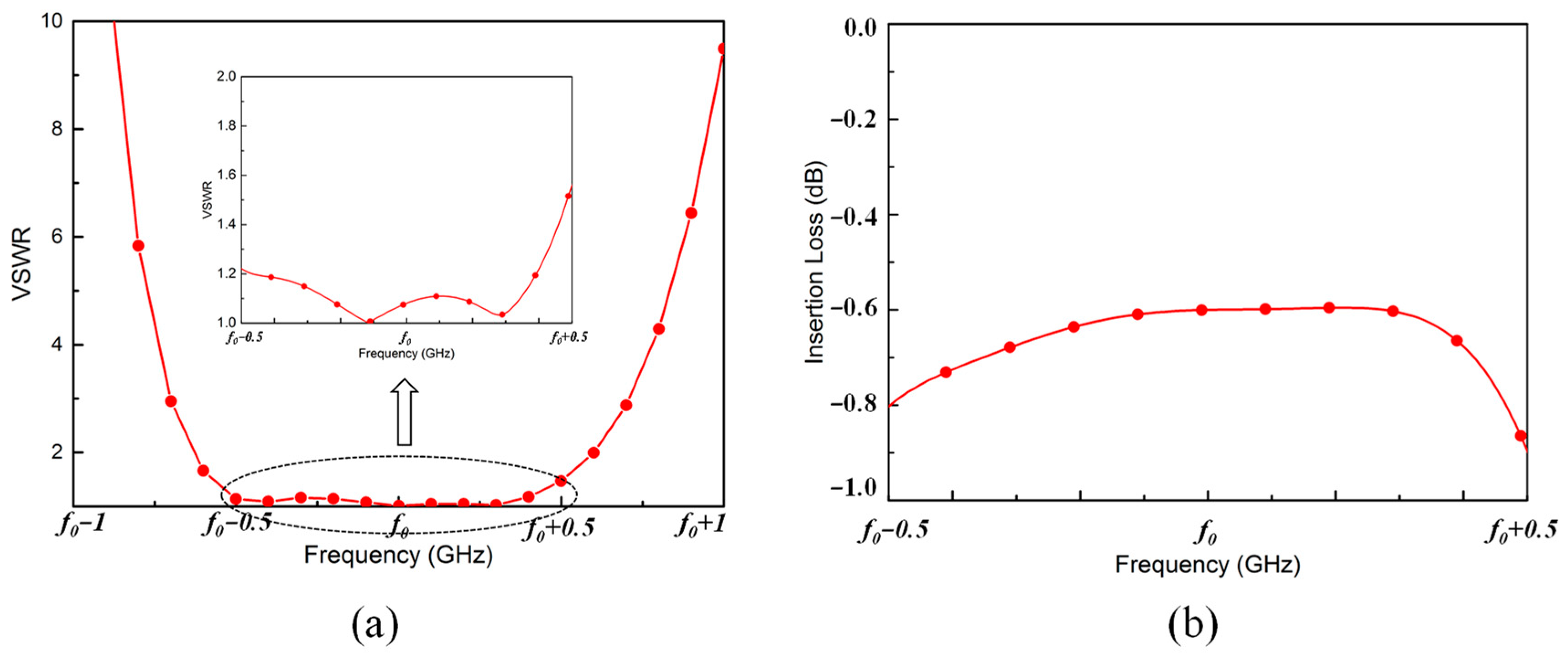
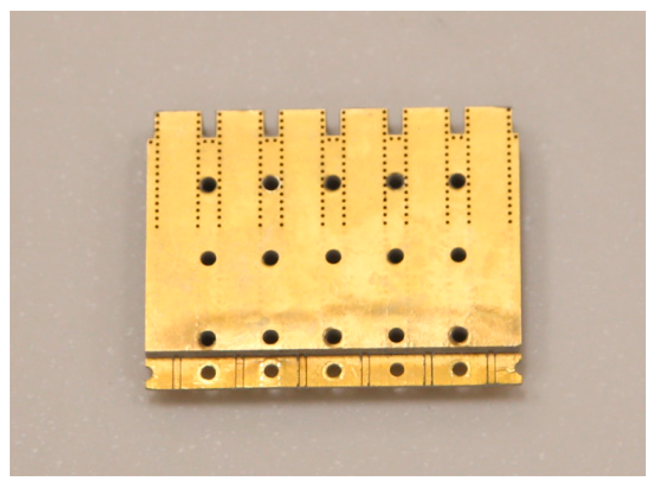
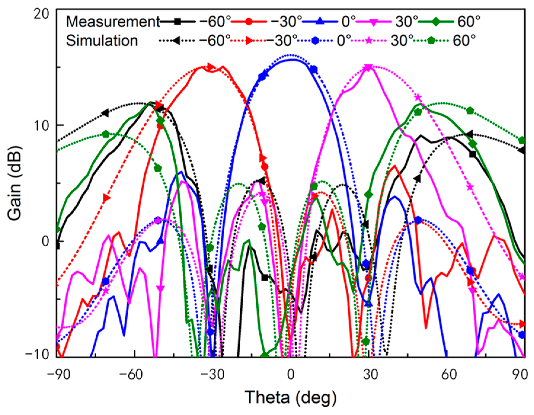
3.2. Measurement Results and Analysis

To verify the performance of the proposed antenna design, a SIW-based antenna array is manufactured using standard PCB fabrication methods. Figure 11 displays the fabricated antenna array, consisting of several antenna units. Testing is conducted in a planar near-field anechoic chamber equipped with a Keysight vector network analyzer. The gain characteristics at various scanning angles are depicted in Figure 12. By comparing the measured results with the simulation results, we can obtain the gain curves of simulation and measured comparison at different scanning angles, as shown in Figure 12. As can be seen from Figure 12, the circularly polarized wide-angle scanning antenna can achieve wide-angle scanning from −60° to +60° in azimuth and elevation at the operating frequency. The measured results are consistent with the simulation results. When the scanning angle is 0°, the gain of the phased array antenna test is 15.7 dB, which is 0.2 dB lower than the gain in simulation. When the antenna array scanning angles are ±30° and ±60°, respectively, the gain is basically consistent with the simulation results. In addition, when the theta is greater than 60°, the simulation and test curves are quite different, which is mainly due to the error of the test system when scanning at a large angle of the theta.

4. Conclusions

The SIW-based antenna unit combines circular polarizers, filters, and matching loads to achieve integrated design, strong out-of-band suppression, circular polarization, and wide-angle scanning capabilities. Utilizing PCB technology enables cost-effective mass production of the entire antenna unit. This innovation represents a new method for integrating millimeter-wave antennas and their components.

Author Contributions

Investigation, G.Y.; methodology, S.G.; validation, K.W.; writing—original draft preparation, G.Y.; writing—review and editing, S.G. and K.W.; supervision, J.X. All authors have read and agreed to the published version of the manuscript.

Funding

This research received no external funding.

Data Availability Statement

Data are contained within the article.

Conflicts of Interest

The authors declare no conflicts of interest.

References

  1. Herranz-herruzo, J.I.; Valero-nogueira, A.; Ferrando-rocher, M. Low-cost Ka-band switchable RHCP/LHCP antenna array for mobile SATCOM terminal. IEEE Trans. Antennas Propag. 2018, 66, 2661–2666. [Google Scholar] [CrossRef]
  2. Marzetta, T.L. Noncooperative cellular wireless with unlimited numbers of base station antennas. IEEE Trans. Wireless Commun. 2010, 9, 3590–3600. [Google Scholar] [CrossRef]
  3. Yang, S.J.; Pan, Y.M.; Shi, L. Millimeter-wave dual-polarized filtering antenna for 5G application. IEEE Trans. Antennas Propag. 2020, 68, 5114–5121. [Google Scholar] [CrossRef]
  4. Al-Samman, A.M.; Azmi, M.H.; Al-Gumaei, Y.A.; Al-Hadhrami, T.; Abd. Rahman, T.; Fazea, Y.; Al-Mqdashi, A. Millimeter wave propagation measurements and characteristics for 5G system. Appl. Sci. 2020, 10, 335. [Google Scholar] [CrossRef]
  5. Beiranvand, B.; Iyer, A.K.; Mirzavand, R. Cost-Effective design of a reflectarray antenna for 5G and millimeter-wave applications utilizing 3-D-printed components. Antennas Wirel. Propag. Lett. 2024, 23, 925–929. [Google Scholar] [CrossRef]
  6. Hong, W.; Jiang, Z.H.; Yu, C. Multibeam antenna technologies for 5G wireless communications. IEEE Trans. Antennas Propag. 2017, 65, 6231–6249. [Google Scholar] [CrossRef]
  7. Zhou, Z.P. Millimeter wave active phased array antenna technology. J. Microw. 2018, 34, 1–5. [Google Scholar]
  8. Li, J.H.; Li, Y.B.; Chen, Z.X.; Liu, P.Y.; Gu, X.J. Research on modularized millimeter wave phased array antenna. J. Microw. 2018, 34, 99–102. [Google Scholar]
  9. Cheng, L.; Wu, F.W.; Li, Y.J. Design of a broadband high-isolation and low-cost millimeter-wave antenna array unit. Modern Radar. 2022, 44, 79–83. [Google Scholar]
  10. Zhang, Y.P.; Liu, D. Antenna-on-chip and antenna-in-package solutions to highly integrated millimeter-wave decives for wireless communications. IEEE Trans. Antennas Propag. 2009, 57, 2830–2841. [Google Scholar] [CrossRef]
  11. Gu, X.; Liu, D.; Baks, C. Development, implementation, and characterization of a 64-element dual-polarized phased-array antenna module for 28-GHz high-speed data communications. IEEE Trans. Microw. Theory Technol. 2019, 67, 2975–2984. [Google Scholar] [CrossRef]
  12. Han, G. A novel hybrid phased array antenna for satellite communication on-the-Move in Ku-band. IEEE Trans. Antennas Propag. 2015, 63, 1375–1383. [Google Scholar] [CrossRef]
  13. Tang, H.; Hong, W.; Chen, J. Development of millimeter-wave planar diplexers based on complementary characters of dual-mode substrate integrated waveguide filters with circular and elliptic cavities. IEEE Trans. Microw. Theory Technol. 2007, 55, 776–782. [Google Scholar] [CrossRef]
  14. Cheng, Y.; Dong, Y.D. Wideband circularly polarized planar antenna array for 5G millimeter-wave applications. IEEE Trans. Antennas Propag. 2021, 69, 2615–2627. [Google Scholar] [CrossRef]
  15. Gan, Z.; Tu, Z.H.; Xie, Z.M. Compact wideband circularly polarized microstrip antenna arrayfor 45 GHz application. IEEE Trans. Antennas Propag. 2018, 66, 6388–6392. [Google Scholar] [CrossRef]
  16. Chen, L.; Zhang, T.; Wang, C.; Shi, X. Wideband circularly polarized microstrip antenna with wide beamwidth. Antennas Wirel. Propag. Lett. 2014, 13, 1577–1580. [Google Scholar] [CrossRef]
  17. Bao, X.L.; Ammann, M.J. Dual-frequency dual circularly-polarised patch antenna with wide Beamwidth. Electron. Lett. 2008, 44, 1233–1234. [Google Scholar] [CrossRef]
  18. Han, G.D.; Chen, K.; Yuan, J.D. A miniaturized circularly polarized antenna for Beidou navigation satellite system application. Modern Radar. 2017, 39, 64–77. [Google Scholar]
  19. Ta, S.X.; Park, I. Low-profile broadband circularly polarized patch antenna using metasurface. IEEE Trans. Antennas Propag. 2015, 63, 5929–5934. [Google Scholar] [CrossRef]
  20. Guntupalli, A.B.; Wu, K. 60-GHz circularly polarized antenna array made in low-cost fabrication process. Antennas Wirel. Propag. Lett. 2014, 13, 864–867. [Google Scholar] [CrossRef]
  21. Ren, F.; Hong, W.; Wu, K. Polarization-adjustable planar array antenna with SIW-Fed high-order-mode microstrip patch. IEEE Trans. Antennas Propag. 2017, 65, 6167–6172. [Google Scholar] [CrossRef]
  22. Hao, Z.; Liu, X.; Huo, X. Planar high-gain circularly polarized element antenna for array applications. IEEE Trans. Antennas Propag. 2015, 63, 1937–1948. [Google Scholar] [CrossRef]
  23. Liu, W.H.; Han, G.D. Design of right-handed circular-polarized non-resonant slotted waveguide antenna array. Modern Radar. 2022, 44, 84–88. [Google Scholar]
  24. Chen, A.; Zhang, Y.; Chen, Z. Development of a Ka-band wideband circularly polarized 64-element microstrip antenna array with double application of the sequential rotation feeding technique. Antennas Wirel. Propag. Lett. 2011, 10, 1270–1273. [Google Scholar] [CrossRef]
  25. Liu, C.; Guo, Y.X.; Bao, X. 60-GHz LTCC integrated circularly polarized helical antenna array. IEEE Trans. Antennas Propag. 2012, 60, 1329–1335. [Google Scholar] [CrossRef]
  26. Li, Y.; Luk, K.M. A 60-GHz wideband circularly polarized aperture-coupled magneto-electric dipole antenna array. IEEE Trans. Antennas Propag. 2016, 64, 1325–1333. [Google Scholar] [CrossRef]
  27. Liu, C.; Xiao, S.; Guo, Y.X. Broadband circularly polarized beam-steering antenna array. IEEE Trans. Antennas Propag. 2013, 61, 1475–1479. [Google Scholar] [CrossRef]
  28. Ouyang, J. A circularly polarized switched-beam antenna array. Antennas Wirel. Propag. Lett. 2011, 10, 1325–1328. [Google Scholar] [CrossRef]
  29. Yang, S.L.; Chair, R.; Kishk, A. Study on sequential feeding networks for subarrays of circularly polarized elliptical dielectric resonator antenna. IEEE Trans. Antennas Propag. 2007, 55, 321–333. [Google Scholar] [CrossRef]
  30. Wu, Q.; Wang, H.; Yu, C. Low-profile circularly polarized cavity-backed antennas using SIW techniques. IEEE Trans. Antennas Propag. 2016, 64, 2832–2839. [Google Scholar] [CrossRef]
  31. Li, W.M.; Liu, B.; Zhao, H.W. The U-shaped structure design in dual-band circularly polarized slot antenna. Antennas Wirel. Propag. Lett. 2014, 13, 447–450. [Google Scholar]
  32. Razavi, S.A.; Neshati, M.H. Low profile circularly polarized cavity backed antenna using HMSIW technique. In Proceedings of the 20th Iranian Conference on Electrical Engineering (ICEE2012), Tehran, Iran, 15–17 May 2012. [Google Scholar]
  33. Park, S.J.; Park, S.O. LHCP and RHCP substrate integrated waveguide antenna arrays for millimeter-wave applications. Antennas Wirel. Propag. Lett. 2017, 16, 601–604. [Google Scholar] [CrossRef]
  34. Hung, K.F.; Lin, Y.C. Novel broadband circularly polarized cavity-backed aperture antenna with traveling wave excitation. IEEE Trans. Antennas Propag. 2010, 58, 35–42. [Google Scholar] [CrossRef]
Figure 1. Schematic diagram of the SIW square waveguide.
Electronics 13 03328 g001
Figure 2. The structure of the radiating square waveguide incorporating the circular polarizer.
Electronics 13 03328 g002
Figure 3. (a) Model of the SIW filter structure. (b) The field distribution of the SIW filter structure.
Electronics 13 03328 g003
Figure 4. Model of the matching load structure.
Electronics 13 03328 g004
Figure 5. Model of the antenna unit structure from different perspectives: (a) Perspective; (b) Front view; (c) Side view.
Electronics 13 03328 g005
Figure 6. Electrical performance of the filter: (a) VSWR; (b) insertion loss.
Electronics 13 03328 g006
Figure 7. The VSWR of the matching load.
Electronics 13 03328 g007
Figure 8. The active VSWR for θ = 0°, 20°, 40°, and 60°: (a) φ = 0°; (b) φ = 90°.
Electronics 13 03328 g008
Figure 9. The illustration of the array layout.
Electronics 13 03328 g009
Figure 10. The simulation of the active radiation pattern at frequency f0 GHz.
Electronics 13 03328 g010
Figure 11. The fabricated antenna array.
Electronics 13 03328 g011
Figure 12. The comparison of simulated and measured results of the scanning pattern at the center frequency.
Electronics 13 03328 g012
Table 1. Dimensions of the radiating square waveguide structure (mm).
abcdefghrl
7.0012.655.905.958.950.800.551.620.244.62
Disclaimer/Publisher’s Note: The statements, opinions and data contained in all publications are solely those of the individual author(s) and contributor(s) and not of MDPI and/or the editor(s). MDPI and/or the editor(s) disclaim responsibility for any injury to people or property resulting from any ideas, methods, instructions or products referred to in the content.

