Article

Transient Synchronous Stability Analysis of Grid-Following Converter Considering Outer-Loop Control with Current Limiting

School of Electric Power Engineering, South China University of Technology, Guangzhou 510640, China
*
Author to whom correspondence should be addressed.
Electronics 2024, 13(16), 3337; https://doi.org/10.3390/electronics13163337
Submission received: 8 July 2024 / Revised: 14 August 2024 / Accepted: 20 August 2024 / Published: 22 August 2024

Abstract

:
With the evolution of modern power systems, inverter-based resources have become increasingly prevalent. As critical energy conversion interfaces, grid-following converters exhibit dynamic performances, presenting challenges for system security and stability. This paper focuses on the transient synchronization stability of converters after disturbances, highlighting differences in mechanisms compared to synchronous generators. Although previous studies on the transient synchronization stability of converters have been conducted, they primarily concentrate on the dynamics of the phase-locked loop, with limited consideration of the effects of outer-loop control. This has created a cognitive bottleneck in understanding the transient synchronization mechanisms of converters. To address these challenges, this paper models a grid-following voltage source converter system, incorporating detailed converter control strategies and current-limiting control. The stability regions of the stable equilibrium point under various fault severities are first analyzed. Then, the impacts of outer-loop control, including PI control and current-limiting control, on transient synchronization are examined. The study systematically elucidates the influence of outer-loop control on the transient synchronization stability of converters. Finally, the validity of the proposed theory is confirmed through simulations conducted in PSCAD/EMTDC.

1. Introduction

Primarily driven by environmental protection, greenhouse gas reduction, and sustainable development, renewable energy sources, such as wind and solar power have experienced rapid growth in recent decades. These sources typically employ converters as critical energy conversion interfaces, known as inverter-based resources (IBRs). IBRs have become increasingly integral to modern power systems and exhibit more complex dynamic performance compared to conventional synchronous generators. As a significant amount of renewable energy is connected to the grid through voltage source converters (VSCs), the control of these converters increasingly dominates system characteristics [1,2,3,4]. Conventional VSCs usually adopt grid-following (GFL) control, relying on a phase-locked loop (PLL), to achieve synchronization with the power grid [5]. Failure to achieve synchronization can impact the system, seriously affecting its safe and stable operation. For instance, in 2020, a 1000 MW renewable energy station in California, USA, experienced grid-connected interruption due to the synchronization instability of the converter after a disturbance [6].
Regarding the transient synchronization problem of GFL converters, previous studies have focused on PLL-based synchronization, achieving significant advancements in analysis models, mechanisms, and influencing factors [7,8,9,10,11]. However, these studies retain only the core components, overlooking potential interactions between different control loops of the converter [8]. For instance, [9] ignores the converter’s double-loop control structure and only considers the PLL to build a simplified synchronization model. A multi-converter system with multiple PLL models is established by considering multiple VSCs connected to the power grid [10]. Considering the nonlinear behavior of PLL, general sequential switching control schemes for the entire grid fault process are introduced to model the system [11]. The above work emphasizes the establishment and simplification of analysis models for GFL converters, providing a foundational model for studying the synchronization stability mechanism of voltage source converters (VSCs).
Existing studies on this topic often follow the framework used for transient synchronous stability analysis of synchronous generators [12,13,14,15,16,17,18]. By simplifying the converter and its control, researchers construct a second-order swing equation of the rotor angle, similar to that of synchronous generators, and use the equal area criterion to reveal the instability mechanism [12,13]. For example, the improved equal area criterion (IEAC) proposed in [12] offers an approximate calculation of the extra accelerating area caused by negative damping, reducing conservatism compared to Lyapunov methods. Based on the equal area criterion, [13] analyzes the effects of interactions among sequence-control switching actions, detection delay, and dual-sequence PLL control on the transient synchronous stability of the VSC system. Recently, some researchers have used phase portraits for fast discrimination of transient instability or have employed Lyapunov-based methods to estimate the region of attraction and characterize stability strength through changes in the stable region [14,15,16,17,18]. For instance, phase portraits have been used to describe the influence of different damping coefficients and initial angular speeds on the stability of GFL converters under inductive power grids [16]. Similarly, [17,18] uses phase portraits to analyze the impact of second-order equation damping ratios on the transient synchronization stability of converters. These studies provide an in-depth analysis of the PLL synchronization mechanism, establishing a theoretical basis for related research efforts.
In terms of understanding the influencing factors, existing studies focus on examining the effects of grid strength and investigating PLL parameter variations on transient synchronization characteristics [10,19,20,21]. These studies have helped to target the development of appropriate improvements. In [19], the impact of variations in grid voltage amplitudes, phases, and frequency on GFL synchronization stability following a large disturbance is studied. [10] proposes a feed-forward compensation method for PLL, thus improving the synchronization stability of the entire system. In [21], the indefinite damping effect and its impacts on the accuracy of the region of attraction estimated by the EAC method are revealed. During transient processes, retaining the proportional part of the PLL while locking the integral one can avoid overshoot and improve stability [20].
The above studies have explored the effects of grid strength conditions, PLL parameters, and structure on the transient synchronization of converters. However, as part of ongoing research into the mutual interaction between converters and grid, researchers have gradually realized that the low-order models, which only consider the PLL and ignore the dynamics of the double closed-loop control, often lose the details of the dynamic characteristics. This makes it difficult to fully explore the synchronization mechanism of converters under complex and variable scenarios, and the pathways of the various types of influencing factors cannot be fully identified [22,23,24].
The dynamic response speed of the outer-loop control in the GFL converter adopting a double closed-loop control structure is close to that of PLL, while the inner-loop control’s response is much faster than either the PLL or the outer-loop control [25]. Based on the multi-timescale separation decoupling theory, the inner-loop control can, thus, be neglected during the transient synchronous stability analysis [26]. Consequently, it is reasonable to retain both the outer-loop control and the PLL in such analyses. Furthermore, ref.[27] discusses the transient synchronization by considering the constant DC voltage outer-loop control. The study finds that increasing the proportional coefficient of the constant DC voltage control or decreasing the integral coefficient under slight faults can enhance system damping. However, a comprehensive analysis of the impact of different fault severity and control methods on transient synchronization stability is lacking.
It is also noted that current-limiting control is introduced in the GFL converter [28,29]. The current-limiting control is generally designed to maintain converter performance within acceptable bounds and to protect equipment from damage by preventing control signal overshoots, thereby ensuring safe and efficient operation. Under normal operating conditions, these nonlinear loops are not triggered. However, they may be frequently activated during the transient process following a disturbance. This activation can cause switching of control strategies, introducing unexpected effects on transient synchronization [30]. To address this issue, this paper incorporates the current-limiting control into the modeling and analysis of the transient synchronization stability of the GFL converter.
The main contributions of this paper are summarized as follows:
(1) By incorporating outer-loop control and PLL, a transient synchronization analysis model for VSC is developed. This model forms the basis for analyzing the effects of constant DC voltage outer-loop control, constant reactive power outer-loop control, and current-limiting control on VSC synchronization. The necessity of considering the outer-loop and current-limiting control, in addition to PLL, is emphasized in the transient stability analysis.
(2) For the first time, it is identified that under constant reactive power outer-loop control, severe grid fault can cause the voltage phasor at the point of common coupling (PCC) to shift to the negative half of the d-axis. This shift alters the PLL synchronization equation, thereby changing the stability region of the equilibrium point.
(3) Using equivalent circuit phasor diagrams, the transient synchronization characteristics of VSC with PI control and current-limiting control in outer-loop control are elucidated. The geometric representation of outer-loop control on phasor diagrams is provided and the impact of various outer-loop constraints on synchronization is analyzed. It is found that during severe fault, reducing the current saturation limit can enhance system stability when outer-loop control fully switches to current-limiting control.
The paper is structured as follows. Section 2 builds a transient synchronization analytical model for the converter, considering PLL and outer-loop control. Section 3 emphasizes the necessity of considering outer-loop control in transient stability analysis. Section 4 analyzes the variations in the transient synchronization of VSC under different degrees of grid fault severity, and comprehensively reveals the stabilization characteristics of the transient synchronization, including changes in the PLL synchronization equation, variations in the stable equilibrium point (SEP), and the impact of different outer-loop control systems on the transient synchronization of the converter. Section 5 verifies the proposed theory using PSCAD/EMTDC simulations, providing an in-depth physical explanation for the transient synchronization of VSCs.

2. Transient Synchronization Modeling of VSC

Figure 1 displays the GFL-VSC system. U g is the grid voltage, U PCC is the voltage of PCC, V dc is the DC voltage of the converter, I and Q are the current and reactive power injected into the grid by the converter, and L f denotes an L-type filter of the VSC. R g and L g represent the resistance and inductance of the grid, respectively. The Thévenin equivalent grid impedance is Z g = R g + j ω L g . The converter adopts outer-loop control strategies with constant DC voltage and constant reactive power, and it considers the current-limiting control. For a GFL converter, the response of the current control loop typically exhibits fast dynamics compared to other loops, such as the voltage control loop, and PLL. This separation in time scales allows for the assumption that the current loop reaches its quasi-state almost instantaneously compared to the slower dynamics of control loops. For most practical converter-based systems, the impact of neglecting the fast dynamics of the current loop on overall system performance is minimal [12]. This simplification aids in the control design and analysis, focusing on the dominant dynamics without significantly affecting system performance. Therefore, it can be assumed that I d I d * and I q I q * , where I d and I q are the d-axis and q-axis components of the output current I PCC in the converter control reference frame (dq reference frame), respectively.

2.1. Second-Order Synchronization Model of VSC

PLL is a crucial component in converters, particularly for grid-following applications, where synchronization with the grid voltage is essential. It outputs the reference phase and frequency by input PCC voltage U PCC , as shown in Figure 1. The dynamic equations of PLL are as follows:
d θ P L L d t = ω g + k ppll U PCCq + x int d x int d t = k ipll U PCCq
where ω g is the angular velocity of grid voltage, θ PLL is the PLL phase, x int is the PLL state variable, and k ppll and k ipll are the PLL proportional control coefficient and integral control coefficient, respectively.
Assuming normal operating conditions, after PLL locking, the direction of the PCC voltage phasor U ˙ PCC = U PCC δ coincides with the positive direction of the d-axis. The following relationship exists:
δ = θ PLL θ g = θ PLL 0 t ω g d τ
where θ g is the phase of the grid voltage phasor.
U PCC can be expressed as U PCC = R g I + j X g I + U g R g I * + j X g I * + U g . In the dq reference frame, the relationship between U PCC and U g can be written as follows:
U PCCd = R g I d * X g I q * + U g cos δ U PCCq = R g I q * + X g I d * U g sin δ
where U PCCd is the d-axis component of PCC voltage U PCC , and X g is the reactance of inductance at the grid frequency.
By substituting Equations (2) and (3) into (1), we can obtain the following:
d δ d t = k ppll ( U 0 U g sin δ ) + x int d x int d t = k ipll ( U 0 U g sin δ )
where U 0 = R g I q * + X g I d * is the q-axis component of the voltage drop in the transmission line.

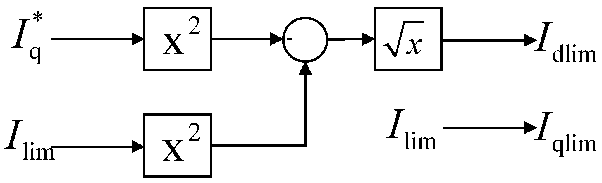
2.2. Outer-Loop Control of VSC

The outer-loop of the converter is controlled by constant DC voltage and constant reactive power, respectively. According to Figure 1, the following equation can be obtained:
d I d * d t = K pd d ( V dc V dc * ) d t + K id ( V dc V dc * ) d I q * d t = K pq d ( Q Q * ) d t + K iq ( Q Q * )
where K pd , K id , K pq , and K iq are the proportional-integral control coefficients of the outer loop, respectively.
As a power electronic device, the converter cannot withstand large overcurrent [22]. In contrast to the modeling work in [23], this paper incorporates the current-limiting control in the outer-loop control to ensure the safety of the converter. Common limiting strategies include the d-axis prior current limiting strategy and the q-axis prior current limiting strategy.
When employing the q-axis prior current limiting strategy, a constant converter current limit is set, prioritizing the satisfaction of the q-axis current reference to provide reactive power to the grid. The d-axis current reference is then calculated accordingly. On the other hand, adopting the d-axis prior current limiting strategy ensures preferential satisfaction of the d-axis current reference. This paper adopts the q-axis prior current limiting strategy, and the current-limiting control diagram is depicted in Figure 2. The corresponding expression is obtained as follows:
I qlim = I lim I dlim = I lim 2 I q 2 I q * I qlim I d * I dlim
where I qlim and I dlim are the limiting amplitudes of I q * and I d * , respectively. In this paper, the current saturation limit I lim is set at 1.2 p.u.
The essence of constant DC voltage control lies in ensuring a steady DC voltage output tailored to the specific requirements of applications. Once the output active power and input active power are balanced, the DC voltage remains stable. The variations in the DC voltage are primarily managed by the charging and discharging function of the DC capacitor, balancing the input and output power of the converter. Neglecting the losses in the transmission line and the converter, the principle of energy conservation can be expressed as follows:
C V dc d V dc d t = P dc * P dc , P dc = P = I d V PCCd + I q V PCCq
where P dc , P dc , and P are the input active power on the DC side, the output active power on the DC side, and the output active power on the AC side, respectively. V dc is the voltage of the converter’s DC capacitor. It can be observed that P = P dc during normal operation.

3. The Necessity of Considering Outer-Loop Control

A large number of studies have simplified the modeling in the transient synchronous stability analysis of VSC, as they primarily consider the dynamics of PLL [8,9]. An accepted assumption is that the current reference values are constant. Thus, U 0 remains constant during the transient process due to U 0 = R g I q * + X g I d * . A second-order synchronous model is used for analysis, as shown in Equation (4). Equation (4) is similar to the mathematical description for the rotor motion of a synchronous generator, where U 0 and U g sin δ can be analogized to the converter control component and the grid electrical component in the VSC synchronization equation, respectively.
At the equilibrium point, the differential terms in Equation (4) are equal to 0. It is easy to obtain d δ d t = 0 and d x int d t = 0 . Then, U 0 = U g sin δ and x int = 0 can be derived. Without the loss of generality, assuming that the operation range of δ is π , π , in order to ensure that U 0 = U g sin δ holds, the criterion for the existence of an equilibrium point for the VSC will be as follows:
U g U 0 U g , δ π , π
In this way, two equilibrium points will also exist for VSC when the inequality (8) is satisfied, similar to the transient synchronization analysis of synchronous generators. The equivalent synchronous coefficient S Eq can be used to further distinguish between stable and unstable equilibrium points, as follows:
S Eq = d ( U g sin δ ) d δ = U g cos δ
The stable criterion for the SEP is as follows:
S Eq > 0
Inequality (10) is only valid if the equilibrium point satisfies δ π 2 , π 2 . The equilibrium point within this region is a SEP, and the larger the value of S Eq , the greater the ability to remain stable.
A three-phase short-circuit fault represents one of the most severe fault conditions that can occur in a power system, leading to drastic changes in grid voltage levels and posing substantial risks to system stability and the continuous operation of sensitive electrical equipment. While other disturbances, such as single-phase-to-ground or phase-to-phase faults, also impact power systems, their effects are generally less severe than those of a three-phase fault.
Using a three-phase grid voltage dip to simulate a three-phase short-circuit fault is a common simulation technique in power system analysis. This approach allows for an accurate representation of the fault’s impact on system dynamics by modeling the associated voltage reduction. The severity of the fault is reflected in the magnitude of the voltage dip, which can be adjusted to represent different fault conditions. For instance, the depth of the voltage dip can vary depending on various factors, such as grounding impedance and the electrical distance between the fault location and the system under study. These variations in fault severity are crucial for assessing the robustness of system components, particularly in the context of VSCs and other power electronic devices, which are becoming increasingly prevalent in modern power systems.
After the disturbance, it is assumed that the grid voltage falls to U g . At this point, the SEP changes from point a to point b, as shown in Figure 3. The red area represents the feasible region of δ when the equilibrium point isa a SEP ( δ π 2 , π 2 ).
After the SEP is identified, existing studies often utilize the equal area criterion to analyze the transient synchronization stability of VSCs [12,13]. If U 0 > U g sin δ , the angular frequency of PLL will accelerate. Conversely, if U 0 < U g sin δ , the angular frequency of PLL will decelerate. Thus, when the angular frequency of PLL can be restored to the grid angular frequency ω g after disturbance, the VSC satisfies the transient synchronization stability; otherwise, the VSC will experience transient synchronization instability.
Following the idea of analyzing the transient synchronization of synchronous generators, the aforementioned analytical study effectively captures the dynamics of the system and clarifies the physical concepts. However, certain differences arise when applied to VSCs. Unlike in synchronous generators, where mechanical torque is typically assumed to remain unchanged, the reference current in VSCs varies with the regulation of the outer-loop control during the transient process.
In reality, complex dynamic behaviors emerge due to varying degrees of fault severity. When the fault severity is slight, the reference current is influenced only by the constant DC voltage control and constant reactive power control where PI control regulates signals. In contrast, under severe fault conditions, outer-loop control switches, and the current-limiting control can dominate the transient process. There may even be multiple control strategy switches during the transient process, leading to changes in U 0 .
This demonstrates the unique characteristics of the transient synchronization of VSCs compared with synchronous generators. Consequently, calculating acceleration/deceleration areas and determining the SEP becomes more complex. If the traditional second-order PLL model is adopted without considering the outer-loop control and current-limiting control, the analysis results will be inaccurate or erroneous. Therefore, it is necessary to incorporate the effect of the outer-loop control and current-limiting control in the transient synchronous stability analysis of VSCs.

4. Synchronous Stability of VSC Considering Outer-Loop Control

VSCs rely on PLL to establish the dq reference frame, enabling seamless integration with the grid. As shown in Figure 1, deviations arise between the outer-loop control variables and their references. These deviations are fed into the PI control and current-limiting control, ultimately generating the required d-axis and q-axis reference currents. Notably, during transients caused by external factors or control strategy adjustments, the outer-loop control plays a crucial role in shaping the transient response by influencing the output values. This section delves into the impact of outer-loop control on VSC’s transient synchronization following a three-phase short-circuit fault simulated by a grid voltage drop. Using the model established in Section 1, we systematically analyze three key aspects: the change in the PLL synchronization equation during a fault, the change in SEP, and the control constraints.

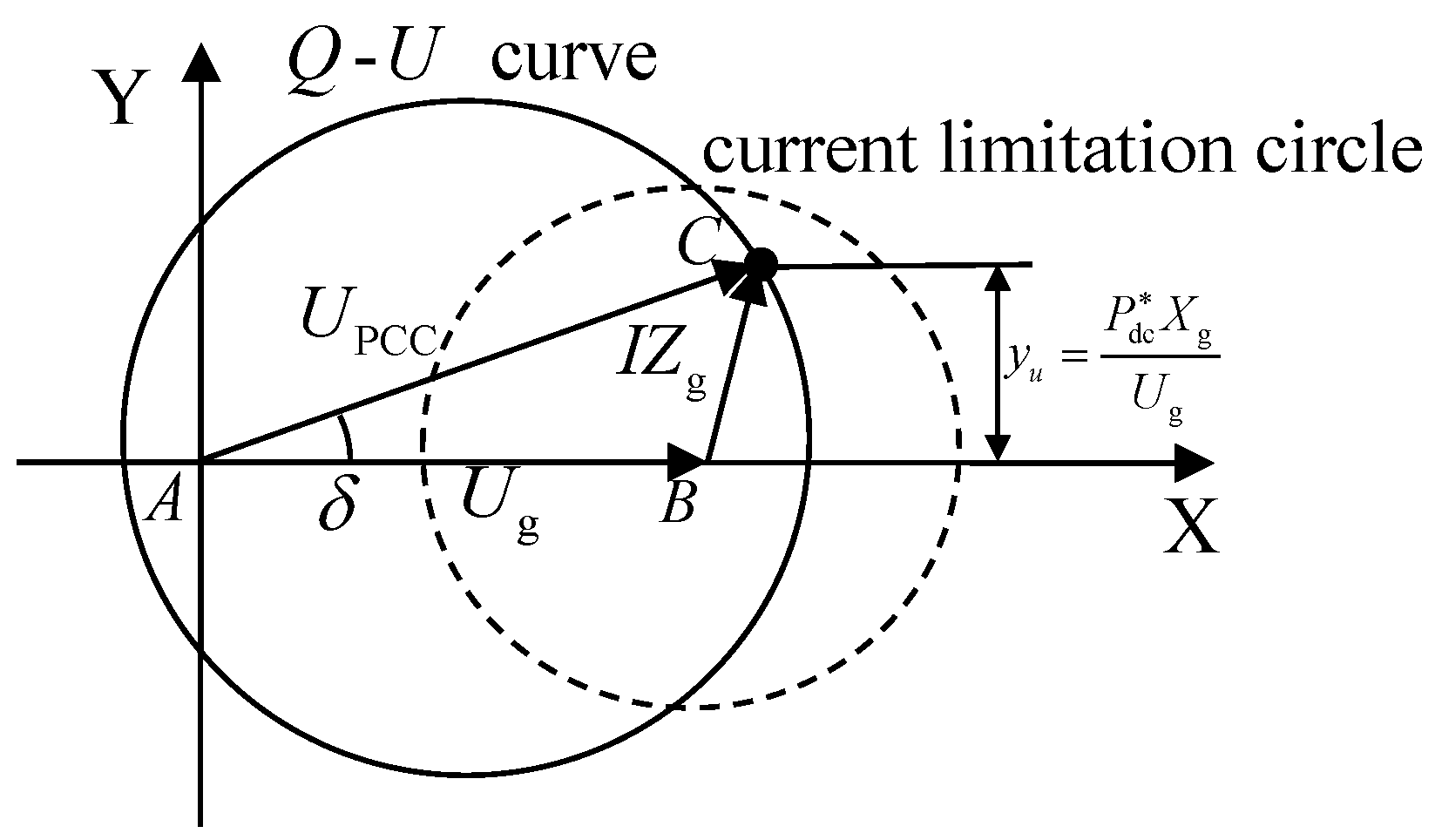
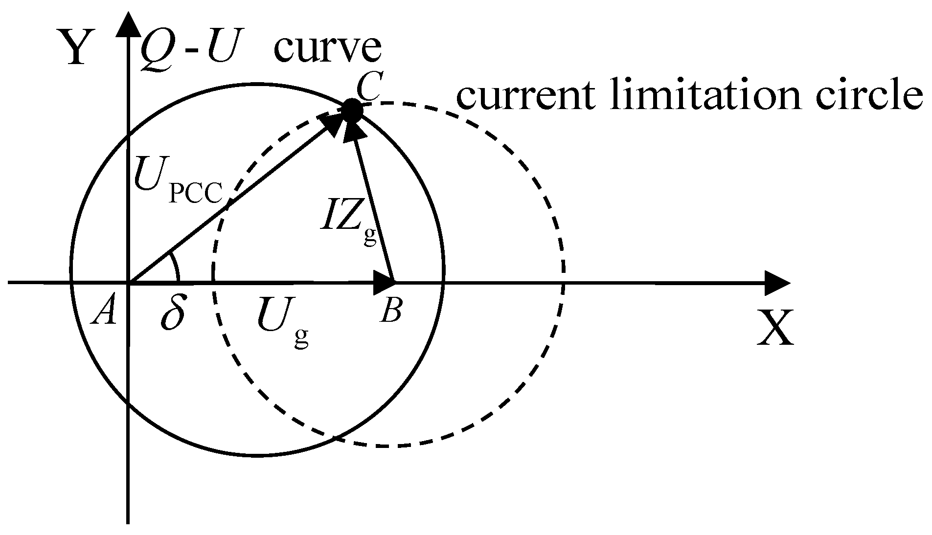
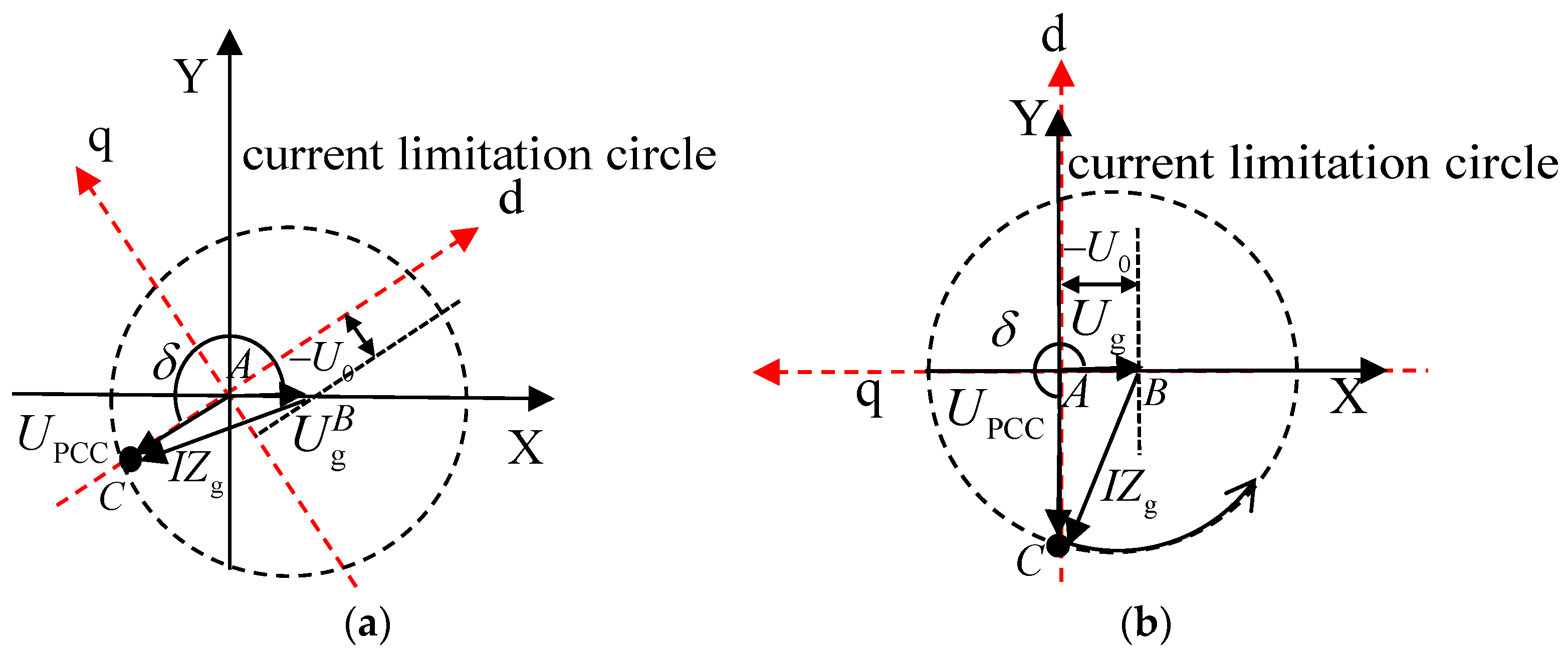
4.1. Synchronization Equation of PLL

Under normal operating conditions, the PCC voltage phasor U ˙ PCC = U PCC δ aligns with the positive d-axis direction after PLL synchronization, resulting in U PCCq = 0 . In this case, the PLL synchronization equation is Equation (4). The reactive power delivered by VSC to the grid can be expressed as follows:
Q = I q * U PCCd + I d * U PCCq = I q * U PCCd
The q-axis outer-loop of VSC typically employs constant reactive power control. This strategy necessitates delivering inductive reactive power to the grid (i.e., Q > 0) during normal operation. It is necessarily required that I q * < 0 when U PCCd > 0 . However, according to the grid operation code, the VSC output Q will be required to increase when the system is subjected to rapid voltage dips caused by severe disturbances. The q-axis outer-loop of the VSC, employing constant reactive power control, can lead to an increase or even a reversal in the output Q . This can also cause I q * to switch from negative to positive values. If the VSC remains synchronized with the grid after disturbance, it can maintain a certain amount of reactive power output. As seen from Equation (11), U PCCd will correspondingly shift from positive to negative, which means that the PCC voltage moves to the negative d-axis. The phase changes during the above process are illustrated in the grid coordinate (XY reference frame, rotating at the nominal angular frequency) and in the control coordinate of VSC (dq reference frame, rotating at PLL angular frequency), as shown in Figure 4.
Accordingly, the PLL synchronization equation changes from Equation (4) to the following Equation (12):
d δ d t = k ppll ( U 0 + U g sin δ ) + x int d x int d t = k ipll ( U 0 + U g sin δ )

4.2. SEP Analysis

When there is a severe dip in grid voltage, the PLL synchronization equation is given by Equation (12). The criterion for the SEP of the VSC is still governed by Equation (9). Here, it can be as follows:
S Eq = d ( U g sin δ ) d δ = U g cos δ
Thus, Equation (10) holds when the equilibrium point is satisfied. The equilibrium point within the region is stable.
After a fault, it is assumed that the grid voltage drops from U g to U g . Following adjustments by the outer-loop control, U 0 changes to U 0 , leading to three potential scenarios for the change in SEPs. (1) If the grid voltage drop does not alter the PLL synchronization equation, a SEP must exist, and its region remains δ π 2 , π 2 . The SEP shifts from point a to point c. (2) If a severe grid voltage drop alters the PLL synchronization equation, and the system satisfies inequality (8), a SEP exists, and its region becomes δ π , π 2 π 2 , π . The SEP shifts from point a to point c. (3) If a severe grid voltage drop alters the PLL synchronization equation, and the system does not satisfy the inequality (8), no SEP exists after the disturbance. The three scenarios of the system’s SEP changes following a grid voltage drop are illustrated in Figure 5. The red area represents the feasible region of δ when the equilibrium point is a SEP, which corresponds to δ π 2 , π 2 , δ π , π 2 π 2 , π and δ π , π 2 π 2 , π respectively in Figure 5a, Figure 5b and Figure 5c.

4.3. Effect of Outer-Loop Control on the Synchronization Process

Due to U 0 = R g I q * + X g I d * , and the output of the outer-loop control of the converter being I d * and I q * , it means that U 0 is closely related to the converter control and is highly influenced by the various control links and corresponding parameters in the outer-loop control. The action response of the outer-loop control of the converter varies under different operating conditions. U 0 is affected both by changes in the reference current through the PI control and may be limited by the current-limiting control, thus presenting a complex transient synchronization process. The following section will delve deeper into the transient synchronization stability of the VSC, considering the impact of PI control and current-limiting control in the outer-loop. We will utilize an equivalent circuit phasor diagram to aid in this explanation.
In the XY reference frame, point A denotes the common origin for both the PCC voltage phasor U ˙ PCC and the grid voltage phasor U ˙ g . Points B and C are the endpoints of U ˙ g and U ˙ PCC , respectively. The coordinates of point C at the end of the PCC voltage phasor U ˙ PCC are ( x U , y U ) . Thus, the magnitude of the PCC voltage can be expressed as U PCC = x U 2 + y U 2 . The corresponding voltage locus is a circle centered at point A with a radius equal to U PCC .
(1)
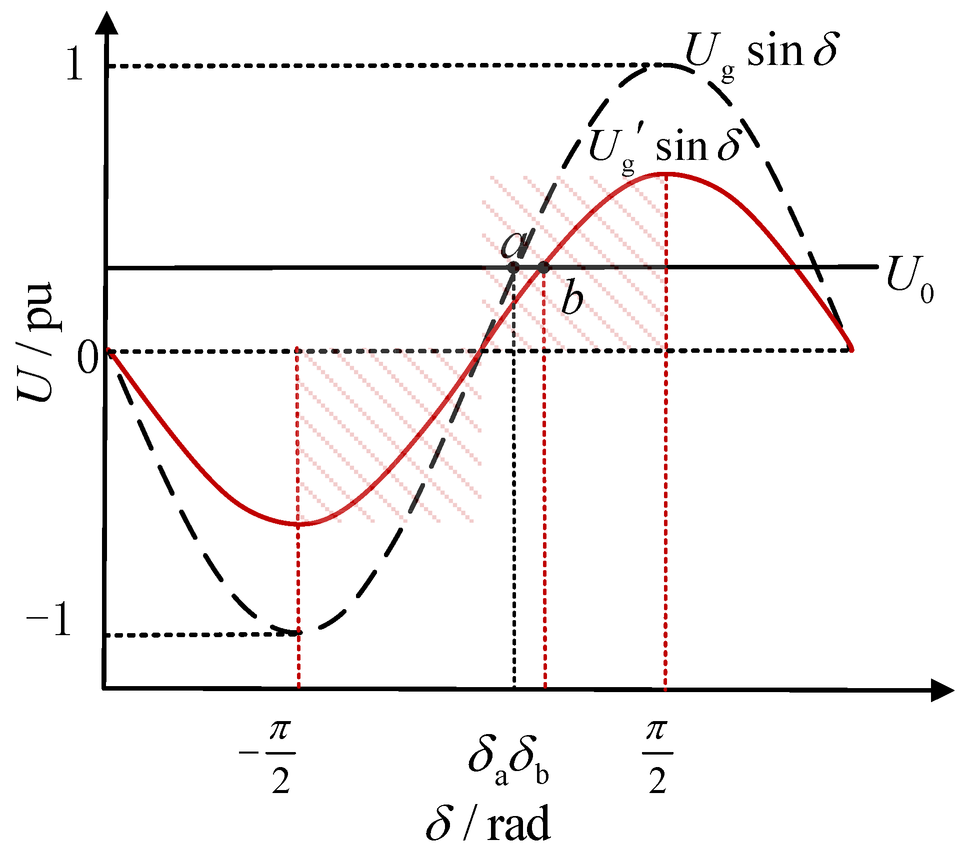
Slight drop in grid voltage
When there is a slight dip in the grid voltage, the outer-loop control of VSC generally does not trigger current-limiting control. The converter can continue to regulate its output based on the predefined control objectives. In such cases, the d-axis control maintains a steady DC voltage, ensuring that the power balance is preserved, while the q-axis control manages the reactive power to stabilize the voltage at PCC. Under these conditions, the VSC operates within its normal control parameters, allowing for smooth and stable transient synchronization without the need for additional intervention from the current limiter.
The following equation can be obtained:
U 0 = X g I d * + R g I q * = X g K pd ( V dc V dc * ) + K id ( V dc V dc * ) d t + R g K pq ( Q Q * ) + K iq ( Q Q * ) d t
Based on Equation (14), U 0 changes with the changes in V dc and Q . Meanwhile, V dc is also affected by P . Therefore, a further analysis of active and reactive power characteristics is needed.
The output active power of VSC can be expressed as follows:
P = U PCC X g U g sin δ = U g X g y U
When V dc is made constant by d-axis outer-loop control, P = P dc holds. A further simplification of Equation (15) is made as follows:
y U = P dc X g U g
It can be seen that when the d-axis outer-loop of VSC is controlled by a constant DC voltage, both U g and X g are constant, and the ordinate of point C remains constant.
Similarly, the output reactive power of VSC can also be expressed as follows:
Q = U PCC 2 X g U PCC U g cos δ X g = x U 2 + y U 2 X g U g x U X g
The above equation can be rewritten as follows:
x U U g 2 2 + y U 2 = X g Q + U g 2 4
It can be seen that once the q-axis outer-loop of VSC adopts constant reactive power control, and that U g and X g are both constant, the characterization of reactive power ( Q U curve) is a circle with a center as ( U g 2 , 0 ) and a radius as X g Q + U g 2 4 , as shown in Figure 6. After a disturbance, the VSC will continuously adjust the value of δ so that point C will eventually stabilize at the intersection of the Q U curve and the horizontal line y = P dc X g U g .
(2)
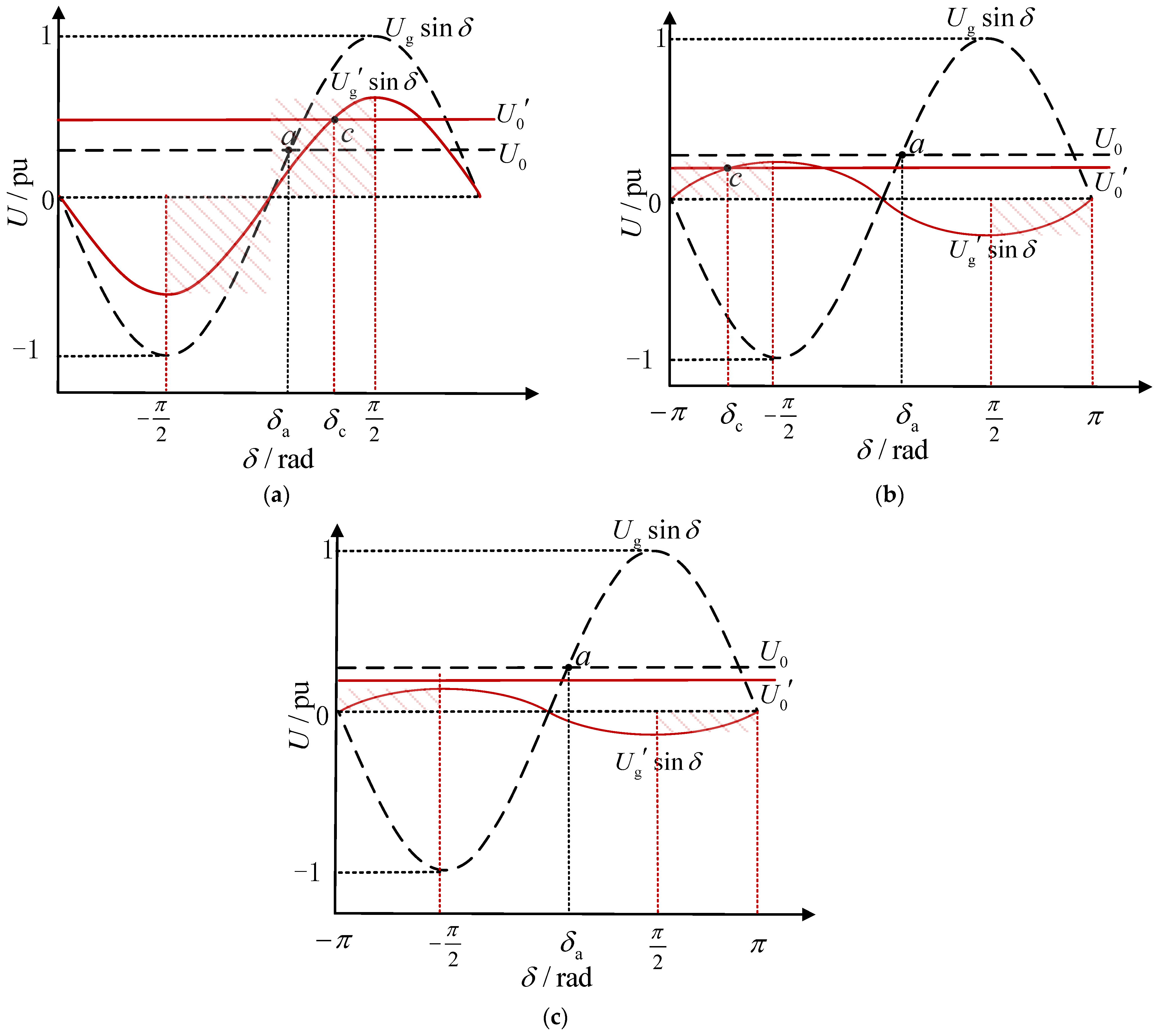
Moderate drop in grid voltage
When there is a moderate dip in grid voltage, the d-axis outer-loop control of the VSC generally triggers the current-limiting control, while the q-axis outer-loop of the VSC maintains constant reactive power control due to the q-axis prior current limiting strategy. If the grid voltage dips are relatively shallow, it is likely that the outer-loop of the VSC will eventually revert to PI control, consistent with the stabilization behavior observed during slight voltage drops described earlier. However, in the case of relatively deep grid voltage dips, the d-axis outer-loop remains in current-limiting control mode. Under these circumstances, the following equation can be derived:
U 0 = X g I d * + R g I q * = X g I lim 2 K pq ( Q Q * ) + K iq ( Q Q * ) d t 2 + R g K pq ( Q Q * ) + K iq ( Q Q * ) d t
It can be seen that U 0 will change with the variation in Q . Additionally, the current-limiting control will alter the synchronization characteristics of the VSC. When the current-limiting control is triggered, point C will remain on the current limiting circle centered at point B and with a radius of | Z g | I lim . Since the d-axis outer loop is controlled by current limiting, the balance of active power will be assisted by the unloading circuit connected in parallel with the DC capacitance, and point C is not constrained by active power. As shown in Figure 7, after disturbance, the VSC will continuously adjust the value of δ , so that point C ultimately stabilizes at the intersection of the Q U curve and the current limitation circle.
(3)
Severe drop in grid voltage
During severe grid voltage dips, both the d-axis and the q-axis outer-loop controls of VSC adopt the current-limiting control. Under these conditions, the following equation can be obtained:
U 0 = X g I d * + R g I q * = I lim R g
where U 0 becomes a constant, solely dependent on the current saturation limit I lim and grid impedance. Therefore, point C is no longer constrained by active power and reactive power, and its location is determined by the current limit circle and U 0 . According to the analysis in Section 4.1, the PCC voltage will be located in the negative half of the d-axis, i.e., δ = π + θ PLL θ g . As shown in Figure 8, after a disturbance, point C will quickly reach the current limiting circle for circular motion. If U g > U 0 , δ will be continuously adjusted by VSC to make the system finally satisfied, i.e., U g sin δ = U 0 . The existing literature has already addressed whether the VSC can stabilize at U g sin δ = U 0 by using methods, such as the energy function method or the equal-area criterion [12,14], which will not be repeated in this paper. If U g U 0 , it is not possible to achieve U g sin δ = U 0 . VSC will cause δ to keep increasing, which in turn makes point C move circularly along the current limitation circle, leading to synchronization instability.
The value of I lim is typically determined by converter components. Traditionally, the goal is to maximize converter efficiency and active/reactive power support during disturbances. Therefore, a larger I lim is generally preferred within economic and safety constraints.
However, a smaller U 0 is beneficial for transient synchronization stability under severe grid voltage dips. As evident from Equation (20), under constant grid resistance, U 0 depends on the current saturation limit I lim , i.e., the smaller the value of I lim , the better the transient synchronization stability of VSC. Thus, reducing I lim improves the transient synchronization stability of the VSC during severe dips in grid voltage.
In summary, the outer-loop control profoundly influences the transient synchronization process of the VSC, rendering the synchronization mechanism more complex compared to synchronous generators. To succinctly summarize the conclusions of this section, Table 1 is provided below.

5. Case Study

In order to verify the correctness of the described transient synchronous stabilization process of VSC, an electromagnetic transient model of the VSC grid-connected system is constructed in PSCAD/EMTDC, and the aforementioned synchronous stabilization mechanism is verified through time domain simulation. The relevant parameters are shown in Table 2.

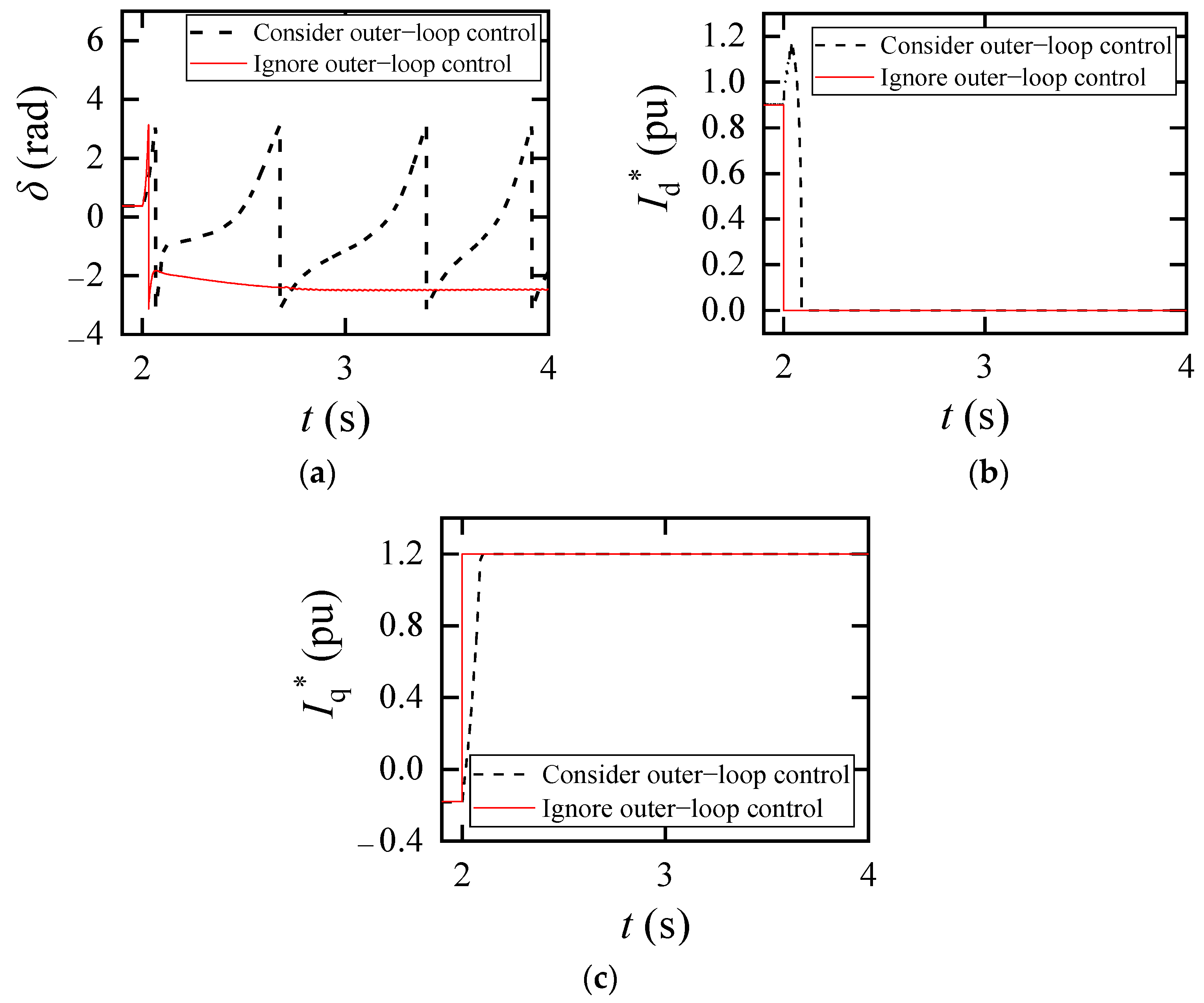
5.1. Impact of Outer-Loop Control on the Transient Synchronization Stability of VSC

The initial conditions are set as follows. The grid voltage is stabilized at 1.02 pu, and the VSC is synchronized with the grid, δ = 0.37 rad . The grid voltage is then reduced to 0.15 pu to simulate the disturbance. Two scenarios are simulated for comparison: one considering outer-loop control and the other ignoring outer-loop control (where I d * = I dlim = 0   pu , I q * = I qlim = 1.2   pu after the disturbance). The simulation results are shown in Figure 9.
Figure 9 shows that when outer-loop control is ignored, the VSC eventually regains stability, whereas in the actual system, the VSC ultimately experiences transient instability. In reality, the fluctuation amplitude of the electrical state variables during the transient process is greater than the result predicted when outer-loop control is ignored, leading to the VSC losing synchronization after the disturbance. This result indicates that using the second-order model, which has been the focus of existing studies [12,14], to analyze the transient synchronization stability of the VSC may lead to discrepancies with the actual situation and potentially erroneous conclusions. Even if the current reference values of the two models are the same before and after the disturbance (before the disturbance: I d * = 0.90   pu , I q * = 0.18   pu ; after the disturbance: I d * = I dlim = 0   pu , I q * = I qlim = 1.2   pu ), the regulation of outer-loop control during the transient process makes the VSC’s transient characteristics more complex.
Next, the impact of disturbances with varying severity on the transient synchronization stability of the VSC will be further verified. The influence of varying degrees of grid voltage dips on VSC synchronization stability is investigated through simulations. The grid voltage is set to drop to 0.9 pu (a slight dip in grid voltage), 0.6 pu (a moderate dip in grid voltage), 0.3 pu (a severe dip in grid voltage), and 0.1 pu (a severe dip in grid voltage) at t = 2 s , which are referred to as Scenario 1, Scenario 2, Scenario 3, and Scenario 4, respectively.

5.2. Changes in SEP

Figure 10 presents the waveforms of I q * , I d * , U 0 , and δ following the system disturbance. After obtaining the simulation results, in order to clearly highlight the differences in the transient characteristics of the VSC under different conditions, the results are categorized and presented based on whether I q * is less than 0. Figure 10a demonstrates how the outer-loop control of the VSC influences the SEP when I q * < 0 , while Figure 10b illustrates SEP variations when I q * > 0 .
As shown in Figure 10a, when the grid voltage drops to 0.9 pu (Scenario 1) and 0.6 pu (Scenario 2), respectively, I q * transitions to a higher value | I q * | after fluctuations, and still satisfies the condition of I q * < 0 . Therefore, it will not alter the PLL synchronization equation. After experiencing fluctuations, I d * exhibits a certain degree of increase. The changes in I q * and I d * result in the variation in U 0 . After fluctuations, U 0 stabilizes at a value higher than its initial value. The PCC phase angle undergoes acceleration and deceleration processes, eventually stabilizing at δ = 0.49 rad and δ = 0.89 rad , respectively. The SEP remains within the range of δ π 2 , π 2 , consistent with the earlier discussion regarding SEP behavior during slight and moderate voltage dips.
However, during severe voltage dips, SEPs exhibit different behavior. As shown in Figure 10b, when the grid voltage drops to 0.3 pu (Scenario 3) and 0.1 pu (Scenario 4), I q * reaches the current saturation limit of 1.2 pu after fluctuations, and I q * > 0 . This change alters the PLL synchronization equation. Once I q * stabilizes at its saturation limit, I d * also stops changing. Due to the q-axis prior current limiting strategy, I d * = 0 . The constancy of I q * and I d * maintains U 0 at 0.1 pu. In Scenario 3, the PCC phase angle undergoes acceleration and deceleration processes, eventually stabilizing at δ = 2.90 rad , with the SEP within the range of δ π , π 2 π 2 , π , which differs from the SEP behavior in Scenario 1 and Scenario 2. In Scenario 4, the system lacks a SEP due to U g = U 0 . As a result, the converter ultimately fails to restore synchronization stability.

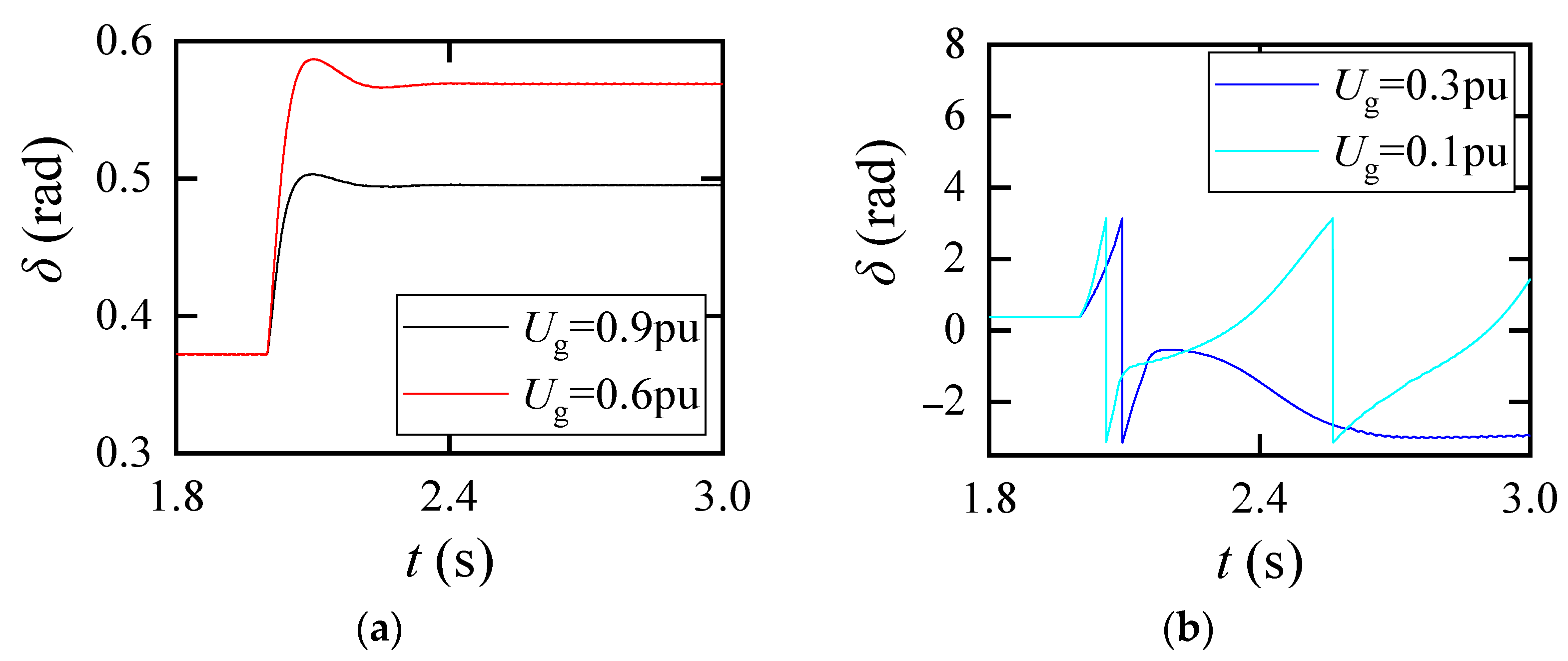
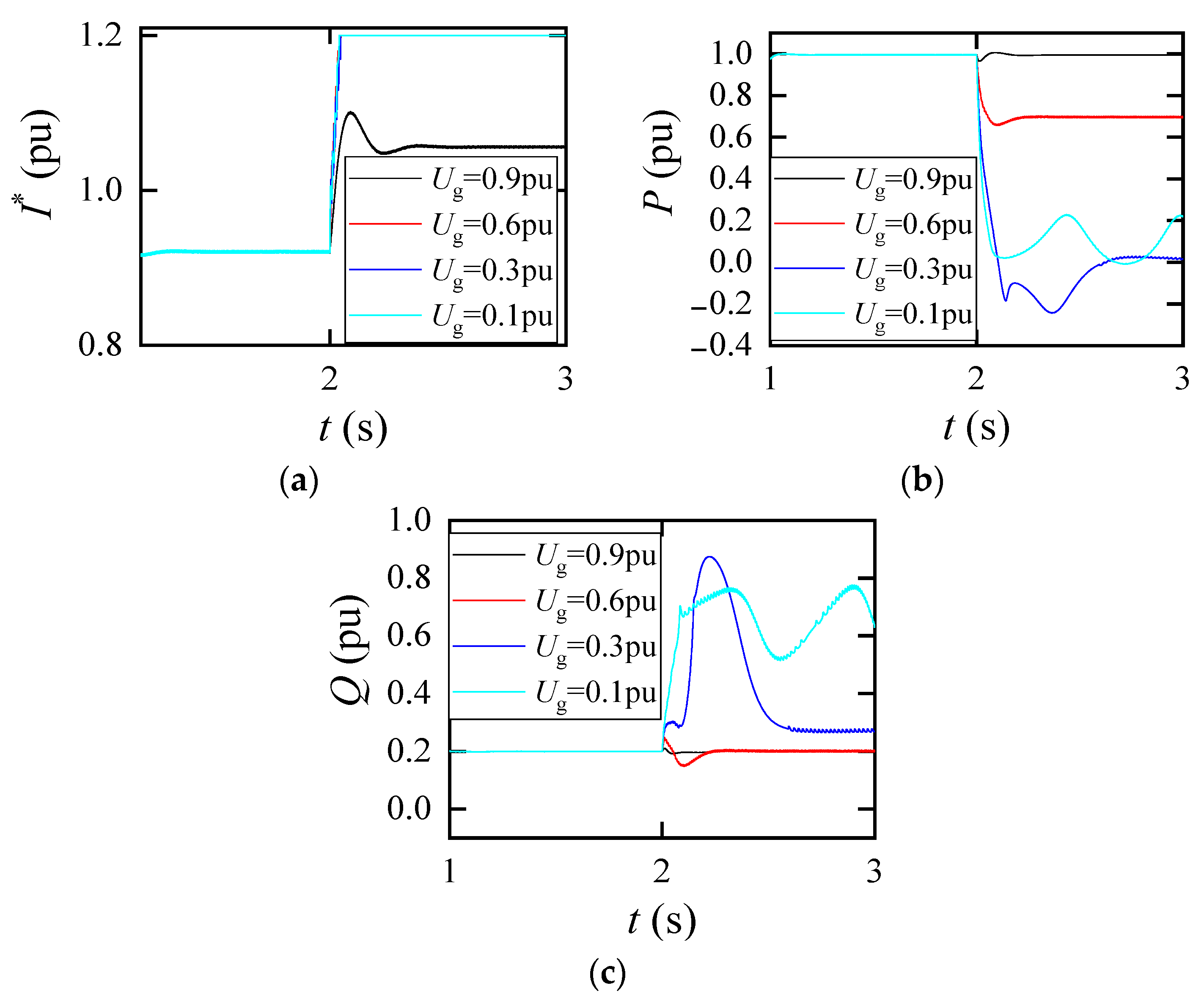
5.3. System Dynamics Considering Outer-Loop Control

From the aforementioned analysis, it can be concluded that in Scenarios 3 and 4, both the d-axis outer-loop control and q-axis outer-loop control of the VSC employ current-limiting control. However, from Figure 10a, it is not possible to determine whether current-limiting control is activated in Scenarios 1 and 2. Figure 10a presents the reference current of the VSC under the four scenarios, I * = | I d * + j I q * | . It is evident that throughout the entire transient process shown in Scenario 1, I * does not reach the current saturation limit I lim . In contrast to Scenario 1, Scenario 2 exhibits current limiting behavior as I * reaches the current saturation limit I lim , which signifies the activation of current-limiting control within the outer-loop control system.
Furthermore, referring to Figure 10a, it is evident that I q * in Scenario 2 does not reach the saturation limit. This observation suggests that only the d-axis current-limiting control within the outer-loop control system is active in this scenario. During the transient process, different outer-loop control configurations result in varying dynamic performance of the VSC. In Scenario 1, since the VSC does not trigger current-limiting control, the d-axis outer-loop operates through constant DC voltage control, while the q-axis outer-loop control operates through constant reactive power PI control. As shown in Figure 11b,c, the VSC’s output active power returns to the nominal value of 1.0 pu after fluctuations, and the output reactive power returns to the reactive power reference value of 0.2 pu after fluctuations. This indicates that under the constraints of active power and reactive power, the VSC is ultimately able to achieve synchronization.
In Scenario 2, the d-axis outer-loop control employs current-limiting control, while the q-axis outer-loop control operates through constant reactive power control. As shown in Figure 11b, the output active power of VSC decreases and stabilizes at 0.69 pu after the transient process, indicating that the system does not meet the active power constraint. The excess active power on the DC side is dissipated through the unloading circuit. As shown in Figure 11c, the output reactive power of VSC returns to the reactive power reference value of 0.2 pu after the fluctuations. Therefore, the system ultimately achieves synchronization under the constraints of current limiting and reactive power.
In Scenario 3, both the d-axis outer-loop control and q-axis outer-loop control operate through current-limiting control. As shown in Figure 11b, the VSC output active power exhibits a reverse power flow phenomenon during the transient process, eventually stabilizing near 0 pu. This indicates that in Scenario 3, the system does not meet the active power constraint, with excess active power on the DC side being dissipated through the unloading circuit, and the VSC’s stability is relatively poor. As observed in Figure 11c, the VSC’s output reactive power exhibits a rise to deliver reactive power support. This increment reaches a peak of 0.87 pu at t = 2.22 s and stabilizes near 0.27 pu after the fluctuations. This indicates that in Scenario 3, the system does not meet the reactive power constraint. Ultimately, the VSC in Scenario 3 achieves synchronization under the constraint of current-limiting control.
In Scenario 4, both the d-axis outer-loop control and q-axis outer-loop control operate through current-limiting control. Similarly, as observed from Figure 11b, the VSC output active power fails to recover to a steady state, indicating that the system does not meet the active power constraint. As shown in Figure 11c, the VSC’s output reactive power also fails to return to a steady state, indicating that the system does not meet the reactive power constraint either. Ultimately, the VSC in Scenario 4 loses synchronization stability due to the lack of SEP under the constraint of current-limiting control.

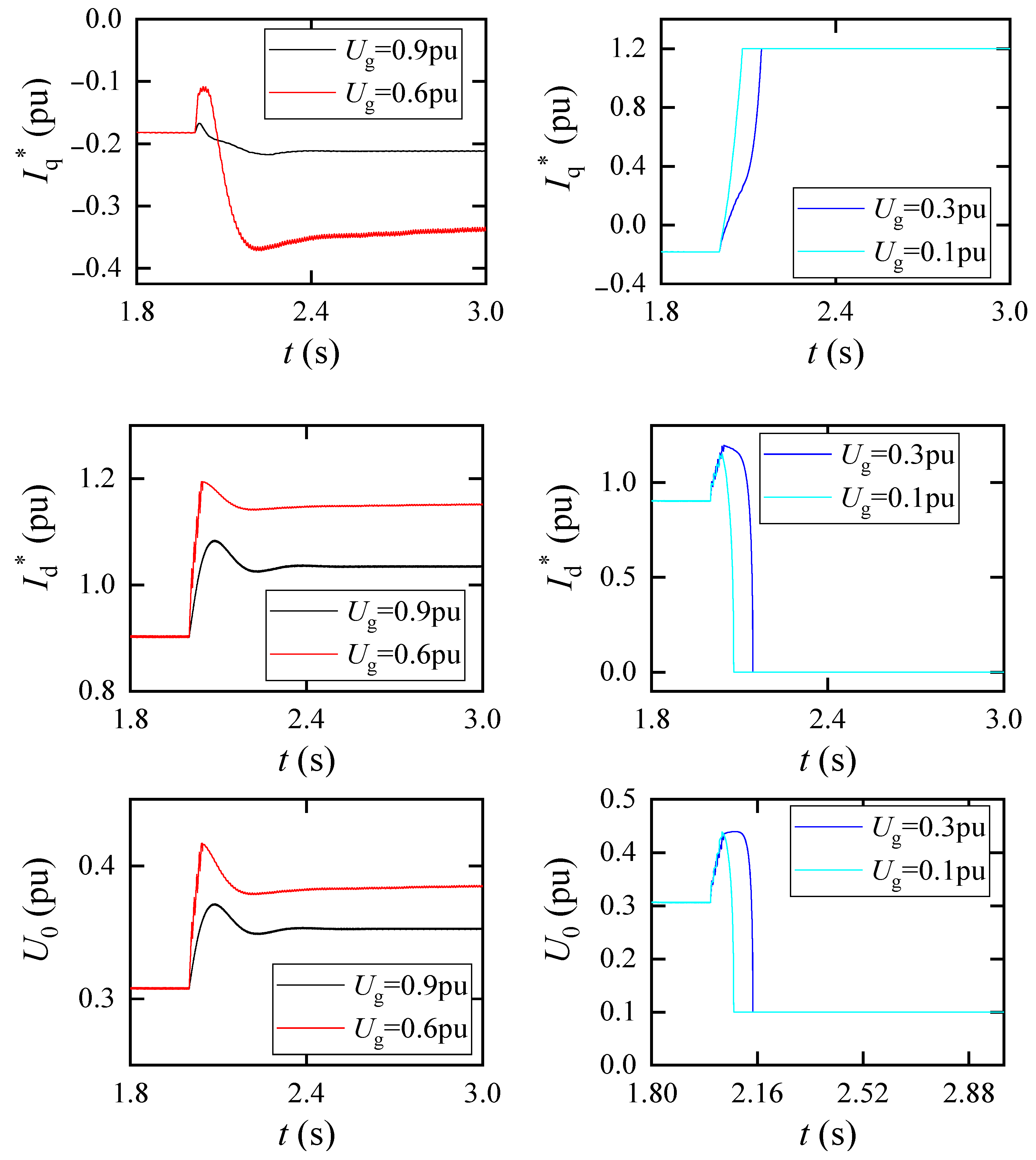
5.4. Impact of Current Saturation Limits

To verify the impact of current saturation limits on transient synchronization stability during severe grid voltage dips, we quantitatively assess system stability by defining the critical grid voltage dip magnitude. This critical magnitude represents the maximum permissible grid voltage dip that the system can tolerate, with a larger value indicating greater stability. Simulations are conducted to determine the grid voltage dip magnitude under varying current saturation limits of the VSC. The results are shown in Table 3.
Table 3 reveals that the critical grid voltage dip magnitude of the VSC decreases as the current saturation limits increase. This observation underscores the fact that under severe grid voltage dips, the VSC’s outer-loop control prioritizes current-limiting control, effectively confining the system’s operation within the constraints imposed by the current-limiting control. Consequently, the VSC’s synchronization equation undergoes a simplification to a second-order form. The VSC will decrease stability as U 0 increases with a higher current saturation limit.

6. Conclusions

Considering the PLL and outer-loop control of VSC, including PI control and current-limiting control, a transient synchronization stability analysis model of VSC is established. The changes in the PLL synchronization equation and the possible existence regions of the VSC’s SEP under different levels of grid voltage dips are delineated, and the transient synchronization characteristics of VSC, considering outer-loop control, are analyzed. The main conclusions of this paper are as follows:
(1) For VSCs employing constant reactive power control, severe grid voltage dips cause the PCC voltage to shift to the negative half of the d-axis, altering the PLL synchronization equation. The existence region of SEP is changed from δ π 2 , π 2 to δ π , π 2 π 2 , π .
(2) Adopting the q-axis prior current limiting strategy results in three configurations of outer-loop control: DC voltage control with reactive power control, d-axis current-limiting control with reactive power control, and d-axis current-limiting control with q-axis current-limiting control. These configurations lead to varied transient synchronization performances of the VSC.
(3) The outer-loop control affects the transient synchronization stability of VSC by modulating reference currents during transient processes. This influence manifests as reactive constraint, active constraint, and current-limiting constraint, with different combinations observed at different depths of grid voltage dips.
(4) In the case of severe grid voltage dips, the VSC outer-loop control switches to current-limiting control completely. Appropriately reducing the current saturation limit can enhance the transient synchronization stability of the VSC.

Author Contributions

Conceptualization, L.C. and L.Z.; methodology, L.C.; validation, L.C., L.Z. and Y.H.; formal analysis, L.C. and Y.L.; investigation, L.C. and Y.L.; resources, L.Z.; data curation, L.Z.; writing—original draft preparation, L.C., L.Z. and N.Y.; writing—review and editing, L.C., L.Z. and N.Y.; visualization, L.Z.; supervision, L.Z.; project administration, L.G; funding acquisition, L.G. All authors have read and agreed to the published version of the manuscript.

Funding

This research was funded by National Nature Science Foundation of China, grant number 52077080.

Data Availability Statement

All data generated or analyzed during this study are included in this published article.

Conflicts of Interest

The authors declare no conflicts of interest. The funders had no role in the design of the study; in the collection, analyses, or interpretation of data; in the writing of the manuscript; or in the decision to publish the results.

References

  1. Li, X.; Liu, S.; Tian, Z.; Huang, M.; Sun, P.; Zha, X.; Hu, P. A Conservatism Improved Transient Stability Analysis of Grid-Following Converters Based on the Proposed Elliptic-Equal Area Criterion. IEEE Trans. Power Deliv. 2024, 39, 1110–1123. [Google Scholar] [CrossRef]
  2. Zhang, Y.; Zhang, C.; Yang, R.; Molinas, M.; Cai, X. Current-Constrained Power-Angle Characterization Method for Transient Stability Analysis of Grid-Forming Voltage Source Converters. IEEE Trans. Energy Convers. 2023, 38, 1338–1349. [Google Scholar] [CrossRef]
  3. Zhao, C.; Sun, D.; Duan, X.; Nian, H. Current Reference Optimization for Inverter-Based Resources to Mitigate Grid Voltage Unbalance Factor. IEEE Trans. Power Syst. 2024, 39, 6103–6106. [Google Scholar] [CrossRef]
  4. Patel, M. Opportunities for Standardizing Response, Modeling and Analysis of Inverter-Based Resources for Short Circuit Studies. IEEE Trans. Power Deliv. 2021, 36, 2408–2415. [Google Scholar] [CrossRef]
  5. Xing, G.; Chen, L.; Min, Y.; Tang, Y.; Li, Y.; Xu, S. Effects of PLL Frequency Limiters on Synchronization Stability of Grid Connected VSC and Strategy to Realize Global Stability. IEEE Trans. Energy Convers. 2023, 38, 2096–2107. [Google Scholar] [CrossRef]
  6. Fan, L.; Miao, Z. Root cause analysis of AC overcurrent in July 2020 San Fernando disturbance. IEEE Trans. Power Syst. 2021, 36, 4892–4895. [Google Scholar] [CrossRef]
  7. Taul, M.G.; Wang, X.; Davari, P.; Blaabjerg, F. An Overview of Assessment Methods for Synchronization Stability of Grid-Connected Converters Under Severe Symmetrical Grid Faults. IEEE Trans. Power Electron. 2019, 34, 9655–9670. [Google Scholar] [CrossRef]
  8. Wu, H.; Wang, X. Design-Oriented Transient Stability Analysis of PLL-Synchronized Voltage-Source Converters. IEEE Trans. Power Electron. 2020, 35, 3573–3589. [Google Scholar] [CrossRef]
  9. Wang, Z.; Guo, L.; Li, X.; Pang, X.; Li, X.; Zhou, X.; Wang, C. PLL Synchronization Transient Stability Analysis of a Weak-Grid Connected VSC During Asymmetric Faults. IEEE Trans. Power Electron. 2024, 39, 2140–2154. [Google Scholar] [CrossRef]
  10. He, X.; Geng, H. PLL Synchronization Stability of Grid-Connected Multiconverter Systems. IEEE Trans. Ind. Appl. 2022, 58, 830–842. [Google Scholar] [CrossRef]
  11. Pei, J.; Yao, J.; Liu, Y.; Chen, S.; Sun, P.; Huang, S. Modelling and Transient Synchronization Stability Analysis for PLL-Based Renewable Energy Generator Considering Sequential Switching Schemes. IEEE Trans. Power Electron. 2021, 37, 2165–2179. [Google Scholar] [CrossRef]
  12. Tang, Y.; Tian, Z.; Zha, X.; Li, X.; Huang, M.; Sun, J. An Improved Equal Area Criterion for Transient Stability Analysis of Converter-Based Microgrid Considering Nonlinear Damping Effect. IEEE Trans. Power Electron. 2022, 37, 11272–11284. [Google Scholar] [CrossRef]
  13. Luo, Y.; Yao, J.; Chen, Z.; Huang, S.; Chen, S.; Zhang, Q.; Qin, Z. Transient synchronous stability analysis and enhancement control strategy of a PLL-based VSC system during asymmetric grid faults. Prot. Control Mod. Power Syst. 2023, 8, 35. [Google Scholar] [CrossRef]
  14. Zhang, Y.; Zhang, C.; Cai, X. Large-Signal Grid-Synchronization Stability Analysis of PLL-Based VSCs Using Lyapunov’s Direct Method. IEEE Trans. Power Syst. 2022, 37, 788–791. [Google Scholar] [CrossRef]
  15. Li, X.; Wang, Z.; Liu, Y.; Wang, Z.; Zhu, L.; Guo, L.; Zhang, C.; Zhu, J.; Wang, C. The Largest Estimated Domain of Attraction and Its Applications for Transient Stability Analysis of PLL Synchronization in Weak-Grid-Connected VSCs. IEEE Trans. Power Syst. 2023, 38, 4107–4121. [Google Scholar] [CrossRef]
  16. Hu, B.; Zhao, C.; Sahoo, S.; Wu, C.; Chen, L.; Nian, H.; Blaabjerg, F. Synchronization Stability Enhancement of Grid-Following Converter Under Inductive Power Grid. IEEE Trans. Energy Convers. 2023, 38, 1485–1488. [Google Scholar] [CrossRef]
  17. Pan, D.; Wang, X.; Liu, F.; Shi, R. Transient Stability of Voltage-Source Converters With Grid-Forming Control: A Design-Oriented Study. IEEE J. Emerg. Sel. Top. Power Electron. 2020, 8, 1019–1033. [Google Scholar] [CrossRef]
  18. Li, Y.; Wang, X.; Guo, J.; Wu, H.; Zhao, B.; Wang, S.; Wu, G.; Wang, T. PLL Synchronization Stability Analysis of MMC-Connected Wind Farms Under High-Impedance AC Faults. IEEE Trans. Power Syst. 2021, 36, 2251–2261. [Google Scholar] [CrossRef]
  19. Chen, J.; Si, W.; Liu, M.; Milano, F. On the Impact of the Grid on the Synchronization Stability of Grid-Following Converters. IEEE Trans. Power Syst. 2023, 38, 4970–4973. [Google Scholar] [CrossRef]
  20. He, X.; Geng, H.; Xi, J.; Guerrero, J.M. Resynchronization Analysis and Improvement of Grid-Connected VSCs During Grid Faults. IEEE J. Emerg. Sel. Top. Power Electron. 2021, 9, 438–450. [Google Scholar] [CrossRef]
  21. Zhang, C.; Molinas, M.; Li, Z.; Cai, X. Synchronizing Stability Analysis and Region of Attraction Estimation of Grid-Feeding VSCs Using Sum-of-Squares Programming. Front. Energy Res. 2020, 8, 56. [Google Scholar] [CrossRef]
  22. Wang, T.; Ji, T.; Jiao, D.; Li, Y.; Wang, Z. Transient synchronization stability analysis of PLL-based VSC using Lyapunov’s direct method. Int. J. Electr. Power Energy Syst. 2022, 141, 108135. [Google Scholar] [CrossRef]
  23. Guo, X.; Lin, X.; Huang, G.; Quan, X.; Chen, S. Transient Stability Analysis and Controller Optimization of Grid-Connected Converter Under Input Power Variation. In Proceedings of the 2021 International Conference on Power System Technology (POWERCON), Haikou, China, 8–9 December 2021; pp. 1606–1611. [Google Scholar]
  24. Taul, M.G.; Wu, C.; Chou, S.-F.; Blaabjerg, F. Optimal Controller Design for Transient Stability Enhancement of Grid-Following Converters Under Weak-Grid Conditions. IEEE Trans. Power Electron. 2021, 36, 10251–10264. [Google Scholar] [CrossRef]
  25. He, X.; Geng, H. Transient Stability of Power Systems Integrated with Inverter-Based Generation. IEEE Trans. Power Syst. 2021, 36, 553–556. [Google Scholar] [CrossRef]
  26. Li, X.; Tian, Z.; Zha, X.; Sun, P.; Hu, Y.; Huang, M.; Sun, J. Nonlinear Modeling and Stability Analysis of Grid-Tied Paralleled-Converters Systems Based on the Proposed Dual-Iterative Equal Area Criterion. IEEE Trans. Power Electron. 2023, 38, 7746–7759. [Google Scholar] [CrossRef]
  27. Si, W.; Chen, J.; Zhang, C.; Liu, M. Influence mechanism of DC-bus voltage on synchronization stability of grid-following converter. J. Shanghai Jiao Tong Univ. 2024, 1–19. [Google Scholar] [CrossRef]
  28. Rokrok, E.; Qoria, T.; Bruyere, A.; Francois, B.; Guillaud, X. Transient Stability Assessment and Enhancement of Grid-Forming Converters Embedding Current Reference Saturation as Current Limiting Strategy. IEEE Trans. Power Syst. 2022, 37, 1519–1531. [Google Scholar] [CrossRef]
  29. Gonzalez-Torres, J.C.; Damm, G.; Costan, V.; Benchaib, A.; Lamnabhi-Lagarrigue, F. A Novel Distributed Supplementary Control of Multi-Terminal VSC-HVDC Grids for Rotor Angle Stability Enhancement of AC/DC Systems. IEEE Trans. Power Syst. 2021, 36, 623–634. [Google Scholar] [CrossRef]
  30. Zheng, T.; Lv, W.; Wu, Q.; Li, R.; Liu, X.; Zhang, C.; Xu, L. An Integrated Control and Protection Scheme Based on FBSM-MMC Active Current Limiting Strategy for DC Distribution Network. IEEE J. Emerg. Sel. Top. Power Electron. 2021, 9, 2632–2642. [Google Scholar] [CrossRef]
Figure 1. Circuit and control diagram of VSC.
Electronics 13 03337 g001
Figure 2. Outer-loop current-limiting control diagram of the q-axis prior current limiting strategy.
Electronics 13 03337 g002
Figure 3. Change in SEPs of the second-order model before and after disturbance.
Electronics 13 03337 g003
Figure 4. Schematic diagram of phase change.
Electronics 13 03337 g004
Figure 5. Changes in SEP before and after disturbance. (a) Slight and moderate dips in grid voltage; (b) severe dip in grid voltage with equilibrium point; (c) no equilibrium point.
Electronics 13 03337 g005
Figure 6. Phasor diagram of VSC when the grid voltage drops slightly.
Electronics 13 03337 g006
Figure 7. Phasor diagram of VSC with a medium voltage drop.
Electronics 13 03337 g007
Figure 8. Phasor diagram of VSC with a severe voltage drop. (a) Existence of equilibrium point; (b) absence of equilibrium point.
Electronics 13 03337 g008
Figure 9. Time-domain simulation verification with or without considering outer-loop control. (a) Virtual power angle; (b) d-axis reference current; (c) q-axis reference current.
Electronics 13 03337 g009
Figure 10. Simulation verification of SEP changes. (a) Scenario 1 and Scenario 2; (b) Scenario 3 and Scenario 4.
Electronics 13 03337 g010aElectronics 13 03337 g010b
Figure 11. Simulation verification of system dynamics considering outer-loop control. (a) Reference current; (b) output active power; (c) output reactive power.
Electronics 13 03337 g011
Table 1. VSC transient synchronization characteristic.
Outer-Loop ControlChanges in the PLL EquationChanges in SEPTransient Synchronization Stability
Constant DC voltage control and constant reactive power controlUnchangedUnchangedThe system achieves synchronization under active power constraint and reactive power constraint.
Current-limiting control and constant reactive power controlUnchangedUnchangedThe system achieves synchronization under reactive power constraint and current limiting constraint.
Current-limiting controlChangedChangedIf U g > U 0 , the system operates under current limit constraints, there is a risk of instability, and the stability decreases with the increase in I lim .
If   U g U 0 , the absence of SEP, synchronous instability.
Table 2. System and control parameters.
ParameterValue (in pu If Not Specified)
Rated active power Pn2 MW
Reference AC voltage Un230 kV
Reference frequency fn50 Hz
Rated DC voltage Vdc1.45 kV
DC capacity Cdc0.015 F
Filter inductance Lf0.44
Grid inductance Lg0.36
Grid resistance Rg0.08
DC voltage control coefficientKpdc = 1, Kidc = 50
Reactive power control coefficientKpQ = 1, KiQ = 50
Current control coefficientKpi = 1, Kii = 20
PLL control coefficientKppll = 50, Kipll = 100
Table 3. Critical grid voltage drop amplitude of the system for different current saturation limits.
Current Saturation Limit/puCritical Grid Voltage Drop Amplitude/pu
1.00.86
1.20.85
1.40.83
1.60.80
Disclaimer/Publisher’s Note: The statements, opinions and data contained in all publications are solely those of the individual author(s) and contributor(s) and not of MDPI and/or the editor(s). MDPI and/or the editor(s) disclaim responsibility for any injury to people or property resulting from any ideas, methods, instructions or products referred to in the content.

