Abstract
The number of HVDC installations is increasing and the decarbonization of power systems makes it necessary to install storage systems. It might become relevant to assess the synergies between both trends by connecting storage systems on the DC side of HVDC systems. The contribution of this paper is to show the feasibility and the design of such a system to provide three different ancillary services: power oscillation damping (POD), fast frequency response (FFR), or wind power oscillation smoothing. The DC storage system consists of a series connection of sub-modules with energy storage devices connected to each sub-module through a DC-DC converter. For the proposed design methodology, a first simple average model of the DC storage converter is developed to run preliminary EMT simulations to obtain power profiles for the energy storage elements according to the system needs. These profiles are used as inputs for designing the storage system. The design methodology is validated by performing new EMT simulations with a more detailed model which includes a model of the storage elements. Results show that the designed system can provide the expected services and sizing results confirm the technical feasibility of the solution.
1. Introduction
The current trends in power systems push for the installation of new high-voltage direct current (HVDC) systems to connect asynchronous areas, to reinforce AC systems with cable transmission or connect remote offshore wind farms. This increased penetration of HVDC systems in power systems leads to a growing interest regarding the services these systems could offer, additionally to transferring bulk power. This includes, for instance, black-start [1], inertia support [2] and grid-forming capabilities [3,4,5].
At the same time, the increased penetration of less controllable energy sources and power electronic interfaced devices (leading to system inertia reduction) raises the need for energy storage to keep the system stable and to ensure secure supply of electrical energy to customers [6]. Flexibility will be crucial, and energy storage is seen as a key enabler for a power system dominated by power electronics and non-dispatchable resources.
Although pumped hydro storage still counts for more than 90% of storage installed capacity, electrical/electrochemical storages are the most rapidly growing forms of technology in the power system, while hydrogen is emerging. Furthermore, with the constant increase in energy needs worldwide, there is no shortage of perennial economic drivers for energy storages [7]. Along with this growing penetration, the power system, and more generally grid-connected power converters, are experiencing a major step up with the remarkable advancement in power electronics. Therefore, recent works of the past few years have looked to new approaches to interface storage to the grid. This aims at increasing the attractiveness of energy storage assets while benefiting from the advantages of new popular power converter topologies [7].
Energy storage connected to AC systems is currently used in power systems. The most common solution consists of multiple transformers connected to low-voltage converters connected to a fraction of the energy storage elements. This distributed solution is commonly based on standardized containers that can be easily delivered and commissioned. However, with the rise of power electronics, alternative solutions have started to be pushed on the market to harness the benefits of innovative converter topologies. Nowadays, manufacturers propose new STATCOM products, initially used for reactive power compensation, with enhanced energy storage capability [8,9,10,11]. They are based on multilevel converters (MMCs), similar technologies to those used in modern HVDC installations.
Research works are investigating the possibility to embed energy storage elements in HVDC applications, either in MMCs [12,13,14] or connected to the DC side [15].
The first option aims at embedding the energy storage within some or all of the thousands of submodules of the converter. Note that an interface converter should be implemented to connect the energy storage devices to the submodule capacitor in order to decouple the voltage variation of both elements [16].
The second option leads us to consider multi-terminal DC systems with a new kind of DC terminal, different from AC/DC converters: DC-connected energy storage converters. Few papers have investigated such devices. In fact, the design of such a solution is not straightforward as energy storage elements are based on the series/parallel connection of low-voltage elements, with limited voltage range due to safety issues, while HVDC systems reach hundreds of thousands of volts. Reference [17] considers centralized energy storage (energy storage elements in series to reach up to hundreds of kilovolts) interfaced to HVDC terminals through a DC-MMC as a DC/DC converter interface. Some other works consider a DC/AC/DC conversion stage to interface the energy storage elements and the HVDC terminals [18]. The other papers consider distributed energy storage where the converter is made of series-connected submodules to which a fraction of the energy storage elements are connected [19,20,21,22]. Those topologies suggest that the use of small storage devices is more attractive to reduce the individual requirements of components and ease the integration of storage devices. Note that, when two branches are implemented, an internal ac current can be injected to help the energy balance between the submodules of both legs [23], while for a single branch, this is not possible, but fewer components are needed [22].
Nonetheless, there are barriers to fostering the adoption of such systems: on the one hand, deriving the specifications of the energy storage converter and, on the other hand, choosing the storage technology, sizing its main components, and assessing its feasibility. This paper aims at overcoming these barriers (as in [23] for energy storage in MMCs and a specific service). This paper considers an offshore wind farm connected to the shore through an HVDC link including energy storage on its DC bus interfaced by a DC-DC converter. An approach is proposed to size the main components of an HVDC-connected energy storage converter to provide services to the AC system. The methodology is applied to three potential services and the sizing results are used to comment on the technical feasibility.
The main contributions of this paper are as follows.
- A comprehensive approach is proposed to size an energy storage device and the corresponding converter connected to HVDC terminals for a specific service.
- This approach is used for three examples of AC services to obtain the characteristics of the main components of the converter, including the energy storage elements.
- The feasibility of the obtained energy storage converters is discussed for the three considered examples.
The rest of this paper is organized as follows. The next section first introduces the considered energy storage converter: its structure, model and control. Secondly, it presents the proposed methodology to obtain requirements for a specific use case and to derive a proper sizing of the main components of the converter and its energy storage. Section 3 presents the considered services and the corresponding models of AC systems used to perform the simulation studies. This section also includes the requirements obtained from the first simulations. These values are used in Section 4 to size the energy storage converter. Then, detailed simulations are shown to verify the ability of the designed energy storage system to provide the expected services. Finally, Section 5 gives conclusions on the proposed approach and the feasibility of the obtained energy storage converters.
2. Proposed Converter to Integrate Energy Storage in an HVDC System and Methodology to Assess Its Technical Feasibility
2.1. Topology
The converter topology considered in this work is a branch of series-connected energy storage submodules, which was introduced in [22] and is depicted in Figure 1. The branch of energy storage submodules (ES-SMs) is connected to the HVDC side via an inductor (). The ES-SMs are made of a half-bridge (HB) connected to a capacitor (). Each capacitor is also connected to a storage device by means of a dc-dc converter (composed of another HB and an inductor). The storage device is a supercapacitor in this work, though a battery can also be considered. Even if connecting an energy storage element directly to the SM capacitor could appear at first glance to be the easier method, it has already been shown that an active interface is compulsory for attractive energy management purposes [16]. Note that the proposed topology is easily scalable in terms of power/voltage due to a structure based on elementary building blocks. This also enables the use of standard semiconductors. In addition, simpler maintenance can be achieved by changing only the damaged energy storage submodule (or the associated energy storage elements). Finally, supercapacitors can be fully discharged, limiting the risk during maintenance or the need for trained staff to work on energized equipment. Moreover, supercapacitors can operate within a large range of room temperatures, can be used for many cycles, offer long life durations, have good properties regarding recyclability, and are not prone to catching fire, even in cases of short circuits [6].
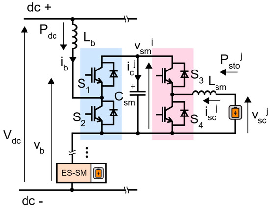
Figure 1.
Detailed view of the single branch of energy storage submodules.
The single branch of ES-SMs can inject or absorb power from the HVDC system, which determines the sign of and . Using a single branch does not allow AC circulating currents to balance between branches like in [21]. In both half-bridges ({, } and {, }), switches are operated in a complementary way, providing two degrees of freedom to each ES-SM.
On the one hand, the ES-SM can be inserted or bypassed using the switches and . For a positive , the capacitor can be charged ( closed) or bypassed ( closed). When is negative, it is discharged ( closed) or bypassed ( closed).
On the other hand, by using the switches and , power between the capacitor and the storage element can be exchanged. When > 0, which implies < 0, is discharged ( closed) or disconnected ( closed) from the storage device. When < 0, > 0, is charged ( closed) or disconnected ( closed) from the storage device.
2.2. Modelling
Two types of average models of the single branch of energy storage are developed, which are used for different purposes (see Section 2.4): Model A and Model B.
2.2.1. Model A
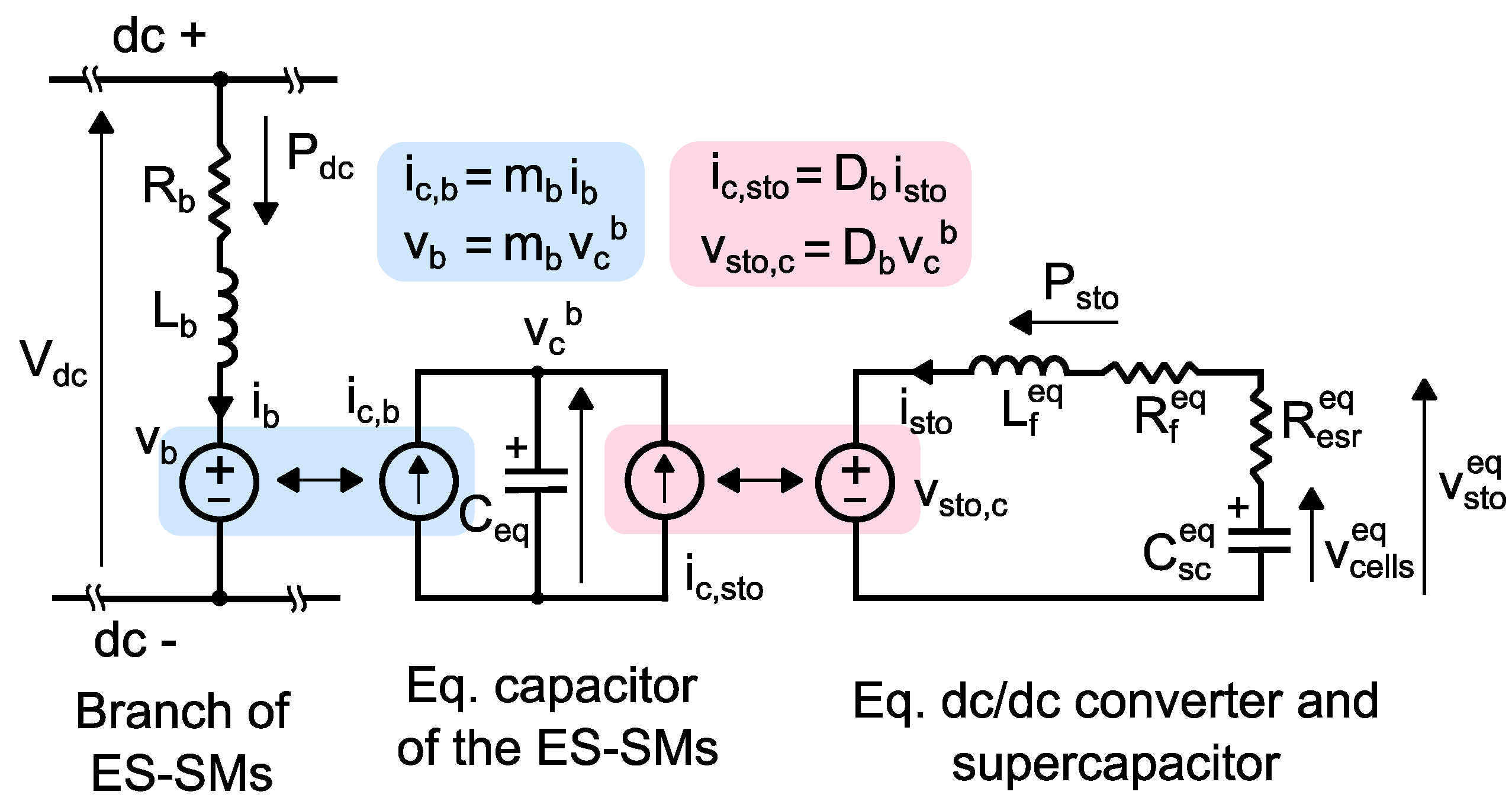
This model considers that all the ES-SMs are identical and that their capacitor voltage and storage voltage are totally balanced. Thus, all the ES-SM capacitors and supercapacitors are modelled as a single equivalent capacitor and a single storage supercapacitor. The average model is presented in Figure 2. It is composed of three separated circuits linked by means of coupled voltage and current sources.
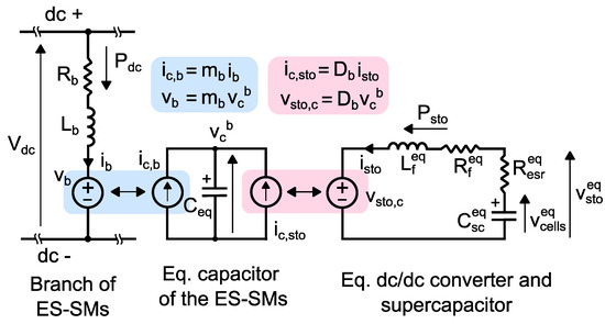
Figure 2.
Model A of the single branch of energy storage submodules.
The insertion and bypass orders (corresponding to , ) can be averaged to a modulation index () [24], and the inserted voltage of the stack of ES-SMs is represented by an equivalent voltage source () as shown in the left part of Figure 2. This voltage source is coupled to a current source () in a separated circuit (centre of Figure 2) that is connected to the equivalent capacitor .
Another current source () is also connected to the capacitor , modelling the current coming from the storage devices. This current source is coupled to a voltage source (), which represents the equivalent voltage source inserted by the dc-dc converters in the supercapacitor equivalent circuit (right part of Figure 2). The behaviour of the dc-dc converters (corresponding to , ) is also averaged to an equivalent duty cycle (). The inductance and resistance in the supercapacitor circuit represent the equivalent inductance () and parasitic resistance () of the dc-dc converters. Finally, the equivalent supercapacitor is modelled as an equivalent resistance in series () and an equivalent capacitance ().
The relations between the passive components of the single branch of energy storage submodules and its average model are presented in Equations (1)–(3), where is the number of ES-SMs in the single branch of storage submodules; is the capacitance of the capacitor in an ES-SM; is the capacitance of one supercapacitor bank in an ES-SM; is the filter inductance in an ES-SM.
More details of the average model can be found in [22].
2.2.2. Model B
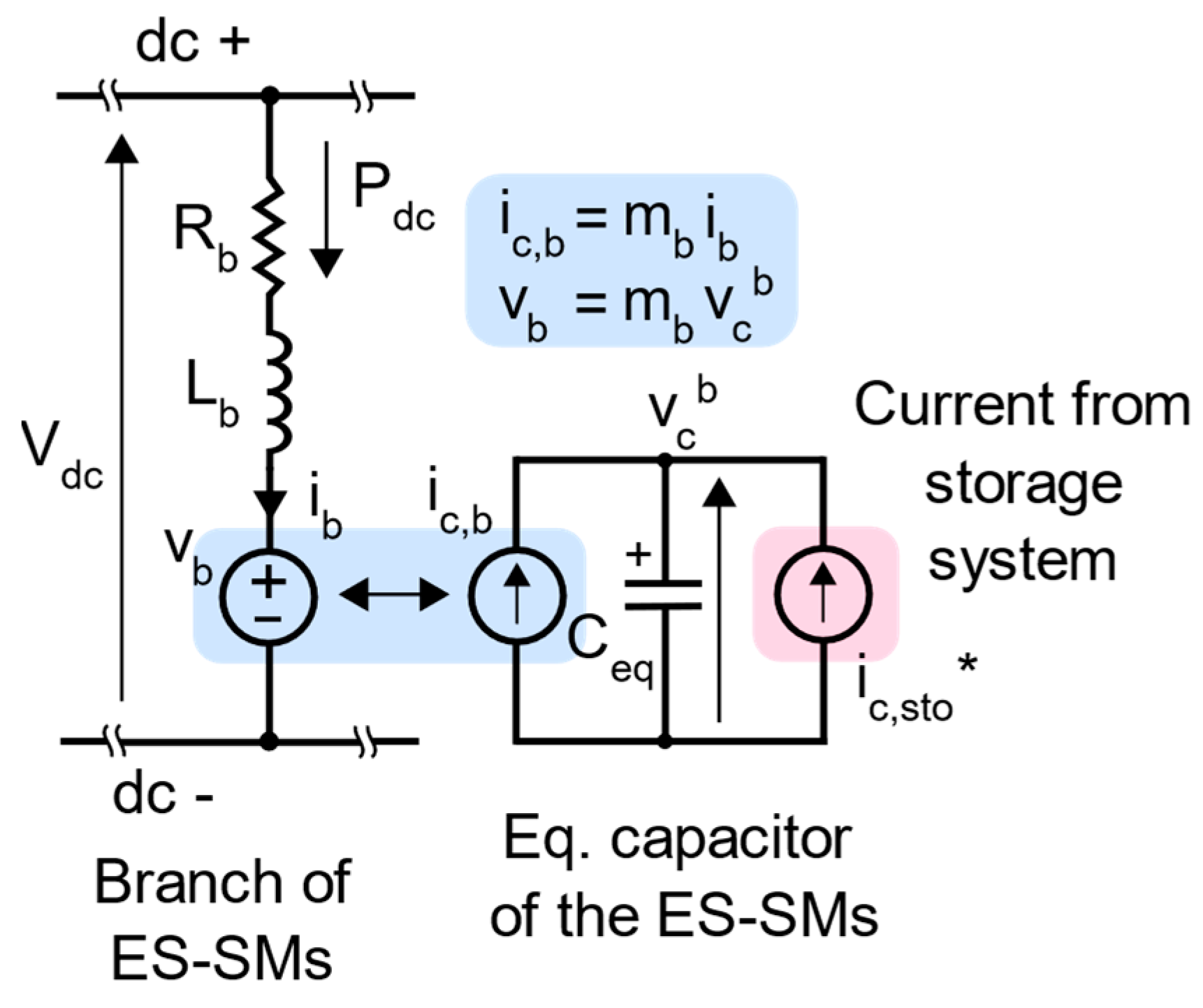
This model follows similar hypotheses to Model A but with a simplification: the equivalent dc-dc converter and supercapacitor are not modelled but replaced by a controlled current source in the equivalent capacitor circuit as shown in Figure 3. It can be noticed that the parameters related to the dc-dc converters and supercapacitors are not required for this model. The aim of this model is to run simulations while the energy storage elements are not sized. Such simulations are useful to derive energy storage requirements by simulating a current source that is controlled to provide the expected service.

Figure 3.
Model B of the single branch of energy storage submodules.
2.3. Control
The control approach of the single branch of energy storage submodules is presented in this section for Model A. At the end of the section, the simplifications of the control schemes to be adapted to Model B are also outlined.
As mentioned before, the single branch of energy storage submodules provides two degrees of freedom. The first one is associated with the switches and and corresponds to the modulation index . The second one is associated with the switches and associated with the duty cycle of the equivalent dc-dc converter . Two control objectives must be fulfilled thanks to these two degrees of freedom: controlling the power absorbed or injected into the HVDC link and regulating the energy in the equivalent capacitor . Two control schemes can then be defined. In the first one, controls the power exchange with the HVDC link while regulates the energy in the submodule capacitors. In the second one, the power exchange is controlled by and the energy in the submodule capacitors is controlled by . The authors determined through simulations that both approaches are suitable for average models (as in this paper). However, it should be noted that balancing techniques should be implanted when considering the behaviour of each submodule instead of average models. Ongoing work on detailed models reveals that the first strategy (the duty cycle of each DC/DC converter is used to control the submodule capacitor voltage) shows better performance. Balancing techniques are out of the scope of this paper. Moreover, those modifications have limited impact on the dynamics analyzed in this study and do not change the conclusions on the converter feasibility (current and voltage waveforms are similar). Therefore, in the rest of this paper, the first developed control architecture is used.
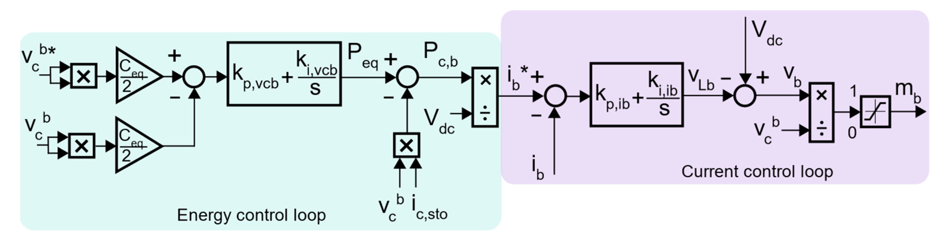
The control scheme to regulate the energy of the equivalent capacitor is illustrated in Figure 4, which is composed of two cascaded controllers. The outer loop compares the measured energy of the capacitor with the reference and outputs the required branch current (). The inner loop controls the branch current to the reference value and outputs the required modulation index for the branch.
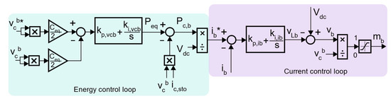
Figure 4.
Energy control scheme of the average model of the single branch of ES-SMs.
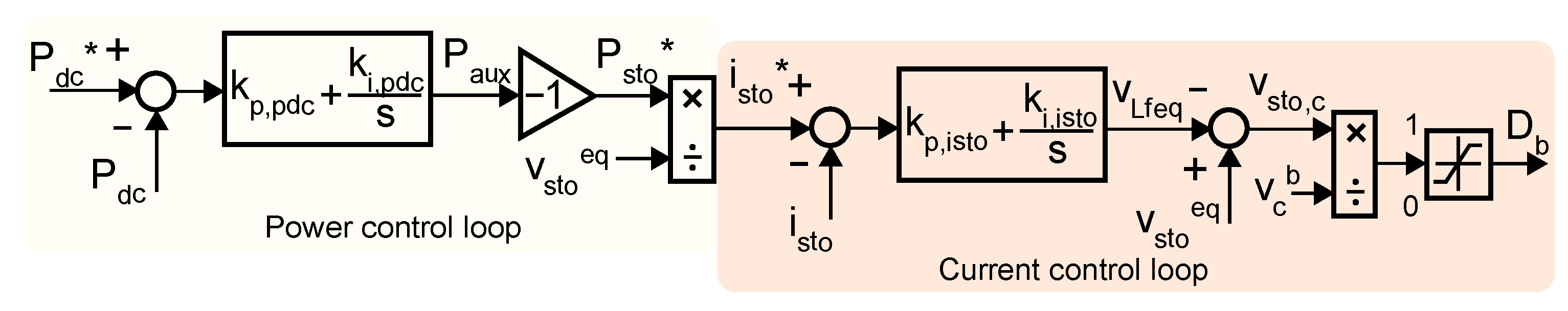
The control scheme to regulate the dc power is depicted in Figure 5, which also contains two cascaded controllers. The outer loop compares the measured dc power with the reference value and outputs the power (current) that the storage has to provide (these two powers are not exactly equal as a consequence of the internal losses in the branch). Then, the storage current reference () is given to the inner current loop that provides the duty cycle of the equivalent dc-dc converter.
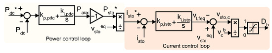
Figure 5.
Power control scheme of the average Model A of the single branch of ES-SMs.
In both control schemes, the inner controller is designed to be faster than the outer controller. The details regarding the tuning of the controllers can be found in [22].
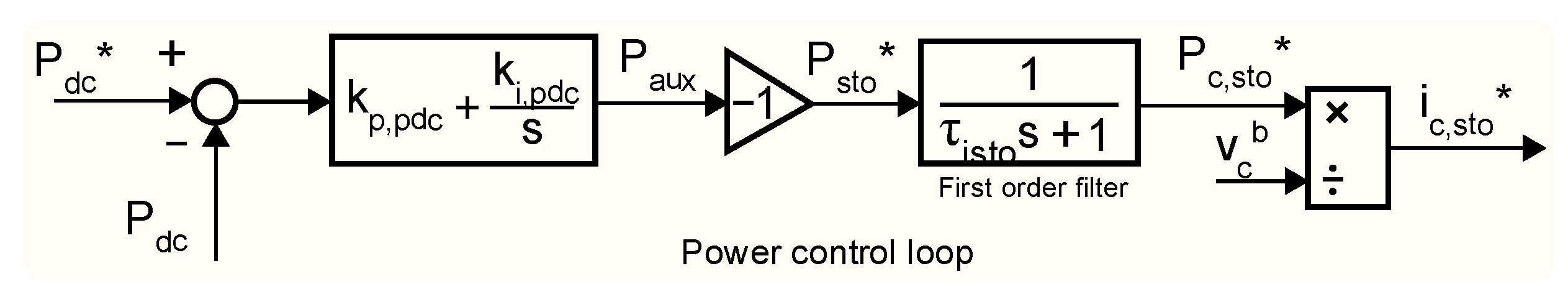
Model B considers the same energy control scheme as that in Figure 4, but the power control scheme is simplified since the dc-dc converters and the supercapacitors are modelled as a controlled current source. Therefore, the simplified power control scheme is illustrated in Figure 6, showing only a power control loop whose is given to a first-order filter that models the dynamics of the dc-dc converter and supercapacitor. The output is given to the controlled current source in Figure 3.
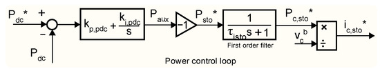
Figure 6.
Power control scheme of the average Model B of the single branch of ES-SMS.
2.4. General Methodology
As the proposed paper sheds light on the feasibility of embedding energy storage within an HVDC system, it is necessary to assess the requirements and the characteristics for the energy storage for different ancillary services. In that context, this study is composed of three parts to obtain system specifications, size the proposed solution, and validate it.
To quantify the amount of energy and the power requested from the energy storage, the following methodology is applied. The proposed single branch of energy storage submodules and its control scheme are first modelled for electromagnetic transient (EMT) simulation purposes (EMTP software in this paper). A simple model (Model B) is considered to run simulations without any known parameter regarding the energy storage elements. This is integrated in different grid simulations, depending on the proposed use case (see Section 3). Then, simulations are performed to estimate the power and energy requirements for different ancillary services. The interest of EMT simulations is to consider both the dynamics of the grid and the power converter control, and thus defining adequately the input parameters for the converter design.
In a second instance, these system results and grid parameters are used as inputs to determine the power converter’s topologies and its energy storage system characteristics. For that purpose, a design methodology, described further in this paper, is implemented to evaluate all the key parameters of both systems as passive elements for the converter or the number of modules of the energy storage system. Note that key performance indicators can be defined to compare the different solutions in a relative approach and to highlight the benefits and disadvantages of each of them.
In a third stage, to validate the design of the proposed solution, a more detailed model (Model A) is considered and the grid simulations for each use case are played again considering this new set of parameters.
2.5. Design of the Solution
This section depicts the sizing of the main elements of the single branch of energy storage submodules and its energy storage system. Section 2.5.1 focuses on the main parameters of the branch (number of submodules, capacitance, branch inductance, etc.), while Section 2.5.2 deals with the parameters of the interface dc-dc converter and the storage elements.
2.5.1. Single-Branch Energy Storage Submodules
This subsection deals with the sizing of the main parameters of the single branch of energy storage submodules, following the same principles as in [22].
- Number of energy storage submodules
The minimum number of energy storage submodules is calculated according to the energy storage submodule capacitor voltage (that is equivalent to the sum of voltages in all the energy storage submodules ). The minimum value of comes from assuming a maximum modulation index in steady-state operation to ensure a margin for proper operation during transients ( is assumed here) and the calculation of the required modulated voltage by all the submodules to transmit the nominal power. The voltage drop due to is also taken into account, leading to Equation (4).
Then, the minimum voltage of the energy storage submodules can be calculated with Equation (5), considering an average voltage for all the energy storage submodules ().
- Branch inductor
The branch inductor is designed to protect the switches against short-circuit currents during a dc fault. It is assumed that the dc bus voltage is applied at the terminals of the inductor, leading to a current increase. The fault is detected once the branch current reaches a given threshold . Here, the threshold is set at 1.5 pu of the maximum peak current within the branch in normal operation. Then, a signal to block the ES-SMs is sent to the branch to protect the IGBTs. A time delay (0.3 ms in this work) is assumed between the sending of the signal and the actual blocking of the IGBTs, which can account for processing and communication delays. The inductance must ensure that the current remains under the maximum rating of the IGBTs and until the blocking happens. Note that the maximum repetitive peak forward current is considered for this value. Consequently, the value of the branch inductance is calculated using Equation (6).
- Energy storage submodule capacitance
The submodule capacitance is determined according to four criteria, which are based on the maximum acceptable overvoltage after blocking (criteria 1 and 2), acceptable undervoltage after a dc fault (criterion 3), and the maximum voltage ripple due to the dc-dc converter (criterion 4). Then, the most restrictive value is selected.
Criterion 1 is based on the maximum overvoltage allowed by the capacitor after the blocking of the ES-SMs when the branch current is positive (). After blocking the ES-SMs, the current circulates through the diode, charging the capacitor, while (in the worst case) the current in the storage circulates through diode . The sum of the voltage of all capacitors is higher than ; thus, the current will eventually go to 0. In the meantime, an amount of energy comes from the HVDC system, and the inductor is transferred to the equivalent of the ES-SM, increasing its voltage . By setting a maximum admissible voltage in the equivalent capacitor and an initial voltage , it is possible to isolate and calculate the required equivalent capacitance from Equation (7), where (equal to ) is the equivalent submodule capacitance and is the branch current at the blocking time. Note that the worst operating point is considered (nominal power).
In this paper, is assumed to be 20% higher than the nominal value.
Criterion 2 is also based on the maximum overvoltage allowed in the capacitor after the blocking but considering the branch current negative (). This time, the current coming from the storage device is the one charging the capacitor (through diode ). If analysing a single ES-SM, the nominal voltage of the storage device is lower than , which means that the storage current will eventually go to 0, but the ES-SM capacitor will be charged during this time interval. By setting a maximum admissible voltage for the capacitor and an initial voltage , Equation (8) can be used to find the required capacitance , where is the storage current at the blocking time.
Criterion 3 focuses on the acceptable undervoltage during a dc fault. Between the time the fault is detected and the blocking of the switches, the fault current discharges the inserted submodule capacitors if the branch current is negative. To avoid uncontrollable conduction of the diode of switch , the voltage of the submodule capacitors must not be lower than the voltage of its energy storage system. Note that, at the same time, the branch current keeps increasing since the sum of the voltage capacitors is applied at the terminal of the inductor. Consequently, the equivalent capacitance (equal to ) must be determined according to Equation (9) to prevent this scenario. In this case, the energy provided by the capacitors (right part of Equation (9) is transferred to the inductor, which increases its current (left part of Equation (9)), where represents the number of inserted energy storage submodules. It is defined by the product of the number of submodules within the branch and the maximum modulation index . is the final voltage value of the sum voltages in the capacitors given by , while corresponds to the initial equivalent capacitor voltage inserted as .
Criterion 4 computes the necessary capacitor filtering in a bidirectional dc-dc converter based on the maximum voltage ripple (). Then, the required submodule capacitor is given by Equation (10), where indicates the fraction of time the submodule capacitor is inserted in the dc-dc loop during a switching period. is the maximum current circulating through the branch. is the switching frequency of the submodules (assuming a PWM strategy).
It is assumed in this paper that the acceptable voltage ripple in the submodule capacitor is set at 5% of its nominal value.
Then, the selected capacitance of the submodule capacitor is given by Equation (11).
- Switch choice
For the switches, in this work, IGBTs with a voltage rating of 6.5 kV are selected as main components. The current rating, though, will depend on the maximum power to be provided by the converter.
2.5.2. Energy Storage Interface Converter
In this subsection, the design of the interface converter between the energy storage submodule capacitor and the energy storage element is addressed. Note that the structure of the interface converter depends on the modular converter into which it is integrated. In the case of MMC with embedded energy storage, a serial connection of dc-dc converters with high switching devices can be interested as the number of submodules is high and the power to be supplied by the energy storage function is generally low in regard to the rating power of the converter [16]. In opposition, an interleaved converter seems more suited for STATCOMs with integrated energy storage, as the number of submodules is low with a high power density [25]. In this paper, a simple bidirectional dc-dc converter with IGBTs as switching devices is considered. The number of submodules and their power density are well suited to consider this common topology.
For a dc-dc converter, the design of the passive components is pivotal. As seen in the previous subsection, the design of the filtering capacitor is considered in the sizing of the submodule capacitor as additional criteria. Thus, only the inductor remains to be sized. A conventional method based on the maximum allowed current ripple ( is used assuming the dc-dc converter is operated at a given switching frequency ; see Equation (12).
Note that the worst case happens when the duty cycle equals 0.5. In this work, the inductance value is defined to ensure a ripple of 10% of the dc current flowing through the supercapacitors when the energy storage voltage is at its lowest value as soon it is greater than half its nominal voltage.
Finally, the question of the switches remains to be addressed. Although IGBT switches with the same voltage blocking capability (that is to say, 6.5 kV) as the main half-bridge of a submodule can be selected, the current rating cannot be the same. A higher current capability would be required as supercapacitors have been selected as energy storage devices. Indeed, their strong voltage variation leads to greater currents at constant power. Therefore, the switch current rating of the interface converter is selected according to the maximum continuous current allowed by the series–parallel connection of supercapacitor modules (cf. Section 2.6) during the sizing process.
2.6. Design of the Energy Storage of an Energy Storage Submodule
In this paper, the studied services (cf. Section 3) require lower overall energy storage capabilities than the traditional bulk energy storage services as primary reserves. Therefore, this study is limited to mature energy storage technologies with high power capability. Supercapacitors are selected as they are well suited for the proposed grid services with low time constants and high-power requirements. High cyclability and lifetime are other benefits of this technology. Furthermore, a supercapacitor does not represent a thermal threat, despite the millions of cycles at high current that can achieved. It is a key feature in terms of safety in the framework of HVDC applications. In the same way, the energy stored in a supercapacitor bank can be totally dissipated, meaning that zero voltage at the terminals of the cells can be reached. Once grounded and short-circuited, the risk is lower for the operators with less restrictions for maintenance and staff requirements. For the rest of the study, SkelMod 102V-88F, a supercapacitor energy storage module for grid applications, from Skeleton, is selected as an elementary building block [26].
The goal of the sizing methodology is to define the required number of supercapacitor modules per energy storage submodule. As the total number of modules reflects the volume and the cost of the energy storage, minimizing its number is a priority. Note that the following assumptions are considered:
- The influence of the thermal behaviour of the solution and switching harmonics on lifetime and system performance are neglected.
- Ageing is not considered, meaning that the design of the storage is made for the beginning of life (BoL).
- Load profile can be achieved upwards or downwards. This means that more energy is stored within the energy storage system to ensure both power directions.
- The maximum continuous current for a given temperature rise provided by the manufacturer datasheet is considered as the current limit (285 A for a rise of 40 °C for non-repetitive services with a short duration, 172 A for a rise of 15 °C for services that should be provided for a long duration [26]).
- Sizing at constant power is achieved. This means that the sizing cycles of the load profiles are simplified as an equivalent constant power load.
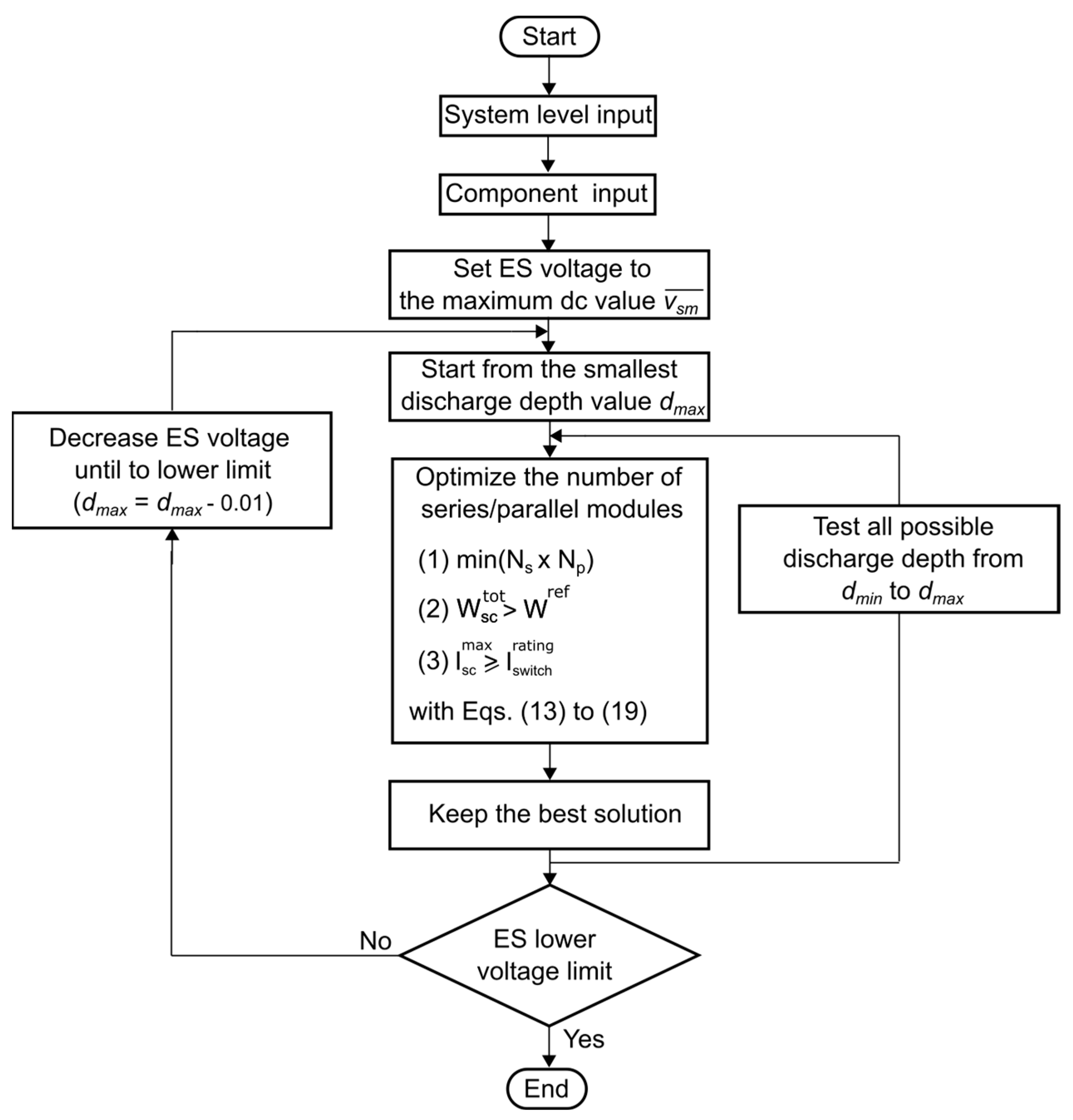
Whatever the application, the design of a supercapacitor bank must satisfy two conditions: to store enough energy for the expected ancillary services and to be able to provide the requested power. Figure 7 presents the workflow of the simplified algorithm used to define the minimum number of modules for a supercapacitor bank.

Figure 7.
Methodology to define the minimum number of modules for a supercapacitor bank.
Knowing system-level and component parameters, the energy storage voltage is first set at its maximum voltage. In this paper, a value of 3 kV is selected. This means a buck behaviour from the dc-dc converter interface (a value of 3.8 kV is chosen for the submodule capacitor voltage).
Similarly, to consider the voltage variation of a supercapacitor bank, a dynamic lower voltage limit is also set. This value is computed to avoid an important voltage ratio (i.e., between the dc bus and the energy storage voltage) for the dc/dc converter, but it also ensures that the current that will flow through the energy storage system will respect the maximum continuous and peak current provided by the datasheet.
Once these values are defined, the main part of the algorithm computes the minimum number of supercapacitor modules for each possible depth of discharge from nominal to minimum voltage. This is carried out respecting the minimum energy to store and the electrical constraints of the system (that is to say, current and voltage limits).
The method is based on [27]. The main points are outlined below. Thus, the maximum voltage at the terminals of the supercapacitor bank of an energy storage submodule imposes the number of modules in series as in Equation (13) with the nominal voltage of a supercapacitor module.
In the same way, the number of branches in parallel depends on the maximum power requested by a submodule () at minimum voltage , see Equation (14). This means that the current flowing through the branch of the supercapacitor bank should not exceed the maximum current allowed by a module.
Furthermore, the total energy stored within a supercapacitor bank depends on the series–parallel connection of the number of modules as in Equation (15) with , the depth of discharge, that corresponds to the ratio between the minimum allowed voltage and the nominal voltage that defines a supercapacitor bank defined in Equation (16), and , the equivalent capacitance of the bank, knowing the capacitance of a module , see Equation (17).
Finally, note that when a supercapacitor bank operates at constant power, the equivalent internal voltage of the device is limited by the kinetics at which energy can be extracted, see Equation (18). Therefore, it imposes a maximum discharge ratio due to the equivalent series of the supercapacitor bank defined in Equation (19).
As this method is an iterative process, it is repeated by decreasing step-by step the initial maximum allowed voltage in series (~equivalent to the number of modules in series), until it equals the minimum voltage limit. At the end, the best configuration that minimizes the total number of modules is kept.
Furthermore, it has to be noted that the maximum module current, at the minimum energy storage voltage, should remain below the maximum current rating of the selected switches.
2.7. Key Indicators
Based on the design of the single branch of energy storage submodules and its independent energy storage, performance indicators can be defined to make a comparison among the different case studies. Regarding the energy storage of a submodule, the total number of supercapacitor modules is the main indicator as defined in Equation (21).
It allows us to assess the volume and weight of the solution from submodule and system standpoints. Thus, a first insight on the feasibility of an energy storage submodule can be discussed. Similarly, it provides an indication of the potential cost, as one of the main parts of the latter is due to the total energy stored.
From the same perspective, a utilization factor is defined to optimize the energy used. It stands for the ratio between the useful energy for the ancillary services and the total energy stored in the system as defined in (22). It highlights whether the proposed solution is oversized regarding the ancillary services to provide.
Finally, the required switches and passive components for the submodules of the single-branch converter and the interface converters will provide indications of the required power converter system as the quantity of silicon to build the converter.
3. Case Studies
This section presents the proposed case studies for investigating the considered converter. They will be first simulated in the EMT domain, using Model B, before proceeding to the sizing process. Three case studies are included in this paper. Each time, an offshore wind farm is connected to an ac power system. According to the case study, the characteristics of the ac grid are modified to shed light on a specific disturbance. In the first example, the HVDC-connected wind farm is connected to an ac grid that is prone to inter-area oscillations. Thus, a Kundur-based model is used to emulate the ac power system. In the second case study, the HVDC link is used to provide fast frequency response to a weak ac grid, while the last case study illustrates eigenmode during offshore wind farm (OWF) power production. Note that each case study is built to address a given ancillary service from fast response to oscillation damping to wind generator power smoothing. In the following subsections, each case study is briefly depicted and the corresponding requirements for the energy storage system are highlighted.
3.1. Inter-Area Power Oscillation Damping
Figure 8 presents the system used to design an energy storage system for inter-area power oscillation damping. The ac power system is composed of two areas interconnected by two 400 kV ac transmission lines. Each area includes a 900 and 9000 MVA generator equipped with a power system stabilizer (PSS) and automatic voltage regulation (AVR). The loads are, respectively, 917 and 3800 MW in the first and second area. Furthermore, the power flowing along the transmission lines, from the first to the second area, is 1300 MW. Finally, one of the two terminals of a 1060 MVA HVDC link is connected to the busbar of load 2 of the second area. It receives an active power of 980 MW from an OWF.
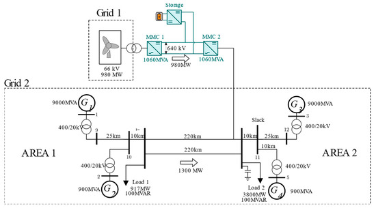
Figure 8.
Two-area power system for inter-area power oscillation damping study.
In the proposed configuration, the triggering event is a fault on one of the two transmission lines and its isolation. As a result, inter-area oscillations appear due to a large amount of power being transmitted through only one long line. Synchronous machines oscillate at 0.28 Hz with no damping. HVDC links can provide power oscillation damping (POD) without energy storage but, in this case, the power oscillations are reflected on the other side of the HVDC link, which is not appropriate if the HVDC link is not an interconnector but transfers power from a wind farm. For an OWF, the HVDC link cannot be controlled for damping oscillations because it could create oscillations at the OWF side, as the active power of both converter stations cannot be decoupled. The goal of energy storage is to act as a firewall. In other words, the addition of energy storage on the dc side of an HVDC link can allow damping of the oscillations of a network, without being perceptible on the other side of the link (the wind farm in this case). Note that, here, the power oscillation damping is provided by the VSC converters of the HVDC link, and it is superimposed to the existing power flow.
3.2. Fast Frequency Response between Two Asynchronous Networks
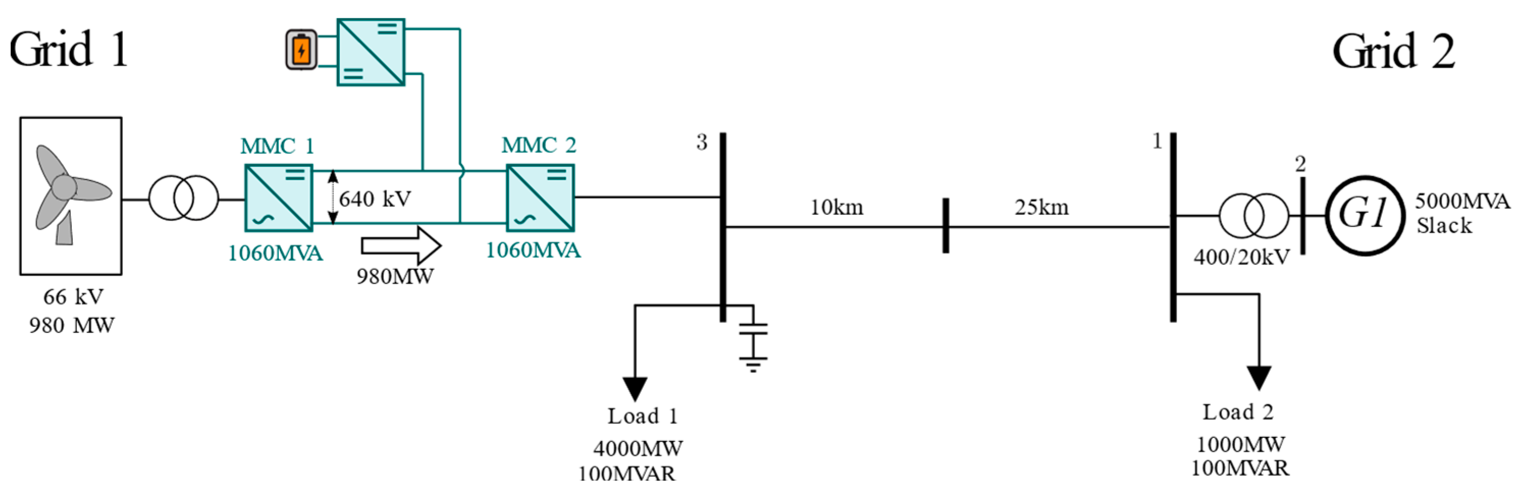
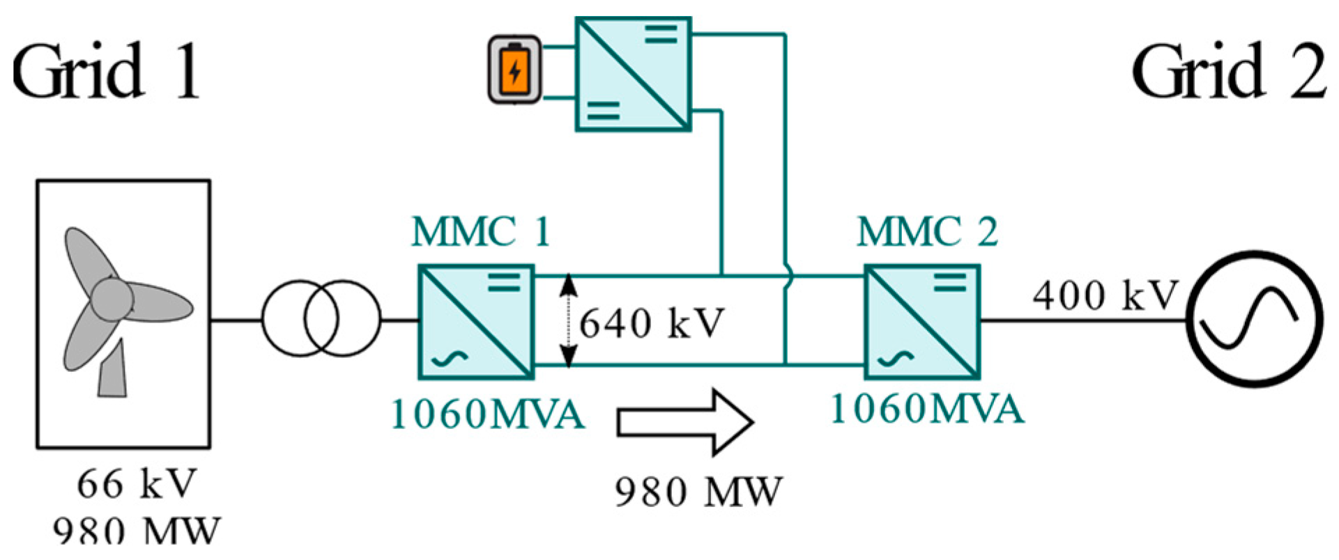
Figure 9 shows the use case to validate the provision of fast frequency services from energy storage connected to HVDC terminals. It consists of a point-to-point HVDC link between an OWF and an ac grid. The latter is modelled with a 5000 MVA generator equipped with a PSS and an AVR and a transmission line between two different buses. A load is connected to each bus. The fast frequency response is provided by the HVDC converter station, while the scenario corresponds to the connection of load 2 (P = 1000 MW and Q = 100 MVAR). It causes a power imbalance and a frequency disturbance on grid 2 that requires an additional active power injection. The objective of this simulation is to use the energy storage to provide the required fast frequency response (FFR) service to ac network 2, while remaining unnoticeable from ac grid 1’s standpoint. This means that the power exchanged between both converter stations remains constant while the additional power is only provided to ac grid 2 by MMC2.

Figure 9.
Use case for fast frequency response studies.
3.3. Offshore Wind Power Smoothing
In the last case study, the same offshore wind farm and HVDC system as in previous use cases are considered, but in this case, fluctuations in power are considered. Indeed, wind turbines can present eigenmodes that may lead to oscillations (~0.1–0.3 Hz). The average power transferred to the grid is 980 MW, and the aim of energy storage is to avoid power oscillations in grid 2. As oscillations can occur for long durations, this functionality must be maintained in steady state. Furthermore, the service provided by the energy storage must remain imperceptible from the wind farm’s standpoint. The ac system is modelled, in this case, as an ideal voltage source, as shown in Figure 10.
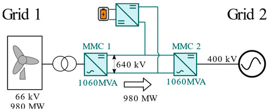
Figure 10.
Use case for offshore wind farm power smoothing studies.
3.4. System Requirements for Each Use Case
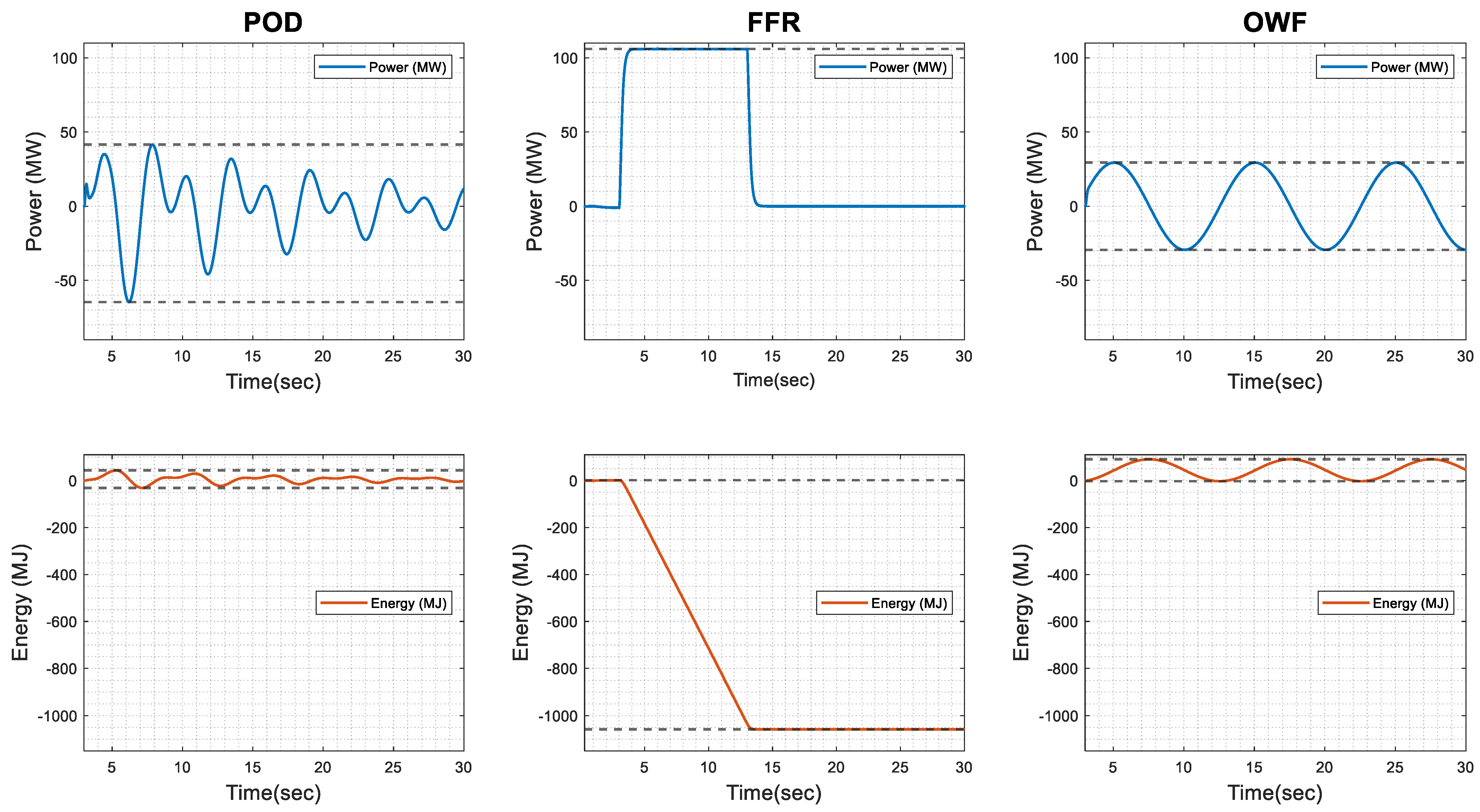
In this subsection, the amount of energy and the power required for energy storage to provide these services are determined. From this perspective, each use case was simulated. Note that in those simulations, the energy storage was modelled as a controllable current source, meaning a power converter connected to an ideal current source. This method allows us to investigate the energy/power requirements from a power system standpoint before carrying out the sizing of the solution. Thus, Table 1 shows the main requirements for the three ancillary services. It shows the maximum energy variation that corresponds to the minimum energy to be stored. In addition, the peak power and average power are provided. Note that the worst oscillation is considered in case of oscillating signals. Figure 11 shows the power and energy requirements for the energy storage system for the three case studies.

Table 1.
Main characteristics of the studied services.
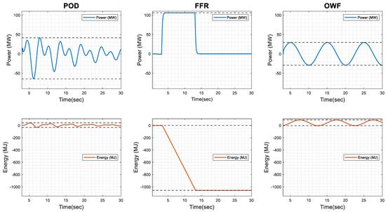
Figure 11.
Power and energy variation requirements for the three considered ancillary services.
As observed, both FFR and POD require a time support of less than 20 s, while OWF power smoothing should be maintained for several dozens of minutes (cf. Section 3.3). However, this corresponds to a repetitive power injection with a zero-energy balance, meaning that the focus can be directed to one cycle for sizing. Note that this service also requires a lower peak power than the other two. Regarding the energy required, it can greatly vary by a factor of 10 from one service to another. Nonetheless, the energy storage capabilities of the studied services remain lower than the traditional bulk energy storage services. Therefore, regarding these observations, it is obvious that the impact on the power conversion and the energy storage sizing will differ. This may call into question the relevance of sizing a solution for a given service.
4. Results
This section presents the obtained parameters for the energy storage system and the single-branch energy storage submodule converter. As described in Section 2, simulations of the three case studies presented in Section 3 were first carried out in the EMT domain to obtain the specifications for the design of the solution. These mission profiles (cf. Figure 11), to address grid needs, allow us to first size the energy storage system and its power conversion system. In a second step, simulations were carried out again in the EMT domain, with a complete model (Model A), to validate that the sized system complies with requirements.
4.1. System Design Results
The characteristics of the storage technology and the main elements of the branch energy storage submodules such as passive components and constraints on switches can be determined from the sizing process. Table 2 shows the obtained design for the single branch of energy storage submodules for the three cases studies.
Table 2.
Comparison for a single-branch ES-SM for different ancillary services.
From the outset (Section 3), it was known that the FFR service has higher power and energy requirements. POD and OWF power smoothing services represent only 7% and 8% of the energy needed for FFR services. This means that an energy storage system designed for this application can deal with the two others (provided that services are not required at the same time). Note that the energy stored is twice the energy indicated in Table 1. This is to be able to provide the load profile in both power directions.
Regarding the main half-bridge in energy storage submodules, the same switches can be used. This is because POD and FFR services have almost the same peak power. Although OWF application requires only one-third of FFR peak power, it is difficult to find the same technology of switches (6.5 kV) with the same voltage rating but a lower current capability. To have a better use of switches in OWF applications, 1.7 kV switches, with lower current rating, can be used. Nonetheless, it will inevitably increase the total number of energy storage submodules and thus the number of components (switches, sensors…). In opposition, from the dc-dc converter interface standpoint, the current rating of the switches is not similar because of the voltage variation of the energy storage element. It makes the current flowing through it much more sensitive to the requested power according to the depth of discharge of the energy storage. That is why the dc-dc converter for FFR requires switches with higher current capability contrary to the OWF case.
The values of the submodule capacitors are relatively close between the three options. Nonetheless, it remains greater for the FFR case study because of higher constraints as its sizing depends on power (~current) requirements.
Finally, regarding the energy storage, it is logical that FFR application requires a higher number of modules. This is because more energy must be stored per submodule. Inevitably, the volume and weight of a submodule would be bigger. However, no more than 70% of this energy can be potentially used for upward or downward services, contrary to POD and OWF applications, as shown by the utilization factor. In opposition, for POD and OWF smoothing needs, the size is not directly related to the stored energy: less than a quarter of the total stored energy is used, while an optimum amount would be around 75% for a supercapacitor (~half-voltage). The size is actually constrained by the required power (and current). This is due to the gap between the time constants (<5 s) required by these two services and the selected storage element. Indeed, it is difficult to find a technology that is tailor-made with a very low time constant and that can repeat this cycle several times in a row.
4.2. Simulation Results
In this subsection, the performed sizing approach is verified through new simulations in the EMT domain. The same simulations are conducted as previously, but the energy storage system is no longer modelled with Model B, using a controllable current source, but with Model A, which is a more detailed model (cf. Section 2.4), involving a dc-dc converter connected to a capacitor in series with resistance.
4.2.1. Inter-Area Power Oscillation Damping
This case study is to show that energy storage connected to an HVDC system can help to damp inter-area oscillations in one grid, without disturbing the grid on the other side of the HVDC link (cf. Section 3.1). For that purpose, a comparative analysis is carried out to shed light on the impact of the energy storage (Figure 12).
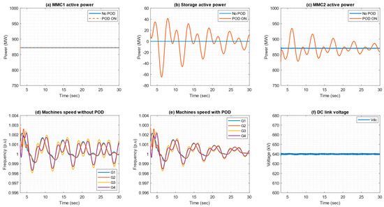
Figure 12.
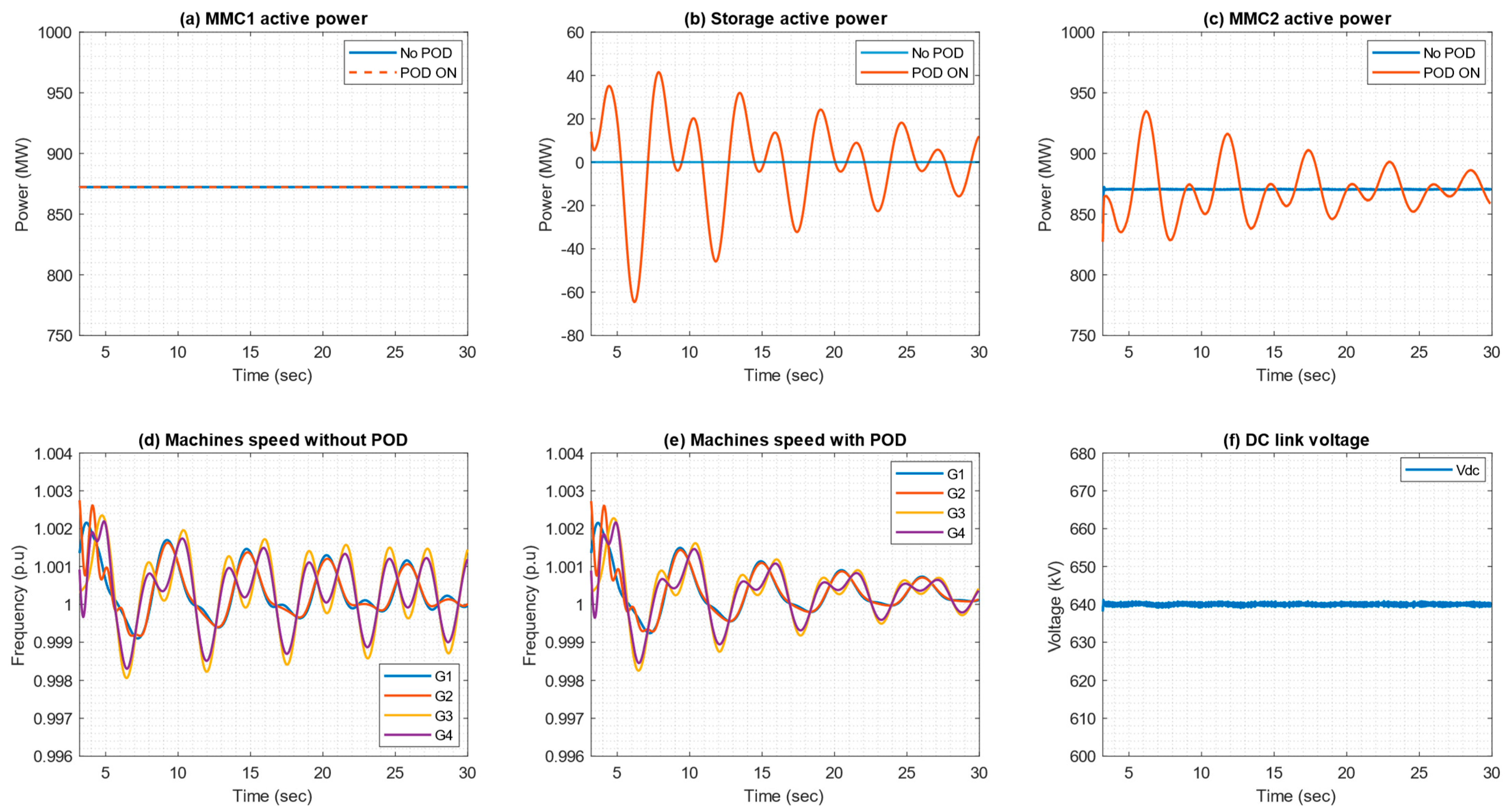
POD results with (a) ac active power of MMC1 (wind turbine side); (b) dc storage active power; (c) ac active power of MMC2 (grid side). (d) Machine speed without POD. (e) Machine speed with POD; (f) dc link voltage during POD provision.
In the first simulation, the storage is not active and the HVDC link is not controlled to damp the oscillations in the onshore grid. In the second simulation, the HVDC link is controlled to damp oscillations, and the additional power is provided by the energy storage. Figure 12a–c presents the active power injected by both converter stations of the HVDC link and the dc storage during simulations. Figure 12d,e shows the speed (~frequency) of the machines in grid 2 where the event occurs.
First, oscillations are poorly damped when no POD control and energy storage are implemented. However, this situation can be avoided by adding an energy storage system. As can be seen in Figure 12, the integration of energy storage allows a firewall effect: oscillations on one side of the HVDC link can be addressed without disturbing the power exchange. So, the POD action on the other side of the HVDC link (OWF) is unnoticeable. This is because the additional active power is provided by the storage and no energy is extracted from the OWF (or a healthy power system). Figure 12b confirms this by displaying the active power released by the energy storage.
Figure 13 presents the results of the energy element of one energy storage submodule of the single branch. Note that we zoom in on the worst swing, at the beginning of the event, from 3 to 7 s, as it was used to design the energy storage system.
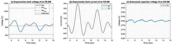
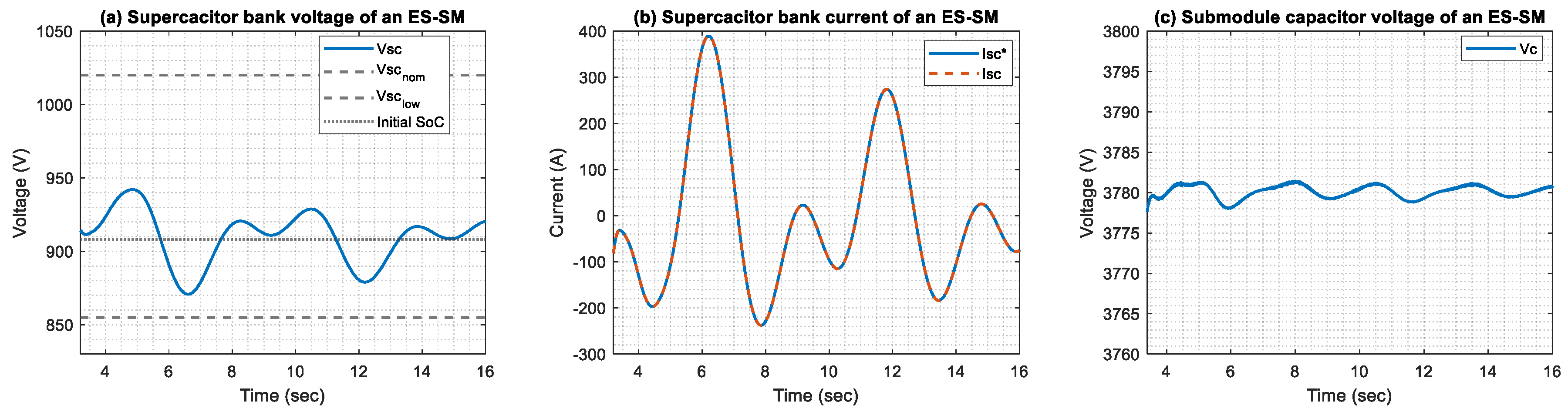
Figure 13.
POD results with (a) the supercapacitor bank voltage of an ES-SM; (b) the supercapacitor bank current of an ES-SM; (c) the submodule capacitor voltage of an ES-SM.
Figure 13a shows the voltage across the supercapacitor bank of an energy storage submodule. As observed, the voltage does not exceed the nominal value of the pack (i.e., 1020 V), while only a small fraction of the total stored energy is used. As a reminder, this is due to the current limitation within the bank that does not allow for a reduction in the number of modules in series (~voltage) of the single branch. To provide more information, Figure 13b displays the current through the supercapacitor bank. As observed, the peak current is almost 400 A, which is in line with the value indicated in Table 2 during the analytical design. Furthermore, making the root mean square of the current curve between 5.8 and 7.9 s, the rms current is approximately 280 A. This is in accordance with the maximum continuous current considered for the design. Note that there are small differences between the nominal voltage and the maximum supercapacitor voltage in Figure 13a. This is because the design is carried out to ensure the worst energy variation in both power directions, meaning the swing between 5.8 and 7.9 s. However, there is another small swing just before. Finally, Figure 13c depicts the voltage at the submodule capacitor. As seen, its voltage kept constant; only negligible transients occur.
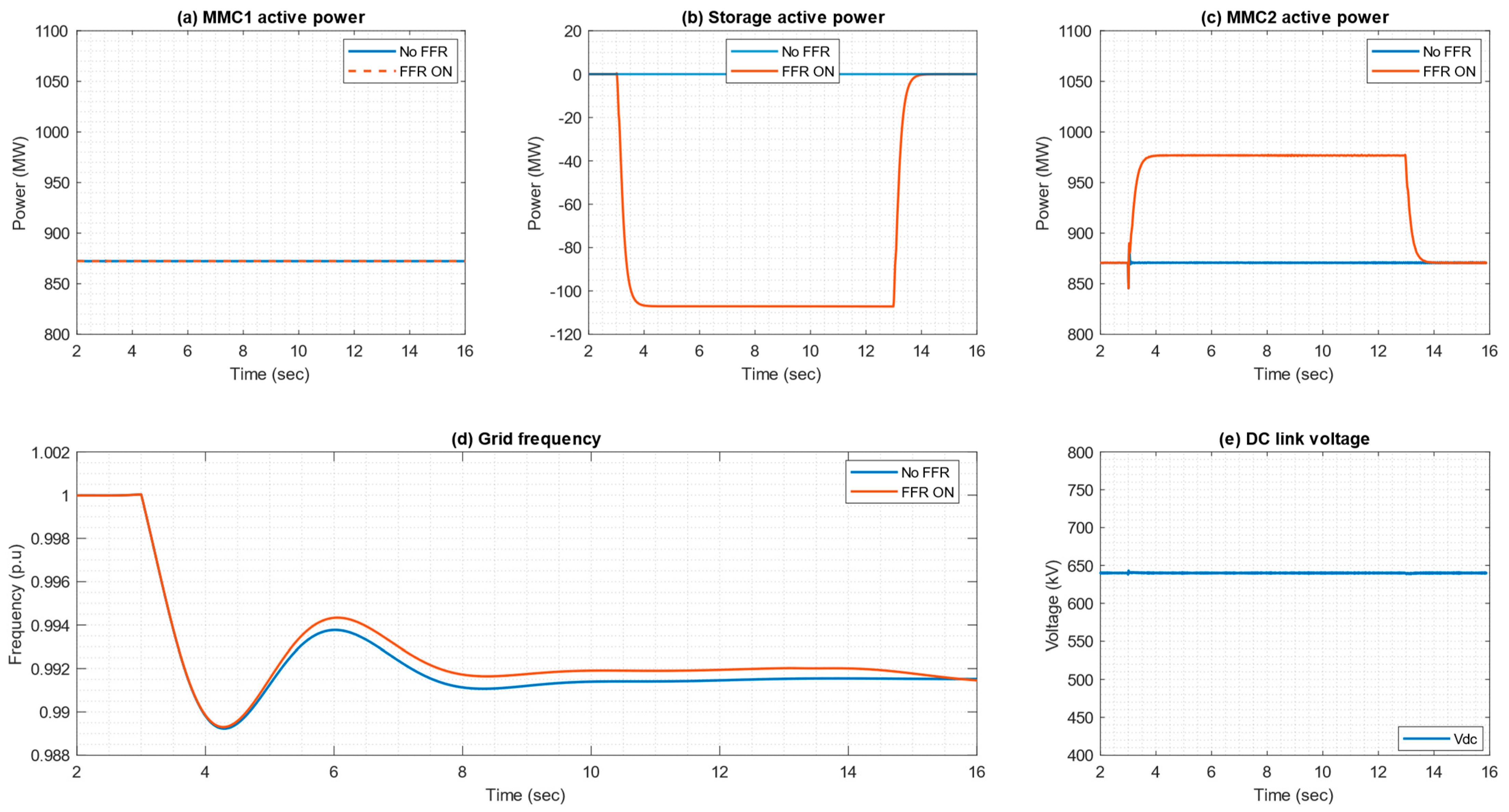
4.2.2. Fast Frequency Response
This section presents the results for fast frequency response from the single branch of energy storage submodules after a sudden load connection after 3 s (cf. Section 3.2). Figure 14c illustrates that an additional power injection is made by MMC2 to grid 2, where the disturbance occurs. The gap is bridged by the proposed energy storage. Note that, at the same time, the power exchange between both converter stations is not influenced, as shown in Figure 14. The dc link voltage is well maintained (cf. Figure 14e). This also means that grid 1 is not disturbed as no power variation occurs. This validates the opportunity to offer ancillary services without disturbing the active power provision by the OWF. Finally, Figure 14d depicts the speed of the synchronous machine, meaning the system frequency. As observed, the fast power injection prevents the drop in frequency within approximately one second and reduces the nadir regarding the conventional solution.
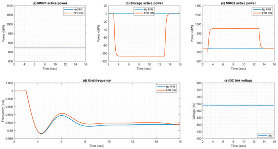
Figure 14.
FFR results with (a) ac active power of MMC1 (wind turbine side); (b) dc storage active power; (c) ac active power of MMC2 (grid side); (d) onshore grid frequency; and (e) dc link voltage during FFR provision.
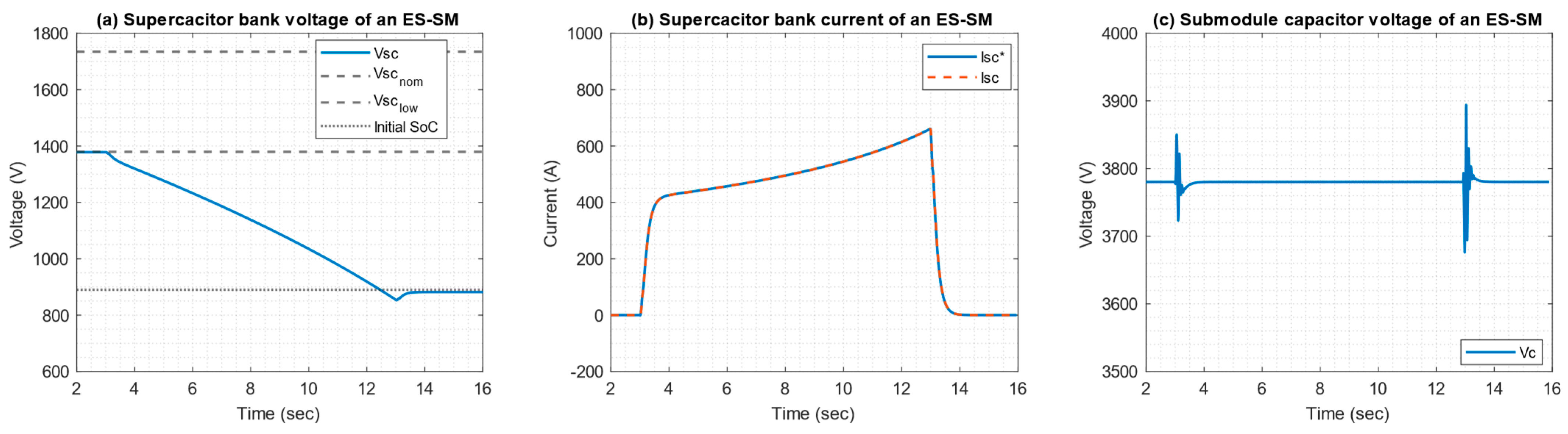
Then, Figure 15 presents the results for one energy storage submodule during this event, where power should be provided to the grid. In Figure 15a, the voltage across the energy storage of a submodule is depicted. One can observe that the end of discharge voltage is near 885 V. This is almost half the nominal voltage of the supercapacitor pack (~1734 V). This confirms that more than 70% of the total energy stored can be used if the storage is designed for this application for upward and downward services. Therefore, the discharge phase started from 1380 V, and not from the nominal voltage.
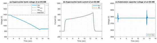
Figure 15.
FFR results with (a) the supercapacitor bank voltage of an ES-SM; (b) the supercapacitor bank current of an ES-SM; (c) the submodule capacitor voltage of an ES-SM.
To conclude, the evolution of the current over time within the supercapacitor bank is presented in Figure 15. As shown, the peak value is close to the expected value (660 A) in Table 2 by computing the rms current, a value of 499 A. Knowing that a storage system is composed of two branches in parallel (cf. Table 2), this means a continuous current of 250 A flows per branch. This is under the maximum continuous current considered for design, which is 285 A (cf. Section 2.5). Both figures confirm that the design of the energy storage element is correct. Finally, Figure 15c shows that the ES-SM capacitor voltage is well maintained at a constant value.
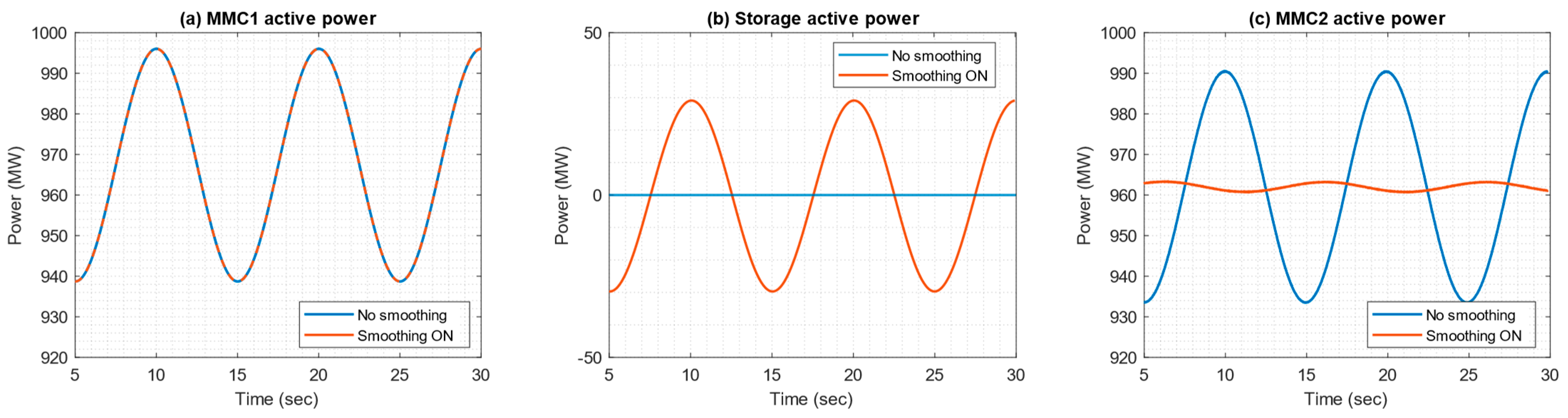
4.2.3. OWF Power Smoothing
In this last case study, the aim is to smooth the intrinsic power oscillations produced by wind turbines, with a frequency between 0.1 and 0.3 Hz that stands for 3% of the total power of the OWF park (cf. Section 3.3). Note that this service should be provided in a steady state.
First, Figure 16 presents the results at the system level. Two simulations are compared to emphasize the benefits of the proposed solution: an HVDC link without and with energy storage to smooth power oscillations. Figure 16a,c show the active power at both converter stations. As shown, smooth power is provided by the onshore MMC when an energy function is implemented. Thus, parasitic oscillations from the OWFs are not transmitted to the grid and directly buffered by the energy storage, as confirmed by Figure 16c.

Figure 16.
OWF power smoothing results with (a) ac active power of MMC1 (wind turbine side); (b) dc storage active power; (c) ac active power of MMC2 (grid side).
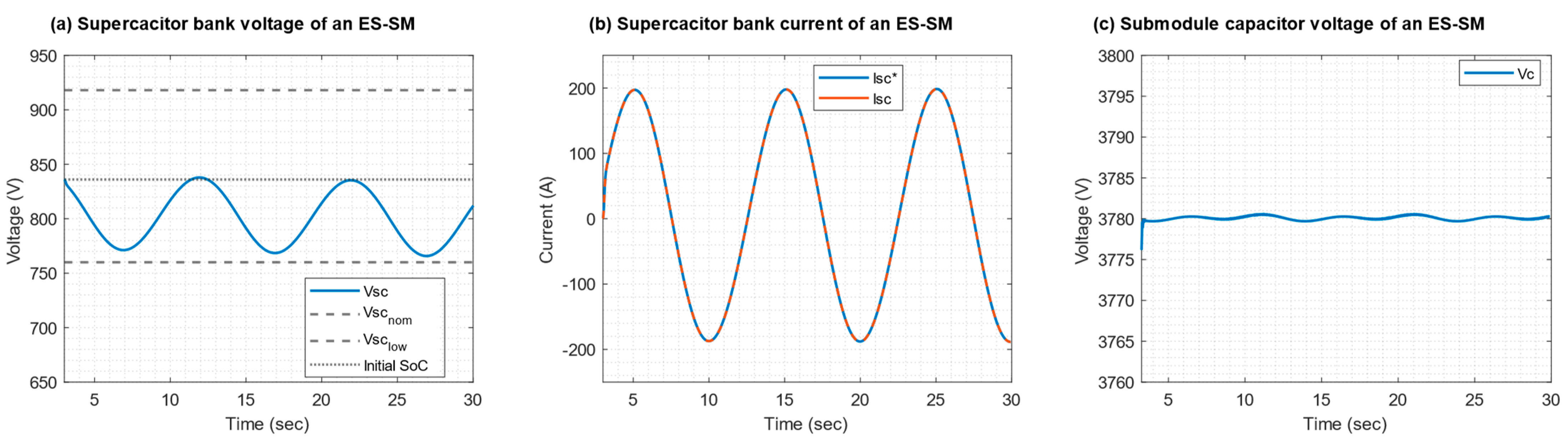
To conclude, Figure 17a,b depicts the evolution over time of the voltage and the current of the supercapacitor bank of an energy storage submodule. As can be observed during the first swing, the energy storage voltage decreases to approximately 770 V. Note that the upper and lower voltage boundaries of the supercapacitor bank to ensure upward and downward services are indicated in the figure. The lower boundary is not crossed, meaning that the design is correct. This is confirmed in Figure 17b; the peak current reaches 200 A, which corresponds to the value mentioned in Table 2, while the rms value of the current is 141 A, which is lower than the limit of 172 A considered for the design (cf. Section 2.5 and Table 2).
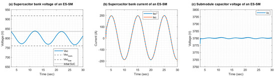
Figure 17.
OWF power smoothing results with (a) the supercapacitor bank voltage of an ES-SM; (b) the supercapacitor bank current of an ES-SM; (c) the submodule capacitor voltage of an ES-SM.
Nonetheless, one can remark that the state of charge of the solution drifts slightly over time, while this service should be provided in a steady state. This is due to the losses within the system (that is to say, the supercapacitor bank and the power converter) which are not compensated. This means that an additional loop must be included in the control scheme of the single branch of energy storage submodules to take it into account.
To conclude, Figure 17c presents the voltage at the submodule capacitor, which is correctly controlled during the service provision. It shows the effectiveness of the proposed control scheme.
5. Conclusions
This paper investigates an offshore wind farm connected to the shore through an HVDC system including a converter embedding energy storage elements. Energy storage is used to provide services to the AC system (power oscillation damping, fast frequency response, wind farm power smoothing) without changing the point of operation of the wind farm. For each considered service, preliminary design of the converter and of the energy storage is achieved according to the methodology introduced in this paper. It has been shown that an energy storage converter connected to DC terminals can provide the expected services without disturbing the operation of the wind farm. Furthermore, it is also demonstrated that the proposed methodology allows us to design solutions complying with the requirements of the three expected services. These are quite different. The peak power is between 29.4 MW (smoothing) and 106 MW (FFR) while the required energy is in the range of 74.6 MJ (POD) to 1059 MJ (FFR). For the three services, the sizing process led to realistic components (190 SMs made with 6.5 kV IGBT switches less than 700 A), corresponding to technologies and ratings used in HVDC applications. Each energy storage submodule includes between 266 and 1006 L of energy storage elements, which is also feasible regarding the size of actual valve halls in HVDC applications (even if the calculated volume is the sum of the volume of each energy storage elements, the total being slightly larger).
POD and offshore wind farm smoothing present poor utilization factors. It means that the supercapacitors are sized to provide the required power but more energy than needed is stored. However, this opens the possibility of the use of this energy for other services.
It should be noted that, to provide these services, the MMC connected to the shore should be operated at an initial power that is lower than its maximal power to keep a margin to provide additional power during transient operation.
The interest shown in this paper for a wind farm connected to the shore through HVDC can be explored for any HVDC system, including a link between asynchronous areas or a multi-terminal DC system. The motivation to use HVDC connected energy storage in this paper can be generalized as providing services to any AC system to which the HVDC system is connected without disturbing the other AC systems. From this perspective, the energy storage converter can be connected close to any of the terminals, or wherever it is cost-effective, to provide services to all the connected areas, mutualizing the energy storage for different areas. It can also be used to support the DC voltage stability in case of events like a converter trip.
Note that for a real application, each project is specific. Thus, it should be studied with a realistic model of the systems to which the energy storage converter is connected. The method presented here has been demonstrated with simplistic AC models, but it can be used for realistic use cases. One can also remark that the general methodology proposed in this paper can be reused for different energy storage technologies, such as batteries, by adapting the design stage of the energy storage submodules. Thus, it would also enable a comparison among different energy storage technologies. To conclude, it is well known that energy storage and modular power converters will be key technologies to support the mutation of power systems; therefore, it would also be important to assess the environmental impact of such a solution as well as its economic cost [28]. Also, DC/DC converters to interface energy storage elements and HVDC systems, as presented in [17] or [22], are currently at low levels of technological readiness. Further research works are needed on this topic to push them closer to the market.
Author Contributions
Conceptualization, F.E., J.S.-B. and F.M.; methodology, F.E. and F.M.; validation, H.B.; formal analysis, F.M.; investigation, J.-C.G.-T. and P.R.; resources, A.B. and X.B.; writing—original draft preparation, F.E., J.S.-B., H.B. and F.M.; writing—review and editing, J.-C.G.-T., A.B., P.R. and X.B.; supervision, F.M. and X.B.; project administration, F.M. and A.B.; funding acquisition, X.B. All authors have read and agreed to the published version of the manuscript.
Funding
This research was funded by RTE and by a grant overseen by the French National Research Agency (ANR) as part of the “Investissements d’Avenir” Program (ANE-ITE-002-01).
Data Availability Statement
The study did not report any data.
Conflicts of Interest
The authors declare no conflicts of interest.
Nomenclature
| The dc component of a variable | |
| Equivalent ES-SM capacitance | |
| Capacitance of a supercapacitor module | |
| ES-SM capacitance | |
| Capacitance of the supercapacitor bank of an ES-SM | |
| Equivalent capacitance of the equivalent supercapacitor bank | |
| Ratio between the voltage and the nominal voltage of a supercapacitor bank | |
| Average duty cycle of the equivalent dc-dc converter | |
| Equivalent series resistance of a supercapacitor bank | |
| Equivalent series resistance of a supercapacitor module | |
| Equivalent ES-SM capacitor current | |
| Dc current flowing through a single branch | |
| Energy storage current of an ES-SM that flows toward an ES-SM capacitor | |
| Index for an ES-SM in the chain link | |
| Branch inductor | |
| Equivalent ES-SM filtering inductor | |
| Averaged modulation index | |
| Number of ES-SMs in a single branch | |
| Number of modules in series in a supercapacitor bank of an ES-SM | |
| Number of branches in parallel in a supercapacitor bank of an ES-SM | |
| Total number of modules in a supercapacitor bank of an ES-SM | |
| Dc power provided by the storage device | |
| Power provided by the storage device | |
| Branch resistance | |
| Equivalent ESR of the equivalent supercapacitor | |
| Equivalent ES-SM resistance | |
| Equivalent inserted voltage of the stack of ES-SMs | |
| Equivalent ES-SM capacitor voltage | |
| DC link voltage | |
| Nominal voltage of a supercapacitor module | |
| Voltage of a supercapacitor bank | |
| ES-SM capacitor voltage | |
| Energy stored within a supercapacitor bank |
References
- Alhomsi, H.; Linke, F.; Westermann, D. AC System Restoration Using Embedded MT-HVDC. In Proceedings of the IEEE PES ISGT Europe, Novi Sad, Serbia, 10–12 October 2022. [Google Scholar]
- Spallarossa, C.; Merlin, M.; Green, T. Augmented inertial response of Multi-Level Converters using internal energy storage. In Proceedings of the IEEE ENERGYCON, Leuven, Belgium, 4–8 April 2016. [Google Scholar]
- Gonzalez-Torres, J.-C.; Mourouvin, R.; Shinoda, K.; Zama, A.; Benchaib, A. A simplified approach to model grid-forming controlled MMCs in power system stability studies. In Proceedings of the IEEE PES ISGT Europe, Espoo, Finland, 18–21 October 2021. [Google Scholar]
- Rokrok, E.; Qoria, T.; Bruyere, A.; François, B.; Haibo, Z.; Belhaouane, M.; Guillaud, X. Impact of grid-forming control on the internal energy of a modular multilevel converter. In Proceedings of the EPE ECCE Europe, Lyon, France, 7–10 September 2020. [Google Scholar]
- Groß, D.; Sánchez-Sánchez, E.; Prieto-Araujo, E.; Gomis-Bellmunt, O. Dual-Port Grid-Forming Control of MMCs and Its Applications to Grids of Grids. IEEE Trans. Power Deliv. 2022, 37, 4721–4735. [Google Scholar] [CrossRef]
- CIGRE Working Group B4.84. Feasibility Study and Application of Electric Energy Storage Systems Embedded in HVDC and STATCOM Systems; CIGRE Technical Brochure 935: Paris, France, 2024. [Google Scholar]
- Farivar, G.; Manalastas, W.; Tafti, H.; Ceballos, S.; Sanchez-Ruiz, A.; Lovell, E.C.; Konstantinou, G.; Townsend, C.; Srinivasan, M.; Pou, J. Grid-Connected Energy Storage Systems: State-of-the-Art and Emerging Technologies. Proc. IEEE 2023, 111, 397–420. [Google Scholar] [CrossRef]
- Frey, K.; Garg, M.; Morgenstern, R.; Platt, N.; Spahic, E. Provision of fast frequency response by SVC plus frequency stabilizer. In Proceedings of the IET ACDC, Coventry, UK, 5–7 February 2019. [Google Scholar]
- Meng, L.; Heydari, R.; Bai, H.; Hasler, J.-P.; Ingeström, G.; Kheir, J.; Owens, A.; Svensson, J. Energy Storage Enhanced STATCOM for Secure and Stable Power Grids. In Proceedings of the CIGRE Session, Paris, France, 28 August–2 September 2022. [Google Scholar]
- Postiglione, G.; Anderotti, M.; Borghetti, G.; Finotti, C.; Pacchioni, M.; Ripamonti, M.; Lacerda, V.A.; Bellmunt, O.G.; Araujo, E.P.; Labady, A. An improved modular STATCOM topology equipped with short-time energy storage and grid forming control for HV network voltage and frequency regulation. In Proceedings of the CIGRE Session, Paris, France, 25–30 August 2024. [Google Scholar]
- Avdiaj, E.; Lindner, M.; Schöll, C.; Beerten, J. Design of an MMC-based grid-forming STATCOM with DC supercapacitors for energy storage. In Proceedings of the CIGRE Colloquium, Vienna, Austria, 12–14 September 2023. [Google Scholar]
- Errigo, F.; de Oliveira Porto, L.; Morel, F. Design Methodology Based on Prebuilt Components for Modular Multilevel Converters with Partial Integration of Energy Storage Systems. Energies 2022, 15, 5006. [Google Scholar] [CrossRef]
- Judge, P.; Green, T. Modular Multilevel Converter with Partially Rated Integrated Energy Storage Suitable For Frequency Support and Ancillary Service Provision. IEEE Trans. Power Deliv. 2019, 34, 208–219. [Google Scholar] [CrossRef]
- Blatsi, Z.; Judge, P.; Finney, S.; Merlin, M. Blackstart Capability of Modular Multilevel Converters From Partially-Rated Integrated Energy Storage. IEEE Trans. Power Deliv. 2023, 38, 268–276. [Google Scholar] [CrossRef]
- Tayyebi, A.; Dijkhuizen, F.; Larsson, M.; Johansson, N.; Berggren, B.; Alves, R.; Gohil, G.; Kannan, V.; Hafner, Y.-J. On the role of energy storage and grid-forming control in the future HVDC systems. In Proceedings of the CIGRE Session, Paris, France, 25–30 August 2024. [Google Scholar]
- Errigo, F.; Morel, F.; De Vienne, C.M.; Chédot, L.; Sari, A.; Venet, P. A Submodule with Integrated Supercapacitors for HVDC-MMC providing Fast Frequency Response. IEEE Trans. Power Deliv. 2022, 37, 1423–1432. [Google Scholar] [CrossRef]
- Pinheiro, D.L.M.; Errigo, F.; Morel, F. A DC/DC converter for centralized energy storage in HVDC applications. In Proceedings of the IET PEMD, Nottingham, UK, 10–13 June 2024. [Google Scholar]
- HVDC-WISE Project. Deliverable 4.1: Identification of Key Technologies, Potential Benefits and Restrictions. 2023. Available online: https://hvdc-wise.eu/resources/ (accessed on 5 August 2024).
- Bharadwaj, C.A.; Maiti, S. Modular multilevel E-STATCOM considering distributed energy storage at the dc link. In Proceedings of the IEEE PIICON, Bikaner, India, 25–27 November 2016. [Google Scholar]
- Montesinos-Miracle, D.; Massot-Campos, M.; Bergas-Jane, J.; Galceran-Arellano, S.; Rufer, A. Design and Control of a Modular Multilevel DC/DC Converter for Regenerative Applications. IEEE Trans. Power Electron. 2013, 28, 3970–3979. [Google Scholar] [CrossRef]
- Mahr, F.; Jaeger, J.; Henninger, S.; Rubenbauer, H. Hybrid Energy Storage System for MVDC-Grids. In Proceedings of the EPE ECCE Europe, Lyon, France, 7–11 September 2020. [Google Scholar]
- Sau-Bassols, J.; Morel, F.; Errigo, F.; Bekkouri, H.; Gonzalez, J.C.; Benchaib, A. Single branch of energy storage submodules to integrate energy storage devices in HVDC systems. In Proceedings of the 19th International Conference on AC and DC Power Transmission (ACDC 2023), Glasgow, UK, 1–3 March 2023. [Google Scholar]
- Errigo, F.; Gonzalez-Torres, J.-C.; Benchaib, A.; Chédot, L.; Sari, A.; Venet, P.; Morel, F. Modular Multilevel Converter with Embedded Energy Storage for Power Oscillation Damping and Fast Frequency Response—A case study. In Proceedings of the CIGRE Symposium, Ljubljana, Slovenia, 21–24 November 2021. [Google Scholar]
- Saad, H.; Dennetière, S.; Mahseredjian, J.; Delarue, P.; Guillaud, X.; Peralta, J.; Nguefeu, S. Modular Multilevel Converter Models for Electromagnetic Transients. IEEE Trans. Power Deliv. 2014, 29, 1481–1489. [Google Scholar] [CrossRef]
- Alvarez, R.; Pieschel, M.; Gambach, H.; Spahic, E. Modular multilevel converter with short-time power intensive electrical energy storage capability. In Proceedings of the 2015 IEEE Electrical Power and Energy Conference (EPEC), London, ON, Canada, 26–28 October 2015. [Google Scholar]
- Skeleton Products-Supercapacitor Modules. [Online]. Available online: https://www.skeletontech.com/en/supercapacitor-modules (accessed on 22 August 2024).
- Barrade, P.; Rufer, A. Current capability and power density of supercapacitors: Considerations on energy efficiency. In Proceedings of the European Conference on Power Electronics and Applications (EPE), Toulouse, France, 2–4 September 2003. [Google Scholar]
- Campos, A.; Jasi, A.; Vershinin, K.; Dworakowski, P. CO2 Footprint of Medium Voltage DC Solid State Transformer. In Proceedings of the PCIM Europe, Nuremberg, Germany, 11–13 June 2024. [Google Scholar]


Disclaimer/Publisher’s Note: The statements, opinions and data contained in all publications are solely those of the individual author(s) and contributor(s) and not of MDPI and/or the editor(s). MDPI and/or the editor(s) disclaim responsibility for any injury to people or property resulting from any ideas, methods, instructions or products referred to in the content. |
© 2024 by the authors. Licensee MDPI, Basel, Switzerland. This article is an open access article distributed under the terms and conditions of the Creative Commons Attribution (CC BY) license (https://creativecommons.org/licenses/by/4.0/).