Article

A Synchronization Algorithm for MBOC Signal Based on Reconstructed Correlation Function

1
Guangxi Key Laboratory of Precision Navigation Technology and Application, Guilin University of Electronic Technology, Guilin 541004, China
2
Information and Communication School, Guilin University of Electronic Technology, Guilin 541004, China
3
National and Local Joint Engineering Research Center of Satellite Navigation Positioning and Location Service, Guilin 541004, China
4
GUET-Nanning E-Tech Research Institute Co., Ltd., Nanning 530031, China
*
Authors to whom correspondence should be addressed.
Electronics 2024, 13(17), 3375; https://doi.org/10.3390/electronics13173375
Submission received: 15 June 2024 / Revised: 22 August 2024 / Accepted: 24 August 2024 / Published: 25 August 2024
(This article belongs to the Section Circuit and Signal Processing)

Abstract

:
In order to address the ambiguous synchronization problem caused by the multi-peak nature of the autocorrelation function of the modulated signal of the Multiplexed Binary Offset Carrier (MBOC) in the Global Navigation Satellite System (GNSS), a new synchronization algorithm for MBOC signals is presented in this paper, which uses a reconstruction correlation function to effectively handle synchronization ambiguities associated with multi-peak signals. The paper proposes an algorithm for reconstructing the correlation function of the MBOC signal by analyzing its characteristics. The algorithm generates three local auxiliary signals, namely, pseudo-random codes (PRN), BOC(1,1) signals, and MBOC signals, which are correlated with the received signal. By combining the three correlation functions, the algorithm produces a reconstructed correlation function based on reconstruction rules, eliminating side peaks and achieving unambiguous synchronization. Simulation results show that the proposed algorithm in this paper eliminates all side peaks while maintaining a high detection probability, and its deblurring capability is optimal compared to other algorithms. In addition, the discriminant curve shows that the algorithm in this paper successfully eliminates all the mis-locked points, and the slope gain is improved by more than 2.5 dB compared with other algorithms, and the anti-multipath performance of the algorithm in this paper is better than that of other traditional algorithms, such as ASPeCT (Autocorrelation Side-Peak Cancellation Technique).

1. Introduction

MBOC is a new modulation standard proposed by the European Union and the United States and, since the MBOC signal is defined as a modulation in the frequency domain, the time-domain model of this signal can be implemented in a flexible manner depending on the signal amplitude, time and phase [1,2]. There are three main MBOC implementations: the QMBOC (Quadrature Multiplexed Binary Offset Carrier) signals used in BeiDou B1C, the TMBOC (Time-Multiplesed Binary Offset Carrier) signals used in GPS L1C, and the CBOC (Composite Binary Offset Carrier) signal used by Galileo E1B/C [3,4]. Compared with the standard BOC (Binary Offset Carrier) signal, the MBOC signal contains more high-frequency components in its power spectrum and has a larger Gabor bandwidth with narrower correlation main peaks, which makes the MBOC signal have a better tracking accuracy and anti-multipath performance [5,6]. However, the square wave subcarrier modulation introduced by the MBOC signal will cause multiple side peaks in its autocorrelation function and, in the synchronization process, it is easy to incorrectly lock on the side peaks and mis-acquisition occurs, which results in the ambiguous synchronization problem, so it is very essential to design synchronization algorithms that can eliminate the side peaks of the MBOC signal and solve the ambiguous synchronization problem while retaining the superior performance of the MBOC signal.
In order to solve the problem of MBOC signal synchronization ambiguity, scholars at home and abroad have proposed a variety of algorithms used to suppress the interference of the side peaks, so as to eliminate the ambiguity problem and retain the characteristics of the narrowly correlated main peaks of the MBOC signal. The current MBOC signal unambiguous synchronization algorithms are mainly divided into two categories. One is the degradation of the signal, in which the BOC signal can be converted into a BPSK signal for processing because the BOC modulation adds a square wave subcarrier modulation to the BPSK modulation. A typical solution is the BPSK-Like algorithm, where the BPSK-Like algorithm treats the BOC signal as a superposition of two BPSK signals at the positive and negative subcarrier frequencies. It filters the side peaks separately, thus removing the side peaks of the signal. This class of solutions is represented by two main algorithms, the single-sideband processing algorithm proposed by Fishman and Betz in [7] and the double-sideband processing algorithm proposed by Martin and Heiries in [8]. Although the BPSK-Like algorithm can successfully remove the ambiguities existing in the signal acquisition tracking process, it needs to add additional filter resources in the implementation process, and the use of the single-sideband processing algorithm or double-sideband processing algorithm will result in 3 dB and 1 dB energy loss, respectively [9], which increases the difficulty of receiving and processing the weak signals, and the double-sideband processing algorithm will have additional frequency conversion processing, while the BPSK-Like algorithm results in widening of the acquisition correlation peaks without retaining the advantage of the narrow correlation of the BOC signal, and its code tracking accuracy decreases [10]. The other category is to achieve unambiguous synchronization by designing some special local auxiliary codes to correlate with the received signal, and then designing reconstruction rules based on the characteristics of the resulting correlation function to construct a new correlation function without side peaks [11]. Currently, commonly used local auxiliary codes include pseudo-random codes, BOC signals, and special-order codes. The MBOC signal is treated as a BOC(1,1) signal in [12], discarding the high frequency components present in the MBOC signal, resulting in a loss of energy. In [13,14], multiple correlation functions are generated by splitting the locally generated subcarrier pulses and then correlating them with the received signal, and different reconstruction rules are designed according to the symmetric and translational properties present in the multiple correlation functions obtained, so as to achieve unambiguous tracking of the CBOC signal and the TMBOC signal, respectively; however, both algorithms are designed to increase the implementation complexity at the expense of improving the tracking performance. In [15], an unambiguous tracking algorithm for sinusoidal BOC signals and CBOC signals is proposed, which derives a generic correlation function model for BOC signals based on the shape code vectors, and designs the unambiguous correlation reconstruction rules according to its characteristics, to obtain the reconstructed correlation function that completely eliminates the side peaks and preserves the narrow correlation peaks, which is compared with the traditional method, and the performance of the traditional method has been improved in all aspects. In [16], a synchronization method for BOC(kn,n) signal and CBOC signal is proposed. A segmentation of the signal autocorrelation function is achieved by dividing the locally generated signal according to the integer multiple of the modulation order, and synchronization is achieved by designing reconstruction rules, but the method is flawed in terms of computational complexity. A tracking method for designing local auxiliary codes using only the BOC(6,1) component of the TMBOC signal is proposed in [17]. In summary, although the above algorithm can eliminate the side peaks existing in the signal correlation function, thus solving the ambiguous problem existing in the signal reception and enhancing the synchronization performance of the signal, there are defects, in that the applicability of the algorithm is weaker and only applies to the case of CBOC signals or TMBOC signals, or the implementation is more complicated, the local auxiliary code is more difficult to generate, and the algorithm has a large computational complexity.
To solve the above problems, in this paper, an unambiguous synchronization algorithm for MBOC signals is proposed. The method correlates the three local signals with the received signal by generating pseudo-random codes, BOC(1,1) signals, and MBOC signals, designs the reconstruction rules according to the properties between the correlation functions, and finally obtains the reconstructed correlation function that eliminates the side peaks. The simulation results reveal that, by comparing the performance of various algorithms, this algorithm solves the MBOC signal synchronization blur problem while maintaining a narrower width of the main peak and has certain improvements over traditional methods in terms of detection probability, peak-to-average ratio, and multipath suppression.
The structure of this paper can be divided into the following parts: the second part introduces the MBOC signal characteristics, the principle of the synchronization algorithm, and the analysis of the acquisition tracking loop, and the third part analyses the deblurring validity, the detection probability, the peak-to-average ratio, the phase-identification curves, the anti-multipath, as well as the algorithmic complexity aspects of the synchronization algorithm, to validate the feasibility and the superiority of the synchronization algorithm.

2. Analysis of Synchronization Algorithms

2.1. MBOC Signal

The MBOC signal power spectral density G M B O C ( m , n , ρ ) ( f ) is shown in (1) [3]
G M B O C ( m , n , ρ ) ( f ) = ( 1 ρ ) G B O C ( n , n ) ( f ) + ρ G B O C ( m , n ) ( f )
where G B O C ( n , n ) ( f ) denotes the power spectral density of the low-order BOC signal, G B O C ( m , n ) ( f ) denotes the power spectral density of the high-order BOC signal, and ( 1 ρ ) and ρ denote the proportion of and respectively. At present, the MBOC signal is mainly implemented in the form of MBOC(6,1,1/11), and its specific power spectral density is shown in (2).
G M B O C ( 6 , 1 , 1 / 11 ) ( f ) = 10 11 G B O C ( 1 , 1 ) ( f ) + 1 11 G B O C ( 6 , 1 ) ( f )           = 10 11 ( sin 2 ( π f T c ) sin 2 ( π f T c 2 ) T c [ π f cos ( π f T c 2 ) ] 2 )           + 1 11 ( sin 2 ( π f T c ) sin 2 ( π f T c 12 ) T c [ π f cos ( π f T c 12 ) ] 2 )
where T c denotes the pseudo-random code period.
Equation (3) is a common expression of the BOC signal autocorrelation function, where t r i is an isosceles trigonometric function whose center is at zero, the base width is 2 T s c , and the amplitude is 1 [15].
R B O C = 1 N l 1 = 0 N 1 l 2 = 0 N 1 ( 1 ) l 1 + l 2 t r i ( τ + l 1 T s c l 2 T s c )
According to the Wiener–Khinchin theorem, a Fourier transform relationship exists between the power spectrum and the signal autocorrelation function, from which an autocorrelation function for the MBOC signal is obtained from (4).
R M B O C ( τ ) = F 1 [ G M B O C ( 6 , 1 , 1 / 11 ) ( f ) ] = F 1 [ 10 11 G B O C ( 1 , 1 ) ( f ) + 1 11 G B O C ( 6 , 1 ) ( f ) ] = F 1 [ 10 11 G B O C ( 1 , 1 ) ( f ) ] + F [ 1 11 G B O C ( 6 , 1 ) ( f ) ] = 10 11 R B O C ( 1 , 1 ) ( τ ) + 1 11 R B O C ( 6 , 1 ) ( τ )
where R B O C ( 1 , 1 ) ( τ ) and R B O C ( 6 , 1 ) ( τ ) are the BOC(1,1) and BOC(6,1) signal autocorrelation functions, respectively. The autocorrelation functions of MBOC(6,1,1/11) signal, BOC(1,1) signal and BOC(6,1) signal are illustrated in Figure 1, and it can be observed that, since the BOC(1,1) signal occupies a larger portion of the autocorrelation function of the MBOC signal, the overall trend of the autocorrelation function of the MBOC signal in Figure 1 is in line with that of the BOC(1,1) signal, and the autocorrelation function of the MBOC signal becomes more curved, the span of the main peak is smaller and the peak is sharper and steeper compared to the BOC(1,1) signal under the influence of the BOC(6,1) signal portion, which is conducive to the acquisition of the signal and effectively improves the signal’s ability to resist multipath interference. However, it can be observed from Figure 1 that there are side peaks in the autocorrelation function of the MBOC signal, and the existence of side peaks in the synchronization process will lead to false acquisition and mis-locking, which leads to the problem of ambiguous synchronization, resulting in serious pseudo-ranging measurement errors and making the subsequent positioning results have large deviations, so it is necessary to deal with the side peaks of the MBOC signal to eliminate its adverse effects, in order to solve the ambiguous problem.

2.2. Reconstruction Rules for the Algorithms in This Paper

The idea of reconstructed correlation function generates multiple correlation functions by constructing different local auxiliary codes to correlate with the received signals [18,19] and then, according to the geometric properties between the obtained correlation functions, specific combinations, such as decomposition, translation, and superposition, are used to eliminate or suppress the side peaks of the correlation function of the BOC signals to obtain the reconstructed correlation function that retains a single narrow correlation main peak, thus achieving unambiguous synchronization. Currently, commonly used auxiliary signals include pseudo-random codes, BOC signals and special-order codes, and code correlation reference waveforms. The correlation function can be divided into those based on a combination of multiple correlation functions and those based on autocorrelation function reconstruction. In this paper, a synchronization algorithm for MBOC signals based on reconstructed correlation functions is proposed based on the idea of combined reconstruction of multiple correlation functions.
From Section 2.1, the overall trend of the autocorrelation function of the MBOC signal is consistent with that of the BOC(1,1) signal, so the autocorrelation function of the MBOC signal is approximated as the autocorrelation function of the BOC(1,1) signal in the following theoretical derivation [20,21].
R M B O C / B O C and R M B O C / P R N denote the cross-correlation function of the MBOC signal with the BOC(1,1) signal and the pseudo-random code, respectively. and the specific expressions of the two are shown in (5) and (6).
R M B O C / B O C R B O C / B O C = t r i ( τ ) 1 2 [ t r i ( τ + T c 2 ) + t r i ( τ T c 2 ) ]
R M B O C / P R N R B O C / P R N = 1 2 t r i ( τ + T c 2 ) 1 2 t r i ( τ T c 2 )
R M B O C / P R N is a function symmetrical about the center and R M B O C / B O C is an axisymmetric function, using the symmetry properties of the two to eliminate one-sided side peaks. Specific processing: R M B O C / B O C and R M B O C / P R N are added and subtracted respectively, R 1 is the correlation function obtained after adding the two, and R 2 is the correlation function obtained after subtracting the two, with specific expressions as in (7) and (8).
R 1 = R M B O C / B O C + R M B O C / P R N = t r i ( τ ) t r i ( τ T c 2 )
R 2 = R M B O C / B O C R M B O C / P R N = t r i ( τ ) t r i ( τ + T c 2 )
Both R 1 and R 2 obtained after this process are reconstructed correlation functions with elimination of the unilateral side peaks, and R 3 is obtained by applying (9)
R 3 = | R 1 | + | R 2 | | R 1 R 2 | = 2 t r i ( τ )
The MBOC autocorrelation function was summed with its modulus and the side peaks were eliminated to obtain the correlation function denoted by R 4 . The specific expression is shown in (10)
R 4 = R M B O C + | R M B O C | t r i ( τ ) 1 2 t r i ( τ + T c 2 ) 1 2 t r i ( τ T c 2 ) + | t r i ( τ ) 1 2 t r i ( τ + T c 2 ) 1 2 t r i ( τ T c 2 ) | = 2 t r i ( τ )
Finally, R 3 and R 4 are multiplied to further reduce the width of the detection correlation peak and enhance the height of the main peak to improve the acquisition accuracy, and the final detection correlation function R n e w is obtained, the specific expression is shown in (11)
R n e w = R 3 × R 4
Figure 2a shows the cross-correlation functions R M B O C / B O C , R M B O C / P R N , and CCC, which are obtained by correlating the received signal with three locally generated auxiliary signals: a pseudo-random code, BOC(1,1), and MBOC signals. Among them, R M B O C / B O C and R M B O C are axisymmetric about the set sampling point 600, while R M B O C / P R N is symmetric about the center of sampling point 600. Utilizing this symmetry, operations described by Equations (7) and (8) are performed on R M B O C / B O C and R M B O C / P R N , resulting in R 1 and R 2 , which eliminate the single-sided sidelobe. Then, R 1 and R 2 are processed according to Equation (9) to obtain R 3 , which eliminates the sidelobes on both sides. R 1 , R 2 , and R 3 are shown in Figure 2b. By performing the operation described in Equation (11) on R M B O C , R 4 is obtained, as shown in Figure 2c. Finally, R 3 is multiplied by R 4 , yielding the reconstructed correlation function R n e w . As observed in Figure 2c, the newly reconstructed correlation function R n e w completely eliminates the sidelobes while retaining a narrow single correlation main peak.

2.3. Acquisition Loop Analysis

The block diagram of the MBOC signal synchronization algorithm acquisition structure based on the reconstructed correlation function is illustrated in Figure 3, according to the aforementioned analysis. The algorithm follows a specific process.
(1)
The received signal is mixed with the locally generated carrier to strip the carrier [21].
(2)
Local generation of MBOC signal, BOC(1,1) signal with PRN code.
(3)
The three locally generated auxiliary signals are correlated with the received signal.
(4)
Reconstruction of the three correlation functions obtained in the previous step according to the reconstruction rule to obtain the final detection volume.
The received IF (Intermediate frequency) signal can be expressed as (12) [15]:
S I F ( t ) = 2 P d ( t ) c ( t ) s c ( t ) cos [ 2 π ( f I F + f d ) t ] + n ( t )
where P is the input signal power, d ( t ) is the navigation message, c ( t ) is the pseudo-random code, s c ( t ) is the MBOC signal subcarrier, f I F is the IF, f d is the input signal Doppler frequency, n ( t ) is the noise term. Since the amplitude of the navigation message d ( t ) remains stable and does not fluctuate during processing, its impact can be ignored here. The intermediate frequency signal, after carrier stripping, is cross-correlated with the three locally generated signals. The outputs of the three operations are then integrated and modulus processed, resulting in Equations (13)–(15).
S 1 ¯ ( t ) = | 2 P T s R M B O C / B O C ( Δ τ ) sin c ( π Δ f d T s ) cos ( π Δ f d T s ) + j 2 P T s R M B O C / B O C ( Δ τ ) sin c ( π Δ f d T s ) sin ( π Δ f d T s ) | + N 1 = 2 P T s R M B O C / B O C ( Δ τ ) sin c ( π Δ f d T s ) + N 1
S 2 ¯ ( t ) = 2 P T s R M B O C / P R N ( Δ τ ) sin c ( π Δ f d T s ) + N 2
S 3 ¯ ( t ) = 2 P T s R M B O C ( Δ τ ) sin c ( π Δ f d T s ) + N 3
where T s is the integration duration, Δ τ is the code phase error, Δ f d is the Doppler residual, and N i ( i = 1 , 2 , 3 ) is the Gaussian noise obeying N ( 0 , σ 2 ) . The above (13)–(15) can be abbreviated as (16)–(18)
S 1 ¯ ( t ) = S 1 ( Δ τ , Δ f d ) + N 1
S 2 ¯ ( t ) = S 2 ( Δ τ , Δ f d ) + N 2
S 3 ¯ ( t ) = S 3 ( Δ τ , Δ f d ) + N 3
where S 1 , S 2 and S 3 are the signal parts of S 1 ¯ , S 2 ¯ and S 3 ¯ .
According to the reconstruction rule, if there are M segments of non-correlated cumulative data, the final detection quantity S c can be obtained as in (19)
S c = l = 1 M | S 4 ¯ ( t ) S 3 ¯ ( t ) | = 4 l = 1 M [ | S 3 ( Δ τ , Δ f d ) S 1 ( Δ τ , Δ f d ) | | S 3 ( Δ τ , Δ f d ) S 2 ( Δ τ , Δ f d ) | ] + 4 l = 1 M [ | S 3 ( Δ τ , Δ f d ) N 1 | | S 3 ( Δ τ , Δ f d ) N 2 | + | S 1 ( Δ τ , Δ f d ) N 3 | | S 2 ( Δ τ , Δ f d ) N 3 | ] + 4 l = 1 M [ | N 1 N 3 | | N 2 N 3 | ]
Organizing the above equation gives three parts, the pure signal term, the signal and noise superposition term, and the pure noise term, which are shown below.
Pure signal term
A = 4 l = 1 M [ | S 3 ( Δ τ , Δ f d ) S 1 ( Δ τ , Δ f d ) | | S 3 ( Δ τ , Δ f d ) S 2 ( Δ τ , Δ f d ) | ]
Signal and noise superposition term
H = 4 l = 1 M [ | S 3 ( Δ τ , Δ f d ) N 1 | | S 3 ( Δ τ , Δ f d ) N 2 | + | S 1 ( Δ τ , Δ f d ) N 3 | | S 2 ( Δ τ , Δ f d ) N 3 | ]
Pure noise term
ν = 4 l = 1 M [ | N 1 N 3 | | N 2 N 3 | ]
The probability density function of ν is shown in (23)
P ( v ) = K 0 ( | v | / σ 2 ) π σ 2
0 t μ K v ( t ) d t = 2 μ 1 Γ ( μ + v + 1 2 ) Γ ( μ v + 1 2 )
where K ( · ) is the Type II nth order modified Bessel function and Γ ( · ) is the gamma function. The variance of ν is as in (25)
σ v 2 = v 2 P v ( v ) d v = 64 M σ 4
The Gaussian distribution governs the pure noise term, according to the central limit theorem.
In the absence of signal and only noise, S c obeys a Rayleigh distribution with mean and variance as in (26) and (27)
E ( S c ) = 0
D ( S c ) = 64 M σ 4
At this point, the probability density function of S c is as in (28)
P ( S c ) = S c ( 64 M σ 4 ) 2 exp { S c 2 2 ( 64 M σ 4 ) 2 }
Then the false alarm probability is as in (29)
P f a ( S c ) = V t + p ( S c ) d S c
V t denotes the preset acquisition threshold.
The signal and noise cross term can be expressed as a linear combination of Gaussian noise and a constant. In the case of the simultaneous presence of signal and noise, S c obeys a Rice distribution with mean and variance as in (30) and (31)
E ( S c ) = l = 1 M 8 P s T s 2 sin c 2 ( π Δ f d T s ) ( | R M B O C R M B O C / B O C | | R M B O C R M B O C / P R N | )
D ( S c ) = 64 M σ 4 + 4 l = 1 M σ 2 2 P s T s sin c ( π Δ f d T s ) ( 2 | R M B O C | + | R M B O C / B O C | + | R M B O C / P R N | )
The probability density function and detection probability of S c is as in (32) and (33)
P ( S c ) = S c σ 2 exp { S c 2 + a 2 2 σ 2 } I 0 ( a S c σ 2 )
P f a ( S c ) = V t + P ( S c ) d S c
where a 2 / σ 2 is the signal-to-noise ratio and I 0 ( x ) denotes a type of zero-order modified Bessel function.

2.4. Tracking Loop Analysis

Figure 4 illustrates the block diagram of the tracking loop of the MBOC signal synchronization algorithm on the basis of the reconstruction correlation function. The received signal is first mixed with locally generated in-phase and quadrature carriers to remove the carrier. Meanwhile, the code NCO generates three auxiliary codes: a pseudo-random code, BOC(1,1), and MBOC signals. These auxiliary codes are then subjected to early and late delays. The carrier-stripped received signal is correlated with the early and late auxiliary codes. The resulting correlation outputs are coherently integrated and reconstructed based on the resampling rules outlined in this paper. The reconstructed result serves as the input to the code discriminator. By comparing multiple correlation outputs, the code phase discriminator determines the phase difference between the received signal and the local real-time signal. This phase difference information is then fed back to the code NCO to adjust the local code phase, ensuring accurate signal tracking. A detailed explanation follows.
The input signal is mixed with in-phase and orthogonal two carriers, stripped of the carriers, and then correlated with the early and late auxiliary codes generated by the code NCO, and then cleared by integration to obtain (34) [16]
I E 1 + j Q E 1 = 2 P R M B O C / B O C ( τ d 2 ) e j Δ θ + n I E 1 + j n Q E 1 I E 2 + j Q E 2 = 2 P R M B O C / P R N ( τ d 2 ) e j Δ θ + n I E 2 + j n Q E 2 I E 3 + j Q E 3 = 2 P R M B O C ( τ d 2 ) e j Δ θ + n I E 3 + j n Q E 3 I L 1 + j Q L 1 = 2 P R M B O C / B O C ( τ + d 2 ) e j Δ θ + n I L 1 + j n Q L 1 I L 2 + j Q L 2 = 2 P R M B O C / P R N ( τ + d 2 ) e j Δ θ + n I L 2 + j n Q L 2 I L 3 + j Q L 3 = 2 P R M B O C ( τ + d 2 ) e j Δ θ + n I L 3 + j n Q L 3
where Δ θ and d denote the estimation error of the carrier initial phase and the delay interval between the early correlator and the late correlator, respectively, and n I L i , n I E i , n Q L i and n Q E i (i = 1, 2, 3) are noise terms that follow a Gaussian distribution. Neglecting the noise, according to the reconstruction rule proposed in Section 2.2 combined with (34), the new incoherent phase identification formula after reconstruction can be obtained as (35) by employing the uncorrelated Early Minus Late Power (EMLP) discriminator
D = { ( I E 3 + Q E 3 + | I E 3 + Q E 3 | ) [ | I E 1 + Q E 1 + I E 2 + Q E 2 | + | I E 1 + Q E 1 I E 2 Q E 2 | 2 | I E 2 + Q E 2 | ] ( I L 3 + Q L 3 + | I L 3 + Q L 3 | ) [ | I L 1 + Q L 1 + I L 2 + Q L 2 | + | I L 1 + Q L 1 I L 2 Q L 2 | 2 | I L 2 + Q L 2 | ] } = 2 P [ R n e w 2 ( τ d 2 ) R n e w 2 ( τ + d 2 ) ]
The correlation results are finally adjusted by the code discriminator and the numerically controlled oscillator on the basis of the local code phase for precise tracking.

3. Results and Discussion

In order to verify the performance and generality of the MBOC signal synchronization algorithm based on the reconstruction correlation function, this paper will compare the proposed algorithm with other algorithms in terms of Deblurring Validity, Detection Probability, Peak-to-average Ratio, Discriminative Curve, Anti-multipath and Computational Complexity, and the configurations of some experimental parameters are shown in Table 1.

3.1. Deblurring Validity

To verify the effectiveness of the de-ambiguous MBOC signal synchronization algorithm based on the reconstructed correlation function, simulation experiments are carried out on this paper’s algorithm, and MBOC signal autocorrelation function, ASPeCT [22], SCPC (Sub Carrier Phase Cancellation) [23], Unit Correlation Algorithm [24], and Filtered Correlation Algorithm [25] are also simulated for comparison. Figure 5 illustrates the results of the simulation experiments, normalized to the six correlation functions for ease of comparison. It is clear from Figure 5 that the correlation function obtained by the ASPeCT algorithm and SCPC algorithm fails to eliminate the side peaks completely, Filtered correlation algorithm obtains a correlation function without positive side peaks but its main peak is wider, and the Unit Correlation algorithm is capable of completely eliminating signal side peaks. Compared to these algorithms, the present algorithm maintains a narrower main peak and eliminates all side peaks.

3.2. Detection Probability

In the analysis of acquisition algorithms, detection probability plays a crucial role. The difference to the traditional BPSK signal detection performance influencing factors is that the probability of detection of the MBOC signal is jointly affected by the presence of side peaks and by noise [26]. In the actual comparison, the Monte Carlo method is used to repeat the acquisition experiments 20,000 times, and the detection probabilities corresponding to the other four algorithms of this paper’s algorithm are calculated separately for different signal-to-noise ratios. Search bandwidth of 20 kHz, the range for the SNR is set to [−40 dB, −20 dB], with a coherent integration time of Ts = 10 ms, and the false alarm probability set to P f a = 10 3 [15,16,27]. The criterion for successful acquisition is that the difference between the detected code phase by the algorithm and the set code phase falls within the interval [ T c / 8 , T c / 8 ] under different signal-to-noise ratio conditions. All other simulation conditions are consistent with Section 3.1, and Figure 6 illustrates the simulation result.
From Figure 6, it can be seen that the detection probability of each algorithm increases as the signal-to-noise ratio increases, and the detection probability of this paper’s algorithm and the ASPeCT algorithm is approximately the same. Assuming that the detection probability is 90%, at −28.5 dB, this paper’s algorithm achieves the corresponding detection performance, which is better than the SCPC algorithm, the unit correlation algorithm, and the Filtered correlation algorithm by about 0.5 dB.

3.3. Peak-to-Average Ratio

The peak-to-average ratio is a crucial metric in the evaluation of detection performance, serving as an effective indicator for assessing signal acquisition effectiveness by quantifying the amplitude peak relative to the average value of a signal [16,21]. During the acquisition of a signal, if the main peak of the correlation function is too small or the side peak is too high, it will cause the receiver to incorrectly capture the side peak [16]. Therefore, under the same conditions, a greater peak-to-average ratio indicates better algorithm performance [28].
Figure 7 illustrates the peak-to-average ratios of five methods calculated using the Monte Carlo method under the same simulation conditions as in Section 3.2 for different signal-to-noise ratios. It can be observed from Figure 7 that, when the signal-to-noise ratio is less than −30 dB, there is little difference in peak-to-average ratios among the five algorithms. At a SNR of −20 dB, the peak-to-average ratios of this paper’s algorithms are 1.5, 2.5, 3.8 and 6.9 times that of ASPeCT algorithm, Unit Correlation algorithm, Filtered Correlation algorithm, and SCPC algorithm, respectively.

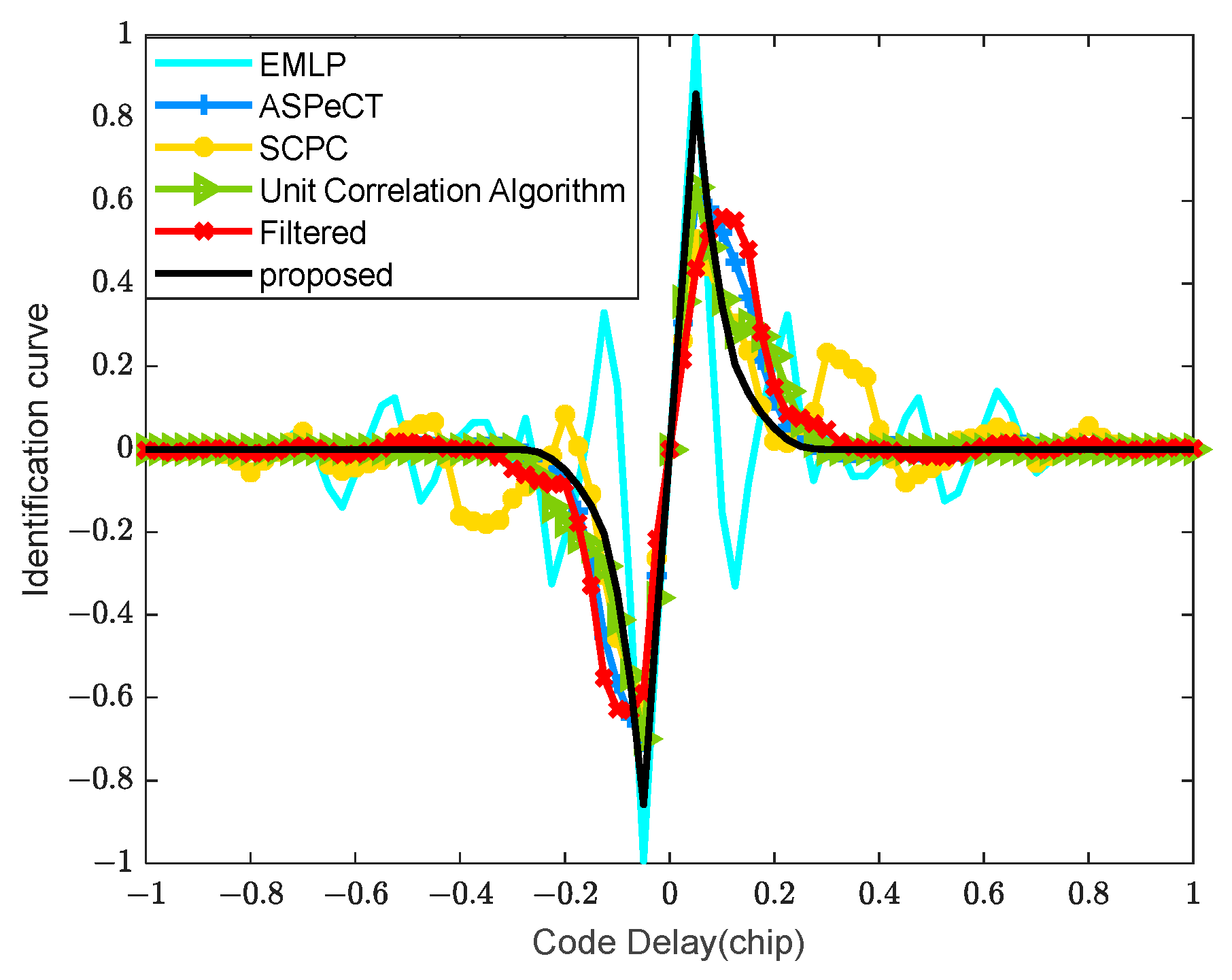
3.4. Phase Identification Curve
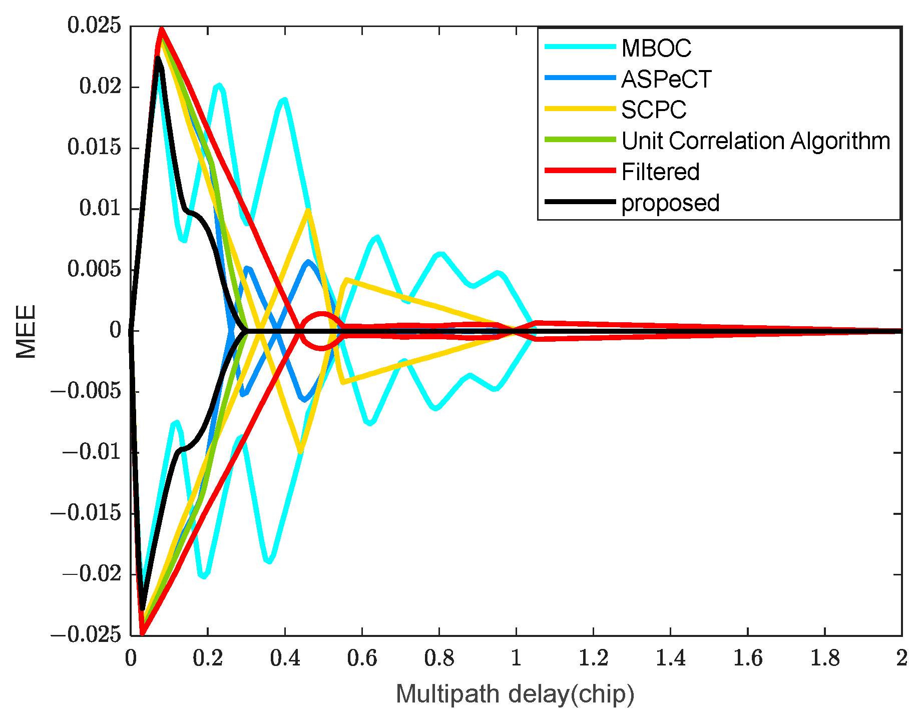
To evaluate the tracking performance of each method, the EMLP discriminator is used in this paper for analysis [18], and (35) is the phase discrimination formula for the algorithms in this paper. Because of the presence of subcarriers, the tracking loop uses a narrow correlation technique, so the simulation sets the front-end bandwidth to be infinite and the correlator interval to be 0.05 Tc, and Figure 8 illustrates the phase identification curves of five algorithms for MBOC signals. The simulation results show that the SCPC and Filtered correlation algorithm can eliminate most of the mis-locking points, and this paper’s algorithm, the ASPeCT and unit correlation algorithm can eliminate all the mis-locking points. Compared with ASPeCT, SCPC, Unit Correlation algorithm, and Filtered correlation algorithm, the slope gain of this paper’s algorithm is increased by 2.7 dB, 4.6 dB, 2.7 dB, and 5.9 dB, respectively. The advantage of this paper’s algorithm over other algorithms is that this paper’s algorithm eliminates all the mis-locking points while maintaining a high phase identification gain.

3.5. Anti-Multipath

The multipath effect will change the location of the point where the discriminant curve crosses the zero point, resulting in distortion of the correlation function, which in turn triggers the tracking error, so the ability to resist multipath is one of the important indexes to evaluate the performance of the tracking algorithms, among which the Multipath Error Envelope (MEE) is the key index to evaluate the ability of the tracking loop to resist multipath interference [29,30].
Assuming the presence of one multipath signal influence and setting correlator interval to 0.1 T c , Figure 9 shows the comparison of MEE curves using different algorithms. From Figure 9, it can be seen that the envelope extreme value, envelope interval length, and envelope area obtained using this paper’s algorithm are the smallest and, the smaller the three indicators are, the better resistance to multipath interference [11,31], so this paper’s algorithm is effective for anti-multipath interference.

3.6. Complexity Analysis

The N-point FFT operation can be decomposed into A complex addition and B complex multiplication, one complex multiplication can be decomposed into four real multiplications and two real additions, and one complex addition can be decomposed into two real additions [15,16,24].
According to [15], both the ASPeCT algorithm and the SCPC algorithm require eight FFT operations, four complex multiplications and two real multiplications, the Unit Correlation Algorithm requires five FFT operations, two complex multiplications and two real multiplications, the Filtered Correlation Algorithm requires five FFT operations, three complex multiplications and three real multiplications, and the proposed algorithm in this paper requires seven FFT operations, three complex multiplications and four real multiplications. The detailed comparison of computational complexity is shown in Table 2, from which it can be seen that the algorithm of this paper is slightly more computationally intensive compared to the Unit Correlation Algorithm and the Filtered Correlation Algorithm, but smaller than the ASPeCT and SCPC algorithms, which is within the acceptable range.

4. Conclusions

The algorithm in this paper generates three local signals, pseudo-random code, sinusoidal BOC(1,1) signal, and MBOC signal, which are correlated with the received signals and, by analyzing the characteristics of the three correlation functions, the reconstruction rules are designed, which ultimately achieve the elimination of side peaks and unambiguous synchronization. Theoretical and simulation results show that, in the tracking part, this paper’s algorithm eliminates all the mis-locked points, and its phase identification gain is more than 2 dB higher than that of other synchronization algorithms, and this paper’s algorithm has superior anti-multipath performance compared with other synchronization algorithms. In terms of detection probability, this paper’s algorithm is roughly the same as the ASPeCT algorithm, which is the direction of future improvement of this paper’s algorithm, and the acquisition performance of this paper’s algorithm will be further improved in subsequent work. As can be seen from Section 3.6, there is still room for improvement in the computational complexity part of the synchronization algorithm proposed in this paper, and the next work will optimize the synchronization algorithm for this aspect and simplify the algorithm to further reduce the complexity of the synchronization algorithm. Meanwhile, in the next work, we plan to implement the synchronization algorithm with the existing GNSS receiver hardware platform, observe the effect of the synchronization algorithm in the actual processing of satellite signals, and further improve the synchronization algorithm for the actual effect.

Author Contributions

Conceptualization, Y.J. and T.W.; methodology, Y.J.; validation, Y.J., T.W. and X.S.; investigation, Y.J. and X.S.; data curation, Y.J. and X.S.; writing—original draft preparation, Y.J. and T.W.; writing—review and editing, Y.J., T.W. and X.S. All authors have read and agreed to the published version of the manuscript.

Funding

This research was funded by the National Natural Science Foundation of China, grant number 62061010 and 62161007; Guangxi Science and Technology Department Project, grant number AA23062038, AD22080061, AB23026120, ZY22096026.

Data Availability Statement

Data are contained within the article.

Conflicts of Interest

Author X.S. was employed by the GUET-Nanning E-Tech Research Institute Co., Ltd. The remaining authors declare that the research was conducted in the absence of any commercial or financial relationships that could be construed as a potential conflict of interest.

References

  1. Avila-Rodriguez, J.-A.; Hein, G.W.; Wallner, S.; Issler, J.-L.; Ries, L.; Lestarquit, L.; Latour, A.D.; Godet, J.; Bastide, F.; Pratt, T.; et al. The MBOC Modulation: The Final Touch to the Galileo Frequency and Signal Plan. Navigation 2008, 55, 15–28. [Google Scholar] [CrossRef]
  2. Yang, Z.; Huang, Z.; Geng, S. Codes Cross-Correlation Analysis and Data/Pilot Code Pairs Optimization for Galileo E1 OS and GPS L1C. Chin. J. Aeronaut. 2013, 26, 751–765. [Google Scholar] [CrossRef]
  3. Zitouni, S.; Rouabah, K.; Chikouche, D.; Mokrani, K.; Atia, S.; Harba, R.; Ravier, P. General Analytical Models Characterizing MBOC Modulated Signal. Aerosp. Sci. Technol. 2016, 50, 112–126. [Google Scholar] [CrossRef]
  4. Upadhyay, D.J.; Bhadouria, V.S.; Majithiya, P.J.; Bera, S.C. Synthesized Binary Offset Carrier Modulation for Interoperable GNSS L1 Band Signals. NAVIGATION J. Inst. Navig. 2024, 2, 71. [Google Scholar] [CrossRef]
  5. Zitouni, S.; Chikouche, D.; Rouabah, K. Common GPS/Galileo Signals: MBOC VS BOC(1,1) Performance Comparison. In Proceedings of the 2013 8th International Workshop on Systems, Signal Processing and Their Applications (WoSSPA), Algiers, Algeria, 12–15 May 2013; pp. 510–514. [Google Scholar]
  6. Zhao, X.; Huang, X.; Liu, Z.; Xiao, Z.; Sun, G. Improved MBOC Modulations Based on Periodic Offset Subcarrier. IET Commun. 2021, 15, 1831–1848. [Google Scholar] [CrossRef]
  7. Fishman, P.M.; Betz, J.W. Predicting performance of direct acquisition for the M-code signal. In Proceedings of the 2000 National Technical Meeting of the Institute of Navigation, Anaheim, CA, USA, 26–28 January 2000; pp. 574–582. [Google Scholar]
  8. Martin, N.; Leblond, V.; Guillotel, G.; Heiries, V. BOC(x,y) Signal Acquisition Techniques and Performances. In Proceedings of the 16th International Technical Meeting of the Satellite Division of The Institute of Navigation, Portland, OR, USA, 9–12 September 2003; pp. 188–198. [Google Scholar]
  9. Yang, L.; Pan, C.; Feng, Y.; Bo, Y. The Research of Side-Band Acquisition for BOC-Modulated Signal. In Proceedings of the 2007 International Conference on Wireless Communications, Networking and Mobile Computing, Shanghai, China, 21–25 September 2007; pp. 645–648. [Google Scholar]
  10. Fu, Q.; Wang, H.; Ji, Y.; Shi, H. Research Development of Unambiguous Acquisition Method of BOC Signal. Mod. Def. Techonl. 2013, 41, 91–96+106. [Google Scholar]
  11. Fu, Q.; Chen, X.; Ji, Y.; Sun, X.; Wei, B. An Unambiguous Tracking Method Based on Combination of Sub Cross-Correlation Functions for BOC Signals. Trans. Beijing Inst. Technol. 2020, 40, 1207–1215. [Google Scholar]
  12. Longji, Z.; Ju, W. Ambiguity Mitigating Tracking Method for BOC(1,1) and MBOC(6,1,1/11) Signals. In Proceedings of the 2017 First International Conference on Electronics Instrumentation & Information Systems (EIIS), Harbin, China, 3–5 June 2017; pp. 1–4. [Google Scholar]
  13. Chae, K.; Lee, S.R.; Liu, H.; Yoo, S.; Kim, S.Y.; Jee, G.-I.; Yeom, D.-J.; Yoon, S. A Novel Unambiguous Composite Binary Offset Carrier(6,1,1/11) Tracking Based on Partial Correlations. Comput. Electr. Eng. 2016, 50, 54–66. [Google Scholar] [CrossRef]
  14. Chae, K.; Yoo, S.; Kim, S.Y.; Jee, G.-I.; Yeom, D.-J.; Yoon, S. Unambiguous Tracking Technique Based on Sub-Carrier Pulse Grouping for TMBOC-Modulated Signals in GPS. IEEE Access 2016, 4, 7785–7794. [Google Scholar] [CrossRef]
  15. Sun, X.; Song, S.; JI, Y.; Liang, W.; LI, Y. Novel Unambiguous Tracking Algorithm for BOC and Its Derivative Signals. J. Xidian Univ. 2022, 49, 58–66. [Google Scholar]
  16. Ji, Y.; Zhang, Y.; Sun, X.; Jia, X.; Li, J. Enhanced Synchronization Algorithms for BOC Signals Based on Reconstructed Sub-Correlation Functions. Electronics 2023, 12, 2839. [Google Scholar] [CrossRef]
  17. Yoon, S.; Chae, K.; Kim, S.Y. A New Approach to Local Signal Design for Enhanced TMBOC Signal Tracking. J. Electr. Eng. Technol. 2020, 15, 1837–1845. [Google Scholar] [CrossRef]
  18. Wang, P.; Hua, R.; Jin, Z. A Combined Sub-Carrier Unambiguous Tracking Algorithm of B1C Signals. J. Chin. Inert. Technol. 2023, 31, 569–577. [Google Scholar]
  19. Xu, R.; Tang, R.; Luo, K.; Zeng, Q.; Liu, J. Fast and High Accurate Acquisition Algorithm of BeiDou B1C Signal Based on ASPeCT. J. Chin. Inert. Technol. 2021, 29, 62–68. [Google Scholar]
  20. Zhang, T.; Yan, Z.; Ou, X.; Qian, W. Acquisition Algorithm Combining Parallel Code Phase with Fractal Reconstruction of TMBOC Modulation Signal. J. Shanghai Jiaotong Univ. 2016, 50, 782–787. [Google Scholar]
  21. Ji, Y.; Song, S.; Sun, X.; Guo, N.; Li, Y. A Novel Unambiguous Acquisition Algorithm Based on Segmentation Reconstruction for BOC(n,n) Signal. IEICE Trans. Commun. 2023, 106, 287–295. [Google Scholar] [CrossRef]
  22. Julien, O.; Macabiau, C.; Cannon, M.; Lachapelle, G. ASPeCT: Unambiguous Sine-BOC(n,n) Acquisition/Tracking Technique for Navigation Applications. IEEE Trans. Aerosp. Electron. Syst. 2007, 43, 150–162. [Google Scholar] [CrossRef]
  23. Heiries, V.; Roviras, D.; Ries, L.; Calmettes, V. Analysis of Non Ambiguous BOC Signal Acquisition Performance. In Proceedings of the 17th International Technical Meeting of the Satellite Division of the Institute of Navigation, Long Beach, CA, USA, 21–24 September 2004; pp. 2611–2622. [Google Scholar]
  24. Ji, Y.; Liu, Y.; Zhen, W.; Sun, X.; Yu, B. An Unambiguous Acquisition Algorithm Based on Unit Correlation for BOC(n,n) Signal. IEICE Trans. Commun. 2017, 100, 1507–1513. [Google Scholar] [CrossRef]
  25. Avellone, G.; Frazzetto, M.; Messina, E. On the Acquisition Ambiguity for Galileo BOC(n,n) Modulated Signals. In Proceedings of the 2007 IEEE International Conference on Communications, Glasgow, UK, 24–28 June 2007; pp. 4438–4443. [Google Scholar]
  26. Li, M.; Hu, H.; Guo, M.; Yu, F.; Xie, H. Unambiguous acquisition algorithm based on cross-correlation function shift multiplication for BOC (m,n) signals. Acta Aeronaut. Astronaut. Sin. 2022, 43, 621–632. [Google Scholar]
  27. Zhen, M.; Changdi, L.; Feng, S. Unambiguous Acquisition Method for Satellite Navigation BOC Modulated Signals Based on the Design of Shape Code Vector. J. Syst. Sci. Math. Sci. 2024, 1–16. [Google Scholar]
  28. Sun, X.; Song, S.; Ji, Y.; Gan, X.; Yan, S.; Jia, X. An Unambiguous Synchronization Scheme for GNSS BOC Signals Based on Reconstructed Correlation Function. Sensors 2021, 21, 1982. [Google Scholar] [CrossRef]
  29. Hu, M.; Wu, D. Evaluation of Anti-Multipath Performance to Satellite Navigation Signal Tracking on L1/E1/B1 Frequency Band. J. Syst. Simul. 2016, 28, 106–113. [Google Scholar]
  30. Deng, Z.; Hu, E.; Yin, L.; Liu, W.; Yang, L.; Arain, Q.A. An Unambiguous Tracking Technique for Sine-BOC(Kn,n) Modulated GNSS Signals. Wirel. Pers. Commun. 2018, 103, 1101–1112. [Google Scholar] [CrossRef]
  31. Liu, H.; Cheng, X.; NI, S.; Wang, F. Evaluation of Multipath Mitigation Performances Based on Error Envelope. J. Natl. Univ. Def. Technol. 2011, 33, 72–75. [Google Scholar]
Figure 1. Autocorrelation function.
Electronics 13 03375 g001
Figure 2. Reconstruction process of MBOC signal by this paper’s algorithm. (a) Correlation functions R M B O C / B O C , R M B O C / P R N , and R M B O C ; (b) correlation functions R 1 , R 2 and R 3 ; (c) correlation functions R 4 and R n e w .
Electronics 13 03375 g002
Figure 3. Block diagram of acquisition.
Electronics 13 03375 g003
Figure 4. Block diagram of tracking loop.
Electronics 13 03375 g004
Figure 5. Comparison of normalized correlation peaks.
Electronics 13 03375 g005
Figure 6. Comparison of detection probability.
Electronics 13 03375 g006
Figure 7. Comparison of peak-to-average ratios.
Electronics 13 03375 g007
Figure 8. Comparison of identification curves.
Electronics 13 03375 g008
Figure 9. Comparison of the MEE.
Electronics 13 03375 g009
Table 1. Experimental configuration parameters.
Parameter TypeParametricParameter TypeParametric
Experimental ObjectMBOC(6,1,1/11)Code Phase Shift600
Sampling frequency ( f s )40.92 MHzFrequency search range[−10 KHz, 10 KHz]
Intermediate frequency ( f I F )30 MHzFrequency search step500 Hz
Doppler frequency ( f d )2500 HzSNR[−40 dB, −20 dB]
Table 2. Comparison of computational complexity.
AlgorithmsReal MultiplicationsReal Addition
ASPeCT/SCPC 16 N log 2 N + 18 N 24 N log 2 N + 8 N
Unit Correlation Algorithm 10 N log 2 N + 10 N 7 N log 2 N + 7 N
Filtered Correlation Algorithm 10 N log 2 N + 12 N 15 N log 2 N + 12 N
proposed 14 N log 2 N + 13 N 21 N log 2 N + 14 N
Disclaimer/Publisher’s Note: The statements, opinions and data contained in all publications are solely those of the individual author(s) and contributor(s) and not of MDPI and/or the editor(s). MDPI and/or the editor(s) disclaim responsibility for any injury to people or property resulting from any ideas, methods, instructions or products referred to in the content.

