

Grid-Based DBSCAN Clustering Accelerator for LiDAR’s Point Cloud
 ,
,  , , ,
, , ,  , and
, and
Abstract
:1. Introduction
- The DBSCAN algorithm with grid for solid state LiDAR effectively saved computational burden.
- The DBSCAN accelerator significantly decreases computation time of clustering.
- The feasibility of the DBSCAN accelerator in autonomous robots was confirmed by connecting it to a low-power core, demonstrating effective object detection with low power consumption.
2. Related Work
2.1. DBSCAN LiDAR Clustering
2.2. DBSCAN Clustering Accelerator
2.3. Low-Power Object Detection
2.4. Object Detection for Autonomous Driving with Various Sensors
3. Architecture
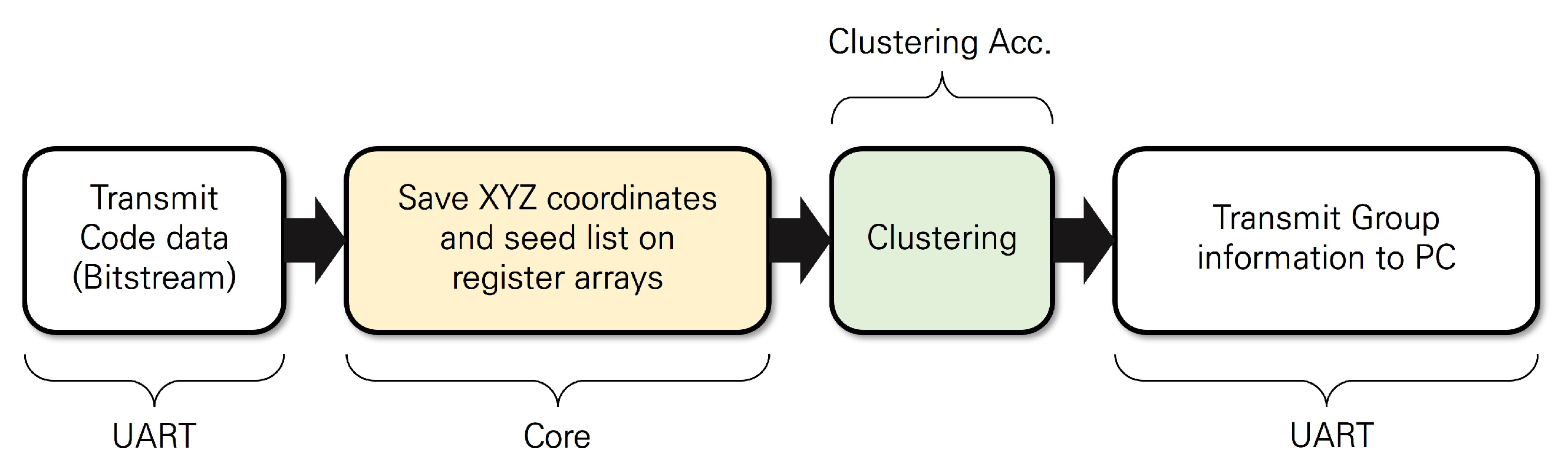
3.1. DBSCAN Clustering System with a Low-Power Core
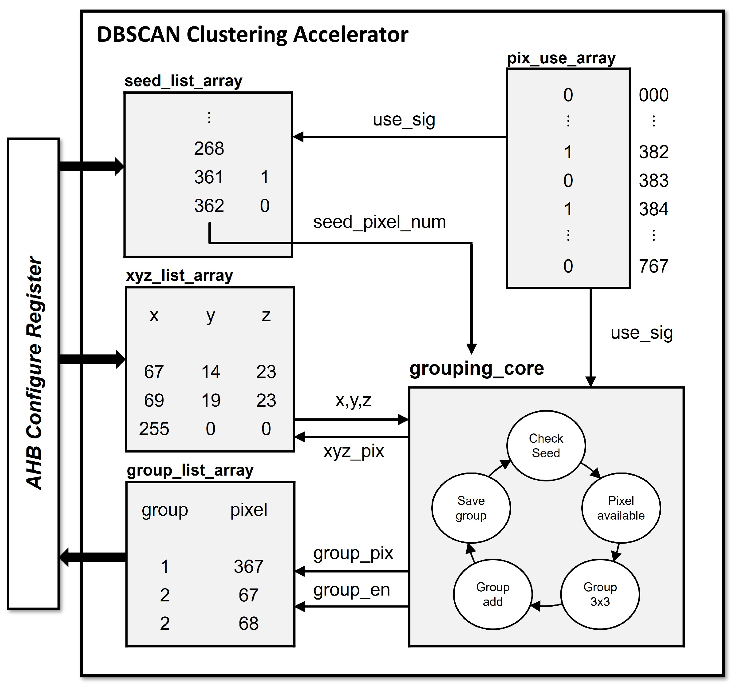
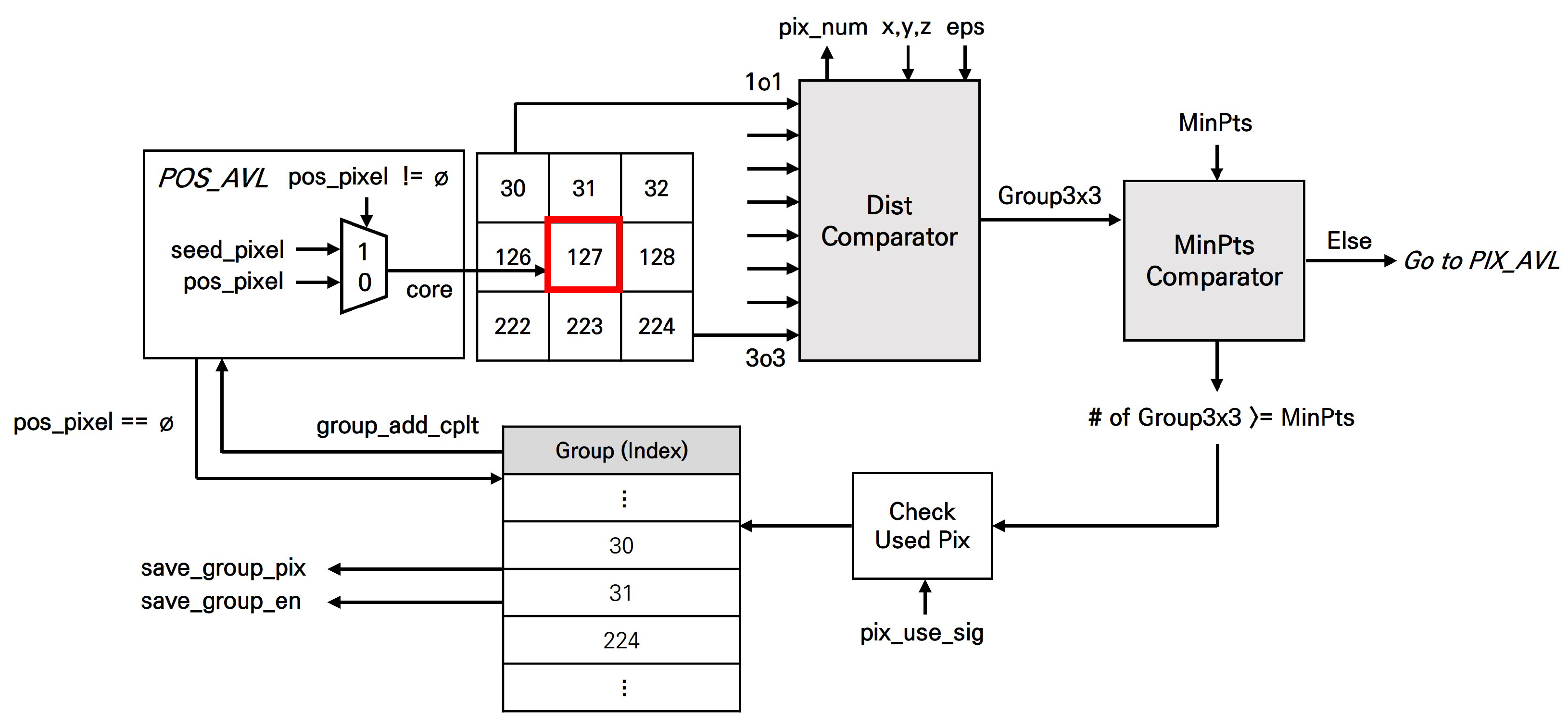
3.2. DBSCAN Clustering Accelerator
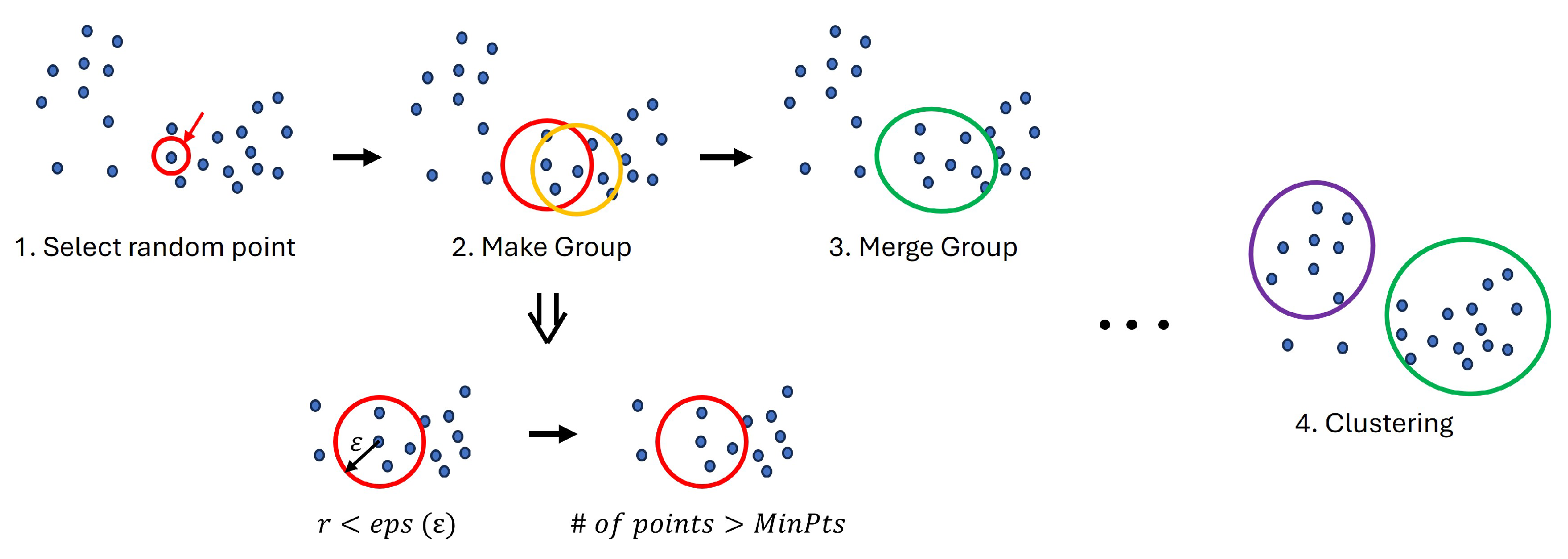
3.2.1. Proposed DBSCAN Algorithm
| Algorithm 1 Proposed grid-based DBSCAN algorithm |
Require:
|
| Algorithm 2 Clustering(c, , ) |
Require:
|
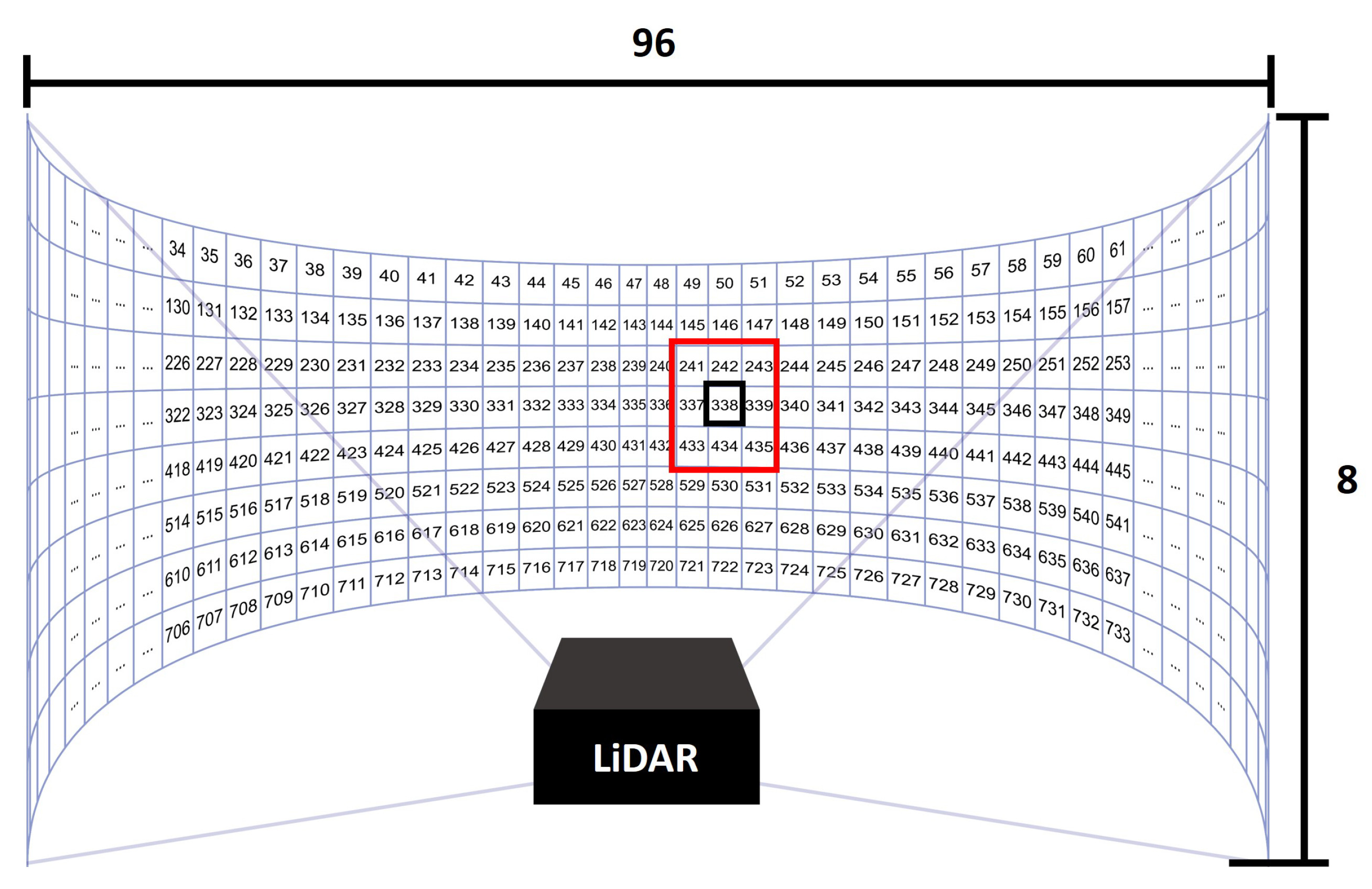
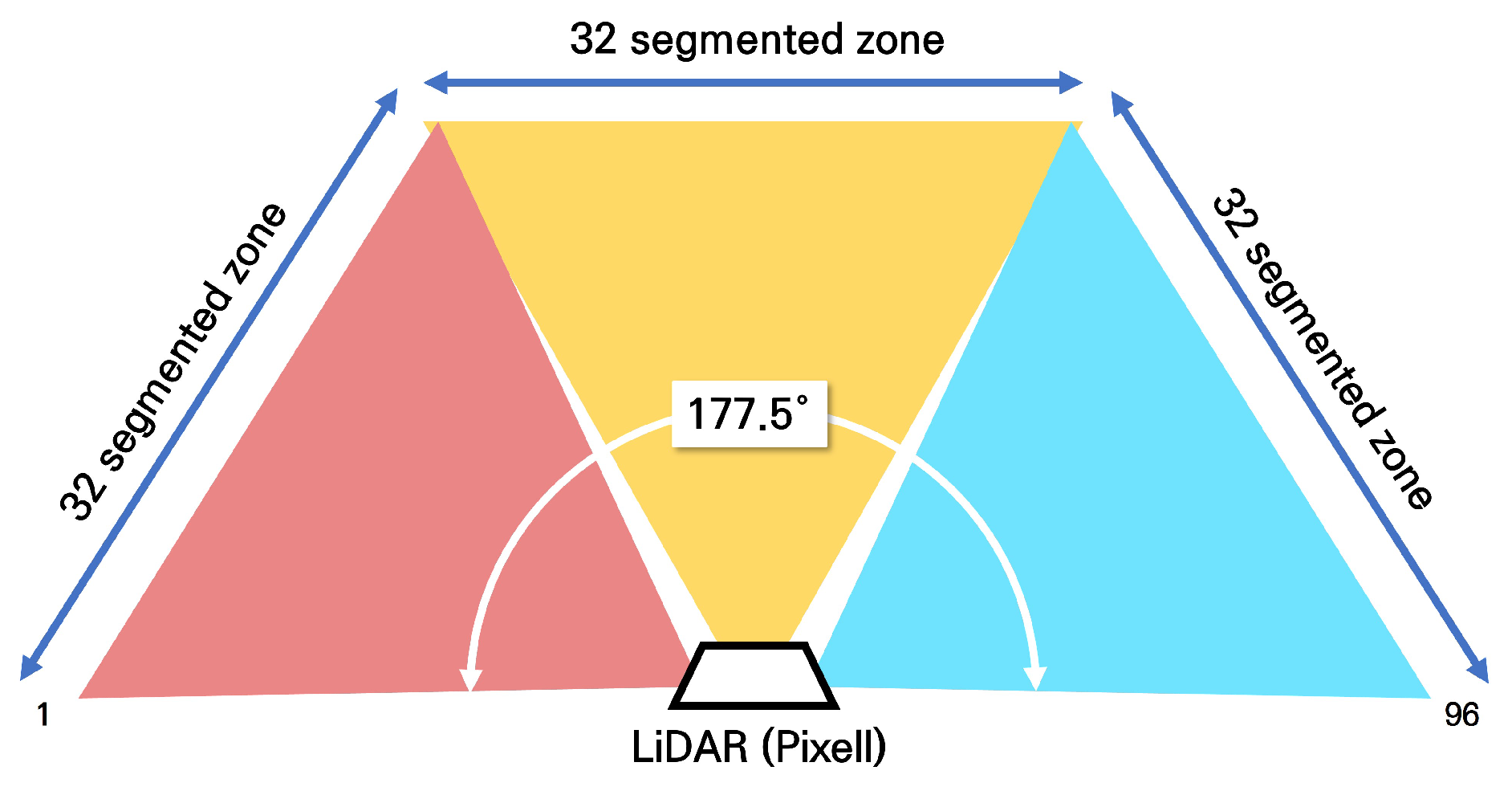
3.2.2. Architecture
4. Implementation and Analysis
4.1. Environment Setup
4.2. Experiments
5. Conclusions
Author Contributions
Funding
Data Availability Statement
Conflicts of Interest
References
- Sharma, T.; Debaque, B.; Duclos, N.; Chehri, A.; Kinder, B.; Fortier, P. Deep Learning-Based Object Detection and Scene Perception under Bad Weather Conditions. Electronics 2022, 11, 563. [Google Scholar] [CrossRef]
- Liu, S.; Liu, L.; Tang, J.; Yu, B.; Wang, Y.; Shi, W. Edge computing for autonomous driving: Opportunities and challenges. Proc. IEEE 2019, 107, 1697–1716. [Google Scholar] [CrossRef]
- Yurtsever, E.; Lambert, J.; Carballo, A.; Takeda, K. A Survey of Autonomous Driving: Common Practices and Emerging Technologies. IEEE Access 2020, 8, 58443–58469. [Google Scholar] [CrossRef]
- Shin, J.Y.; Ho Lee, S.; Go, K.; Kim, S.; Lee, S.E. AI Processor based Data Correction for Enhancing Accuracy of Ultrasonic Sensor. In Proceedings of the 2023 IEEE 5th International Conference on Artificial Intelligence Circuits and Systems (AICAS), Hangzhou, China, 11–13 June 2023; pp. 1–4. [Google Scholar] [CrossRef]
- Jeong, Y.; Jeong, W.S.; Shin, J.Y.; Lee, S.E. The Design of Embedded Fuzzy Logic Controller for Autonomous Mobile Robots. In Proceedings of the 2023 20th International SoC Design Conference (ISOCC), Jeju, Republic of Korea, 25–28 October 2023; pp. 145–146. [Google Scholar] [CrossRef]
- Jeong, Y.W.; Go, K.H.; Lee, S.E. Robot-on-Chip: Computing on a Single Chip for an Autonomous Robot. In Proceedings of the 2022 IEEE International Conference on Consumer Electronics (ICCE), Las Vegas, NV, USA, 7–9 January 2022; pp. 1–3. [Google Scholar] [CrossRef]
- Shnaps, I.; Rimon, E. Online Coverage of Planar Environments by a Battery Powered Autonomous Mobile Robot. IEEE Trans. Autom. Sci. Eng. 2016, 13, 425–436. [Google Scholar] [CrossRef]
- Zou, B.; Xu, X.; De Koster, R. Evaluating battery charging and swapping strategies in a robotic mobile fulfillment system. Eur. J. Oper. Res. 2018, 267, 733–753. [Google Scholar] [CrossRef]
- Jiang, P.; Ergu, D.; Liu, F.; Cai, Y.; Ma, B. A Review of Yolo Algorithm Developments. Procedia Comput. Sci. 2022, 199, 1066–1073. [Google Scholar] [CrossRef]
- He, K.; Gkioxari, G.; Dollar, P.; Girshick, R. Mask R-CNN. In Proceedings of the IEEE International Conference on Computer Vision (ICCV), Venice, Italy, 22–29 October 2017. [Google Scholar]
- Park, J.; Shin, J.; Kim, R.; An, S.; Lee, S.; Kim, J.; Oh, J.; Jeong, Y.; Kim, S.; Jeong, Y.R.; et al. Accelerating Strawberry Ripeness Classification Using a Convolution-Based Feature Extractor along with an Edge AI Processor. Electronics 2024, 13, 344. [Google Scholar] [CrossRef]
- Kim, S.; Park, J.; Jeong, Y.; Lee, S.E. Intelligent Monitoring System with Privacy Preservation Based on Edge AI. Micromachines 2023, 14, 1749. [Google Scholar] [CrossRef]
- Mao, J.; Shi, S.; Wang, X.; Li, H. 3D object detection for autonomous driving: A comprehensive survey. Int. J. Comput. Vis. 2023, 131, 1909–1963. [Google Scholar] [CrossRef]
- Wei, Z.; Zhang, F.; Chang, S.; Liu, Y.; Wu, H.; Feng, Z. MmWave Radar and Vision Fusion for Object Detection in Autonomous Driving: A Review. Sensors 2022, 22, 2542. [Google Scholar] [CrossRef]
- Nabati, R.; Qi, H. RRPN: Radar Region Proposal Network for Object Detection in Autonomous Vehicles. In Proceedings of the 2019 IEEE International Conference on Image Processing (ICIP), Taipei, Taiwan, 22–25 September 2019; pp. 3093–3097. [Google Scholar] [CrossRef]
- Wang, Y.; Jiang, Z.; Li, Y.; Hwang, J.N.; Xing, G.; Liu, H. RODNet: A Real-Time Radar Object Detection Network Cross-Supervised by Camera-Radar Fused Object 3D Localization. IEEE J. Sel. Top. Signal Process. 2021, 15, 954–967. [Google Scholar] [CrossRef]
- Pang, S.; Morris, D.; Radha, H. CLOCs: Camera-LiDAR Object Candidates Fusion for 3D Object Detection. In Proceedings of the 2020 IEEE/RSJ International Conference on Intelligent Robots and Systems (IROS), Las Vegas, NV, USA, 24 October 2020–24 January 2021; pp. 10386–10393. [Google Scholar] [CrossRef]
- Liang, Z.; Huang, Y. Survey on deep learning-based 3D object detection in autonomous driving. Trans. Inst. Meas. Control 2023, 45, 761–776. [Google Scholar] [CrossRef]
- Jin, X.; Yang, H.; He, X.; Liu, G.; Yan, Z.; Wang, Q. Robust LiDAR-based vehicle detection for on-road autonomous driving. Remote Sens. 2023, 15, 3160. [Google Scholar] [CrossRef]
- Adnan, M.; Slavic, G.; Martin Gomez, D.; Marcenaro, L.; Regazzoni, C. Systematic and comprehensive review of clustering and multi-target tracking techniques for LiDAR point clouds in autonomous driving applications. Sensors 2023, 23, 6119. [Google Scholar] [CrossRef]
- Kodinariya, T.M.; Makwana, P.R. Review on determining number of Cluster in K-Means Clustering. Int. J. 2013, 1, 90–95. [Google Scholar]
- Nielsen, F.; Nielsen, F. Hierarchical clustering. Introduction to HPC with MPI for Data Science; Springer: Cham, Switzerland, 2016; pp. 195–211. [Google Scholar]
- Kriegel, H.P.; Kröger, P.; Sander, J.; Zimek, A. Density-based clustering. Wiley Interdiscip. Rev. Data Min. Knowl. Discov. 2011, 1, 231–240. [Google Scholar] [CrossRef]
- Bushra, A.A.; Yi, G. Comparative analysis review of pioneering DBSCAN and successive density-based clustering algorithms. IEEE Access 2021, 9, 87918–87935. [Google Scholar] [CrossRef]
- Ester, M.; Kriegel, H.P.; Sander, J.; Xu, X. A density-based algorithm for discovering clusters in large spatial databases with noise. In Proceedings of the KDD, Portland, OR, USA, 2–4 August 1996; Volume 96, pp. 226–231. [Google Scholar]
- Chehata, N.; David, N.; Bretar, F. LIDAR data classification using hierarchical K-means clustering. In ISPRS Congress Beijing 2008; Citeseer: University Park, PA, USA, 2008; Volume 37, pp. 325–330. [Google Scholar]
- Ghosh, S.; Lohani, B. Mining lidar data with spatial clustering algorithms. Int. J. Remote Sens. 2013, 34, 5119–5135. [Google Scholar] [CrossRef]
- Yabroudi, M.E.; Awedat, K.; Chabaan, R.C.; Abudayyeh, O.; Abdel-Qader, I. Adaptive DBSCAN LiDAR Point Cloud Clustering For Autonomous Driving Applications. In Proceedings of the 2022 IEEE International Conference on Electro Information Technology (eIT), Mankato, MN, USA, 19–21 May 2022; pp. 221–224. [Google Scholar] [CrossRef]
- Wang, C.; Ji, M.; Wang, J.; Wen, W.; Li, T.; Sun, Y. An Improved DBSCAN Method for LiDAR Data Segmentation with Automatic Eps Estimation. Sensors 2019, 19, 172. [Google Scholar] [CrossRef]
- Zhang, C.; Wang, S.; Yu, B.; Li, B.; Zhu, H. A Two-Stage Adaptive Clustering Approach for 3D Point Clouds. In Proceedings of the 2019 4th Asia-Pacific Conference on Intelligent Robot Systems (ACIRS), Nagoya, Japan, 13–15 July 2019; pp. 11–16. [Google Scholar]
- Wu, J.; Xu, H.; Zheng, J.; Zhao, J. Automatic Vehicle Detection with Roadside LiDAR Data Under Rainy and Snowy Conditions. IEEE Intell. Transp. Syst. Mag. 2021, 13, 197–209. [Google Scholar] [CrossRef]
- Cao, M.; Wang, J. Obstacle detection for autonomous driving vehicles with multi-lidar sensor fusion. J. Dyn. Syst. Meas. Control 2020, 142, 021007. [Google Scholar] [CrossRef]
- Nguyen, H.T.; Lee, E.H.; Bae, C.H.; Lee, S. Multiple Object Detection Based on Clustering and Deep Learning Methods. Sensors 2020, 20, 4424. [Google Scholar] [CrossRef]
- Verucchi, M.; Bartoli, L.; Bagni, F.; Gatti, F.; Burgio, P.; Bertogna, M. Real-Time clustering and LiDAR-camera fusion on embedded platforms for self-driving cars. In Proceedings of the 2020 Fourth IEEE International Conference on Robotic Computing (IRC), Taichung, Taiwan, 9–11 November 2020; pp. 398–405. [Google Scholar]
- Tamayo, W.C.; Chelbi, N.E.; Gingras, D.; Faulconnier, F. Improving Object Distance Estimation in Automated Driving Systems Using Camera Images, LiDAR Point Clouds and Hierarchical Clustering. In Proceedings of the 2021 IEEE Intelligent Vehicles Symposium Workshops (IV Workshops), Nagoya, Japan, 11–17 July 2021; pp. 299–305. [Google Scholar]
- Wong, K.; Wang, S.; Ren, M.; Liang, M.; Urtasun, R. Identifying unknown instances for autonomous driving. In Proceedings of the Conference on Robot Learning, Virtual, 16–18 November 2020; pp. 384–393. [Google Scholar]
- Gao, F.; Li, C.; Zhang, B. A dynamic clustering algorithm for lidar obstacle detection of autonomous driving system. IEEE Sens. J. 2021, 21, 25922–25930. [Google Scholar] [CrossRef]
- Patwary, M.M.A.; Palsetia, D.; Agrawal, A.; Liao, W.K.; Manne, F.; Choudhary, A. A new scalable parallel DBSCAN algorithm using the disjoint-set data structure. In Proceedings of the SC ’12: Proceedings of the International Conference on High Performance Computing, Networking, Storage and Analysis, Salt Lake City, UT, USA, 10–16 November 2012; pp. 1–11. [Google Scholar]
- Götz, M.; Bodenstein, C.; Riedel, M. HPDBSCAN: Highly parallel DBSCAN. In Proceedings of the Workshop on Machine Learning in High-Performance Computing Environments, Austin, TX, USA, 15–20 November 2015; pp. 1–10. [Google Scholar]
- Gunawan, A.; de Berg, M. A Faster Algorithm for DBSCAN. Master’s Thesis, Eindhoven University of Technology, Eindhoven, The Netherlands, 2013. [Google Scholar]
- Ohadi, N.; Kamandi, A.; Shabankhah, M.; Fatemi, S.M.; Hosseini, S.M.; Mahmoudi, A. Sw-dbscan: A grid-based dbscan algorithm for large datasets. In Proceedings of the 2020 6th International Conference on Web Research (ICWR), Tehran, Iran, 22–23 April 2020; pp. 139–145. [Google Scholar]
- Hrutka, B.; Siki, Z.; Takács, B. Voxel-based point cloud segmentation and building detection. Int. Arch. Photogramm. Remote Sens. Spat. Inf. Sci. 2022, 48, 209–215. [Google Scholar] [CrossRef]
- Wang, Y.; Gu, Y.; Shun, J. Theoretically-efficient and practical parallel DBSCAN. In Proceedings of the 2020 ACM SIGMOD International Conference on Management of Data, Portland, OR, USA, 14–19 June 2020; pp. 2555–2571. [Google Scholar]
- Mahesh Kumar, K.; Rama Mohan Reddy, A. A fast DBSCAN clustering algorithm by accelerating neighbor searching using Groups method. Pattern Recognit. 2016, 58, 39–48. [Google Scholar] [CrossRef]
- Chen, Y.; Zhou, L.; Bouguila, N.; Wang, C.; Chen, Y.; Du, J. BLOCK-DBSCAN: Fast clustering for large scale data. Pattern Recognit. 2021, 109, 107624. [Google Scholar] [CrossRef]
- Hanafi, N.; Saadatfar, H. A fast DBSCAN algorithm for big data based on efficient density calculation. Expert Syst. Appl. 2022, 203, 117501. [Google Scholar] [CrossRef]
- Ji, Z.; Wang, C.L. Accelerating DBSCAN algorithm with AI chips for large datasets. In Proceedings of the 50th International Conference on Parallel Processing, Lemont, IL, USA, 9–12 August 2021; pp. 1–11. [Google Scholar]
- Nagarajan, V.; Kulkarni, M. RT-DBSCAN: Accelerating DBSCAN using Ray Tracing Hardware. In Proceedings of the 2023 IEEE International Parallel and Distributed Processing Symposium (IPDPS), St. Petersburg, FL, USA, 15–19 May 2023; pp. 963–973. [Google Scholar]
- Shi, Q.Y.S.; Wang, Q. FPGA based accelerator for parallel DBSCAN algorithm. Comput. Model. New Technol. 2014, 18, 135–142. [Google Scholar]
- Scicluna, N.; Bouganis, C.S. ARC 2014: A multidimensional FPGA-based parallel DBSCAN architecture. ACM Trans. Reconfigurable Technol. Syst. (TRETS) 2015, 9, 1–15. [Google Scholar] [CrossRef]
- Xu, W.; Li, P.; Zou, X.; Zhong, N.; Pan, W.; Yan, L. Proposal and FPGA implementation of DBSCAN clustering nonlinear detector for MMW RoF system. In Proceedings of the 2022 IEEE International Topical Meeting on Microwave Photonics (MWP), Orlando, FL, USA, 3–7 October 2022; pp. 1–4. [Google Scholar]
- Gavin, B.; Deng, T.; Ball, E. Low Area and Low Power FPGA Implementation of a DBSCAN-Based RF Modulation Classifier. IEEE Open J. Comput. Soc. 2024, 5, 50–61. [Google Scholar] [CrossRef]
- Porcello, J.C. Density-Based Clustering for Knowledge Discovery of High-Dimensional Time Series Data using FPGAs. In Proceedings of the 2021 IEEE Aerospace Conference (50100), Big Sky, MT, USA, 6–13 March 2021; pp. 1–7. [Google Scholar]
- Lee, S.; An, S.; Kim, R.; Oh, J.; Lee, S.E. Point Cloud Clustering System with DBSCAN Algorithm for Low-Resolution LiDAR. In Proceedings of the 2024 IEEE International Conference on Consumer Electronics (ICCE), Las Vegas, NV, USA, 6–8 January 2024; pp. 1–2. [Google Scholar] [CrossRef]
- Jose, G.; Kumar, A.; Kruthiventi SS, S.; Saha, S.; Muralidhara, H. Real-time object detection on low power embedded platforms. In Proceedings of the IEEE/CVF International Conference on Computer Vision Workshops, Seoul, Republic of Korea, 27–28 October 2019. [Google Scholar]
- Yu, J.; Guo, K.; Hu, Y.; Ning, X.; Qiu, J.; Mao, H.; Yao, S.; Tang, T.; Li, B.; Wang, Y.; et al. Real-time object detection towards high power efficiency. In Proceedings of the 2018 Design, Automation & Test in Europe Conference & Exhibition (DATE), Dresden, Germany, 19–23 March 2018; pp. 704–708. [Google Scholar] [CrossRef]
- Lapegna, M.; Balzano, W.; Meyer, N.; Romano, D. Clustering Algorithms on Low-Power and High-Performance Devices for Edge Computing Environments. Sensors 2021, 21, 5395. [Google Scholar] [CrossRef]
- Rashed, H.; Mohamed, E.; Sistu, G.; Kumar, V.R.; Eising, C.; El-Sallab, A.; Yogamani, S. FisheyeYOLO: Object detection on fisheye cameras for autonomous driving. In Proceedings of the Machine Learning for Autonomous Driving NeurIPS 2020 Virtual Workshop, Virtual, 11 December 2020; Volume 11, p. 1. [Google Scholar]
- Yahiaoui, M.; Rashed, H.; Mariotti, L.; Sistu, G.; Clancy, I.; Yahiaoui, L.; Kumar, V.R.; Yogamani, S. Fisheyemodnet: Moving object detection on surround-view cameras for autonomous driving. arXiv 2019, arXiv:1908.11789. [Google Scholar]
- Song, Y.; Xie, Z.; Wang, X.; Zou, Y. MS-YOLO: Object detection based on YOLOv5 optimized fusion millimeter-wave radar and machine vision. IEEE Sens. J. 2022, 22, 15435–15447. [Google Scholar] [CrossRef]
- Huang, X.; Tsoi, J.K.P.; Patel, N. mmWave Radar Sensors Fusion for Indoor Object Detection and Tracking. Electronics 2022, 11, 2209. [Google Scholar] [CrossRef]
- Déziel, J.; Merriaux, P.; Tremblay, F.; Lessard, D.; Plourde, D.; Stanguennec, J.; Goulet, P.; Olivier, P. PixSet: An Opportunity for 3D Computer Vision to Go Beyond Point Clouds With a Full-Waveform LiDAR Dataset. In Proceedings of the 2021 IEEE International Intelligent Transportation Systems Conference (ITSC), Indianapolis, IN, USA, 19–22 September 2021; pp. 2987–2993. [Google Scholar] [CrossRef]


| Ref. | Algorithm | Time Complexity | Features |
|---|---|---|---|
| KM Kumar et al., 2016 [44] | G-DBSCAN | A novel graph-based index structure method that groups data to accelerate the neighbor search operations. | |
| Y Chen et al., 2021 [45] | BLOCK-DBSCAN | ) | Approximation algorithm for large-scale data, judging whether two Inner core blocks are density reachable. |
| Y Wang et al., 2020 [29] | Practical Parallel DBSCAN | ) | Grid-based DBSCAN for parallel processing, with tree structure enabling merge groups for a variety # of clusters |
| N Ohadi et al., 2020 [41] | SW-DBSCAN | ) | Grid-based DBSCAN and a sliding window approach to large datasets |
| N Hanafi et al., 2022 [46] | OP-DBSCAN | Using local samples and concept of operational dataset to find neighbors |
| LUTs | Registers | BRAMs | Logic Elements | |
|---|---|---|---|---|
| Max 10 | - | - | 1,677,321 | 49,760 |
| Acc. with Cortex-M0. | 24,806 | 16,170 | 296,996 (18%) | 30,533 (61%) |
| Only Acc. | 17,648 | 13,687 | 34,816 (2%) | 22,972 (45%) |
| Dataset (a) | Dataset (b) | Dataset (c) | Dataset (d) | Dataset (e) | |
|---|---|---|---|---|---|
| Time | day | day | night | day | day |
| Weather | clouds | clouds | clouds | clouds | rain |
| Location | downtown | suburban | boulevard | highway | boulevard |
| # of frames | 2929 | 290 | 275 | 190 | 122 |
| Platform | Dataset (a) | Dataset (b) | Dataset (c) | Dataset (d) | Dataset (e) | Average |
|---|---|---|---|---|---|---|
| Original DBSCAN, i7-12700 | 220.35 | 253.8 | 220.4 | 245.8 | 230.07 | 224.48 |
| Proposed algorithm, i7-12700 | 7.87 | 14.91 | 8.29 | 7.24 | 7.24 | 8.45 |
| Raspberry Pi 4 | 43.87 | 63.85 | 46.27 | 44.74 | 44.74 | 45.69 |
| Proposed Accelerator * | 0.89 | 0.88 | 0.89 | 0.87 | 0.9 | 0.886 |
| Dataset | Raw Picture | Original DBSCAN SW | Proposed Algorithm SW | Proposed Acc. |
|---|---|---|---|---|
| Dataset (a), frame 997 |  |  |  | 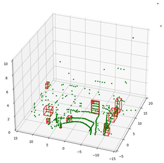 |
| Dataset (b), frame 24 | 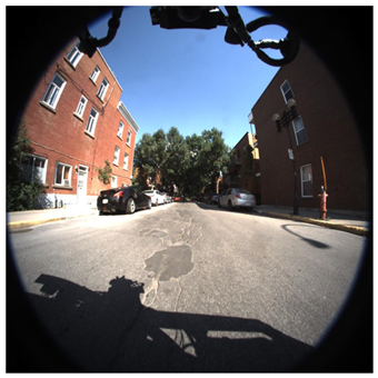 | 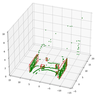 |  | 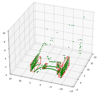 |
| Dataset (c), frame 166 |  | 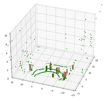 |  | 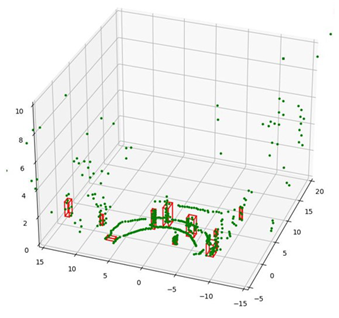 |
| Dataset (d), frame 41 | 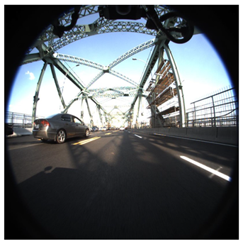 |  | 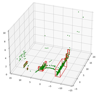 | 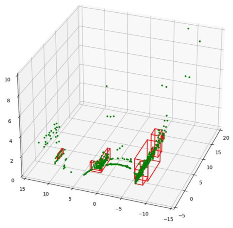 |
| Dataset (e), frame 37 | 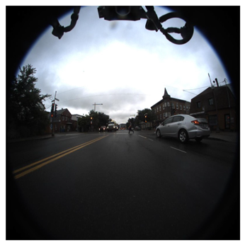 |  | 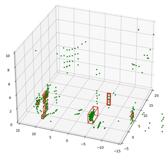 | 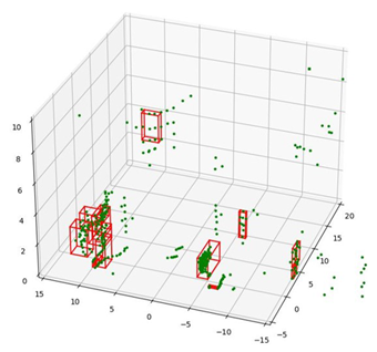 |
| Quantized, i7-12700 | Raspberry Pi 4 | FPGA | |
|---|---|---|---|
| TDP (W) | 65 | 2.7 | 1.035 |
| 0.54925 | 0.12336 | 0.00092 |
Disclaimer/Publisher’s Note: The statements, opinions and data contained in all publications are solely those of the individual author(s) and contributor(s) and not of MDPI and/or the editor(s). MDPI and/or the editor(s) disclaim responsibility for any injury to people or property resulting from any ideas, methods, instructions or products referred to in the content. |
© 2024 by the authors. Licensee MDPI, Basel, Switzerland. This article is an open access article distributed under the terms and conditions of the Creative Commons Attribution (CC BY) license (https://creativecommons.org/licenses/by/4.0/).
Share and Cite
Lee, S.; An, S.; Kim, J.; Namkung, H.; Park, J.; Kim, R.; Lee, S.E. Grid-Based DBSCAN Clustering Accelerator for LiDAR’s Point Cloud. Electronics 2024, 13, 3395. https://doi.org/10.3390/electronics13173395
Lee S, An S, Kim J, Namkung H, Park J, Kim R, Lee SE. Grid-Based DBSCAN Clustering Accelerator for LiDAR’s Point Cloud. Electronics. 2024; 13(17):3395. https://doi.org/10.3390/electronics13173395
Chicago/Turabian StyleLee, Sangho, Seongmo An, Jinyeol Kim, Hun Namkung, Joungmin Park, Raehyeong Kim, and Seung Eun Lee. 2024. "Grid-Based DBSCAN Clustering Accelerator for LiDAR’s Point Cloud" Electronics 13, no. 17: 3395. https://doi.org/10.3390/electronics13173395