Abstract
The integrated navigation system based on the Global Navigation Satellite System (GNSS) in conjunction with the strapdown inertial navigation system (SINS) and the Doppler Velocity Logger (DVL) is essential for accurate and long-distance navigation in maritime environments. However, the error of the integrated navigation system gradually diverges due to the inevitable velocity measurement error of DVL when GNSS outages occur. To ensure the high navigational accuracy and stability of SINS, it is necessary to dynamically adjust the damping state of SINS provided externally. In this paper, we have developed a novel method for damping state switching based on machine learning with SINS. We construct a model of the change in reference velocity error and use sliding window technology to obtain the reference velocity error for model training. Before training, the digital compass loop is designed to process and highlight the change in reference velocity change errors. In order to reduce the impact of the damping switching, a variable damping system is used to transform the traditional one-time switching of the damping coefficient into a gradual switching, effectively reducing the impact of a sudden change in the damping coefficient on the system. Simulation experiments and tests on ships show that the proposed method effectively reduces the overshoot error integrated underwater during state switching. This research is of great importance for the optimal design of integrated underwater navigation systems.
1. Introduction
A system based on a combination of GNSS/SINS/DVL is an instrument that can effectively provide navigation information and has been widely used in shipping in recent years. Compared to GNSS navigation with radio signals, SINS offers significantly improved autonomy, especially when the vehicle is operating in an underwater environment. As the medium of water can strongly absorb radio waves, the radio navigation system is difficult to apply to underwater vehicles [1,2]. The SINS plays an important role at this point. It primarily records the angular velocity and acceleration with the help of three orthogonal accelerometers and gyroscopes and obtains real-time information on the attitude, velocity, and position through integral operation. Although SINS has the advantages of strong autonomy and easy maintenance, it is also subject to the device itself. Among the failures of SINS are the drift errors of gyroscopes and accelerometers. The periodic oscillation errors that occur over time significantly limit and restrict the navigation accuracy of SINS, and error suppression needs to be solved urgently [3,4]. At present, SINS/DVL-integrated navigation and damping methods are usually used to suppress the periodic oscillation errors in underwater environments [5].
DVL is the instrument that can provide a relatively accurate speed in underwater environments and is therefore used to correct the errors of SINS. The integrated SINS/DVL navigation system is the common method to suppress SINS errors. However, the integrated SINS/DVL-integrated navigation system has strong nonlinearity and non-Gaussian noise, so the error model is difficult to build [6,7,8]. At the same time, the observability of the system is weak, and the filter can easily lead to the divergence of estimation errors in long-term navigation. The damping network is added to transform SINS into a stable system based on the control theory and thus to suppress the periodic oscillation errors. The classical damping network achieves the best effect by continuously monitoring the parameter debugging. This method is characterized by poor real-time performance and complex parameter calculation [9,10]. Even after the introduction of the damping network, the navigation errors in the mobile state will greatly be influenced by acceleration because the system structure has been changed. In order to compensate for the system errors caused by the vehicle in the traveling state, the system is normally set to the state of external horizontal damping in practical applications [11]. External horizontal damping is a method of suppressing vehicle maneuvering errors by introducing an external reference velocity, which is usually determined by DVL or Electromagnetic Velocity Log (EML) [12]. When the vehicle is in the external horizontal damping state, the accuracy of the system is affected by the external velocity errors. In actual navigation, vehicle maneuvering, turning, strong wind, and waves will cause velocity measurement errors. These types of velocity measurement errors are usually constant, gradual, and periodic. In general, the periodic error is much smaller than the other two errors [13]. In the actual system, there is usually an alternation between the external horizontal damping state and the undamped state. In [14], the influence of DVL velocity measurement errors on the system accuracy is analyzed. To reduce the influence of external velocity errors on the system, researchers have successfully improved the navigation accuracy from the aspects of the shape of the damping network and the information fusion method. In [15], the errors between the velocity of the DVL and the velocity of the SINS were analyzed and a hybrid adaptive control method was adopted to adjust the damping parameters to reduce the impact of external velocity errors. Refs. [16,17,18] use the reference velocity errors to estimate and compensate for the horizontal attitude angles according to the Kalman filter principle. The traditional control loop for external horizontal damping is modified, and the adjustment time is shortened by adding a forward loop [19]. In addition, there is a damping technology for error suppression based on phase modulation [20].
When the damping state is switched, an overshoot error inevitably occurs. Therefore, the variable damping method is adopted and used for suppression. A proportional element is added to the horizontal correction loop of the SINS to effectively suppress the overshoot error [21]. The strategy of adaptive adjustment of the damping parameters as a function of the vehicle acceleration is used to suppress the overshoot error [22]. According to the principle of a complementary filter, a new damping network is designed, which can effectively suppress the speed measurement errors of DVL [23]. The fuzzy neural network is used to adaptively adjust the damping parameters to suppress the overshoot error [24]. In [25], a new damping network based on the equivalence between the compass loop and the traditional damping network is proposed. A classical fuzzy controller is designed to control the switch for the damping state, and a complementary high-order filter is used to suppress the errors [26].
Although the current methods can reduce the influence of the reference velocity errors, they are not suitable when the reference velocity errors remain large over a long period of time. Therefore, state switching must be considered. Considering the overshoot error caused by the conventional state switching, the variable damping method is used in this paper to suppress the overshoot error. In order to avoid the sudden change in the damping coefficient, the variable damping method transforms it into a gradual situation of constant step switching. To reduce the influence of external velocity measurement errors on the SINS, a machine learning method combined with a slide window detector is proposed to learn the velocity measurement errors, so as to control and identify the damping state. In addition, in order to reduce the noise of the DVL, a digital compass loop is added to the SINS damping loop to reduce the noise of the external velocity and emphasize the change in the reference velocity errors. Finally, the proposed method is verified by simulation and ship data.
The specific structure of this paper is as follows. In the second section, the traditional principle of external horizontal damping is introduced, and in the third section, the damping switch control method using the machine learning method is described. In the fourth section, the numerical simulation is carried out. In the fifth section, the semi-physical simulation test is carried out using the real data. In the sixth section, the corresponding conclusions are presented.
2. External Horizontal Damping Network Design
2.1. Principle of External Horizontal Damping Network
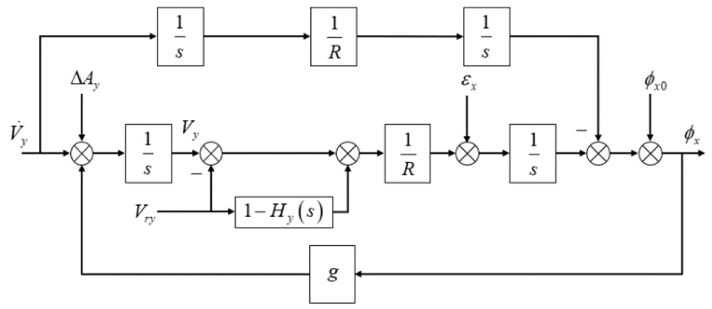
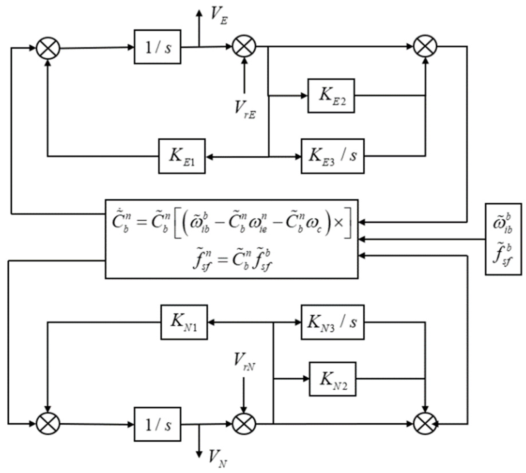
Taking the single channel east horizontal loop as shown in Figure 1 [6], the external horizontal damping network realizes the damping effect of the horizontal loop by comparing the external measured velocity with the inertial velocity. represents the north acceleration, represents the north accelerometer error, represents north velocity, represents the external reference north velocity, represents east gyroscope drift, represents the initial value of the pitch angle error, represents the pitch angle error, represents the gravitational acceleration, and represents the earth radius.

Figure 1.
Block diagram of east-level correction circuit.
The form of the transfer function to calculate the pitch angle error from the east velocity reference of the vehicle and its derivative is given by [26,27]
where is the external measurement velocity error; is the change rate of external velocity error. Equation (1) shows that the change in pitch angle error is independent of the ship platform acceleration and only depends on the external measurement velocity after introducing the external measurement velocity for compensation. Reasons why the east horizontal loop of the SINS corresponds to the design principle of the control system are explained in the next sentences. The SINS without a damping network is in a critical stable state. In order to effectively attenuate the oscillation errors, the damping network should be selected with corresponding phase advance correction in the middle frequency band with respect to Schuler’s frequency to ensure that all the characteristic roots of the SINS closed-loop characteristic equation with the damping network are in the left half plane of the s plane. In addition, the amplitude of the damping network is close to 1, and the damping ratio is also close to 0.5. In this case, the damping effect is the best.
2.2. Adaptive Parameter Design Principle of Damping Network
Although the introduction of reference velocity reduces the impact of a ship platform maneuver on SINS, it additionally introduces external measurement velocity error. According to the analysis of Equation (1), the external measurement velocity error will reduce the navigation accuracy. Therefore, it is very important to dynamically switch the damping state. It is necessary to seek a damping network with easy change in damping parameters and simple structure. In this paper, we use the following form of a second-order damping network.
According to the terminal value theorem, , we can obtain ; that is, . According to Equations (1) and (2), the closed-loop transfer function of the system can be described as follows:
The expressions of amplitude frequency characteristics and phase frequency characteristics of the second-order damping network are given as Equations (4) and (5).
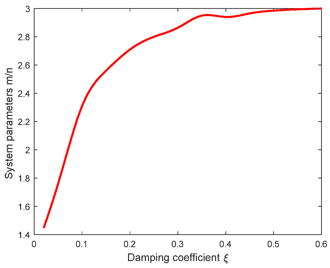
The damping network is introduced to ensure the stability of the closed-loop system. There must be a positive phase at , so there is , and holds. Because a, b, c, and d are all real numbers, there must be . From the amplitude frequency characteristic of the second-order system, in the place, reached the maximum value . So, when and remain stable, the relative resonance peak of the system shows a decreasing trend with . So, it can be satisfied by adjusting the value of to achieve variable design requirements of . According to the stability principle of a closed-loop system, the [28]. In order to realize the adaptive change in damping parameters, firstly, the damping parameter range is preset as , and the optimal value of corresponding to the relative resonant peak is obtained by using the Nichols chart of the closed-loop transfer function of the system. Finally, the cubic spline function is used to fit the relationship between the damping parameter and the system parameter value. The fitting sample is . The fitting curve is shown by Figure 2.
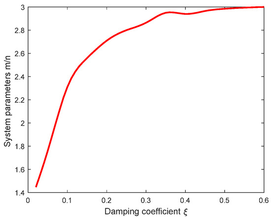
Figure 2.
Fitting curve of damping parameter and system parameter .
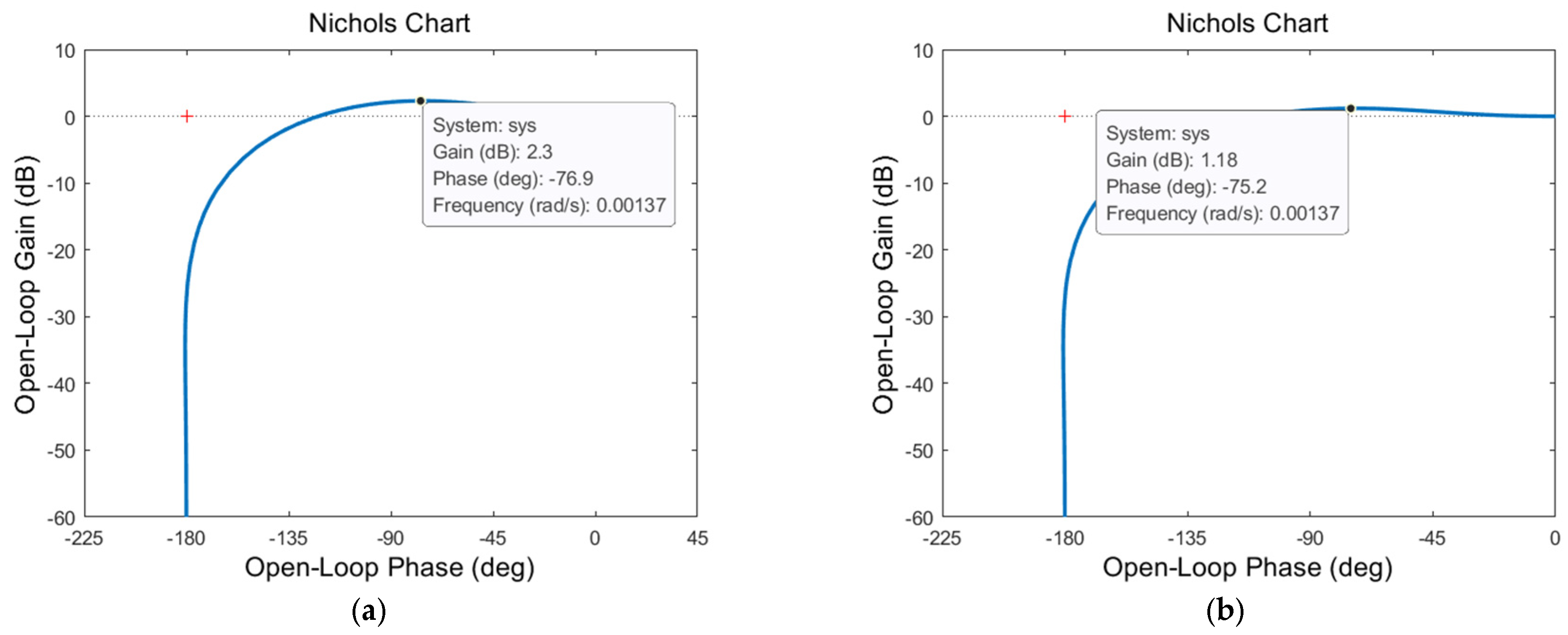
In order to verify the accuracy of the fitting between the system parameter and the damping parameter , two groups of damping parameters are randomly selected as , and the system parameters are 2.753 and 2.979, respectively. The Nichols diagram of the closed-loop transfer function is shown in Figure 3. Calculated relative resonance peak is consistent with the theoretical value obtained from the Nichols diagram, which indicates that the damped network used in this paper is correct.
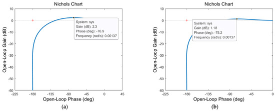
Figure 3.
The Nichols diagram of the closed-loop transfer function: (a) the Nichols chart of the level channel when ; (b) the Nichols chart of the level channel when .
2.3. Discrete Method of Damping Network
In practice, the damping network will not appear in the form of a frequency domain, so it must be discretized in the digital computer. At present, the discrete damping network methods mainly include the introduction of the intermediate variable method and bilinear transformation method [26]. In order to ensure single-value mapping and avoid frequency aliasing, the bilinear transformation method is adopted. The specific process of discrete processing using the bilinear transformation method is given by
In Equation (6), all parameters are given by
The values of a to d can be obtained by Equation (9).
3. Damping State Identification Method Based on Support Vector Machine
3.1. The Effect of Reference Velocity Errors on SINS
Reference external velocity error mainly refers to the error caused by external sensor DVL during measurement. When the ship or underwater vehicle accelerates linearly or turns or swings, it is bound to produce different forms of external velocity errors. In general, there are three types of velocity errors in external measurements: the step form, ramp form, and periodic form. The oscillation amplitude of periodic error is related to the frequency of velocity measurement error. In Equation (1), the initial external measurement velocity error is ignored, and only the change rate of external measurement velocity error is retained, given as
The above equation indicates that the change in the external measurement velocity error change rate will lead to the overshoot of pitch angle error. In the practical work of SINS, the overshoot caused by the external measurement velocity error is smaller than the inherent Schuler period of the system. In addition, we integrate the change rate of external measurement velocity error in a certain period of time to obtain the change in external measurement velocity error in a certain period of time.
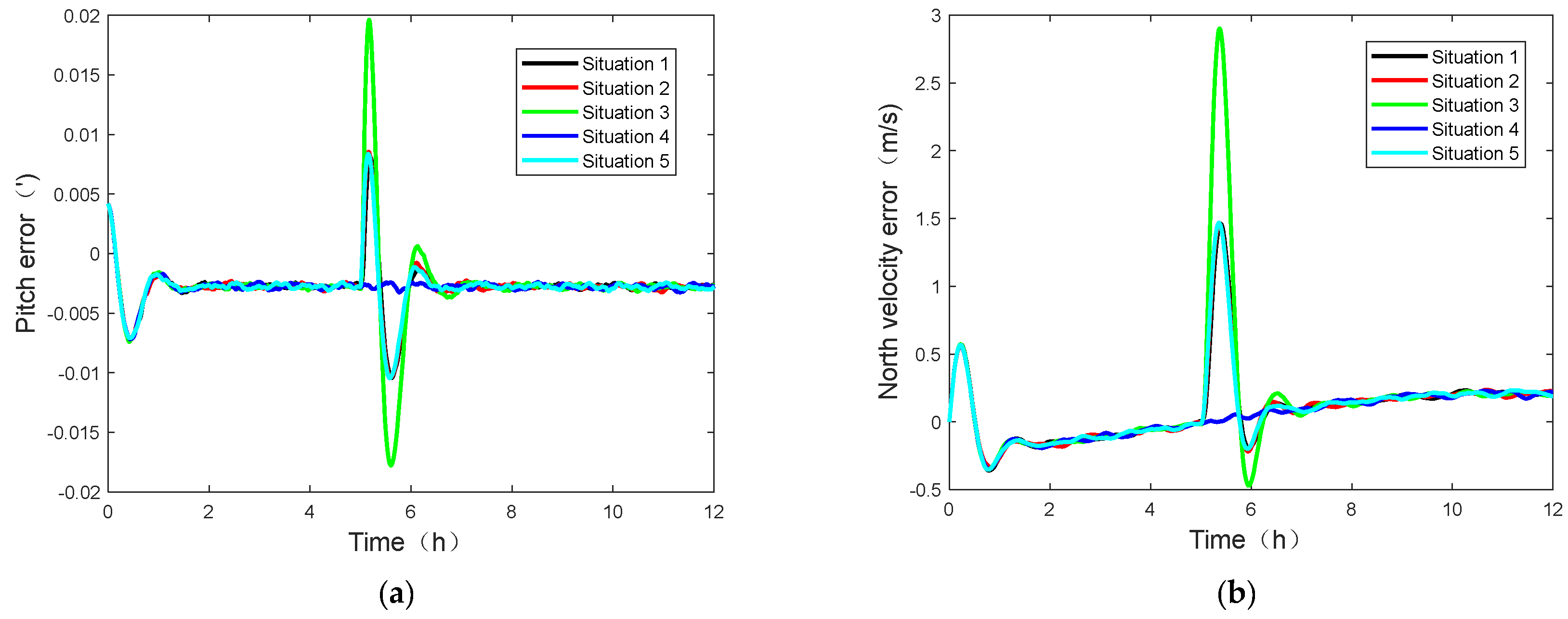
The above equation shows that the dynamic overshoot of the pitch angle error also depends on the integral value of the change rate of the external measured velocity error. It is generally understood that in a certain period of time, the same integral value of the reference velocity error change rate will bring the same dynamic overshoot error to the system. To verify this conclusion, the following simulation analysis is carried out. Firstly, the constant bias of an inertial device is 0.005°/h, and the constant bias of an accelerometer is . The equivalent damping ratio of the damping network is 0.5, and the simulation time is 12 h. Different external measurement speed errors are added at 5 h during the test. There are five cases, and their integral values are the same in this time period. Case 1 is that the change rate of external measurement velocity error is 0.01 m/s2, and the duration is 250 s; in case 2, the change rate of external measurement velocity error is 0.05 m/s2, and the duration is 50 s; in case 3, the change rate of external measurement velocity error is 0.05 m/s2, and the duration is 100 s; in case 4, the change rate of external measurement velocity error is m/s2, lasting for 1000 s; case 5 is that the external measurement velocity error suddenly changes to . The simulation results of pitch angle error and north velocity error are shown in Figure 4.
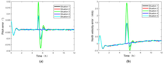
Figure 4.
Pitch angle error and north velocity error of externally measured velocity changes: (a) pitch angle error curve; (b) north velocity error curve.
The analysis of Figure 5 and Figure 6 shows that although the rate of change of the external measurement velocity error is different, when the amount of change is 2.5 m/s, the same level of change in the external measurement velocity error results in a dynamic overshoot error with the same amplitude as in cases 1, 2, and 5. When the variation of reference velocity errors increases, the dynamic overshoot amplitude of the system also increases, as in cases 2 and 3. When the change rate of reference velocity errors changes periodically, there is almost no overshoot error, as in case 4. Here, only the east horizontal loop is selected for explanation, and the results obtained by the north horizontal loop are consistent with it. Therefore, it can be obtained that the step and ramp measurement errors with the same reference velocity error change will cause the same overshoot error, and the amplitude of system overshoot error caused by periodic measurement error is significantly smaller than that of step and ramp measurement errors. Although the above three kinds of measurement errors will bring overshoot errors to the system, there are no steady-state errors.
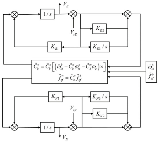
Figure 5.
Schematic diagram of digital compass circuit noise reduction.
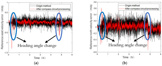
Figure 6.
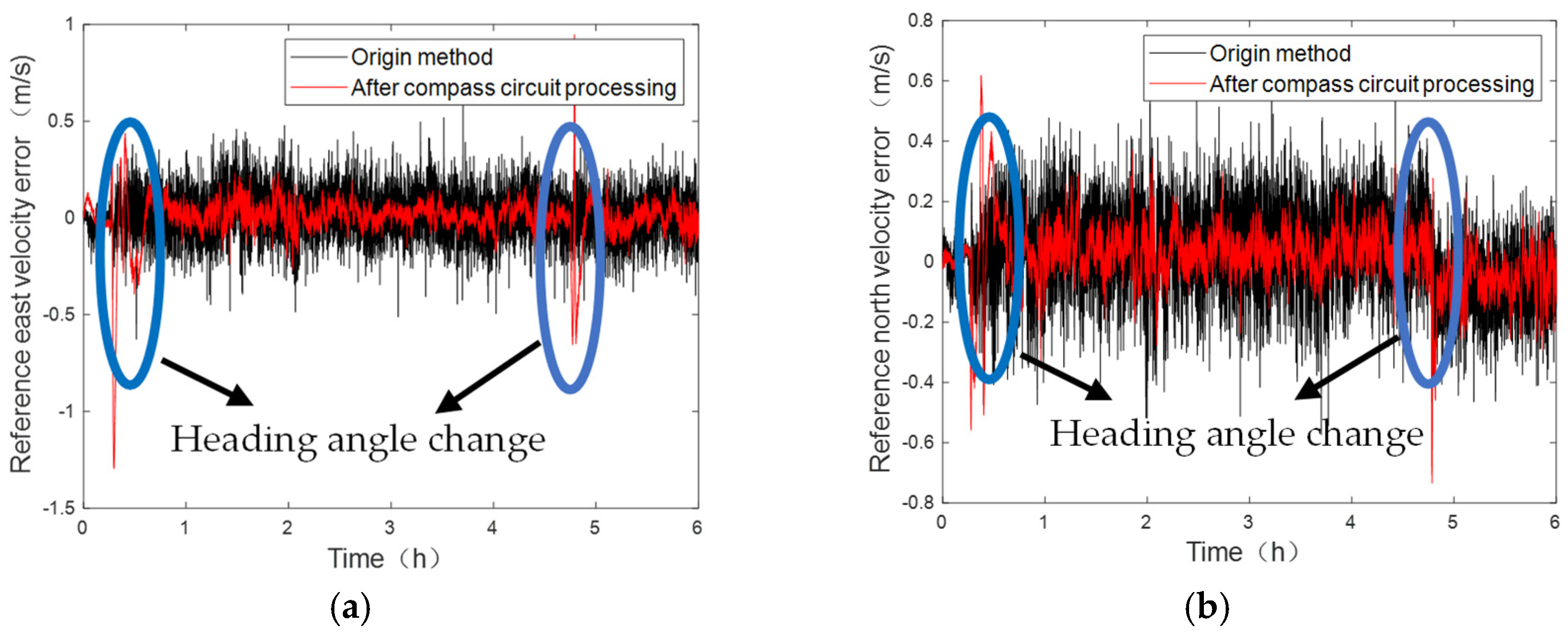
The application effect of the digital compass loop: (a) east reference velocity error curve before and after compass loop processing; (b) north reference velocity error curve before and after compass loop processing.
3.2. Principle of Damping State Switching Method Based on Support Vector Machine Detection
Under normal circumstances, when the ship or underwater vehicle is sailing, the reference velocity errors of different amplitudes have different effects on the system, so it is necessary to adjust the working mode of the system. There are mainly two ways: one is to switch the damping coefficient, and the other is to switch the damping state. Studies show that different damping coefficients cause only a small difference in the ability to suppress the errors of the external measurement velocity. Therefore, it is not advisable to suppress the error in order to change the damping coefficient [27]. Therefore, switching the damping state is more suitable for the suppression of reference velocity errors.
According to the analysis in the previous section, after the external measurement velocity is introduced, the physical quantity that affects the navigation error becomes the change rate of the reference velocity errors. In this paper, the damping state is switched according to the change in reference velocity errors. At this time, the damping coefficient of the system is constant at 0.5. Firstly, the definition of reference velocity error is defined as
where represent the measured velocity of SINS in the navigation system, the measured velocity of DVL, and the true velocity of the ship platform, respectively. Reference velocity error is defined as the difference between the measurement velocity of SINS and DVL, which is also equal to the difference between the measurement errors of the two sensors. According to the previous section, the variation of reference velocity errors at can be described as follows:
After giving the specific form of the reference velocity error change, the purpose of this paper is to use the reference velocity error change to switch the damping state. The average value of the reference velocity error in a certain period of time is selected as the equivalent change rate of the reference velocity errors. The specific form is given by
In Equation (11), n refers to the length of window detection, refers to the initial time of window detection, i represents the current time, and represent the velocity of SINS and DVL output at time i, and s represents the absolute change in reference velocity errors from to . The selection of window length determines the delay of the system. The larger the window length, the higher the discrimination accuracy of the reference velocity errors, but the longer the time delay. Therefore, it is very important to select the appropriate window length according to the accuracy and delay. In addition, the selection of s is of great significance for the switching of the damping state; [26] uses the simulation data to select s, but there are differences between the results obtained from the simulation data and the real data. Therefore, this paper proposes a discrimination method based on a support vector machine to switch the damping state. This method can effectively realize the automatic switching of the damping state. This method is also based on the measured data.
As a machine learning method, a support vector machine (SVM) has outstanding performance in small-sample, nonlinear, local-minimum, and other fields, especially in solving classification problems. SVM is a classifier based on the structural risk minimization principle, which divides the data into two types of a hyperplane through quadratic programming. Due to its robustness and effectiveness in the field of classification, this paper uses the trained SVM model to classify the damping state, so as to achieve the purpose of automatic damping state switching [29,30].
Firstly, the input samples need to be determined. For SINS, the vertical channel tends to diverge. This paper mainly studies the horizontal damping loop, so only the east and north velocity channels are considered. Since the abnormal condition of the channel for the external reference velocity error is not fixed, it is inappropriate to use only two channels as input samples. Therefore, we treat the two velocity error channels as Equation (15).
where and represent the variation of reference velocity errors in the east and north directions, respectively. Using the sum of absolute values of reference velocity error change as input samples, the abnormal conditions of two velocity error channels can be reflected at the same time. Since the purpose of this paper is to use the machine learning method for sample training, in order to avoid the fuzziness of a sample interval, it is necessary to further highlight the characteristics of reference velocity errors. In order to further highlight the characteristics of reference velocity errors, the digital compass loop is innovatively introduced for noise reduction [31]. The digital compass loop is similar to the process of an SINS solution. Through integral operation, the disturbance of horizontal velocity can be well attenuated. The purpose of using the digital compass circuit must be specified here. Firstly, it can better highlight the data segment containing velocity measurement errors. Secondly, it can reduce the reference velocity errors. Thirdly, the processing of a digital compass loop is carried out in real time. The purpose of introducing a digital compass loop is more focused on the first characteristic. The principle diagram of external measurement of velocity disturbance attenuation using a digital compass circuit is shown in Figure 5 [31].
Based on the measured data, the application effect of the digital compass loop is shown by Figure 6. The parameters of the digital compass loop are [32]. This is the result of many times performing debugging.
From the above experimental results, it can be seen that during the period when the velocity measurement errors are abnormal, the test ship has made a turn with a large yaw angle during the voyage. Therefore, compared with the normal navigation, the abnormality of the velocity measurement errors is more obvious. After using the digital compass loop, the abnormal errors in the velocity measurement are more obvious, and the errors in the reference velocity measurement are reduced to a certain extent.
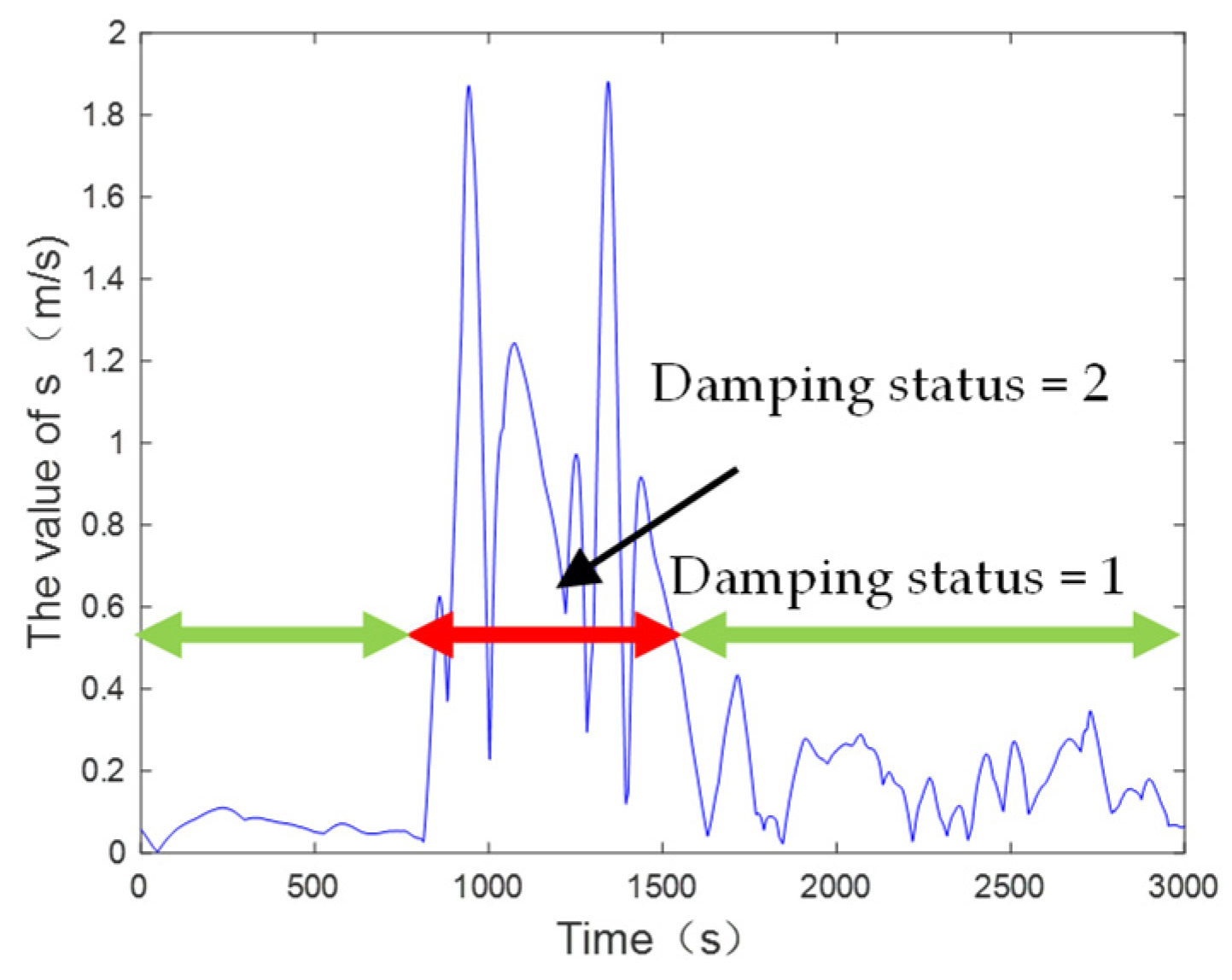
After the input samples of the SVM are determined and processed by the digital compass loop, the damping state switching is further explained here. Firstly, using a piece of data with obvious measurement velocity errors collected in advance, the change in reference velocity errors is calculated through window detection, which is used as the input sample of SVM, and the trained model is used in the subsequent navigation process. After collecting a data sample containing velocity measurement errors, and calculating the corresponding s value, the data segment is divided into two or more segments with damping states of 1 and 2, respectively. The data division bases here are mainly from the beginning to the end of actions that cause velocity measurement errors such as large-scale heading maneuvers. Figure 7 shows the specific division curve of the damping state.
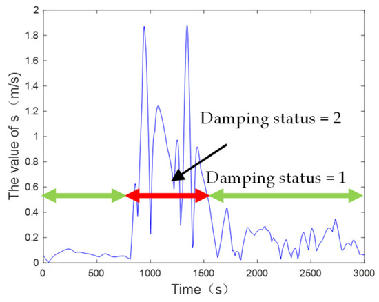
Figure 7.
Input sample division diagram.
When using SVM to identify the damping state, its internal structure must be clear. Firstly, the kernel function selects the radial basis function, in which the penalty factor and the kernel function coefficient have a great impact on the training effect of the model. The penalty factor reflects the dependence on empirical risk and structural risk, and the kernel function coefficient determines the complexity of data distribution in the high-dimensional data space. In order to achieve the highest classification accuracy, the cross-validation method is used to obtain the optimal support vector machine parameters through multiple cycles of iteration within the set parameter range. The specific results of the parameter optimization process are shown by Figure 8. We use integer units of lg to make the parameters g and c non-decimal, which is clearer and more intuitive. Accuracy (%) represents the classification accuracy of the support vector machine. After multiple optimizations, the optimal parameters and are determined, and the highest classification accuracy is 96.5%.
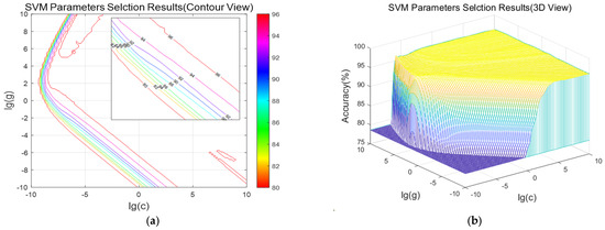
Figure 8.
The specific results of the parameter optimization process: (a) SVM parameter selection results (contour view); (b) SVM parameter selection results (3D view).
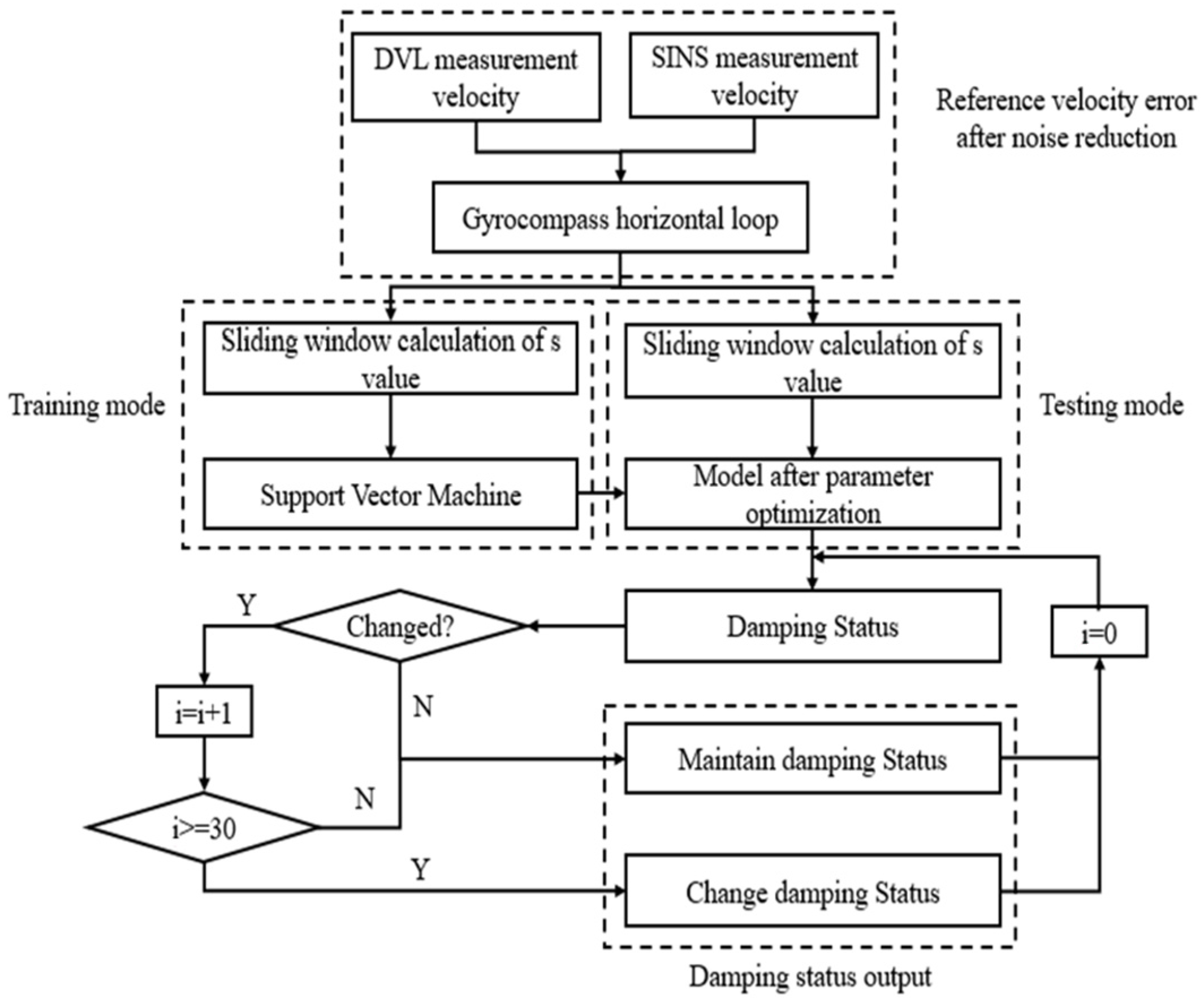
According to the s calculated from the measured data, the value at a certain time is small, but it is in the opposite damping state. Therefore, in order to avoid frequent switching of the damping state, we make the following provisions for the damping state results. When the SVM model outputs the damping state opposite to the previous time, it will switch the damping state when it outputs the same damping state for the next 30 consecutive times; otherwise, it will continue to maintain the original damping state. The flow chart of damping state switching using SVM is illustrated in Figure 9.
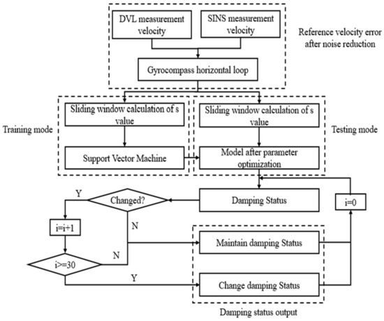
Figure 9.
Flow chart of damping state switching based on SVM.
3.3. Overshoot Error Suppression Principle
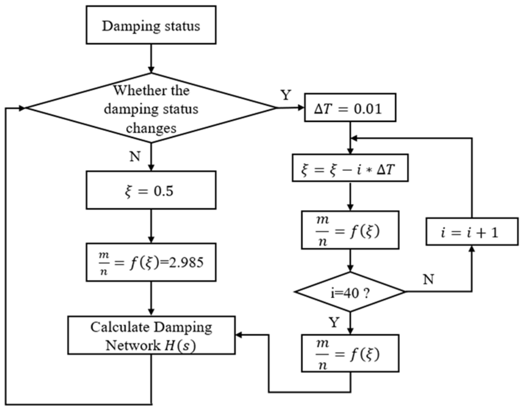
After using SVM to judge the damping state, damping switching is required. In order to save cost, the traditional damping state switching method is usually used in practical engineering. This manual switching method has the following two disadvantages: (1) It consumes manpower, and manual switching reduces the security and reliability of the system. (2) One switching of a damping coefficient will bring overshoot error. In order to further improve the existing schemes, it is necessary to study a reliable damping automatic switching and stable switching method. The automatic switching method based on SVM introduced in the previous section can effectively solve the problem of damping state switching. In addition, it is necessary to undertake measures to smoothly switch the damping coefficient. The change in the damping coefficient directly affects the change in the damping network, and then affects the overshoot of system output. Therefore, changing the direct switching of the damping coefficient to gradual switching can effectively reduce the overshoot output of the system. The specific idea is to adjust the step of damping coefficient switching when the damping state switching is detected, and change the original step change damping coefficient into a gradual change damping coefficient, so as to reduce the system overshoot error. The flow chart of overshoot error suppression is shown in Figure 10.

Figure 10.
Overshoot error suppression flow chart.
4. System Simulation Test
In order to verify the effectiveness of the proposed method, simulation experiments are carried out in this section. Firstly, assume that the initial position of SINS is 20° N and 120° E, and the initial attitude angle is 20°, 20°, and 120°. In the inertial device of SINS, the gyroscope drift biases in three orthogonal directions are , the random walk coefficient of the gyroscope is , and the accelerometer drift biases are . The random walk coefficient of the accelerometer is . The initial position errors in the horizontal direction are , the initial velocity errors are 0.1 m/s, and the initial attitude errors are, respectively, 0.25′, 0.25′ and 0.5′. The external measurement velocity is obtained by superimposing the real velocity with Gaussian white noise, and the intensity of Gaussian white noise is . The motion state of the ship is as follows: the ship is in a static state for the first 5 h. After 5 h, the ship accelerates at for 500 s until the speed is , and then starts to move at a constant velocity. The simulation lasts for 24 h and the simulation step is 1 s.
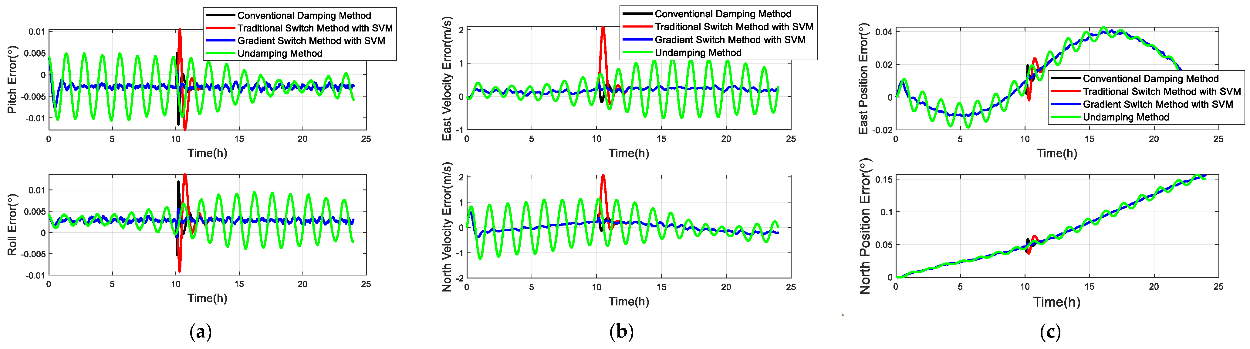
The actual inertial navigation data are generated by the track generator. In order to simulate the velocity errors of DVL in the real environment, we make the following settings. At 10 h, the DVL velocity measurement error is changed from 0 m/s to in 300 s, and then the DVL velocity measurement errors are changed to 0 with the same acceleration. The external reference velocity is generated in the same way. Here, we use three methods for comparison: (1) There is an external reference velocity error in the system, and the damping coefficient of the damping network is always 0.5. (2) There are external reference velocity errors in the system. SVM is used to detect the external reference velocity errors, and switch the damping state in real time, and the overshoot error suppression method is not used. (3) The external reference velocity errors exist in the system. SVM is used to detect the external reference velocity error, switch the damping state in real time, and use the overshoot error suppression method. The comparison of the above three methods shows the effectiveness of the SVM detection method and the overshoot error suppression method. The simulation test error analysis is shown in Figure 11.
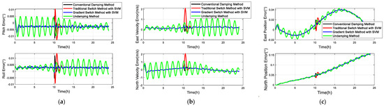
Figure 11.
Simulation test error analysis: (a) horizontal attitude angle error comparison; (b) velocity error comparison; (c) position error comparison.
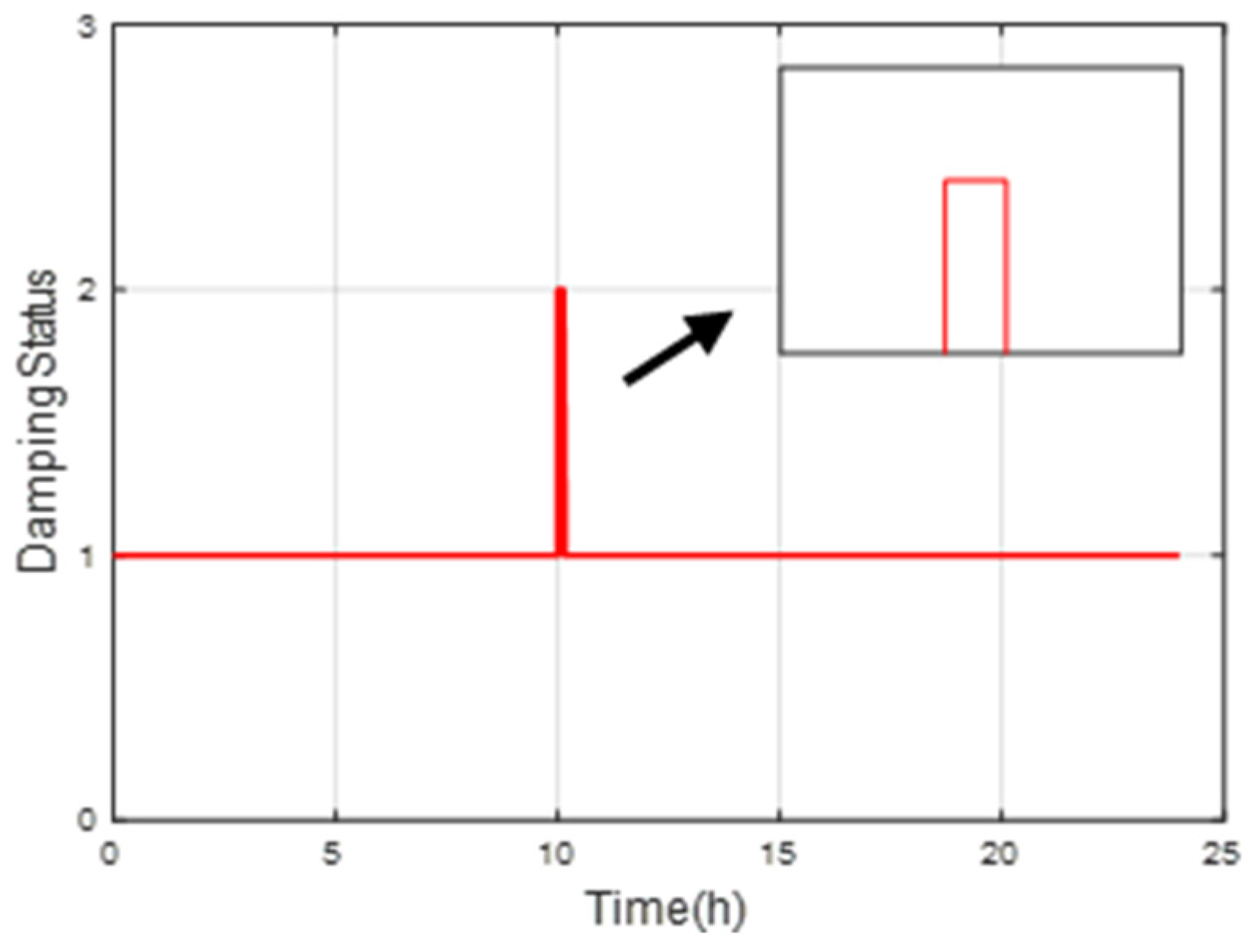
At 5 h, firstly, it can be seen from Figure 12 that the vehicle has moved from a stationary position. At this time, the acceleration of the vehicle is well compensated for due to the external damping method, so there is no overshoot error caused by the acceleration of the vehicle. From about 10 h, overshoot errors began to appear due to the introduction of DVL velocity measurement errors. From the four error curves, it can be seen that for the fixed damping coefficient method, since the damping coefficient has not changed, the velocity measurement errors of DVL will affect the system, so the overshoot error it produces is significantly higher than that of the other two methods. At this time, the overshoot error peaks of the horizontal attitude angle are and . After using the SVM method to detect the external reference velocity errors, the damping state of the system is switched to the undamped state, so theoretically the overshoot error will decrease. However, the traditional one-time damping state switching is still used in the switching mode, so the overshoot error will still occur. At this time, the peak overshoot error of the horizontal attitude angle is and . At the same time, the overshoot error is effectively reduced by using support vector machine detection and damping gradient switching. At this time, the overshoot error peaks of the horizontal attitude angle are and , respectively. Compared with the other two methods, the peak values of horizontal attitude angle overshoot error have been reduced by 93.75%, 58.88% and 92.38%, 52.85%, respectively. For the velocity error curve and the position error curve, it can be seen that the overshoot error produced by the traditional fixed damping method and the one-time switching variable damping method is much greater than the new method combined with SVM detection and gradual damping. First of all, the main content of this paper is to reduce the overshoot error caused by the external reference velocity error. When the overshoot error occurs, the state of the strapdown inertial navigation system needs to be switched to an undamped state. This strategy can improve the navigation accuracy of the system. Secondly, the role of the support vector machine is to be able to relatively accurately identify these damping states and achieve automatic switching. The introduction of this method reduces the degree of human involvement and improves the measurement accuracy of the system. Finally, the change curve of the damping state is given by Figure 12. It is not difficult to see that using SVM for detection can well switch the damping state according to the change in reference velocity error.
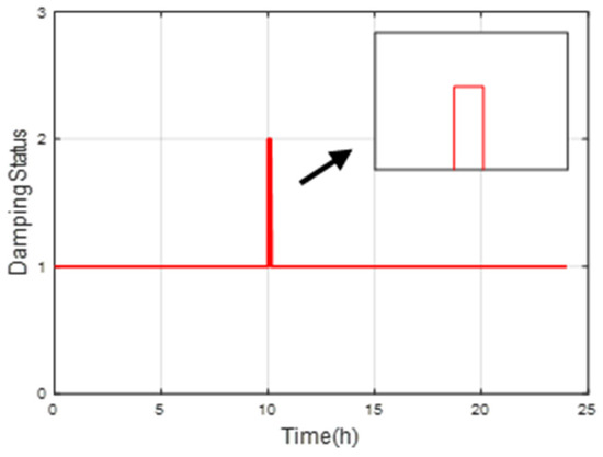
Figure 12.
Damping state change curve of simulation test.
5. Ship Testing and Verification
In order to further verify the effectiveness of the method proposed in this paper, a ship-borne test was carried out in the Yangtze River Basin in Badong County, Hubei Province, and the river surface flow in the test area was smooth. The onboard equipment of the test vessel includes a navigation level accuracy IMU in Table 1, a single antenna GPS receiver, and a DVL in Table 2. Specific parameters of test equipment are as follows:

Table 1.
Specifications of IMU.
Table 2.
Specifications of DVL.
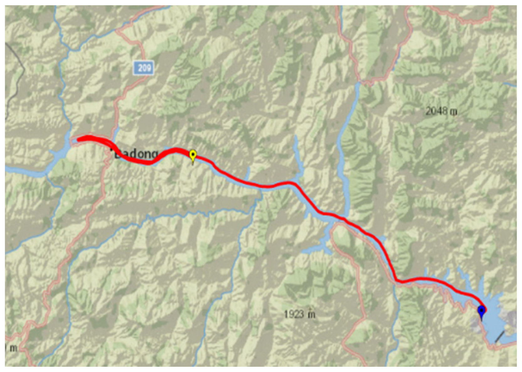
The test duration is 6 h in total. During the whole test, GPS works normally to provide effective velocity and position information. The reference information in the experiment is provided by SINS/GPS-integrated navigation results, including attitude, velocity, and position information. The track diagram of the experiment process is given by Figure 13.
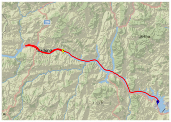
Figure 13.
Track diagram of ship test of damping state change.
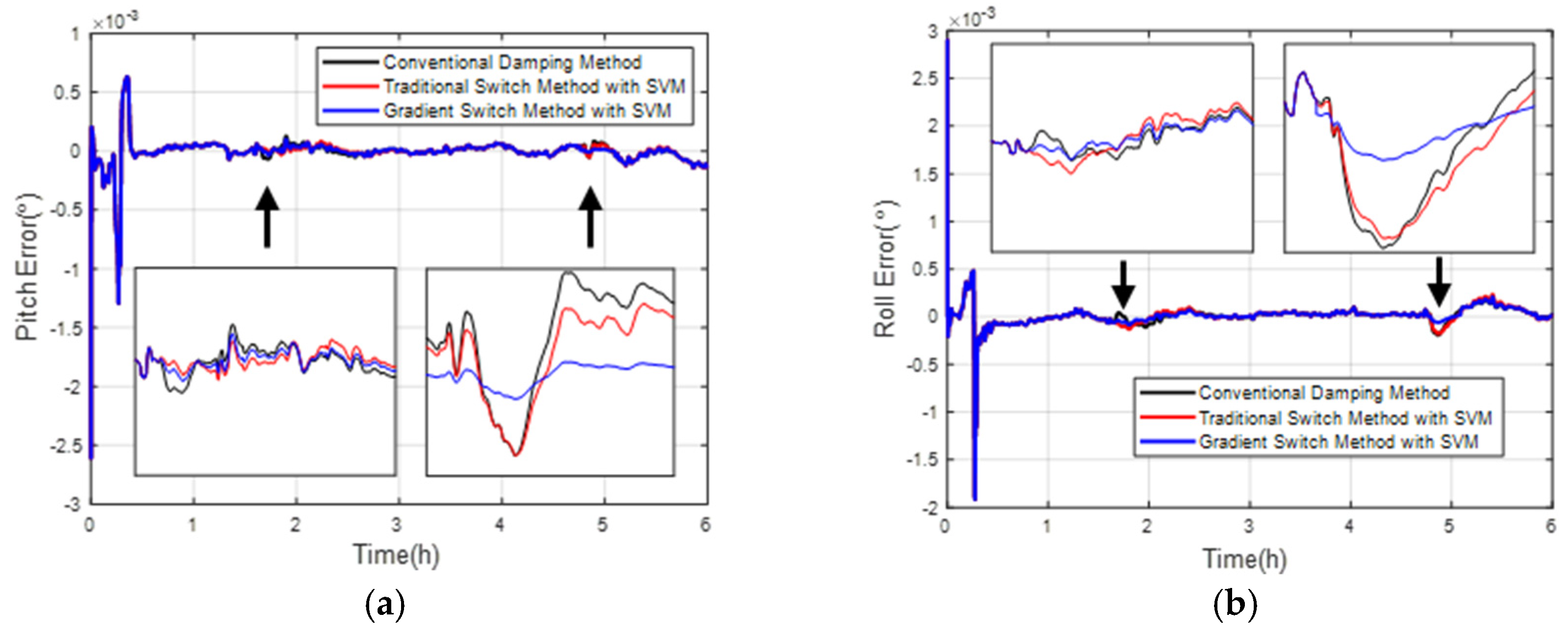
During the test, there is a large heading angle change at about , and there are DVL velocity measurement errors at this time. In order to further illustrate the effectiveness of the method proposed in this paper and fully simulate the velocity measurement errors generated in the real environment, the DVL velocity measurement errors are artificially added. When , the DVL velocity measurement error changes from to in 100 s, and then decreases to 0 after 100 s at the same acceleration. The method adopted in this section is consistent with that in the simulation. The detection model using SVM has been introduced in Section 3. The results of each navigation error are shown in Figure 14, Figure 15 and Figure 16.
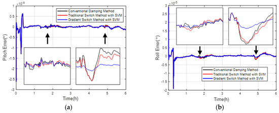
Figure 14.
Ship horizontal attitude error comparison: (a) pitch error curve; (b) roll error curve.
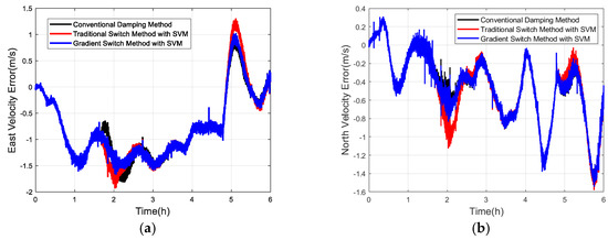
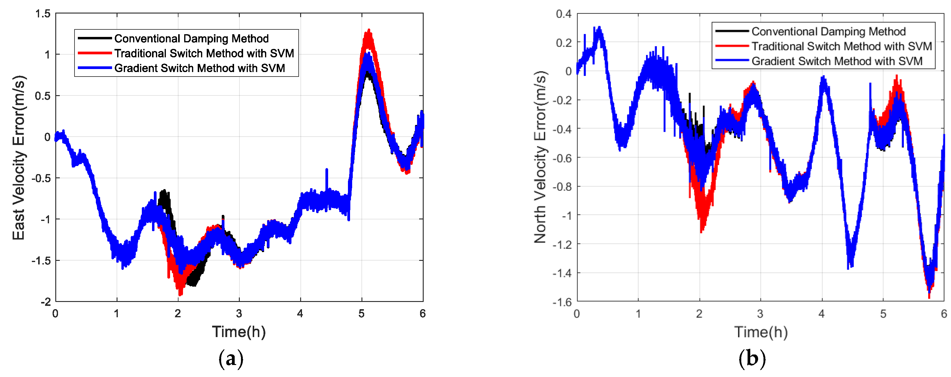
Figure 15.
Ship velocity error comparison: (a) east velocity error curve; (b) north velocity error curve.
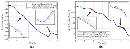
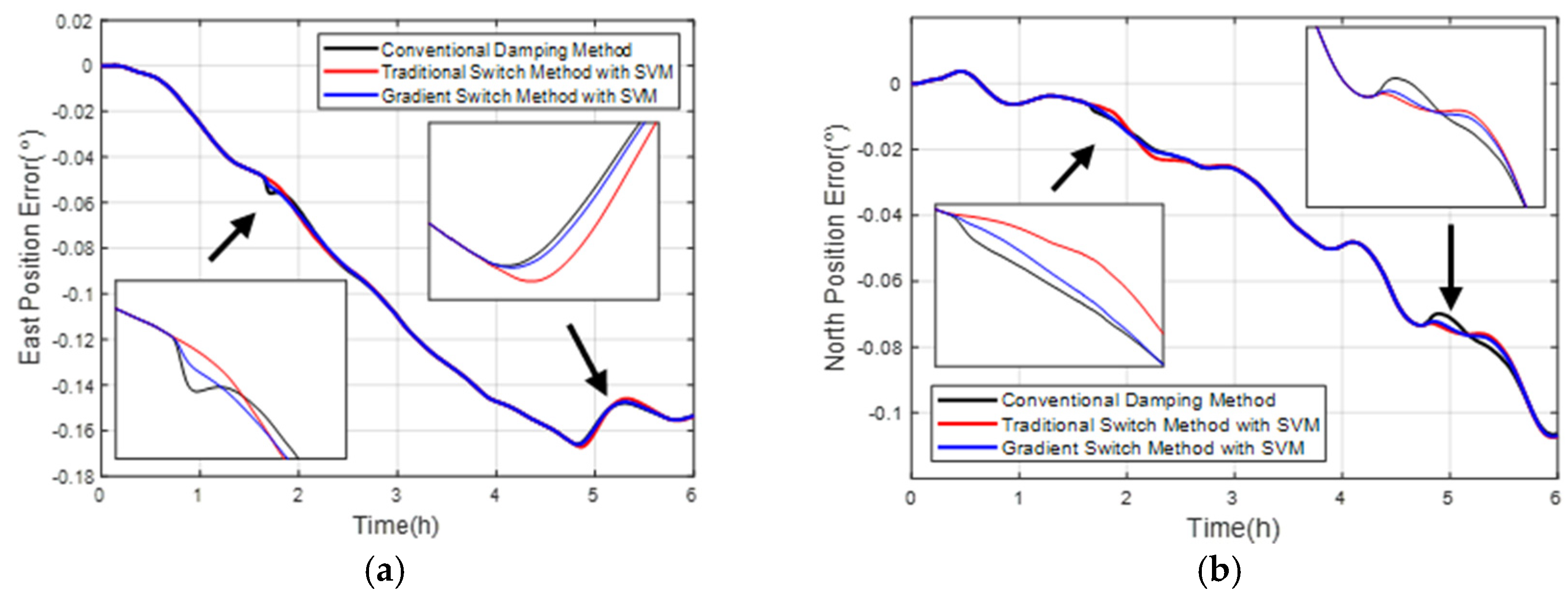
Figure 16.
Ship position error comparison: (a) east position error curve; (b) north position error curve.
Compared with the simulation results, the overshoot effect is not obvious in the measured data, which may be due to the fact that the experiment takes place in the Yangtze River Basin with a relatively gentle hydrological environment. According to the horizontal attitude angle error calculated from the experimental data, there are large DVL velocity measurement errors in the whole process in two time periods. At this time, the traditional fixed damping coefficient method and the primary damping switching method have produced overshoot errors to varying degrees. The overshoot error has decreased by using the method proposed in this paper, and the error has reached the same after an approximate Schuler oscillation cycle. From the velocity error curve and position error curve, the fixed damping coefficient and damping state switching will lead to overshoot error. The method in this paper can effectively avoid overshoot error by using SVM to detect and gradually adjust the damping state. The change curve of the damping state is given by Figure 17. In addition, the damping state curve also reflects the interval with reference velocity error. The method proposed in this paper can suppress the overshoot error and effectively improve the accuracy of the navigation system.
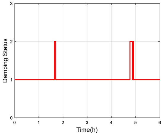
Figure 17.
Damping state change curve of ship test.
6. Conclusions
When SINS is in the traditional external damping mode, the velocity measurement errors will be brought to DVL by the operation of the ship acceleration and deceleration and large maneuvering turn. For DVL operating in the ground mode, this will seriously restrict the navigation accuracy. In order to effectively avoid the influence of reference velocity errors on SINS, the damping state should be switched. To solve this problem, this paper first proposes to use the digital compass loop to process the reference velocity errors, and successfully highlights the time period of the reference velocity errors. A method combining SVM with sliding window detection is proposed to detect the reference velocity errors. When the reference velocity errors are large, the damping state switch can be switched automatically. In addition, in order to reduce the impact of damping state switching, a variable damping system is used to change the traditional one-time switching of the damping coefficient into gradual switching, which effectively reduces the impact of sudden change in the damping coefficient on the system. Finally, the effectiveness of the proposed method is verified by simulation and a ship-borne semi-physical simulation test. Compared with the fixed damping coefficient method and the primary damping switching method, the method can effectively attenuate the influence of reference velocity errors, and has important engineering value in the application of actual ship navigation and underwater vehicles.
Author Contributions
Conceptualization, X.L. and J.Z.; methodology, X.L., J.Z. and J.W.; validation, J.Z. and J.W.; writing—original draft preparation, J.Z.; writing—review and editing, X.L., R.D., S.Q. and B.H.; funding acquisition, X.L. All authors have read and agreed to the published version of the manuscript.
Funding
This work was supported by the Basic Science Center Program of the National Natural Science Foundation of China (62388101) and China Postdoctoral Science Foundation (2023M741882).
Data Availability Statement
The original contributions presented in the study are included in the article, further inquiries can be directed to the corresponding author.
Conflicts of Interest
The authors declare no conflicts of interest.
References
- Zhu, J.; Li, A.; Qin, F.; Chen, H.; Wang, J. A novel hybrid method based on deep learning for an integrated navigation system during DVL signal failure. Electronics 2022, 11, 2980. [Google Scholar] [CrossRef]
- Gao, D.; Hu, B.; Chang, L.; Qin, F.; Lyu, X. An Aided Navigation Method Based on Strapdown Gravity Gradiometer. Sensors 2021, 21, 829. [Google Scholar] [CrossRef]
- Mao, N.; Li, J.; He, H.; Xu, J. Attitude Estimation of SINS on Dynamic Base with Decoupling Gravity Vector. IEEE Sens. J. 2021, 21, 20530–20538. [Google Scholar] [CrossRef]
- Lyu, X.; Hu, B.; Li, K.; Chang, L. An Adaptive and Robust UKF Approach Based on Gaussian Process Regression-Aided Variational Bayesia. IEEE Sens. J. 2021, 21, 9500–9514. [Google Scholar] [CrossRef]
- Karmozdi, A.; Hashemi, M.; Salarieh, H.; Alasty, A. Implementation of Translational Motion Dynamics for INS Data Fusion in DVL Outage in Underwater Navigation. IEEE Sens. J. 2021, 21, 6652–6659. [Google Scholar] [CrossRef]
- Kudryashov, A.; Inzartsev, A. A Technique to Navigate Autonomous Underwater Vehicles Using a Virtual Coordinate Reference Network during Inspection of Industrial Subsea Structures. Remote Sens. 2022, 14, 5123. [Google Scholar] [CrossRef]
- Wang, D.; Xu, X.; Yao, Y.; Zhang, T. Virtual DVL Reconstruction Method for an Integrated Navigation System Based on DS-LSSVM Algorithm. IEEE Trans. Instrum. Meas. 2021, 17, 8501913. [Google Scholar] [CrossRef]
- Xu, B.; Wang, L.; Li, S.; Zhang, J. A Novel Calibration Method of SINS/DVL Integration Navigation System based on Quaternion. IEEE Sens. J. 2020, 20, 9567–9580. [Google Scholar] [CrossRef]
- Qin, Y. Inertial Navigation; Beijing Science Press: Beijing, China, 2006. [Google Scholar]
- Liu, F.; Liu, C.; Weng, H.; Hu, X. Level damping algorithm of sins based on kalman filtering. J. Chin. Inert. Technol. 2013, 21, 285–288. [Google Scholar]
- Qin, F.; Li, A.; Xu, J. Improved internal damping method for inertial navigation system. J. China Inert. Technol. 2013, 2, 147–154. [Google Scholar]
- Li, Q.; Ben, Y.; Sun, F. A novel algorithm for marine strapdown gyrocompass based on digital filter. Measurement 2013, 46, 563–571. [Google Scholar] [CrossRef]
- Xu, B.; Wang, G.; Bai, J. Optimal design of damping network based on DVL velocity and IMU. Ocean Eng. 2017, 132, 101–113. [Google Scholar] [CrossRef]
- Kasper, J.F.; Nash, R.A. Doppler Radar Error Equations for Damped Inertial Navigation System Analysis. IEEE Trans. Aerosp. Electron. Syst. 1975, 11, 600–607. [Google Scholar] [CrossRef]
- Sun, J.; Xu, X.; Liu, Y.; Zhang, T.; Tong, J. An adaptive damping network designed for strapdown fiber optic gyrocompass system for ships. Sensors 2017, 17, 494. [Google Scholar] [CrossRef]
- Zhao, L.; Li, J.; Cheng, J.; Hao, Y. Damping strapdown inertial navigation system based on a kalman filter. Meas. Sci. Technol. 2016, 27, 115102. [Google Scholar] [CrossRef]
- Huang, W.; Fang, T.; Luo, L.; Zhao, L.; Che, F. A damping grid strapdown inertial navigation system based on a kalman filter for ships in polar regions. Sensors 2017, 17, 1551. [Google Scholar] [CrossRef]
- Qian, N.; Chang, G.; Guo, J.; Shen, W.; Yan, Z. Adaptive DDK Filter for GRACE Time-Variable Gravity Field with a Novel Anisotropic Filtering Strength Metric. Remote Sens. 2022, 14, 3114. [Google Scholar] [CrossRef]
- Zha, F.; Qin, F.; Li, F.; Ye, B. Fast external damping algorithm of inertial guidance system under external velocity reference condition. J. Wuhan Univ. 2019, 44, 398–404. [Google Scholar]
- Qin, F.; He, H.; Xu, J. Phase modulation-based sins damping method for autonomous vehicles. IEEE Sens. J. 2018, 18, 2483–2493. [Google Scholar]
- Qin, F.; Li, A.; Xu, J.; Zha, F. Horizontal inner damping method with continuously adjustable parameter for inertial navigation system. J. Chin. Inert. Technol. 2011, 19, 290–292+301. [Google Scholar]
- Yu, P.; Yang, G. An adaptive level damped algorithm based on PINS for ship. Adv. Mater. Res. 2013, 760, 2162–2166. [Google Scholar] [CrossRef]
- He, J.; Sun, C.; Zhang, B.; Wang, P. Variational Bayesian-based maximum correntropy cubature Kalman filter with both adaptivity and robustness. IEEE Sens. J. 2020, 21, 1982–1992. [Google Scholar] [CrossRef]
- Li, Q.; Ben, Y.; Sun, F. Strapdown fiber optic gyrocompass using adaptive network-based fuzzy inference system. Opt. Eng. 2014, 53, 014103. [Google Scholar] [CrossRef]
- Deng, Z.; Sun, J.; Ding, F.; Ismail, M.W.M. A novel damping method for strapdown inertial navigation system. IEEE Access 2019, 7, 49549–49557. [Google Scholar] [CrossRef]
- Liu, C.; Wu, Q.; Hu, P.; Zhang, R. Design of variable damping INS for ships based on the variation of reference velocity error. J. Sens. 2021, 2021, 6628073:1–6628073:15. [Google Scholar] [CrossRef]
- Qin, F.; Chen, Y.; Zha, F.; Chang, L. Marine Inertial Navigation Principle; National Defence Industry Press: Beijing, China, 2018. [Google Scholar]
- Jiang, L.; Yu, Y.; Chen, Y. An adaptive-damping network designed for inertial navigation system of ships. Electron. Opt. Control 2014, 21, 52–57. [Google Scholar]
- Zhu, J.; Li, A.; Qin, F.; Chang, L. A New Robust Adaptive Filter Aided by Machine Learning Method for SINS/DVL Integrated Navigation System. Sensors 2022, 22, 3792. [Google Scholar] [CrossRef]
- Xu, J.; Zeng, W.; Lan, Y.; Guo, J.; Cheng, X. Modeling the parameter interactions in ranking svm with low-rank approximation. IEEE Trans. Knowl. Data Eng. 2019, 31, 1181–1193. [Google Scholar] [CrossRef]
- Wang, B.; Huang, L.; Liu, J.; Deng, Z.; Fu, M. A support vector regression-based integrated navigation method for underwater vehicles. IEEE Sens. J. 2020, 20, 8875–8883. [Google Scholar] [CrossRef]
- Xu, J.; He, H.; Qin, F.; Chang, L. A novel autonomous initial alignment method for strapdown inertial navigation system. IEEE Trans. Instrum. Meas. 2017, 66, 2274–2282. [Google Scholar] [CrossRef]


Disclaimer/Publisher’s Note: The statements, opinions and data contained in all publications are solely those of the individual author(s) and contributor(s) and not of MDPI and/or the editor(s). MDPI and/or the editor(s) disclaim responsibility for any injury to people or property resulting from any ideas, methods, instructions or products referred to in the content. |
© 2024 by the authors. Licensee MDPI, Basel, Switzerland. This article is an open access article distributed under the terms and conditions of the Creative Commons Attribution (CC BY) license (https://creativecommons.org/licenses/by/4.0/).