Article

A Scalable Multi-FPGA Platform for Hybrid Intelligent Optimization Algorithms

1
School of Computer Science, Beijing Information Science & Technology University (BISTU), Beijing 100080, China
2
Institute of Automation, Chinese Academy of Sciences, Beijing 100190, China
*
Author to whom correspondence should be addressed.
Electronics 2024, 13(17), 3504; https://doi.org/10.3390/electronics13173504
Submission received: 26 June 2024 / Revised: 31 August 2024 / Accepted: 1 September 2024 / Published: 3 September 2024

Abstract

:
The Intelligent Optimization Algorithm (IOA) is widely focused due to its ability to search for approximate solutions to the NP-Hard problem. To enhance applicability to practical scenarios and leverage advantages from diverse intelligent optimization algorithms, the Hybrid Intelligent Optimization Algorithm (H-IOA) is employed. However, IOA typically requires numerous iterations and substantial computing resources, resulting in poor execution efficiency. In complex optimization scenarios, IOA traditionally relies on population partitioning and periodic communication, highlighting the feasibility and necessity of parallelization. To address the challenges above, this paper proposes a general hardware design approach for H-IOA based on multi-FPGA. The approach includes the hardware architecture of multi-FPGA, inter-board communication protocols, population storage strategies, complex hardware functions, and parallelization methodologies, which enhance the computing capabilities of H-IOA. To validate the proposed approach, a case study is conducted, in which an H-IOA integrating genetic algorithm (GA), a simulated annealing algorithm (SA), and a pigeon-inspired optimization algorithm (PIO) are implemented on a multi-FPGA platform. Specifically, the flexible job-shop scheduling problem (FJSP) is employed to verify the potential in industrial applications. Two Xilinx XC6SLX16 FPGA chips are used for hardware implementation, encoded in VHDL, and an AMD Ryzen 7 5800U was used for the software implementation of Python programs (version 3.12.4). The results indicate that hardware implementation is 13.4 times faster than software, which illustrates that the proposed approach effectively improves the execution performance of H-IOA.

1. Introduction

The Intelligent Optimization Algorithm (IOA) has gained significant attention due to the IOA’s capability to approximate solutions for NP-Hard problems. Using the IOA, researchers and practitioners can find optimal solutions to NP-Hard problems which are difficult or impossible for traditional methods [1]. IOA uses intelligent search techniques to explore the solution space and find the best solution, based on a set of criteria or objectives. The intelligent search ability of IOA is typically inspired by natural systems, such as the behavior of swarms of insects or the evolution of species, which can develop search strategies which can efficiently explore large solution spaces [2,3,4]. The IOA is used wildly in various fields due to its strong versatility, robustness, and adaptive adjustment.
With the development of cloud computing, the Internet of Things (IoT), Smart Manufacturing, and other advanced technologies, resource distribution becomes increasingly diverse, which spurs the development of various intelligent optimization algorithms (IOAs) to meet efficient scheduling. To this end, various IOAs are widely applied, such as Genetic Algorithms (GA) [5], Particle Swarm Optimization (PSO) [6], Ant Colony Optimization (ACO) [7], Simulated Annealing (SA) [8], etc.
Research on improving Intelligent Optimization Algorithms (IOAs) has garnered significant attention and is primarily categorized into two main approaches: operator modification and algorithm hybridization. The operator modification is further divided into three subclasses: adjusting operator parameters, modifying operator structures, and integrating new operators. One study [9] improves the performance of the algorithm by adding crossover operators. The algorithm parameters are modified in the literature [10], thus improving the performance of the algorithm. Another study [11] combines two operators; the structure of the algorithm is changed and the performance is improved. The hybridization of the intelligent optimization algorithm is an important means of improving the algorithm. The IOA has many common characteristics that allow algorithms to be hybridized. The intelligent optimization algorithm solution process is actually a continuous iteration process of the population, in which each individual in the population represents a solution. After a continuous iteration of the population, the solution represented by the individual reaches the approximate optimal solution. A large proportion of initial populations and coding schemes can be used by a variety of intelligent optimization algorithms. The hybridization of algorithms focuses on the recombination and redistribution of operators in the iterative process. By recombining or redistribution parts of the intelligent optimization algorithm, a hybrid version of the intelligent optimization algorithm can be obtained. The hybridization algorithm can combine the advantages of different algorithms to form a more efficient algorithm. One study [12] hybridizes the GA and PSO algorithm, and the exploration ability of GA and the exploitability of PSO are used to improve the overall performance.
With the background of intelligence in various fields, scheduling problems are more and more complicated. Most studies improving IOA put more emphasis on mathematical methods, and how to execute IOA in a shorter time is not elaborated, especially while faced with complex problems. Due to the complexity of scheduling problems, algorithms require more computing resources and iterative processes during execution. The defect limits the application of the algorithm to practical scheduling problems. Fortunately, in the intelligent optimization algorithm, the individuals are independent of each other, and the dimensions within the individuals are independent of each other, which is very suitable for parallel computing with a hardware platform to obtain the acceleration effect. A large number of intelligent optimization algorithms are proposed, most of which are not accelerated by hardware, which may result in the algorithm being unable to be applied due to poor real-time performance. Therefore, using parallel computing to accelerate IOA becomes an urgent problem to be solved.
Field Programmable Gate Array (FPGA) is a semiconductor device which is based around a matrix of configurable logic blocks (CLBs) connected via programmable interconnects. FPGA can be reprogrammed to desired application or functionality requirements after manufacturing. FPGA has powerful parallel computing capabilities and is widely used to improve the execution performance of algorithms. As scheduling problems become increasingly complex, a higher number of FPGAs are needed to achieve low latency, and even high-end FPGAs may not be able to accommodate a complex hybrid algorithm.
Overall, in complex optimization problems, many IOAs still have poor computing performance. Due to the independence of individuals within the IOA, it is feasible and necessary for multiple individuals to evolve in parallel to improve computing performance. The FPGA chip can be designed in parallel at the circuit level and can accelerate IOA effectively. However, if the optimization problem has a large scale, multiple variables, and needs a large population size, the limitation of FPGA logic resources will limit parallelism. Therefore, in order to improve the computing performance of IOAs in large-scale complex optimization problems, this paper proposes a general hardware platform based on multi-FPGA and summarizes the hardware design process. In order to verify the proposed platform and process, this work uses the platform and process to design a hardware program for the hybrid algorithm of GA, PSO, and SA. In addition, to validate that the proposed method is effective, the hardware design is applied to the FJSP problem.
The contributions of this research are listed below.
  • A general hardware platform is proposed based on multi-FPGA for hybrid intelligent optimization algorithms.
  • A general design flow is proposed based on multi-FPGA for hybrid intelligent optimization algorithms.
  • A hardware design case study is presented for the hybrid algorithm of GA, PIO, and SA with comparative and analytical results.
  • The potential of the hardware design case for implementation in industry is illustrated by applying the case to the FJSP problem.
The rest of the paper is organized as follows. Section 2 reviews the typical hardware design of the IOA. Section 3 describes the methodology. A case of the proposed method is carried out in Section 4. Section 5 compares and analyzes the experimental results. Section 6 concludes the paper.

2. Related Work

The main parallel computing platforms are distributed computing, GPU, ASIC, and FPGA [13,14]. Distributed computing splits a task into multiple subtasks which multiple processors execute, but the execution process is still essentially serial computation. As a hardware acceleration platform, the GPU makes achievements in many fields. However, the GPU has poor flexibility and high power consumption. FPGA is an integrated circuit consisting of an array of configurable logic blocks. FPGA can be programmed using hardware description languages such as VHDL or Verilog, allowing users to implement circuit logic arbitrarily. GPU is usually used for high-precision floating-point arithmetic, while FPGA can support computation with different precision, which makes FPGA an advantage in high-speed computation. ASIC is also commonly used for hardware acceleration. FPGA is programmable and has the flexibility to change the design, but ASIC requires re-customizing the circuit, which has a long development cycle and high cost. So, there are advantages to using FPGA to accelerate intelligent optimization algorithms.
Researchers use FPGA to accelerate some classic intelligent optimization algorithms such as the particle swarm optimization algorithm (PSO), the ant colony algorithm (ACO), the genetic algorithm (GA), etc. Huang et al. propose a method utilizing FPGA to accelerate PSO and apply the design to global route planning for autonomous robot navigation [15]. Costa et al. propose implementing the particle swarm optimization (PSO) algorithm using FPGA, analyzing the effect of population size on FPGA resource utilization and execution time [16]. B. Scheuermann et al. use FPGA to implement ACO and improve the performance of the compute [17]. In 2011, Masai et al. used FPGA to accelerate GA and designed a fuzzy controller [18]. Allaire et al. propose a genetic algorithm FPGA implementation for UAV computing path planning [19]. In addition, there are researchers who have accelerated the hybridization algorithm based on FPGA. Huang et al. use FPGA to accelerate the hybridization algorithm of GA and PSO and apply the design to the path planning of robots [20]. Hsu Chih Huang proposes a robot controller which is based on the ACO and PSO hybridization algorithm implemented by FPGA [21].
New intelligent optimization algorithms are proposed continually, such as the Whale Optimization Algorithm (WOA) [22], the Brain Storm Optimization (BSO) algorithm [23], the firefly algorithm [24], etc. Some algorithms are implemented in hardware to improve real-time performance [25,26,27]. However, others are not, which limits the ability of algorithms to be applied in practical applications.
The use of FPGA to accelerate intelligent optimization algorithms is shown to yield numerous benefits. However, most current solutions are based on a single-chip architecture, constrained by the limited logic resources available on the FPGA. A single FPGA is restricted by the available resources and compelled to trade-off time for space, thereby failing to exploit the potential of parallelism fully. Therefore, using multi-FPGA to accelerate intelligent optimization algorithms, especially hybrid intelligent optimization algorithms, is quite suitable. There are many benefits to using multi-FPGA. Firstly, multi-FPGA has more powerful computing performance, and multi-FPGA can process different data in parallel, achieving more efficient computation. Secondly, by increasing the number of FPGAs, multi-FPGA has scalability, and computing capacity can be easily expanded. Finally, multi-FPGA can accelerate complex algorithms. Multi-FPGA can provide the necessary computational power to achieve efficient operation for a substantial amount of computing resources tasks. One paper [28] accelerates the Convolutional Neural Network (CNN) based on multi-FPGA. Yuxi Sun and Hideharu Amano propose a multi-FPGA acceleration framework for deep recurring neural networks [29].

3. A General Hardware Platform and Hardware Design Flow Based on Multi-FPGA for Hybrid Intelligent Optimization Algorithms

In this section, a general hardware platform based on multi-FPGA for hybrid intelligent optimization algorithms is introduced. Then, the general design flow is proposed.

3.1. General Hardware Platform Based on Multi-FPGA for Hybrid Intelligent Optimization Algorithm

This chapter proposes a general hardware design based on multi-FPGA for the intelligent optimization algorithm from five aspects: hardware architecture, population storage, parallel design, board-level communication, and complex function design.

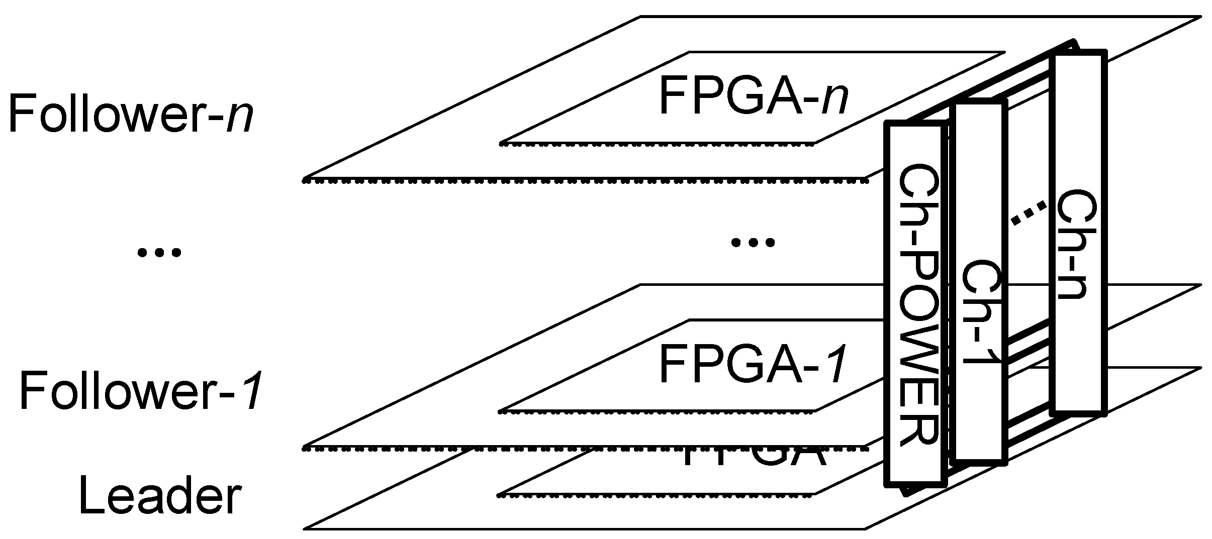
3.1.1. Hardware Architecture

The hardware architecture includes several development boards, each with a common set of peripheral pins and a stacked configuration (see Figure 1). Communication functions between the boards using Ch-1 to Ch-n. CH-POWER is the power supply pin. The architecture is designed to be scalable, allowing for the arbitrary expansion or reduction in development boards, provided the pins are appropriately aligned. Multiple development boards are configured in a leader–follower architecture, in which the leader board controls the overall process and executes simple computations. In contrast, the follower boards handle more complex computations. Complex computations involve floating-point arithmetic, exponentiation, and trigonometric functions, etc.
While the optimization problem is complex, with many variables, a large population size, and complex calculations, hardware implementation will be limited by chip logic resources. The logic resources of a single FPGA cannot achieve large-scale parallel complex calculations, resulting in sacrificing parallelism to save space. The proposed platform is scalable and can adapt to increasingly complex problems by increasing the number of FPGAs.

3.1.2. Population Storage

Population storage can be implemented in four ways: external memory, BRAM, DRAM, and register. These four methods reduce the storage capacity and increase flexibility (shown in Table 1). If the population is large, the first two methods are chosen for storage; if not, the latter are chosen. The first two implementation methods are appropriate if the logic resources inside FPGA are insufficient. The first two implementation methods do not occupy the logic resources inside the FPGA. In addition, the latter two options can be used to store sub-populations to enhance memory flexibility. FPGA has multiple BRAMs inside and can also be connected with multiple BRAMs outside. Therefore, multiple storage modules can be used flexibly for population storage according to needs. Therefore, the final choice of storage mode needs to be flexible according to the requirement.
In this work, the population is stored in the BRAM of the hardware module of the leader board. Sub-populations are stored in the follower board by a register group for more flexible access. The number of sub-populations is identical to the number of the development boards. The number of individuals within the sub-population is identical to the parallelism of the follower board.

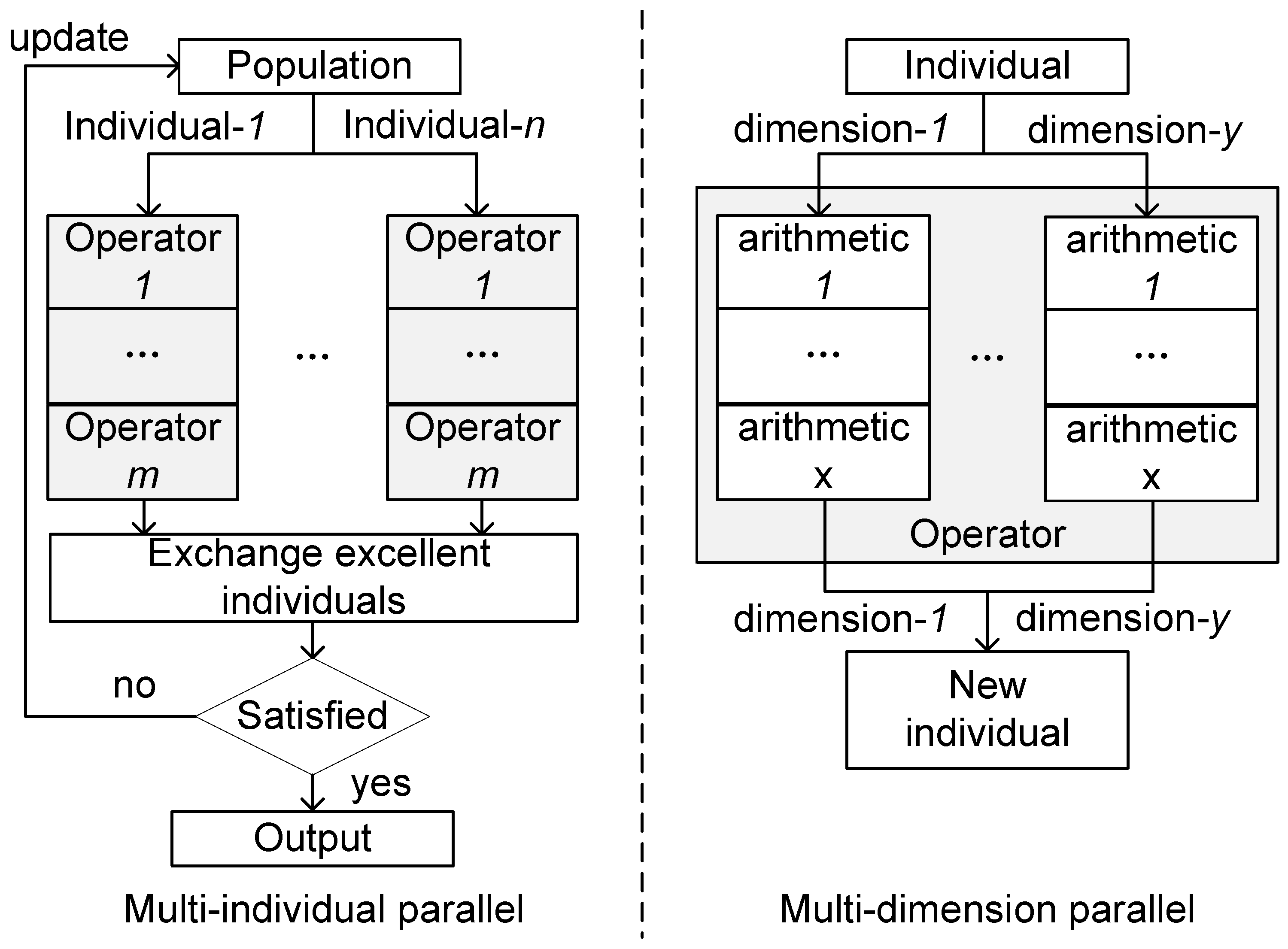
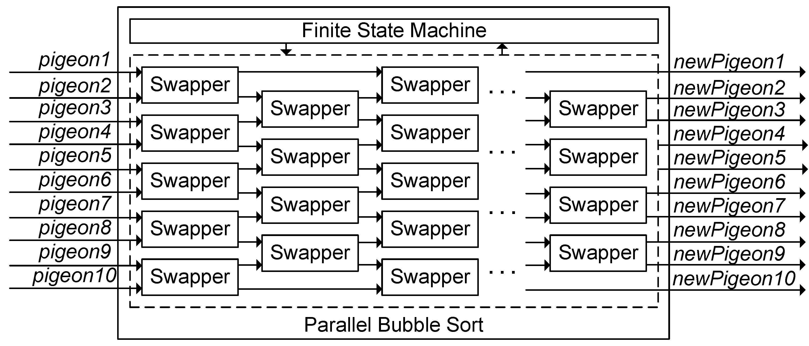
3.1.3. Parallel Processing

The solving process of intelligent optimization algorithms is based on population iteration, where the individuals within the population are independent, and the dimensions within the individuals are also independent. These independent characteristics are suitable for parallel design to accelerate computation. Therefore, the algorithm can be parallelized in two ways: the parallelization of multiple individuals and multiple dimensions, as shown in Figure 2. Multiple operator modules in multiple FPGAs should be instantiated, and multiple individuals should be moved in parallel according to the operator rules. Multiple dimensions within an individual can be computed in parallel to enable rapid evolution. For operations with high coupling, the computation can be decomposed into smaller modules and executed in a pipeline to improve the overall computational speed.
Operator modules are also instantiated on the leader board and can perform the evolution of a sub-population. Each follower board performs the evolution of a sub-population. The evolution of multiple sub-populations is parallel. In addition, individuals within each sub-population are also performed in parallel for evolution. Finally, the optimal solutions of multiple sub-populations are merged into the global optimal solution to complete the optimization process.

3.1.4. Inter-Board Communication

Communication in the algorithm mainly occurs between operators and during population updates. Board-level communication is required on this platform. The proposed platform supports three communication methods: shared memory communication, serial port communication, and parallel port communication. Shared memory communication is implemented using the BRAM hardware module inside the FPGA chip on the follower board. The address and data channel of the BRAM are fan-out and connected to the interfaces of other boards. The follower board stores data in the BRAM. Then, another board sends address channel data to BRAM. The data on the data channel are sampled at the next clock. So, once sampling needs two clock cycles. The width of the address and data channel can be customized. Assuming a data channel width of x and a clock frequency of yMHz, the communication rate is ( y 2 × x 8 ) MBPS. In this work, the data channel width used is 32, and at a clock frequency of 100 MHz, the communication rate is 200 MBPS. The serial port communication uses UART, and the baud rate supports a maximum of 230,400. Parallel communication directly connects the pins of the two development boards and completes data sampling through a handshake. The maximum waiting time for a handshake is four clocks, which means that data sampling can be completed once within the slowest four clocks. Assuming a clock frequency of yMHz and that the data channel has a width of x, the communication rate is y 4 × x 8 MBPS. The clock frequency used in this work is 100 Mhz, and the data channel width is 4, resulting in a communication rate of 12.5 MBPS. Due to the scalability of this platform, the number of follower boards is limited by the number of pins, so the balance between the number of communication-occupied pins and the number of FPGA development boards needs to be considered. Serial communication consumes fewer IO resources, but the implementation is more complex and requires complex communication protocols to transmit data packets. The shared storage method supports asynchronous communication, where the sender stores the data in BRAM, and the receiver can retrieve the data later.

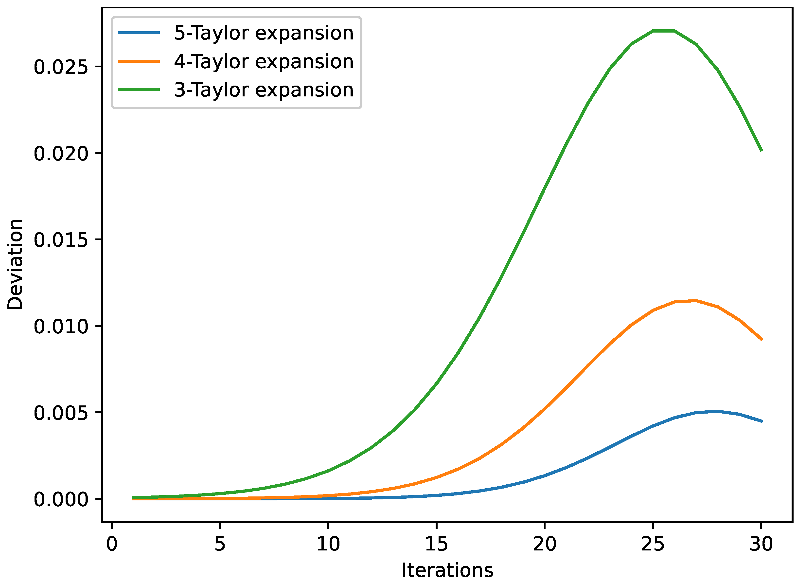
3.1.5. Complex Function Design

Intelligent optimization algorithms often involve complex function computations, such as exponential, trigonometric, logarithmic, etc. When designing hardware for complex function computations, the Taylor series expansion can transform complex operations into base arithmetic operations.

3.2. General Hardware Design Flow for Hybrid Intelligent Optimization Algorithm Based on Multi-FPGA

This section presents a general hardware implementation process for hybrid intelligent optimization algorithms based on multi-FPGA. The implementation process is divided into five steps: designing H-IOA, decomposing the H-IOA, selecting the implemented method, storing the population, and testing optimization. The following is a detailed introduction.

3.2.1. Designing Hybrid Algorithms

The hybridization of intelligent optimization algorithms refers to combining two or more optimization algorithm techniques to create novel algorithms which offer improved performance or address specific problems. The specific implementation of hybridization strategies depends on the type of algorithm used and the characteristics of the problem domain. The specific strategies for hybridization can be classified as exploration-based hybridization, exploitation-based hybridization, and adaptation-based hybridization. The hybridization of algorithms should be based on the characteristics of different intelligent optimization algorithms.

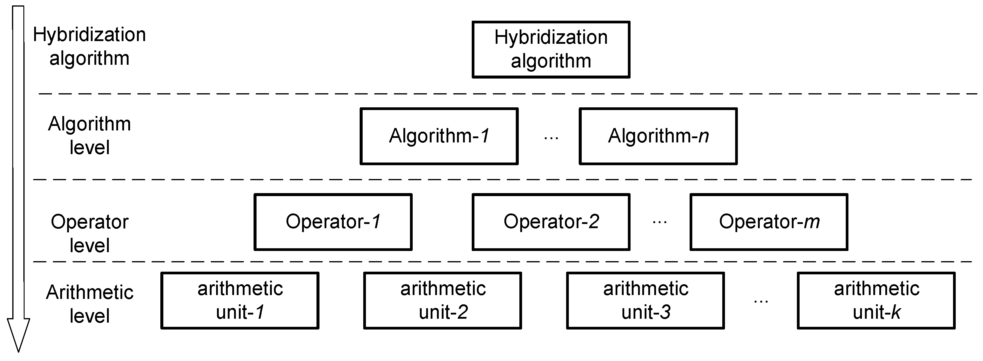
3.2.2. Decomposing Hybrid Algorithm

To design an algorithm based on FPGA, the first step is to analyze the structure of the algorithm. Next, the algorithm is decomposed into multiple sub-modules in a top-down method, and the sub-modules are recursively partitioned until the level of fundamental arithmetic units. Each sub-block is responsible for implementing a specific functionality of the algorithm. As shown in Figure 3, generally, hybrid algorithms can be decomposed into four levels: the hybridization algorithm level, the algorithm level, the operator level, and the arithmetic level. Finally, the ports, data inputs, data processing, and data outputs of each sub-module need to be determined.
The solving process of intelligent optimization algorithms involves a continuous population evolution to reach the optimal position. Based on the proposed platform, the population is split into q sub-populations for evolution, where q is the number of FPGAs, and the optimization problem is divided into multiple sub-problems. Then, each sub-population is distributed to each FPGA, and each sub-population completes evolution. Finally, the optimal solutions of the sub-populations are merged into the global optimal solution, completing the solving process. Multiple operator modules are instantiated within each FPGA to support multi-individual parallelism. Based on the proposed platform, multiple sub-populations are evolved in parallel, and individuals within each sub-population are also executed in parallel. Therefore, the execution efficiency of the algorithm is significantly improved, resulting in higher computing performance.
In addition, there are complex parameter calculations for intelligent optimization algorithms. These parameters may be computed as single-precision floating-point numbers, arithmetic inclusion e x , trigonometric function, logarithm operation, etc. A single FPGA can handle complex calculations to share the computational load of other FPGAs.

3.2.3. Selecting Implementation Methods

After the algorithm is decomposed, designing each module is crucial. Modules typically have multiple implementation methods available, each with different outcomes and effects. Different implementation methods can lead to different execution speeds, the precision of computation results, and the utilization of FPGA logic resources. For example, floating-point arithmetic has high precision but is slower and requires more resource utilization, while fixed-point arithmetic is faster and more resource-efficient but has lower precision. To effectively meet design goals, developers should select the implementation method flexibly based on demand and balance the trade-off between time, space, and precision requirements.
To design modules based on FPGA, developers should first identify key modules with the following characteristics: compute-intensive, high utilization of logic resources, high data throughput, frequent communication, and strong reusability. The key modules should be carefully designed and optimized for performance.
In a multi-FPGA environment, better-performance FPGAs can implement critical modules. In addition, the interface of each module should be designed according to the communication protocol to improve the efficiency of board-level communication. By optimizing the design of each module and interface, the overall system performance can be significantly improved.

3.2.4. Designing Low-Layer Modules

The sub-modules should be designed based on the functional requirements of each sub-block. These modules may include simple logic gates, memory blocks, or more complex functional blocks such as arithmetic, signal processing, or decision-making units. To achieve efficient cooperation between operators of different IOAs, some operator modules may be modified in data format, data flow, processing steps, and other aspects. By optimizing the operator modules, the algorithm can effectively leverage the strengths of different optimization techniques and achieve better performance.
Parallel design is essential to design sub-modules efficiently, such as multi-individual and multi-dimensional parallelism. Calling the sub-module in duplicate or parallel can significantly improve the performance of the algorithm. By optimizing the parallel design of the sub-module, the algorithm can achieve better performance and efficiency.

3.2.5. Integrate Low-Layer Modules

After the sub-module is designed, the sub-module must be integrated. The modules are integrated to create a complete FPGA implementation of the algorithm, which involves developing the interconnections between the modules and ensuring that the data flow is correct.
In a multi-FPGA environment, board-level communication needs to be considered, and custom high-speed interfaces may be required to minimize latency and maximize bandwidth.

3.2.6. Testing and Optimization

The implementation on the FPGA should be tested and any issues debugged, which may involve adjusting the design or optimizing the code to improve performance or reduce resource usage.
Regarding optimization design, the primary considerations are reducing resource occupation, improving execution speed, and improving fault tolerance. Here are some standard optimization methods: reuse modules to reduce logical resource usage; optimize storage to save logical resources and improve access flexibility; load balancing for multiple chips. The modules on the single FPGA are as independent as possible to reduce the amount of data for board-level communication.
In general, designing a circuit for a hybrid intelligent optimization algorithm on a multi-FPGA system requires careful consideration of the system architecture, the partitioning of the algorithm, and the integration of the modules. With proper design and implementation, a multi-FPGA system can offer significant performance improvements over a single FPGA system.

4. A Case Study of Hardware Design for a Hybrid Intelligent Optimization Algorithm Based on the Multi-FPGA Platform

This section provides a detailed presentation of the hardware design instance for a hybrid algorithm containing GA, PIO, and SA. The hardware design of the algorithm is applied to the FJSP problem.
This work selects the hybrid algorithm of PIO, GA, and SA for hardware design, mainly considering the following advantages: PIO has a robust search ability; GA is suitable for solving discrete optimization problems; SA can balance the explore and exploit phases. This section first gives a brief introduction to the hybrid algorithms. Then, it gives the concrete hardware design.

4.1. Basic PIO

By imitating homing pigeons, Duan proposes the pigeon-inspired optimization algorithm [30]. Magnetic fields and landmarks are used by pigeons to identify paths during homing. Thus, two operators are proposed: the map and compass operator and the landmark operator.

4.1.1. Map and Compass Operator

Pigeons can perceive the geomagnetic field using magnetic objects and can form a cognitive map. Pigeons use the height of the sun as a compass to adjust flight direction, and the reliance on the sun and magnetic objects decreases as when approaching the destination.

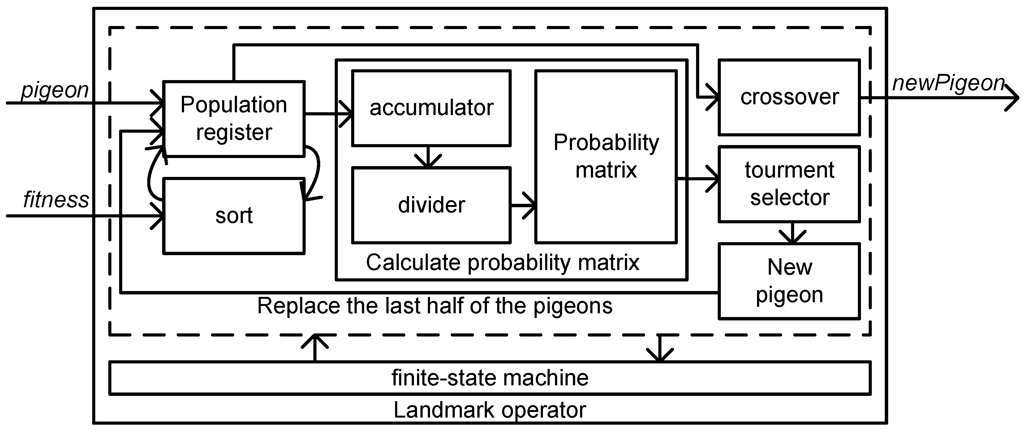
4.1.2. Landmark Operator

The landmark operator is employed to simulate the influence of landmarks on pigeons in navigation. As pigeons approach the destination, nearby landmarks are relied on more. If the pigeons are familiar with the landmarks, the pigeons fly directly to the destination. Otherwise, the pigeons follow the flight of pigeons familiar with the landmarks.

4.1.3. Mathematical Model

Assuming the search space is n-dimensional, the i-th pigeon can be mathematically represented by an n-dimensional vector X i = ( x i , 1 , x i , 2 , , x i , n ) . Similarly, the velocity of each pigeon, which reflects pigeons positional changes, can be expressed as another n-dimensional vector, V i = ( v i , 1 , v i , 2 , , v i , n ) . The best global position, obtained by comparing the positions of all pigeons after each iteration, can be denoted by X g = ( x g , 1 , x g , 2 , , x g , n ) . Then, each pigeon updates the velocity and position according to the following two equations.
V i ( t ) = V i ( t 1 ) e R t + r a n d ( X g X i ( t 1 ) )
X i ( t ) = X i ( t 1 ) + V i ( t )
where t represents the current number of iterations. R is the map and compass factor, with a range of [0, 1) which controls the influence of the latest velocity on the current velocity. Lastly, rand is a random number uniformly distributed in the range [0, 1). Equation (1) updates the pigeon’s velocity according to the pigeon’s latest velocity and the distance between the pigeon’s current position and the best global position. The pigeon then updates the position using a new velocity according to Equation (2). Once the required number of iterations is reached, the map and compass operator stops working, and the landmark operator continues to operate.
In the landmark operator, pigeons rely on landmarks for navigation. After each iteration, the number of pigeons decreases by half according to Equation (3). Pigeons far from the destination are unfamiliar with the landmarks and cannot discern the path, so such pigeons are discarded. X c represents the center position of the remaining pigeons, which serves as a landmark and reference for flight. The equation used in the landmark operator is as follows.
N p ( t ) = N p ( t 1 ) 2
X c ( t ) = n = 1 N p ( t ) X i ( t ) f i t n e s s ( X i ( t ) ) N p n = 1 N p ( t ) f i t n e s s ( X i ( t ) )
X i ( t ) = X i ( t 1 ) + r a n d ( X c ( t ) X i ( t 1 ) )
where N p is the size of the population; f i t n e s s is an evaluation function calculating the fitness of each pigeon. Equation (4) is used to calculate the center value of the remaining pigeons, and then each pigeon flies towards a new position according to Equation (5). Once the required number of iterations is reached in the landmark operator, the operator stops working, and the algorithm terminates.
The flow of the algorithm is as follows.
Step 1:Initialize the parameters, including the size of the pigeon swarm N, the map and compass factor R, the maximum number of iterations N1 for the map and compass operator, and the maximum number of iterations N2 for the landmark operator.
Step 2: Randomly generate N pigeons, evaluate each individual, and determine the best pigeon X g .
Step 3: Perform the map and compass operator by updating each pigeon’s velocity and position, evaluating the fitness of all pigeons and determining the best pigeon X g .
Step 4: Check the termination condition for the iteration; if the termination condition of the map and compass operator is met, go to Step 5. Otherwise, go to Step 3.
Step 5: Perform the landmark operator by updating each pigeon’s velocity and position, evaluating the fitness of all pigeons and determining the best pigeon X g .
Step 6: Check the termination condition for the iteration: if the termination condition of the map and compass operator is met, stop. Otherwise, go to Step 5.

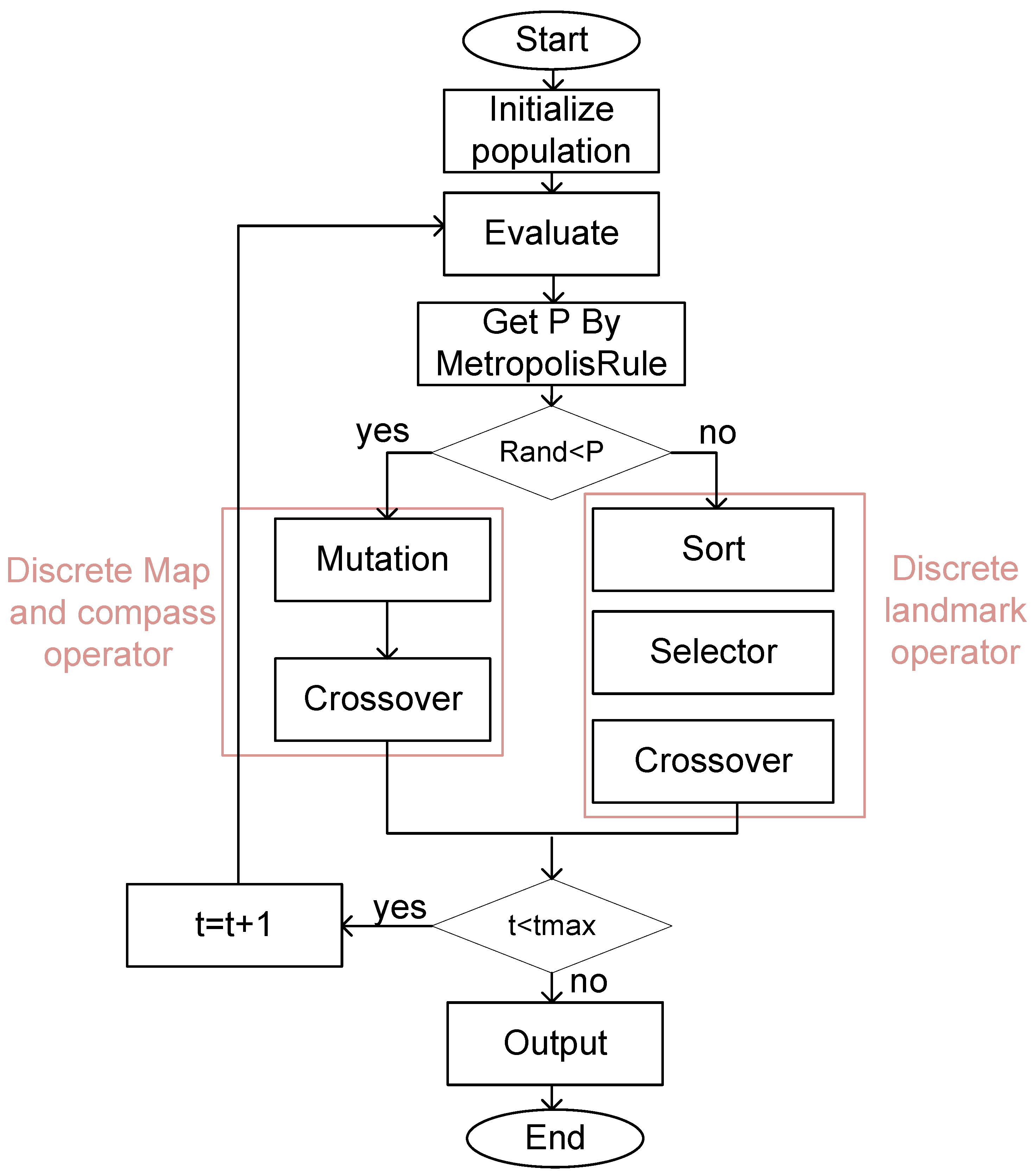
4.2. Hybrid Intelligent Optimization Algorithm for SA-PIO

Achieving a proper balance between exploration and exploitation is often the most challenging aspect of developing a metaheuristic algorithm due to the stochastic nature of the optimization process. The map and compass operator in PIO has a robust exploration but weak exploitation ability. The landmark operator is the opposite. The traditional PIO algorithm executes the map and compass operator first for iteration and then executes the landmark operator for iteration. The convergence curve is not smooth and the overall performance of the algorithm is weakened.
Simulated annealing (SA) is a metaheuristic optimization algorithm inspired by the physical annealing process in materials science. The algorithm is particularly useful for solving optimization problems where the search space is large and complex and where traditional gradient-based optimization techniques may not be effective.
SA maintains a solution candidate and iteratively modifies the solution by randomly perturbing. The algorithm then evaluates the new candidate solution and decides whether to accept or reject the new solution based on a probability function, which is determined by the current state of the system and a temperature parameter. As the algorithm progresses, the temperature gradually decreases, reducing the probability of accepting worse solutions and allowing the algorithm to converge to a high-quality solution.
The metropolis rule is a critical component of the simulated annealing (SA) algorithm, which determines whether to accept or reject a new candidate solution during optimization. The metropolis rule is based on a probability function.
The exploration and exploitation phases can be more effectively balanced by deciding which operator of the PIO algorithm can execute utilizing probabilistic selection rather than simply sequential execution. The hybridization of SA and PIO (SA-PIO) is adaptive. The details are as follows:
In SA-PIO, the decision to use the map and compass operator or the landmark operator is made with a probability P in Equation (6). Before each iteration, a random number R a n d o m is generated first, and then the r a n d o m and P are compared to determine which operator to execute. Figure 4 refers to PIO and MR-PIO implementation results, where the basic PIO parameter is set to R = 0.2 ,   N 1 = 15 ,   N 2 = 15 , population size = 10, dimension = 10; the SA-PIO parameter is set to a = 0.9 ,   w = 5 .
P = e x p ( 1 a t × w )

4.3. Hybrid Intelligent Optimization Algorithm for SA-GA-PIO

The solving ability of the PIO algorithm is powerful in continuous space but weak in a discrete space. Improving the algorithm discretization is necessary to enable the PIO algorithm to solve combinatorial optimization problems in discrete space.
In this work, the genetic algorithm is used to hybridize the PIO algorithm and improve the solving ability in a discrete space. Specifically, the operator of the PIO algorithm is discretized.

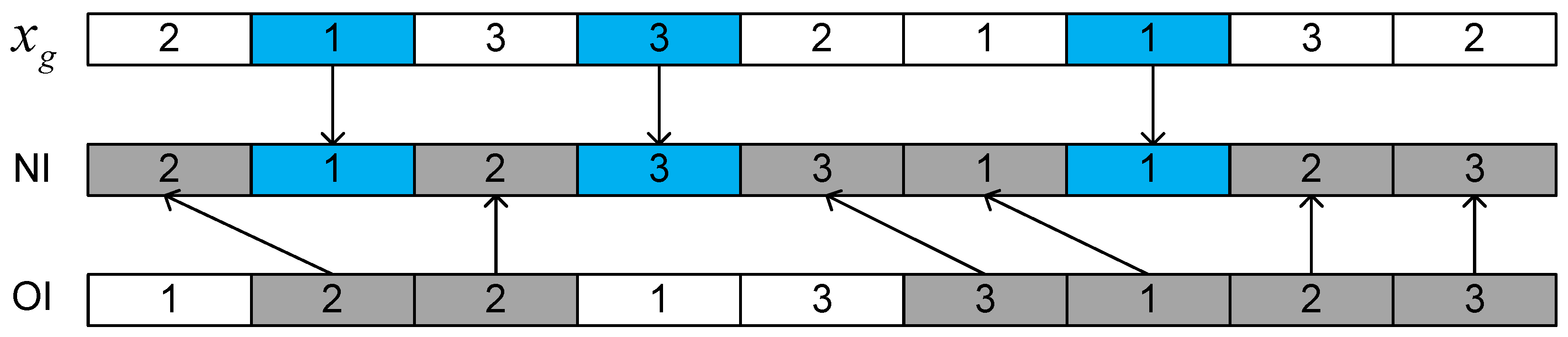
4.3.1. The Discrete Map and Compass Operator

According to Equations (1) and (2), the new positions in the map and compass operator are determined by the velocity and the position of the best pigeon. The mutation and crossover operators in the genetic algorithm are used to discretize the map and the compass operator as in Equation (7):
X i ( t ) = c ( m ( x i ( t 1 ) ) , X g )
where m ( ) is the mutation operator in GA, the detail is shown in Figure 5. The mutation operation is used as the implementation method, representing the impact of velocity on the flight of pigeon i. In Figure 5, OI is the original position of pigeon i, and NI is the new position of pigeon i. First, two points are randomly selected in the OI. Then, the elements are swapped in the selected positions to generate the NI.
And c ( ) is the crossover operator in GA and the detail is shown in Figure 6. The crossover operation is used as the implementation method, representing the impact of the best position of all pigeons on the flight of pigeon i. Additionally, pigeon convergence is ensured by crossing with the best pigeons. The specific workflow of the operator is as follows.
Step 1: Generate some positions randomly in the OI.
Step 2: Replace the elements in the selected positions of OI with the corresponding elements in the selected positions of X g .
Step 3: Remove the elements in OI which were replaced with the corresponding elements from X g .
Step 4: Starting from the first position, fill in the remaining selected positions in the OI with the appropriate elements.

4.3.2. The Discrete Landmark Operator

Similar to the map and compass operator, the landmark operator must also be discretized. The discrete map and compass operator can be described as follows.
In the basic PIO algorithm, half of the pigeon swarm is removed using the landmark operator to maintain the overall superiority of the pigeon swarm. Therefore, the size of the initial pigeon swarm directly affects the number of iterations of the landmark operator. The knowledge-based pigeon swarm updating strategy using the probability model is proposed. The core idea is to learn the probability matrix from the top 50% of the best individuals and to generate new pigeons according to the probability matrix to replace half of the slowest-flying pigeons. Therefore, the overall superiority of the pigeon swarm is maintained while also avoiding the impact of the initial swarm size on the number of iterations of the landmark operator. The details are as follows.
Step 1: All the pigeons are sorted according to fitness.
Step 2: Using the highest 50% individuals as samples, the probability matrix is generated by calculating the probability which each operation occurs at each position.
Step 3: New individuals are generated using tournament selection until the next 50% of pigeons are replaced.
Step 4: All pigeons are crossed with the best pigeons.
Overall, based on PIO, SA is hybridized to balance the exploration and exploitation stages, and GA is hybridized to solve discrete combinatorial optimization problems. The flow of the hybridization algorithm is shown in Figure 7.

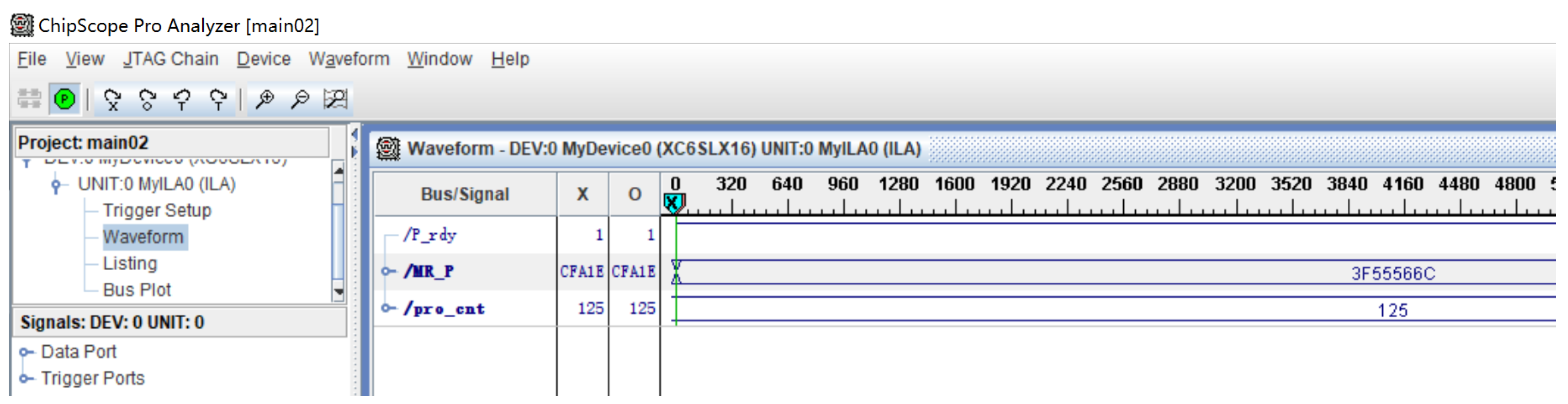
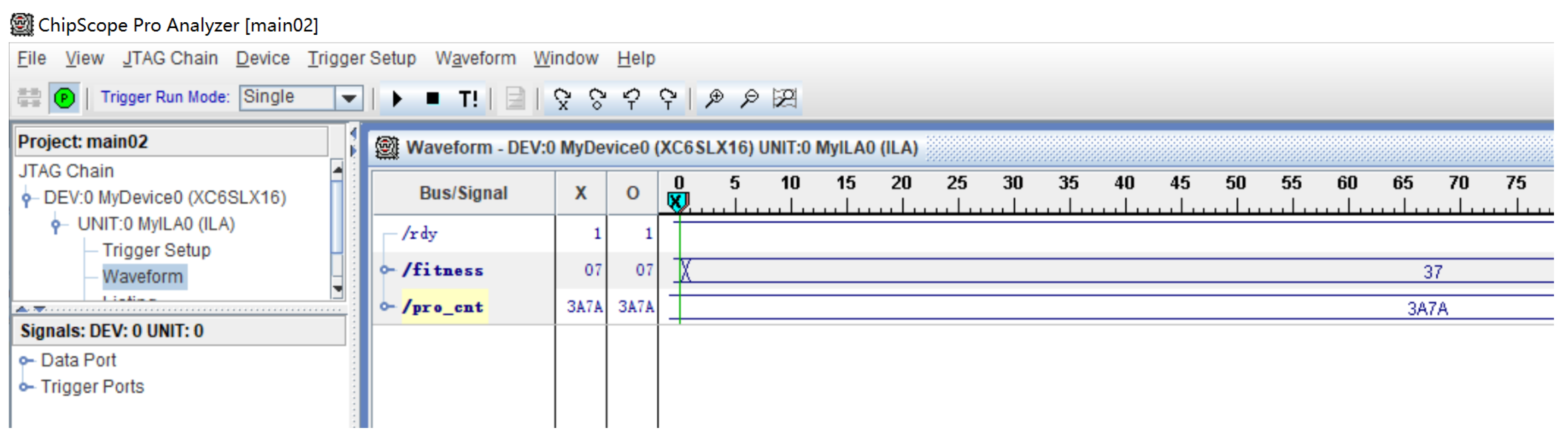
4.4. Case for Hardware Design of SA-GA-PIO Based on Multi-FPGA

The case for the hardware design of SA-GA-PIO based on multi-FPGA is introduced as follows. This paper presents the case according to the process mentioned above in Section 3. First, the hardware platform used in this work is shown in Figure 8. Three boards are used; the bottom layer is the base board, which is used to power the upper board and communicate outside. The middle layer is the leader board with an FPGA chip, where the hardware program is used to control the execution of the entire algorithm. The top layer is the follower board with an FPGA chip, in which the key modules is performed.
After the algorithm is hybridized, the hybridization algorithm needs to be split by the top-down method. According to the two step of general hardware design flow, this work splits the algorithm as shown in the Figure 9. The hybridization algorithm is divided into four layers, which are the hybridization algorithm layer, the algorithm layer, the operator layer, and the arithmetic operation layer. The algorithm layer contains three algorithms, which are also the three intelligent optimization algorithms used in this case. The operator layer is the operators within each algorithm, as well as some operators assisting with the computing such as the sort operator, random generator, trigonometric function, etc. The arithmetic operation layer is the basic operation required by each operator.
Because different implementation methods lead to different execution speeds, accuracy, resource occupation, and so on, the implementation method needs to be selected before designing the sub-module. This is especially so for the implementation of key sub-modules. In this work, since the metropolis rule operator is a complex function with high precision requirements and complex floating-point operations, the metropolis rule operator is the key sub-module. The operator uses single-precision floating-point numbers for computation. This work employs the Taylor series to compute the exponent to e. By comparison, the fifth-order Taylor expansion meets the accuracy requirements (see Figure 10). This work deploys the metropolis rule operator onto a single FPGA chip, which has three advantages. Firstly, the deployment of complex modules on a single FPGA facilitates load balancing on multiple FPGA platforms. Secondly, the operator has strong independence and does not require frequent communication with external devices, reducing communication overhead. Finally, the operator has strong reusability, which is often used in intelligent optimization algorithms to balance the explore and exploit phases.
To design sub-modules efficiently, making full use of the parallelism of the algorithm is necessary. The parallelism of the algorithm is first analyzed. Most intelligent optimization algorithms can perform as multi-individual and multi-dimensional in parallel as long as the individuals are independent and the dimensions within the individuals are independent. In the landmark operator, the pigeon population must be sorted according to fitness values. The parallel bubble sort algorithm is used in this work, which can effectively improve the execution speed.
According to the mathematical formula of the operator, the arithmetic logical units need to be designed. This work designs floating-point arithmetic units, fixed-point arithmetic units, logical arithmetic units, exchange operations, etc. For parallel computing, any number of arithmetic logical units can be generated to execute in parallel.
There is no controller inside the FPGA and the control unit needs to be designed. Each operator needs to use the finite state machine to control the flow of operations and schedule multiple operation units. According to the different levels of modules, multi-layer state machines can be designed to control the overall process collaboratively.
The system architecture diagram is shown in Figure 11. The leader board controls the entire algorithm process, while the follower board provides computing power to share the computing tasks of the leader board. The main modules on the leader board include the population storage module, the evaluation operator module, the discrete map and compass operator module and the discrete landmark operator module, and the activation operator module. Population storage contains information on the position and fitness of the population. The evaluation operator can assign a numerical value to each individual to evaluate the degree of superiority or inferiority of the individual in the solution space. The discrete map and compass operator and landmark operator are used for population movement. This work instantiated 10 discrete map and compass operators, so 10 individuals can move in parallel at the map and compass operators. The operator active module selects the discrete map and compass or landmark operator based on the calculated value P from the follower board and the random number generated internally. The metropolitan rule (MR) module of the simulated annealing algorithm is performed on the follower board. The calculation of the metropolitan rule is relatively complex, involving the no four fundamental arithmetic and single-precision floating-point numbers. Hardware implementation requires a significant amount of logical resources, so the MR module is deployed separately on an FPGA. The probability P from the follower board is used for the active operator. Inter-board communication uses shared storage. The follower board stores P in the BRAM. Then, the leader board sends address channel data to BRAM. The data on the data channel are sampled at the next clock.
The design of the main modules is as follows. To make the display more intuitive, the clock signal and the control signal are hidden in the figure shown below. All modules are controlled by the Finite-State Machine (FSM). All arrows indicate the flow of data. The left side of the module is the input of the module, and the right side of the module is the output of the module. First, the module design of the metropolis rule (MR) Equation (6) in the SA algorithm is introduced. The design of the module is shown in Figure 12, where a ,   i ,   w are the input parameters of Equation (6). The MR module is implemented on the follower board, and the result P is stored in memory for the leader board to read. The design of the e x module is shown in Figure 13. The e x module uses a fifth order Taylor expansion to approximate the e x value and uses the built-in IP core of Xilinx FPGA to perform arithmetic operations on single precision floating-point numbers. The hardware design is applied to FJSP, and the evaluation module design is shown in Figure 14. The module uses a register matrix to store the execution time of each job operation on different machines. The module utilizes a state register to indicate whether the machine or the job is available. The counter calculates the working time, while the state machine controls the entire process. The input to the evaluation module is a pigeon and the output is the fitness value of the individual. The fitness value refers to the makespan, which is the completing time for a scheduling solution. The discretized map and compass operator module is designed as shown in Figure 15. The discretized map and compass operator module mainly contains a mutation and crossover operator. The current pigeon performs mutation and crossover operators to achieve the goal of optimal pigeon flight. The mutation operator swaps two random dimensions of the pigeon itself, as shown in Figure 5. The crossover operator swaps two random dimensions between the current pigeon and the optimal pigeon, as shown in Figure 6. The parallel bubble sorting module (see Figure 16) instantiates multiple swappers internally and compares and swaps multiple pairs of pigeons parallelly based on their fitness values, effectively improving the execution speed. The landmark operator module (see Figure 17) selects better individuals from the previous generation and passes better individuals on to the next generation. Firstly, the population is sorted according to the fitnesses, and then a probability matrix is calculated from the better half of the pigeons. Based on the probability matrix, the tournament selection method is used to select excellent individuals to replace the poor half of the individuals.
After designing each sub-module, the next step is integrating sub-modules in a bottom-up approach. The integration combines each algorithm function’s sub-modules, starting from the lowest level and working upward. The interconnection between modules must be designed to ensure the data flow is correct. In this work, two FPGAs are being used. Therefore, inter-board communication is important while connecting the sub-modules. This work uses shared memory to communicate between boards; specifically, after the follower board calculates P, the P is stored in BRAM, and another board reads BRAM.

4.5. Apply the Hardware Design to FJSP

The hardware design of the hybridization algorithm is applied to the FJSP, proving the potential of the design in industry. Production scheduling plays a crucial role in manufacturing systems. A well-designed scheduling solution can significantly enhance production efficiency and reduce relevant costs.
The Job-Shop Scheduling Problem (JSSP) is a typical combinatorial optimization problem, while FJSP is an extension of JSSP. FJSP with more than two jobs is a strongly nondeterministic NP-Hard (nondeterministic polynomial time) problem [31]. Finding an optimal solution in a reasonable time is often challenging.

4.5.1. Problem Formulation

Table 2 shows the variables required for problem formulation.

4.5.2. Assumption

  • The jobs are independent, and job preemption is not allowed. Additionally, each machine can process only one job at a time.
  • Each job has a predefined operation precedence.
  • All jobs and machines are available from the beginning.
  • After a job is processed on a machine, the job is immediately delivered to the next machine. The delivery time is negligible.
  • The setup time for an operation is independent of the operation sequence and is included in the processing time.

4.5.3. Mathematical Model
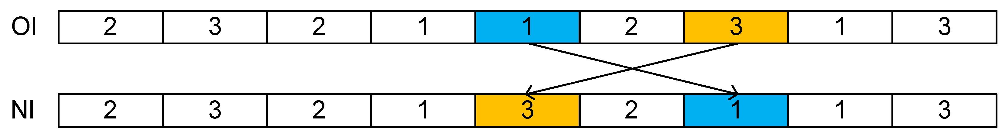
Assuming the number of job is n, j = 1 , 2 , , n , and the number of machine is m, k = 1 , 2 , , m . Each work operation must comply with the required sequence. The operation O i j can be processed on any available machine. P i j k is the processing time of operation O i j on machine k. The FJSP is solved by determining the machine selection and operation sequence for each operation on each machine.
The scheduling objective is to minimize the makespan, which refers to the maximum completion time of all operations.
m i n C m a x = m i n ( m a x ( C i j ) )
s.t.
C i j C ( i 1 ) j p i j k X i j k , i = 2 , 3 , n j
( C i j C h g p i j k ) X h g k X i j k ( Y h g i j 2 ) ( Y h g i j 1 ) + ( C h g C i j p h g k ) X h g k X i j k ( Y h g i j 2 ) ( Y h g i j + 1 ) 0
X i j k = 1 , k S i j , i , j
X i j k { 0 , 1 }
Y h g i j { 1 , 0 , 1 }
Equation (8) represents the optimization goal of the FJSP problem. Equation (9) represents the priority relationship of the operations. Equation (10) represents a machine which cannot process more than one task at the same time. Equation (11) represents an operation which can only be processed by one available machine. Equations (12) and (13) define the range of decision variables.

4.5.4. Encode

To apply intelligent optimization algorithms to solve optimization problems, the first step is to encode which maps specific problems to populations. Wu et al. [32] propose operation-based encoding to encode the FJSP problem as a row vector. Each pigeon is composed of n × m a x { n j } elements, and each element represents an operation; the same elements represent different operations of the same job in order of precedence (see Figure 18). After encoding, each pigeon represents a solution to the FJSP.

4.5.5. Decoding

The encoding method described in this paper does not assign specific machines to each operation. So, an assignment algorithm needs to be chosen to assign the operation to an idle machine. This work adopts the idle time first rule (ITFR) algorithm to assign jobs to machines. The ITFR refers to the principle which if an operation can be assigned to an idle time slot while satisfying the precedence relation, the idle time slot is given priority. If an operation cannot be assigned to an idle time slot, the operation is appended to the end of the current sequence.

5. Results and Analysis

This section presents the implementations of the SA-GA-PIO algorithm mentioned, including software and hardware. The results achieved through software and hardware implementation are then presented, and a comparison and analysis are performed.
The running of the hardware platform is shown in Figure 19. The USB interface of the multi-FPGA system is used for power supply and serial port communication. This Xilinx JTAG Programming Cable USB is used to configure and debug FPGA. The serial port debugging assistant sends instructions and receives data to multiple FPGA systems. Xilinx Chipscope is an online debugging software that comes with ISE14.7 software. Xilinx Chipscope’s function is similar to that of a logic analyzer. During debugging, the signal to be captured will be stored in the BRAM inside the FPGA. By setting the triggering conditions, the waveform of the signal to be captured will be displayed in the software. It is worth noting that the waveform of this debugging is captured in real data rather than simulation data.
The hardware implementation uses VHDL coding and is implemented on two FPGAs. The FPGA model is spartan6 xc6slx16, and the clock frequency is 100 MHz. The EDA tool used in this work is Xilinx ISE14.7. After completing the hardware design, the bitstream file is configured into the FPGA via Xilinx JTAG Programming Cable USB. The initialization of the population on the leader board is completed through the ‘.coe’ file. After configuring two FPGAs in sequence, instructions are sent through the UART Debugging assistant to start the evolution of the population. The hardware program execution signals are captured in the Xilinx chipscope. The resource utilization of the hardware implementation is obtained through the summary report from ISE14.7 after synthesis. The performance time of the hardware programs is calculated through counters within the program and obtained via capturing counter data through Xilinx Chipscope.
The software implementation uses the python language to implement the same program, and is executed on a PC with CPU model AMD Ryzen 7 5800U (Santa Clara, CA, USA), where the Python version is 3.12.4.
The parameter selection for the algorithm is as follows: the population size is 10, the dimension is 4, and the number of iterations is 30. In the simulated annealing algorithm, the parameters for the metropolis rule are a = 0.9 and w = 5 . In the simulated annealing algorithm, the operands are single-precision floating-point numbers. The value of P decreases from 0.89 to 0. The encoding method used is shown in Figure 18. In order to demonstrate the effectiveness of the proposed method, SFJS01 instances [33] were selected as benchmark instances for the FJSP problem. The execution results of software and hardware can reach the optimal value of 55, but the execution situation is significantly different. The cost time of hardware implementation is 149,700 ns, and the software implementation is 2,006,940 ns. The result proves that the hardware design is effective. Below is a detailed introduction.
This work only uses BRAM for shared memory and other functions are implemented using VHDL. Due to the deployment of complex calculations on a single follower board, even without DSP, logical resources are sufficient for implementation. Figure 20 and Figure 21 show the resource utilization of two FPGA chips. The resource utilization ratio of the two chips is roughly the same, so the load balancing can be achieved effectively according to the proposed method. There are 9112 LUTs in XC6SLx16, so the resources of both chips are 45% occupied. All designs deploying on a single FPGA are challenging due to occupying resources on single FPGA over 90%, proving a multi-FPGA solution’s effectiveness.
Figure 22 shows the performance result and the time of the follower board, where P _ r d y represents completing computing, M R _ P represents result P as single-precise float point, the p r o _ c n t is the counter for the execution times. In Figure 23, the f i t n e s s is hexadecimal 37, converted to decimal is 55. The p r o _ c n t represents the execution time, whose hexadecimal value 3 A 7 A converted to decimal is 14,970. The multi-FPGA system uses a clock frequency of 100 MHz, 10 ns per clock. Therefore, the execution time of the system is 149,700 ns. The execution time of a python program is calculated using the “time.perf counter()” function. The software program’s execution time is 2,006,940 ns. So, hardware implementation is 13.4 times faster than the software.
Table 3 shows the resource utilization of each module in multi-FPGA, as well as the execution time of the software and hardware. Overall, FPGA programs are significantly faster than software implementations. From the results, the MR module is a critical module which conforms to several characteristics: complex computation, occupying more logical resources, low communication overhead, and strong module reusability. The metropolitan rule module primarily uses single-precision floating-point numbers involving complex calculations. The MR module occupies almost half of the chip’s resources. The MR module only needs to communicate once in each iteration, resulting in low communication overhead. Intelligent optimization algorithms often have a contradiction: the balance problem between exploration and exploitation. In the early stage of searching for the optimal solution, the population should spread throughout the solution space as much as possible to avoid local optima, named the exploration stage. In the later stage of searching for the optimal solution, the population needs to gather towards the goal of having a high fitness value to converge to the optimal solution, named the exploitation stage. With more exploration, the convergence speed is slow. With more exploitation, the result may fall into local optima. Therefore, in many cases, the metropolitan rule can be widely used because the MR module can alleviate the balance contradiction between the two. Separating the MR module separately is also beneficial for module reuse. Therefore, the MR module, as a critical module in a multi-chip platform, can be deployed separately on a single chip. A Taylor expansion calculates the E X module as an operator in the metropolitan rule, and the precision obtained is shown in Figure 10. In the evaluation module, various states are stored in registers, including the machine, working, and process state registers. The machine’s running time is calculated using counters and arithmetic operations, contributing to the overall running time, i.e., the fitness value. The map and compass operator uses many registers to memorize temporary pigeons. The sort operator has significantly high execution efficiency, and the more sorted the number, the more significant the acceleration effect. The landmark operator has high execution efficiency, using many registers to memorize index and temporary pigeons.

6. Conclusions

This paper aims to address the issue of insufficient real-time performance in intelligent optimization algorithms and to investigate the implementation of hybrid algorithms on multi-FPGA platforms. This paper proposes a general hardware platform based on multi-FPGA and analyzes the characteristics of the platform and the advantages of implementing hybrid algorithms. In addition, this paper summarizes the general process of hardware design for hybrid algorithms on the platform. To demonstrate the effectiveness of the proposed method, a case study of hardware design for the SA-GA-PIO hybrid algorithm on the hardware platform is presented. Finally, the hardware design is applied to the FJSP solution to demonstrate the effectiveness of the proposed method in industry. The main work can be divided into four aspects.
Firstly, this paper presents a universal hardware platform based on multi-FPGA. The platform operates in a leader–follower mode, where the leader chip controls the overall workflow and performs simple calculations, while the follower chip is responsible for more complex computations. The scalable platform allows multiple boards to be stacked together via an interface to solve more complex optimization problems. Several methods for inter-board communication and population storage are proposed, enabling users to choose storage and communication methods flexibly according to the problems. In general, this platform is designed to combine the advantages of the platform with the characteristics of intelligent optimization algorithms to achieve a more efficient hardware design.
Secondly, this paper proposes a general design process for hybrid intelligent optimization algorithms on multi-chip platforms. In order to implement the hybrid algorithm on FPGA, a top-down splitting hybrid algorithm method is introduced. Due to the different impact of different implementation methods on the results, the selected implementation method is proposed. Then, the parallel design of sub-modules is introduced. The sub-modules are then integrated to complete the algorithm function, and the analysis of the inter-board communication is introduced.
Thirdly, a case study is designed to provide a more detailed explanation of the platform and process. The case study involves the hardware design of a hybrid algorithm SA-GA-PIO on two FPGAs. The results of the case indicate that the hardware implementation is 13.4 times faster than the software, which illustrates that the proposed approach effectively improves the real-time performance of H-IOA.
Finally, this work applies the case study design to the flexible job-shop problem (FJSP) and demonstrates the potential of the approach in industrial applications.

Author Contributions

Conceptualization, Y.Z.; Methodology, Y.Z.; Software, Y.Z.; Validation, Y.Z.; Writing—original draft, Y.Z.; Project administration, C.Z. and L.Z. All authors have read and agreed to the published version of the manuscript.

Funding

This research was funded by National Science and Technology Major Project from Minister of Science and Technology, China, grant number 2018AAA0103100.

Data Availability Statement

Data are contained within the article.

Conflicts of Interest

The authors declare no conflicts of interest.

References

  1. Altay, E.V.; Alatas, B. Intelligent optimization algorithms for the problem of mining numerical association rules. Phys. A Stat. Mech. Its Appl. 2020, 540, 123142. [Google Scholar] [CrossRef]
  2. Cheng, M.Y.; Prayogo, D. Symbiotic organisms search: A new metaheuristic optimization algorithm. Comput. Struct. 2014, 139, 98–112. [Google Scholar] [CrossRef]
  3. Bayraktar, Z.; Komurcu, M.; Werner, D. Wind Driven Optimization (WDO): A novel nature-inspired optimization algorithm and its application to electromagnetics. In Proceedings of the 2010 IEEE Antennas Propagation Society International Symposium, Toronto, ON, Canada, 11–17 July 2010; pp. 1–4. [Google Scholar]
  4. Zhang, X.; Wang, Y.; Cui, G.; Niu, Y.; Xu, J. Application of a novel IWO to the design of encoding sequences for DNA computing. Comput. Math. Appl. 2009, 57, 2001–2008. [Google Scholar] [CrossRef]
  5. Katoch, S.; Chauhan, S.S.; Kumar, V. A review on genetic algorithm: Past, present, and future. Multimed. Tools Appl. 2021, 80, 8091–8126. [Google Scholar] [CrossRef] [PubMed]
  6. Marini, F.; Walczak, B. Particle swarm optimization (PSO). A tutorial. Chemom. Intell. Lab. Syst. 2015, 149, 153–165. [Google Scholar] [CrossRef]
  7. Stützle, T.; Dorigo, M. ACO algorithms for the traveling salesman problem. Evol. Algorithms Eng. Comput. Sci. 1999, 4, 163–183. [Google Scholar]
  8. Rutenbar, R.A. Simulated annealing algorithms: An overview. IEEE Circuits Devices Mag. 1989, 5, 19–26. [Google Scholar] [CrossRef]
  9. Hao, R.; Luo, D.; Duan, H. Multiple UAVs mission assignment based on modified pigeon-inspired optimization algorithm. In Proceedings of the 2014 IEEE Chinese Guidance, Navigation and Control Conference, Yantai, China, 8–10 August 2014; pp. 2692–2697. [Google Scholar]
  10. Chen, S.; Duan, H. Fast image matching via multi-scale Gaussian mutation pigeon-inspired optimization for low cost quadrotor. Aircr. Eng. Aerosp. Technol. 2017, 89, 777–790. [Google Scholar] [CrossRef]
  11. Duan, H.; Qiu, H.; Fan, Y. Unmanned aerial vehicle close formation cooperative control based on predatory escaping pigeon-inspired optimization. Sci. Sin. Tech. 2015, 45, 559–572. [Google Scholar]
  12. Juang, C.F. A hybrid of genetic algorithm and particle swarm optimization for recurrent network design. IEEE Trans. Syst. Man Cybern. Part B Cybern. 2004, 34, 997–1006. [Google Scholar] [CrossRef]
  13. Hu, Y.; Liu, Y.; Liu, Z. A survey on convolutional neural network accelerators: GPU, FPGA and ASIC. In Proceedings of the 2022 14th International Conference on Computer Research and Development (ICCRD), Shenzhen, China, 7–9 January 2022; pp. 100–107. [Google Scholar]
  14. Nurvitadhi, E.; Sim, J.; Sheffield, D.; Mishra, A.; Krishnan, S.; Marr, D. Accelerating recurrent neural networks in analytics servers: Comparison of FPGA, CPU, GPU, and ASIC. In Proceedings of the 2016 26th International Conference on Field Programmable Logic and Applications (FPL), Lausanne, Switzerland, 29 August–2 September 2016; pp. 1–4. [Google Scholar]
  15. Huang, H.C. FPGA-based parallel metaheuristic PSO algorithm and its application to global path planning for autonomous robot navigation. J. Intell. Robot. Syst. 2014, 76, 475–488. [Google Scholar] [CrossRef]
  16. Da Costa, A.L.; Silva, C.A.; Torquato, M.F.; Fernandes, M.A. Parallel implementation of particle swarm optimization on FPGA. IEEE Trans. Circuits Syst. II Express Briefs 2019, 66, 1875–1879. [Google Scholar] [CrossRef]
  17. Scheuermann, B.; So, K.; Guntsch, M.; Middendorf, M.; Diessel, O.; ElGindy, H.; Schmeck, H. FPGA implementation of population-based ant colony optimization. Appl. Soft Comput. 2004, 4, 303–322. [Google Scholar] [CrossRef]
  18. Messai, A.; Mellit, A.; Guessoum, A.; Kalogirou, S.A. Maximum power point tracking using a GA optimized fuzzy logic controller and its FPGA implementation. Sol. Energy 2011, 85, 265–277. [Google Scholar] [CrossRef]
  19. Allaire, F.C.; Tarbouchi, M.; Labonté, G.; Fusina, G. FPGA implementation of genetic algorithm for UAV real-time path planning. In Proceedings of the Unmanned Aircraft Systems: International Symposium on Unmanned Aerial Vehicles, UAV’08, Reno, NV, USA, 8–10 June 2009; pp. 495–510. [Google Scholar]
  20. Huang, H.C. FPGA-based hybrid GA-PSO algorithm and its application to global path planning for mobile robots. Prz. Elektrotechniczny 2012, 88, 281–284. [Google Scholar]
  21. Huang, H.C. A Taguchi-based heterogeneous parallel metaheuristic ACO-PSO and its FPGA realization to optimal polar-space locomotion control of four-wheeled redundant mobile robots. IEEE Trans. Ind. Inform. 2015, 11, 915–922. [Google Scholar] [CrossRef]
  22. Mirjalili, S.; Lewis, A. The whale optimization algorithm. Adv. Eng. Softw. 2016, 95, 51–67. [Google Scholar] [CrossRef]
  23. Shi, Y. Brain storm optimization algorithm. In Proceedings of the Advances in Swarm Intelligence: Second International Conference, ICSI 2011, Chongqing, China, 12–15 June 2011; pp. 303–309. [Google Scholar]
  24. Yang, X.S.; He, X. Firefly algorithm: Recent advances and applications. Int. J. Swarm Intell. 2013, 1, 36–50. [Google Scholar] [CrossRef]
  25. Jiang, Q.; Guo, Y.; Yang, Z.; Zhou, X. A parallel whale optimization algorithm and its implementation on FPGA. In Proceedings of the 2020 IEEE Congress on Evolutionary Computation (CEC), Glasgow, UK, 19–24 July 2020; pp. 1–8. [Google Scholar]
  26. Hassanein, A.; El-Abd, M.; Damaj, I.; Rehman, H.U. Parallel hardware implementation of the brain storm optimization algorithm using FPGAs. Microprocess. Microsyst. 2020, 74, 103005. [Google Scholar] [CrossRef]
  27. Sadeeq, H.; Abdulazeez, A.M. Hardware implementation of firefly optimization algorithm using FPGAs. In Proceedings of the 2018 International Conference on Advanced Science and Engineering (ICOASE), Duhok, Iraq, 9–11 October 2018; pp. 30–35. [Google Scholar]
  28. Biookaghazadeh, S.; Ravi, P.K.; Zhao, M. Toward multi-fpga acceleration of the neural networks. ACM J. Emerg. Technol. Comput. Syst. JETC 2021, 17, 1–23. [Google Scholar] [CrossRef]
  29. Sun, Y.; Amano, H. Fic-rnn: A multi-fpga acceleration framework for deep recurrent neural networks. IEICE Trans. Inf. Syst. 2020, 103, 2457–2462. [Google Scholar] [CrossRef]
  30. Goel, S. Pigeon optimization algorithm: A novel approach for solving optimization problems. In Proceedings of the 2014 International Conference on Data Mining and Intelligent Computing (ICDMIC), New Delhi, India, 5–6 September 2014; pp. 1–5. [Google Scholar]
  31. Brandimarte, P. Routing and scheduling in a flexible job shop by tabu search. Ann. Oper. Res. 1993, 41, 157–183. [Google Scholar] [CrossRef]
  32. Wu, X.; Wu, S. An elitist quantum-inspired evolutionary algorithm for the flexible job-shop scheduling problem. J. Intell. Manuf. 2017, 28, 1441–1457. [Google Scholar] [CrossRef]
  33. Fattahi, P.; Saidi Mehrabad, M.; Jolai, F. Mathematical modeling and heuristic approaches to flexible job shop scheduling problems. J. Intell. Manuf. 2007, 18, 331–342. [Google Scholar] [CrossRef]
Figure 1. General hardware design for H-IOA based on multi-FPGA.
Electronics 13 03504 g001
Figure 2. General parallel design for IOA.
Electronics 13 03504 g002
Figure 3. A top-down split method for H-IOA.
Electronics 13 03504 g003
Figure 4. Convergence curves of basic PIO and MR-PIO.
Electronics 13 03504 g004
Figure 5. A mutation operator example.
Electronics 13 03504 g005
Figure 6. A crossover operator example.
Electronics 13 03504 g006
Figure 7. The flow of the hybridization algorithm containing PIO, SA, and GA.
Electronics 13 03504 g007
Figure 8. The general hardware platform for hybrid algorithms based on multi-FPGA.
Electronics 13 03504 g008
Figure 9. Split for SA-GA-PIO hybrid algorithm by the top-down method.
Electronics 13 03504 g009
Figure 10. Precision of e x ; the precision of the fifth-order Taylor formula is sufficient within 30 iterations.
Electronics 13 03504 g010
Figure 11. System architecture of multi-FPGA design.
Electronics 13 03504 g011
Figure 12. Hardware design of metropolis rule module.
Electronics 13 03504 g012
Figure 13. Hardware design of e x module.
Electronics 13 03504 g013
Figure 14. Hardware design of evaluate module.
Electronics 13 03504 g014
Figure 15. Hardware design of map and compass operator module.
Electronics 13 03504 g015
Figure 16. Hardware design of parallel bubble sort module.
Electronics 13 03504 g016
Figure 17. Hardware design of landmark operator module.
Electronics 13 03504 g017
Figure 18. Encode method for FJSP.
Electronics 13 03504 g018
Figure 19. The experimental setup of this work.
Electronics 13 03504 g019
Figure 20. Follower board resource occupancy.
Electronics 13 03504 g020
Figure 21. Leader board resource occupancy.
Electronics 13 03504 g021
Figure 22. Follower board result sampling via Xilinx Chipscope.
Electronics 13 03504 g022
Figure 23. Leader board result sampling via Xilinx Chipscope.
Electronics 13 03504 g023
Table 1. Comparison of implementation methods for population storage.
Storage ModeMemory CapacityAccess SpeedFlexibility
External memoryEnormousRapidEnormous
BRAMLargeFastLarge
DRAMModerateSlowModerate
RegisterSmallGradualSmall
Table 2. The variables required for problem formulation.
VariablesDescriptions
nNumber of jobs
mNumber of machines
n j Number of the operations for job j
j , g Index for jobs, j , g = 1 , 2 , , n
i , h Index for operations, i , h = 1 , 2 , , n j
kIndex for machines, k = 1 , 2 , , m
O i j i-th operation of job j
O i j k Operation O i j is processed on machine k
P i j k Processing time of operation O i j on machine k
C m a x Makespan, the completing time for a scheduling solution
C i j Ending time of operation O i j
X i j k X i j k = 1 if the operation O i j is processed on machine k; X i j k = 0 otherwise
Y h g i j Y h g i j = 1 if operation O h g is the precedence of operation O i j
Y h g i j = 1 if operation O i j is the precedence of operation O h g ;
Y h g i j = 0 otherwise
S i j Set of available machines for operation O i j
Table 3. The result each module implemented in multi-FPGA and software.
ModuleUsed Logic (LUT-6)RegistersClock Cycles to OutputTime to Output (in ns)Time to Output in Software (in ns)
MR4105546329329303399
E x 145017062422420599
Evaluation168118323207700
Compass26683225248248010,299
Sort15251706525204710
Landmark28893345199199045,500
Disclaimer/Publisher’s Note: The statements, opinions and data contained in all publications are solely those of the individual author(s) and contributor(s) and not of MDPI and/or the editor(s). MDPI and/or the editor(s) disclaim responsibility for any injury to people or property resulting from any ideas, methods, instructions or products referred to in the content.

