


State-of-the-Art Electric Vehicle Modeling: Architectures, Control, and Regulations

 ,
,  , , ,
, , ,  , and
, and 
Abstract
:1. Introduction
2. Background
3. Energy Storage System (ESS)
3.1. Battery Energy Storage System (BESS)
3.1.1. Lithium-Ion Batteries (LIBs)
3.1.2. Nickel-Metal Hydride (NiMH) Batteries
3.1.3. ZEBRA Batteries
3.1.4. Solid-State Batteries (SSB)
3.1.5. Lead Acid Batteries (LABs)
3.1.6. Other Energy Storage Types
Supercapacitors (SCs)
Fuel Cells (FCs)
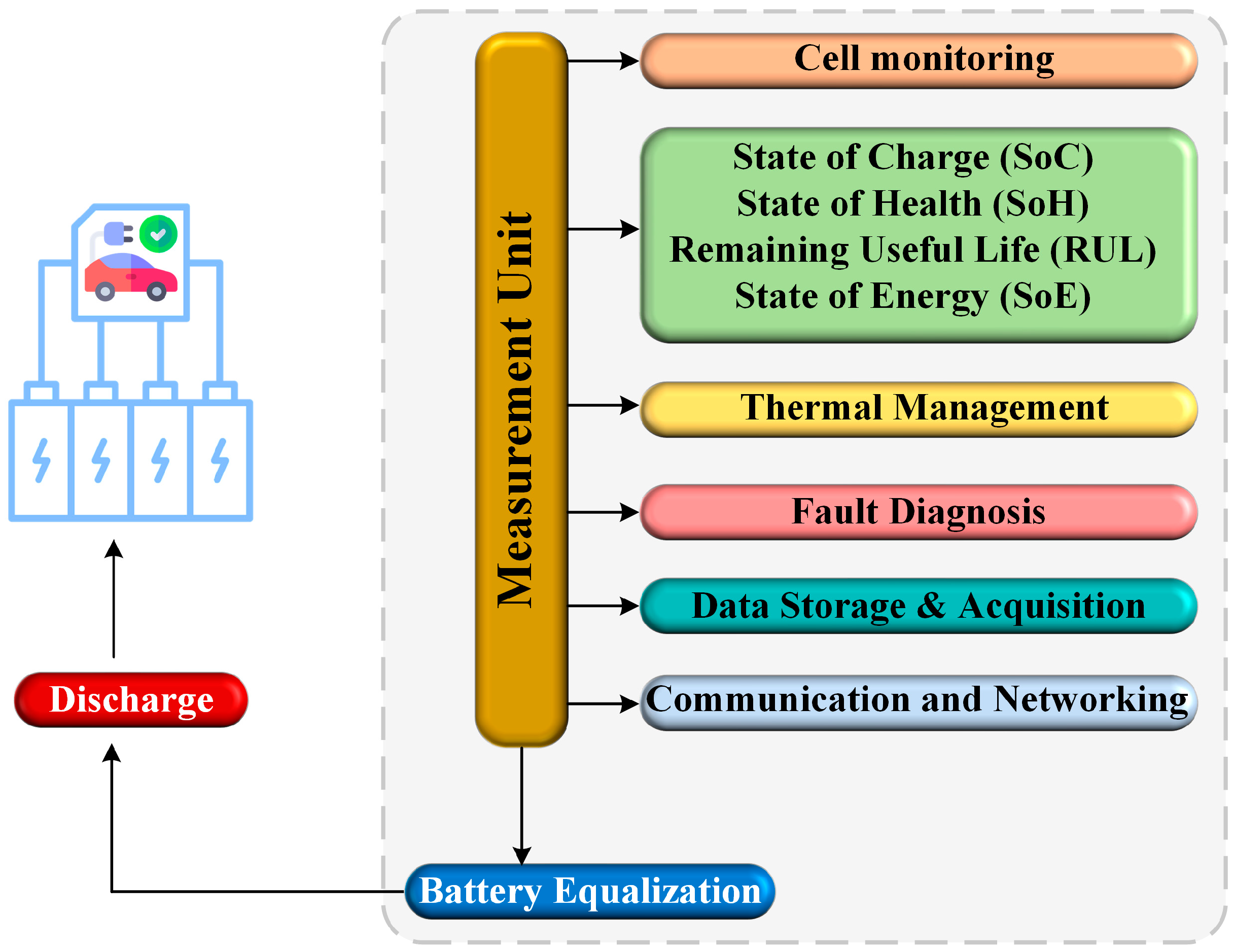
3.2. Battery Management Systems
- Measuring the status of each component of the EV, such as the battery state of charge (SoC), state of health (SoH), and voltage and current levels.
- Conducting the necessary investigation on this data to assess the battery capacity and ensure cells and battery balance.
- Predict any degradation possibilities for the BESS.
- Running the thermal checkup and regulating the BESS temperature.
- Observing any fault conditions with detection, diagnosis, and mitigation.
- Regulating the charging and discharging signals through the proper power and control management approaches.
- Supporting data exchange with other IoT devices toward enhancing data acquisition, storage, and performance optimization.
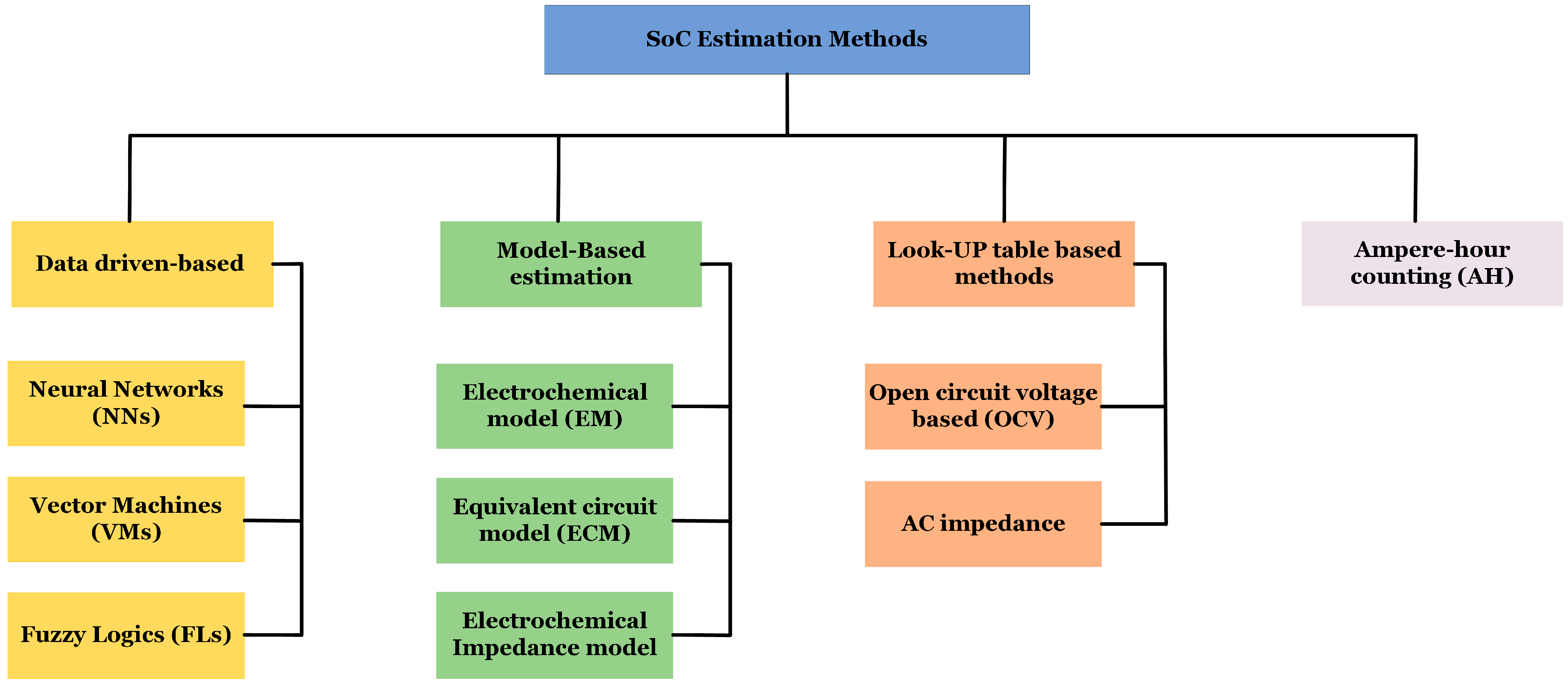
3.2.1. SOC/SOH Estimation Approaches
3.2.2. Battery Thermal Management
3.3. Technical Challenges and Future Tre Systems
4. Charging Technologies and Control
4.1. EV Charging Levels
4.2. EV Charging Methods
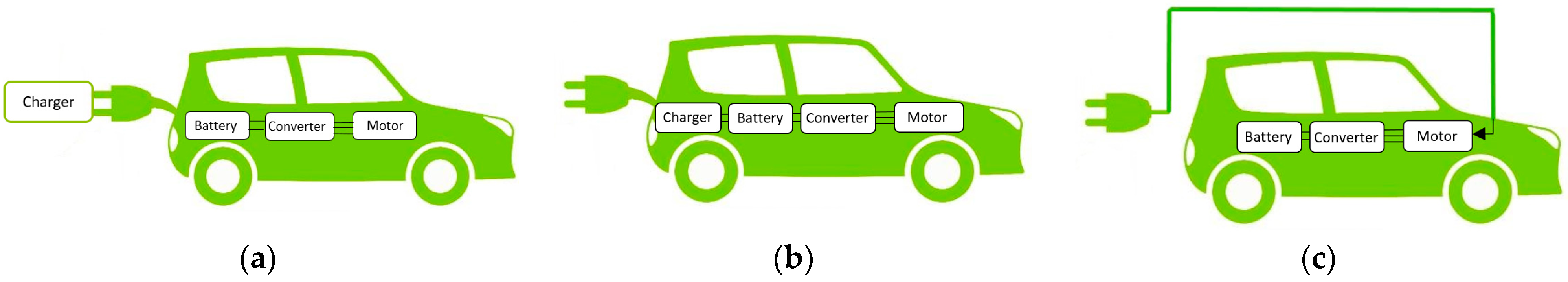
4.2.1. Conductive Chargers
Off-Board Chargers
On-Board Chargers
Integrated On-Board Battery Chargers (IOBC)
4.2.2. Wireless Chargers
Inductive Coupling Chargers
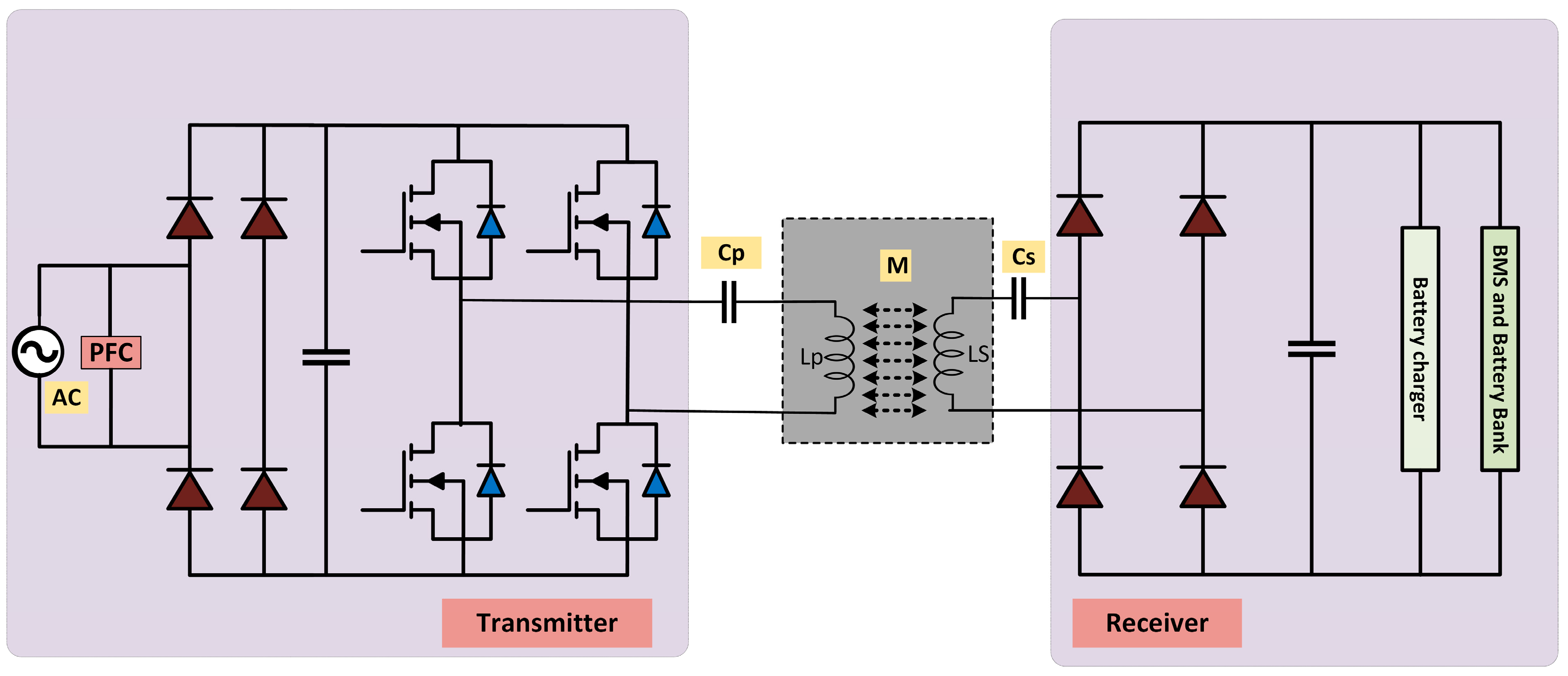
Inductive Resonant Chargers
Capacitive Wireless Chargers
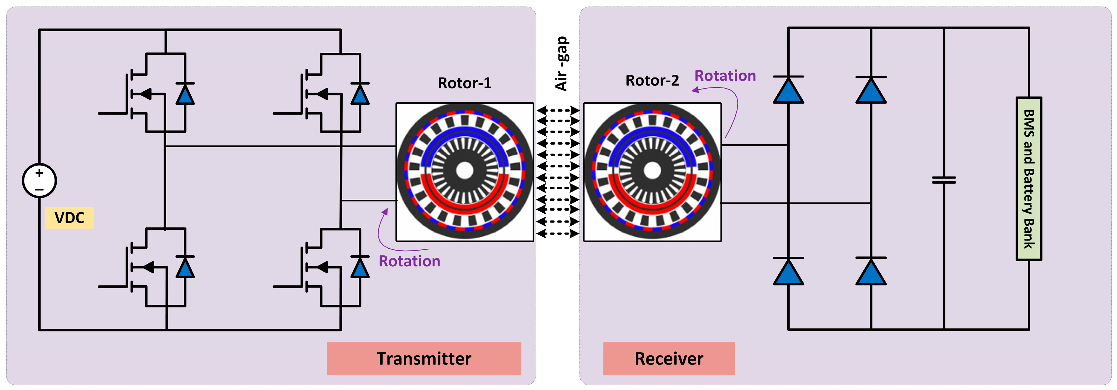
Magnetic Gear Wireless Chargers
4.3. Control of Chargers
4.3.1. Control of Conductive Chargers
4.3.2. Control of Wireless Chargers
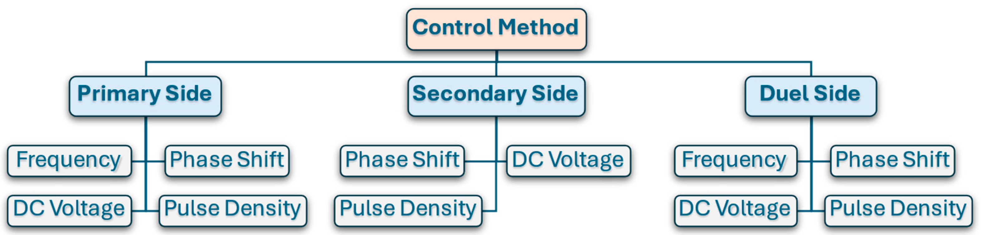
Primary Side Control
Secondary Side Control
Dual Side Control
5. Electric Motors
5.1. Induction Motor (IM)
5.2. Permanent Magnet Synchronous Motor (PMSM)
5.3. Synchronous Reluctance Motor (SynRM) and Switched Reluctance Motor (SRM)
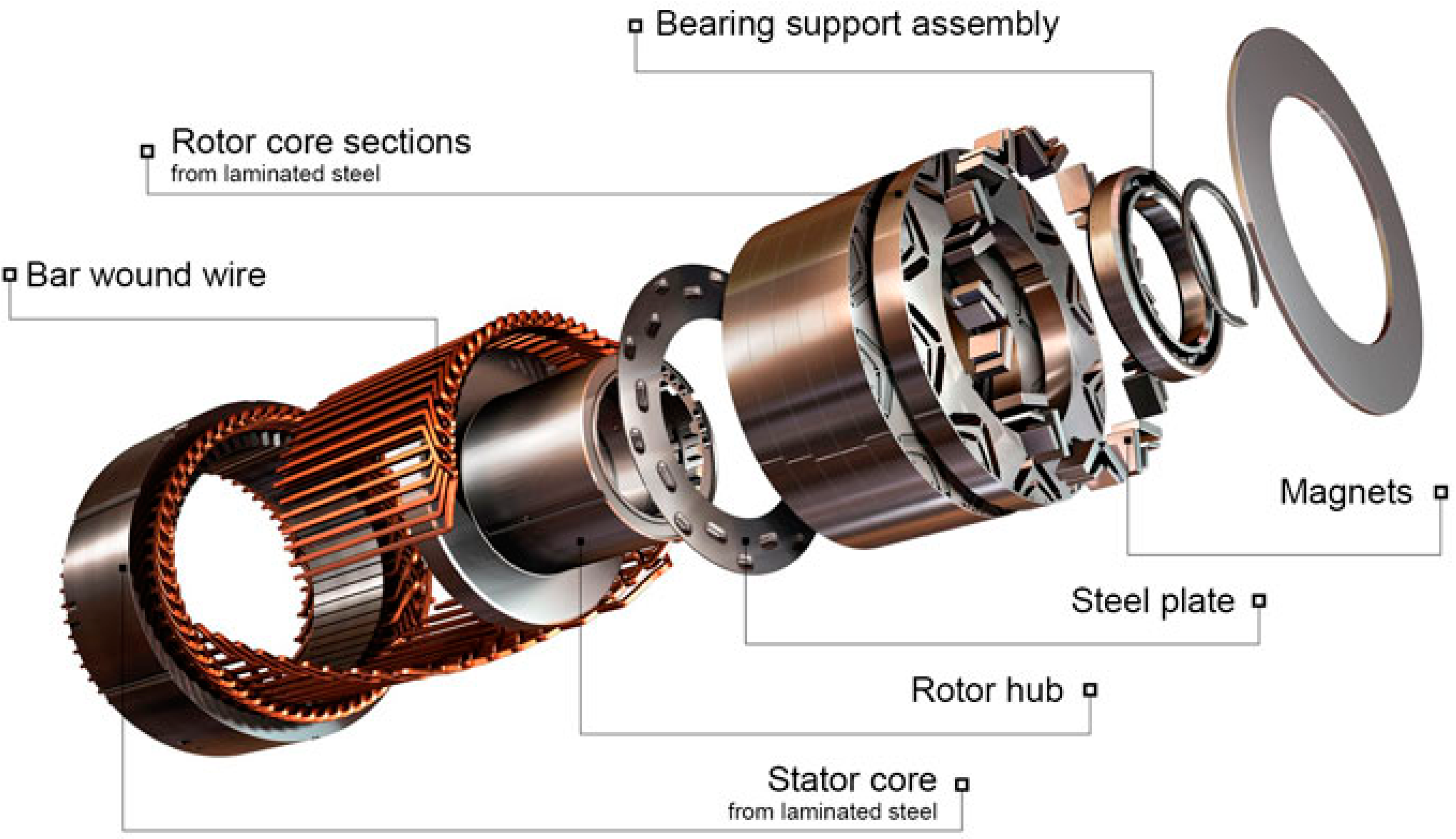
5.4. Axial Flux Motors
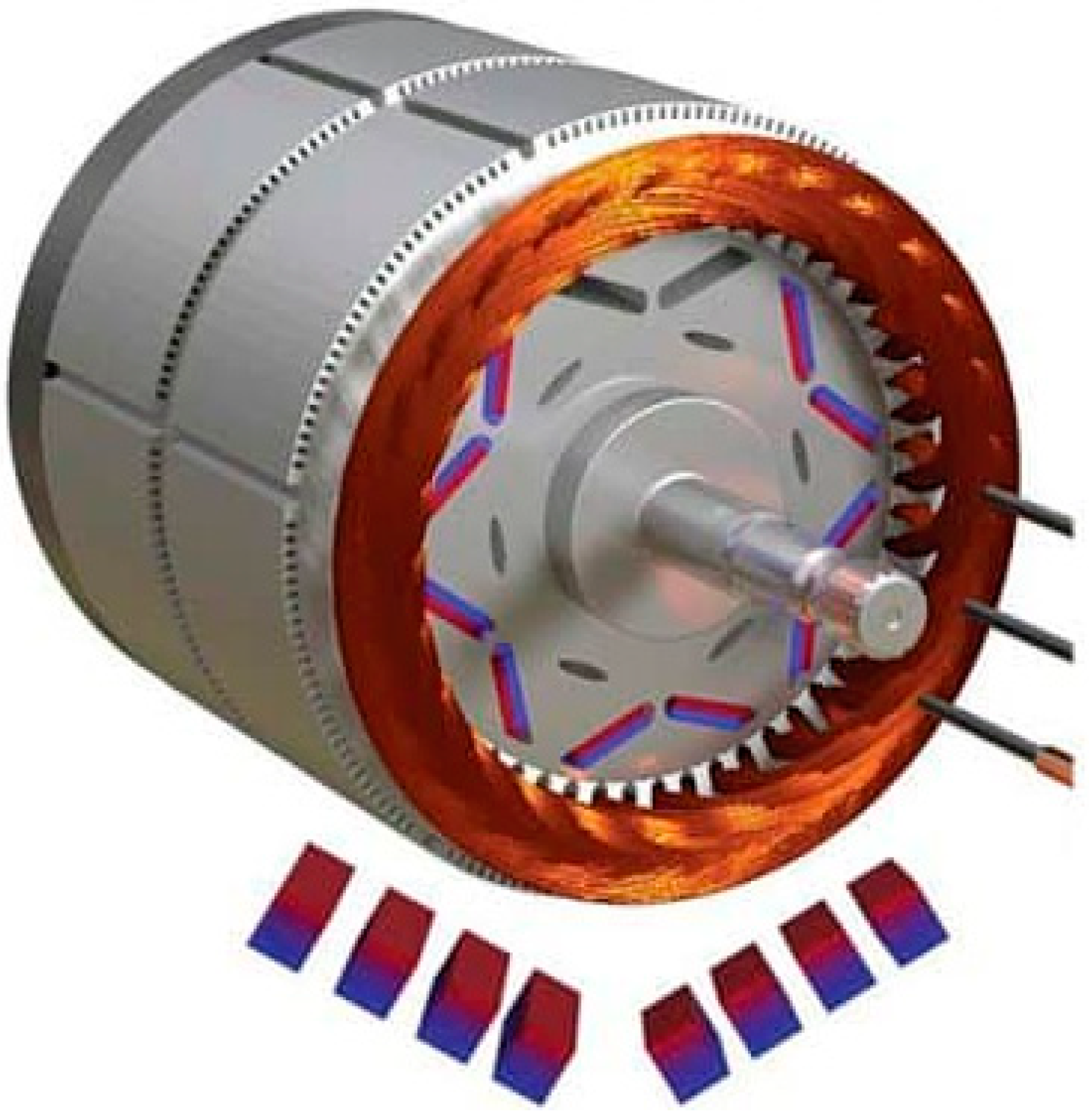
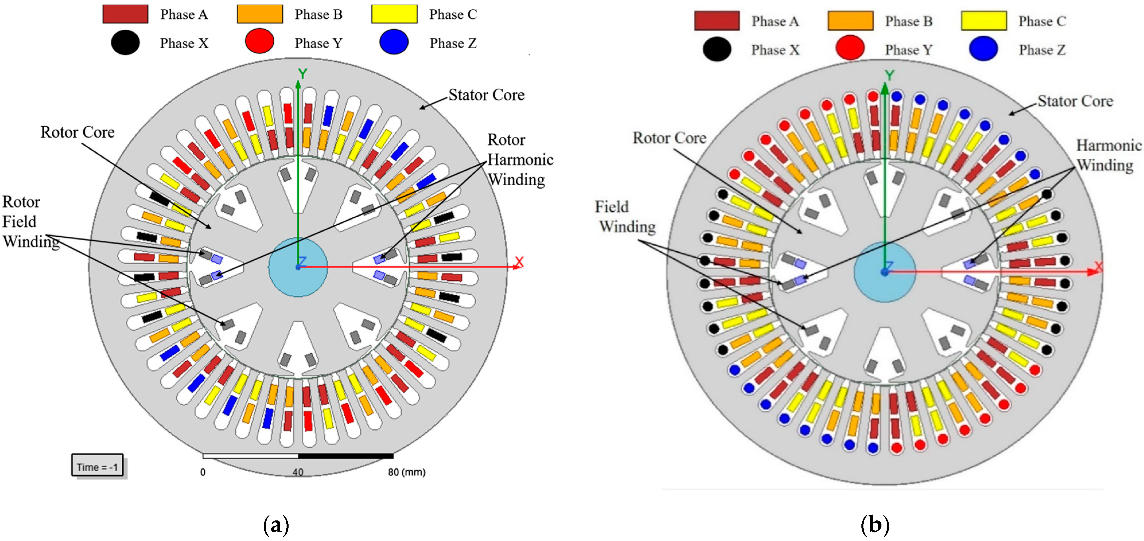
5.5. Sub-Harmonic Synchronous Machine (SHSM)
5.6. Requirements of Motor Performance for Electric Vehicles
6. Standards and Regulations
7. Conclusions
Author Contributions
Funding
Data Availability Statement
Conflicts of Interest
References
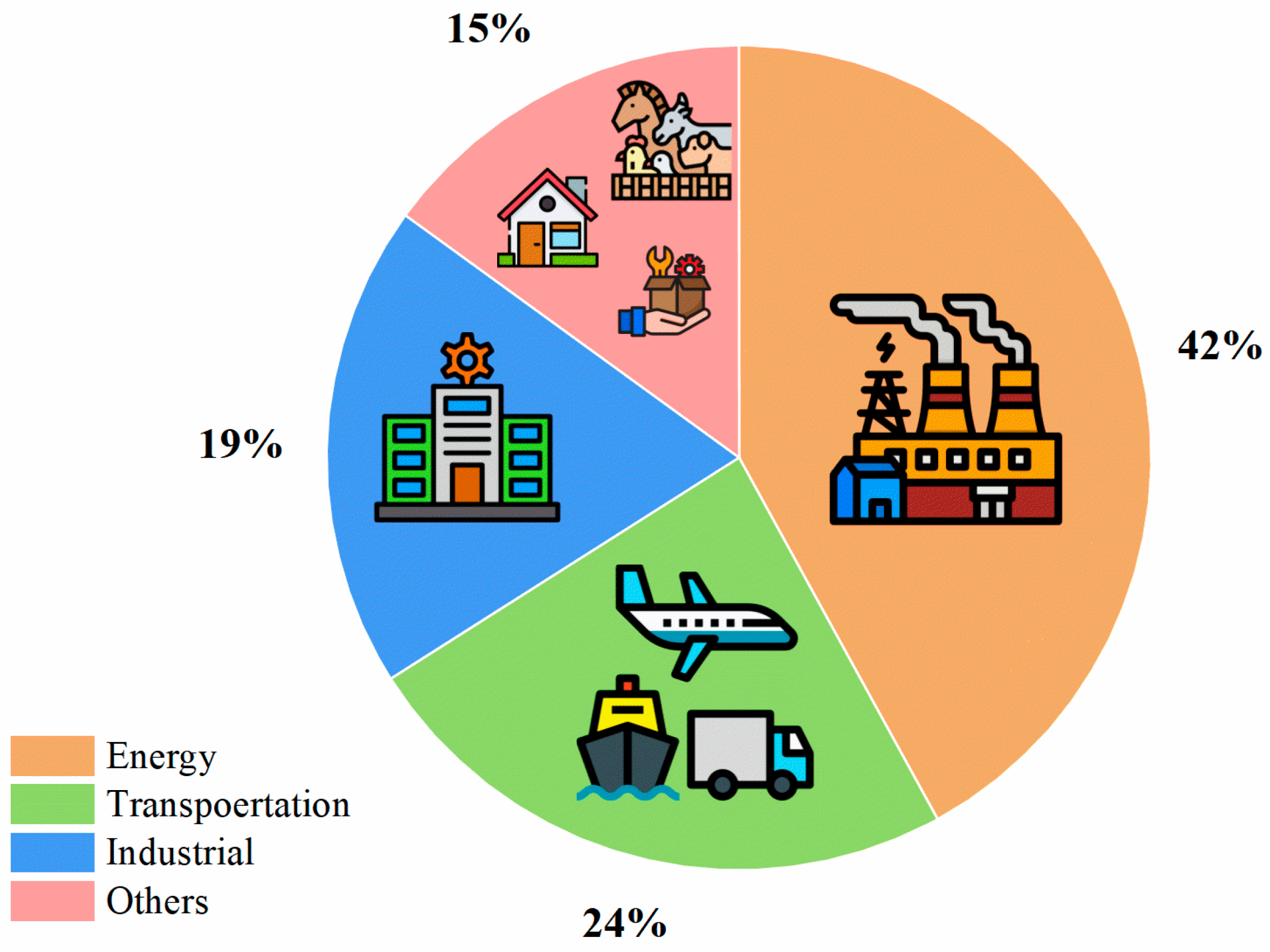
- Oladunni, O.J.; Mpofu, K.; Olanrewaju, O.A. Greenhouse gas emissions and its driving forces in the transport sector of South Africa. Energy Rep. 2022, 8, 2052–2061. [Google Scholar] [CrossRef]
- Bleviss, D.L. Transportation is critical to reducing greenhouse gas emissions in the United States. WIREs Energy Environ. 2021, 10, e390. [Google Scholar] [CrossRef]
- Feng, T.-T.; Yang, Y.-S.; Xie, S.-Y.; Dong, J.; Ding, L. Economic drivers of greenhouse gas emissions in China. Renew. Sustain. Energy Rev. 2017, 78, 996–1006. [Google Scholar] [CrossRef]
- Alcántara, V.; Padilla, E. Key sectors in greenhouse gas emissions in Spain: An alternative input–output analysis. J. Ind. Ecol. 2020, 24, 577–588. [Google Scholar] [CrossRef]
- Inventory of, U.S. Greenhouse Gas Emissions and Sinks: 1990–2022|US EPA. Available online: https://www.epa.gov/ghgemissions/inventory-us-greenhouse-gas-emissions-and-sinks-1990-2022 (accessed on 29 July 2024).
- Rajper, S.Z.; Albrecht, J. Prospects of Electric Vehicles in the Developing Countries: A Literature Review. Sustainability 2020, 12, 1906. [Google Scholar] [CrossRef]
- Langbroek, J.H.M.; Franklin, J.P.; Susilo, Y.O. The Effect of Policy Incentives on Electric Vehicle Adoption. Energy Policy 2016, 94, 94–103. [Google Scholar] [CrossRef]
- Agrawal, M.; Rajapatel, M.S. Global perspective on electric vehicle 2020. Int. J. Eng. Res. Technol. 2020, 9, 8–11. [Google Scholar] [CrossRef]
- Albatayneh, A.; Assaf, M.N.; Alterman, D.; Jaradat, M. Comparison of the Overall Energy Efficiency for Internal Combustion Engine Vehicles and Electric Vehicles. Sci. J. Riga Tech. Univ. Environ. Clim. Technol. 2020, 24, 669–680. [Google Scholar] [CrossRef]
- Muratori, M.; Alexander, M.; Arent, D.; Bazilian, M.; Cazzola, P.; Dede, E.M.; Farrell, J.; Gearhart, C.; Greene, D.; Jenn, A.; et al. The rise of electric vehicles—2020 status and future expectations. Prog. Energy 2021, 3, 022002. [Google Scholar] [CrossRef]
- Global EV Outlook 2019—Analysis—IEA. Available online: https://www.iea.org/reports/global-ev-outlook-2019 (accessed on 29 July 2024).
- Global EV Outlook 2017—Analysis—IEA. Available online: https://www.iea.org/reports/global-ev-outlook-2017 (accessed on 29 July 2024).
- Quarterly Electric Car Sales by Region, 2021–2024—Charts—Data & Statistics—IEA. Available online: https://www.iea.org/data-and-statistics/charts/quarterly-electric-car-sales-by-region-2021-2024 (accessed on 29 July 2024).
- Hasan, M.K.; Mahmud; Habib, A.A.; Motakabber, S.; Islam, S. Review of electric vehicle energy storage and management system: Standards, issues, and challenges. J. Energy Storage 2021, 41, 102940. [Google Scholar] [CrossRef]
- Ntombela, M.; Musasa, K.; Moloi, K. A Comprehensive Review for Battery Electric Vehicles (BEV) Drive Circuits Technology, Operations, and Challenges. World Electr. Veh. J. 2023, 14, 195. [Google Scholar] [CrossRef]
- Ehsani, M.; Singh, K.V.; Bansal, H.O.; Mehrjardi, R.T. State of the Art and Trends in Electric and Hybrid Electric Vehicles. Proc. IEEE 2021, 109, 967–984. [Google Scholar] [CrossRef]
- Sanguesa, J.A.; Torres-Sanz, V.; Garrido, P.; Martinez, F.J.; Marquez-Barja, J.M. A Review on Electric Vehicles: Technologies and Challenges. Smart Cities 2021, 4, 372–404. [Google Scholar] [CrossRef]
- Singh, K.V.; Bansal, H.O.; Singh, D. A comprehensive review on hybrid electric vehicles: Architectures and components. J. Mod. Transp. 2019, 27, 77–107. [Google Scholar] [CrossRef]
- Acharige, S.S.G.; Haque, E.; Arif, M.T.; Hosseinzadeh, N.; Hasan, K.N.; Oo, A.M.T. Review of Electric Vehicle Charging Technologies, Standards, Architectures, and Converter Configurations. IEEE Access 2023, 11, 41218–41255. [Google Scholar] [CrossRef]
- Ghosh, A. Possibilities and Challenges for the Inclusion of the Electric Vehicle (EV) to Reduce the Carbon Footprint in the Transport Sector: A Review. Energies 2020, 13, 2602. [Google Scholar] [CrossRef]
- Thangavel, S.; Mohanraj, D.; Girijaprasanna, T.; Raju, S.; Dhanamjayulu, C.; Muyeen, S.M. A Comprehensive Review on Electric Vehicle: Battery Management System, Charging Station, Traction Motors. IEEE Access 2023, 11, 20994–21019. [Google Scholar] [CrossRef]
- Sathiyan, S.P.; Pratap, C.B.; Stonier, A.A.; Peter, G.; Sherine, A.; Praghash, K.; Ganji, V. Comprehensive Assessment of Electric Vehicle Development, Deployment, and Policy Initiatives to Reduce GHG Emissions: Opportunities and Challenges. IEEE Access 2022, 10, 53614–53639. [Google Scholar] [CrossRef]
- Stajić, D.; Pfeifer, A.; Herc, L.; Logonder, M. Early Adoption of Battery Electric Vehicles and Owners’ Motivation. Clean. Eng. Technol. 2023, 15, 100658. [Google Scholar] [CrossRef]
- Koroma, M.S.; Costa, D.; Philippot, M.; Cardellini, G.; Hosen, M.S.; Coosemans, T.; Messagie, M. Life Cycle Assessment of Battery Electric Vehicles: Implications of Future Electricity Mix and Different Battery End-of-Life Management. Sci. Total Environ. 2022, 831, 154859. [Google Scholar] [CrossRef]
- Liu, X.; Zhao, F.; Geng, J.; Hao, H.; Liu, Z. Comprehensive Assessment for Different Ranges of Battery Electric Vehicles: Is It Necessary to Develop an Ultra-Long Range Battery Electric Vehicle? iScience 2023, 26, 106654. [Google Scholar] [CrossRef] [PubMed]
- Björnsson, L.H.; Karlsson, S. Electrification of the Two-Car Household: PHEV or BEV? Transp. Res. Part C Emerg. Technol. 2017, 85, 363–376. [Google Scholar] [CrossRef]
- Wang, Y.; Biswas, A.; Rodriguez, R.; Keshavarz-Motamed, Z.; Emadi, A. Hybrid Electric Vehicle Specific Engines: State-of-the-Art Review. Energy Rep. 2022, 8, 832–851. [Google Scholar] [CrossRef]
- Tran, D.D.; Vafaeipour, M.; El Baghdadi, M.; Barrero, R.; Van Mierlo, J.; Hegazy, O. Thorough State-of-the-Art Analysis of Electric and Hybrid Vehicle Powertrains: Topologies and Integrated Energy Management Strategies. Renew. Sustain. Energy Rev. 2020, 119, 109596. [Google Scholar] [CrossRef]
- Yong, J.Y.; Ramachandaramurthy, V.K.; Tan, K.M.; Mithulananthan, N. A Review on the State-of-the-Art Technologies of Electric Vehicle, Its Impacts and Prospects. Renew. Sustain. Energy Rev. 2015, 49, 365–385. [Google Scholar] [CrossRef]
- Fantin Irudaya Raj, E.; Appadurai, M. The Hybrid Electric Vehicle (HEV)—An Overview. In Emerging Solutions for e-Mobility and Smart Grids; Springer: Singapore, 2021; pp. 25–36. [Google Scholar] [CrossRef]
- Shen, C.; Shan, P.; Gao, T. A Comprehensive Overview of Hybrid Electric Vehicles. Int. J. Veh. Technol. 2011, 2011, 571683. [Google Scholar] [CrossRef]
- Yang, C.; Zha, M.; Wang, W.; Liu, K.; Xiang, C. Efficient Energy Management Strategy for Hybrid Electric Vehicles/Plug-in Hybrid Electric Vehicles: Review and Recent Advances under Intelligent Transportation System. IET Intell. Transp. Syst. 2020, 14, 702–711. [Google Scholar] [CrossRef]
- Sabri, M.; Danapalasingam, K.A.; Rahmat, M.F. A review on hybrid electric vehicles architecture and energy management strategies. Renew. Sustain. Energy Rev. 2016, 53, 1433–1442. [Google Scholar] [CrossRef]
- León, R.; Montaleza, C.; Maldonado, J.L.; Tostado-Véliz, M.; Jurado, F. Hybrid Electric Vehicles: A Review of Existing Configurations and Thermodynamic Cycles. Thermo 2021, 1, 134–150. [Google Scholar] [CrossRef]
- Selmi, T.; Khadhraoui, A.; Cherif, A. Fuel Cell–Based Electric Vehicles Technologies and Challenges. Environ. Sci. Pollut. Res. 2022, 29, 78121–78131. [Google Scholar] [CrossRef]
- Muthukumar, M.; Rengarajan, N.; Velliyangiri, B.; Omprakas, M.A.; Rohit, C.B.; Raja, U.K. The Development of Fuel Cell Electric Vehicles—A Review. Mater Today Proc. 2021, 45, 1181–1187. [Google Scholar] [CrossRef]
- Waseem, M.; Amir, M.; Lakshmi, G.S.; Harivardhagini, S.; Ahmad, M. Fuel Cell-Based Hybrid Electric Vehicles: An Integrated Review of Current Status, Key Challenges, Recommended Policies, and Future Prospects. Green Energy Intell. Transp. 2023, 2, 100121. [Google Scholar] [CrossRef]
- Oldenbroek, V.; Wijtzes, S.; Blok, K.; van Wijk, A.J.M. Fuel Cell Electric Vehicles and Hydrogen Balancing 100 Percent Renewable and Integrated National Transportation and Energy Systems. Energy Convers. Manag. X 2021, 9, 100077. [Google Scholar] [CrossRef]
- Wu, D.; Ren, J.; Davies, H.; Shang, J.; Haas, O. Intelligent Hydrogen Fuel Cell Range Extender for Battery Electric Vehicles. World Electr. Veh. J. 2019, 10, 29. [Google Scholar] [CrossRef]
- Tsang, F.; Potoglou, D.; Wooding, S.; Pedersen, J.S. Bringing the Electric Vehicle to the Mass Market: A Review of Barriers, Facilitators and Policy Interventions; RAND Corporation: Santa Monica, CA, USA, 2012. [Google Scholar]
- Sufyan Arshad Ayesha Ashraf, M. Hybrid Electric Vehicles: A General Overview. Int. J. Eng. Appl. Sci. Technol. 2020, 5, 21–26. [Google Scholar]
- Veza, I.; Asy’ari, M.Z.; Idris, M.; Epin, V.; Rizwanul Fattah, I.M.; Spraggon, M. Electric Vehicle (EV) and Driving towards Sustainability: Comparison between EV, HEV, PHEV, and ICE Vehicles to Achieve Net Zero Emissions by 2050 from EV. Alex. Eng. J. 2023, 82, 459–467. [Google Scholar] [CrossRef]
- Çaǧatay Bayindir, K.; Gözüküçük, M.A.; Teke, A. A Comprehensive Overview of Hybrid Electric Vehicle: Powertrain Configurations, Powertrain Control Techniques and Electronic Control Units. Energy Convers. Manag. 2011, 52, 1305–1313. [Google Scholar] [CrossRef]
- Ma, Z.; Luan, Y.; Zhang, F.; Xie, S.; Coskun, S. A Data-Driven Energy Management Strategy for Plug-in Hybrid Electric Buses Considering Vehicle Mass Uncertainty. J. Energy Storage 2024, 77, 109963. [Google Scholar] [CrossRef]
- Gong, W.; Liu, C.; Zhao, X.; Xu, S. A Model Review for Controller-Hardware-in-the- Loop Simulation in EV Powertrain Application. IEEE Trans. Transp. Electrif. 2024, 10, 925–937. [Google Scholar] [CrossRef]
- Xu, C.; Behrens, P.; Gasper, P.; Smith, K.; Hu, M.; Tukker, A.; Steubing, B. Electric vehicle batteries alone could satisfy short-term grid storage demand by as early as 2030. Nat. Commun. 2023, 14, 119. [Google Scholar] [CrossRef]
- Koohi-Fayegh, S.; Rosen, M.A. A Review of Energy Storage Types, Applications and Recent Developments. J. Energy Storage 2020, 27, 101047. [Google Scholar] [CrossRef]
- Hussein, H.M.; Abdelrahman, M.S.; Rafin, S.M.S.H.; Kharchouf, I.; Mohammed, O. Enhancing Stability of Hybrid AC/DC Microgrid-Based Battery/Ultracapacitor Energy Storage System. In Proceedings of the 2024 IEEE International Conference on Environment and Electrical Engineering and 2024 IEEE Industrial and Commercial Power Systems Europe (EEEIC/I&CPS Europe), Rome, Italy, 17–20 June 2024. [Google Scholar]
- Kumar, D.; Nema, R.K.; Gupta, S. A Comparative Review on Power Conversion Topologies and Energy Storage System for Electric Vehicles. Int. J. Energy Res. 2020, 44, 7863–7885. [Google Scholar] [CrossRef]
- Gao, Z.; Xie, H.; Yang, X.; Niu, W.; Li, S.; Chen, S. The Dilemma of C-Rate and Cycle Life for Lithium-Ion Batteries under Low Temperature Fast Charging. Batteries 2022, 8, 234. [Google Scholar] [CrossRef]
- Ralls, A.M.; Leong, K.; Clayton, J.; Fuelling, P.; Mercer, C.; Navarro, V.; Menezes, P.L. The Role of Lithium-Ion Batteries in the Growing Trend of Electric Vehicles. Materials 2023, 16, 6063. [Google Scholar] [CrossRef]
- Chen, W.; Liang, J.; Yang, Z.; Li, G. A Review of Lithium-Ion Battery for Electric Vehicle Applications and Beyond. Energy Procedia 2019, 158, 4363–4368. [Google Scholar] [CrossRef]
- Notter, D.A.; Gauch, M.; Widmer, R.; Wäger, P.; Stamp, A.; Zah, R.; Althaus, H.J. Contribution of Li-Ion Batteries to the Environmental Impact of Electric Vehicles. Environ. Sci. Technol. 2010, 44, 6550–6556. [Google Scholar] [CrossRef]
- Bisschop, R.; Willstrand, O.; Amon, F.; Rosenggren, M. Fire Safety of Lithium-Ion Batteries in Road Vehicles; RISE Report 2019; 2019; Volume 50, p. 105. Available online: https://urn.kb.se/resolve?urn=urn:nbn:se:ri:diva-38873 (accessed on 30 July 2024).
- Chen, Y.; Kang, Y.; Zhao, Y.; Wang, L.; Liu, J.; Li, Y.; Liang, Z.; He, X.; Li, X.; Tavajohi, N.; et al. A Review of Lithium-Ion Battery Safety Concerns: The Issues, Strategies, and Testing Standards. J. Energy Chem. 2021, 59, 83–99. [Google Scholar] [CrossRef]
- Diaz, L.B.; He, X.; Hu, Z.; Restuccia, F.; Marinescu, M.; Barreras, J.V.; Patel, Y.; Offer, G.J.; Rein, G. Review—Meta-Review of Fire Safety of Lithium-Ion Batteries: Industry Challenges and Research Contributions. J. Electrochem. Soc. 2020, 167, 090559. [Google Scholar] [CrossRef]
- Chen, Y.; Wang, T.; Tian, H.; Su, D.; Zhang, Q.; Wang, G.; Chen, Y.; Wang, T.; Tian, H.; Su, D.; et al. Advances in Lithium–Sulfur Batteries: From Academic Research to Commercial Viability. Adv. Mater. 2021, 33, 2003666. [Google Scholar] [CrossRef]
- Manthiram, A. An Outlook on Lithium Ion Battery Technology. ACS Cent Sci. 2017, 3, 1063–1069. [Google Scholar] [CrossRef]
- Ding, Y.; Cano, Z.P.; Yu, A.; Lu, J.; Chen, Z. Automotive Li-Ion Batteries: Current Status and Future Perspectives. Electrochem. Energy Rev. 2019, 2, 1–28. [Google Scholar] [CrossRef]
- Hochschulschriften/Increasing Electric Vehicle Range with a Recommendation App Providing ContextSpecific Trip Rankings. Available online: https://epub.jku.at/urn:nbn:at:at-ubl:1-12684 (accessed on 30 July 2024).
- Leone, C.; Sturaro, L.; Geroli, G.; Longo, M.; Yaici, W. Design and Implementation of an Electric Skibus Line in North Italy. Energies 2021, 14, 7925. [Google Scholar] [CrossRef]
- Sutopo, W.; Maryanie, D.I.; Purwanto, A.; Nizam, M. A Comparative Value Chains Analysis of Battery Technologies for Electric Vehicles. In Proceedings of the 2013 Joint International Conference on Rural Information and Communication Technology and Electric-Vehicle Technology, rICT and ICEV-T 2013, Bandung, Indonesia, 26–28 November 2013. [Google Scholar] [CrossRef]
- Windisch-Kern, S.; Gerold, E.; Nigl, T.; Jandric, A.; Altendorfer, M.; Rutrecht, B.; Scherhaufer, S.; Raupenstrauch, H.; Pomberger, R.; Antrekowitsch, H.; et al. Recycling Chains for Lithium-Ion Batteries: A Critical Examination of Current Challenges, Opportunities and Process Dependencies. Waste Manag. 2022, 138, 125–139. [Google Scholar] [CrossRef]
- Wu, J.; Dathar, G.K.P.; Sun, C.; Theivanayagam, M.G.; Applestone, D.; Dylla, A.G.; Manthiram, A.; Henkelman, G.; Goodenough, J.B.; Stevenson, K.J. In Situ Raman Spectroscopy of LiFePO4: Size and Morphology Dependence during Charge and Self-Discharge. Nanotechnology 2013, 24, 424009. [Google Scholar] [CrossRef] [PubMed]
- Andre, D.; Kim, S.J.; Lamp, P.; Lux, S.F.; Maglia, F.; Paschos, O.; Stiaszny, B. Future Generations of Cathode Materials: An Automotive Industry Perspective. J. Mater. Chem. A Mater. 2015, 3, 6709–6732. [Google Scholar] [CrossRef]
- Baczyńska, A.; Niewiadomski, W.; Gonçalves, A.; Almeida, P.; Luís, R. Li-NMC Batteries Model Evaluation with Experimental Data for Electric Vehicle Application. Batteries 2018, 4, 11. [Google Scholar] [CrossRef]
- Hammou, A.; Petrone, R.; Diallo, D.; Gualous, H. Estimating the Health Status of Li-Ion NMC Batteries from Energy Characteristics for EV Applications. IEEE Trans. Energy Convers. 2023, 38, 2160–2168. [Google Scholar] [CrossRef]
- Liu, X.; Li, K.; Li, X. The Electrochemical Performance and Applications of Several Popular Lithium-Ion Batteries for Electric Vehicles—A Review. Commun. Comput. Inf. Sci. 2018, 925, 201–213. [Google Scholar]
- de Castro, R.H.; Romano Espinosa, D.C.; Gobo, L.A.; Kumoto, E.A.; Botelho Junior, A.B.; Tenorio, J.A.S. Design of Recycling Processes for NCA-Type Li-Ion Batteries from Electric Vehicles toward the Circular Economy. Energy Fuels 2024, 38, 5545–5557. [Google Scholar] [CrossRef]
- Tran, M.K.; Dacosta, A.; Mevawalla, A.; Panchal, S.; Fowler, M. Comparative Study of Equivalent Circuit Models Performance in Four Common Lithium-Ion Batteries: LFP, NMC, LMO, NCA. Batteries 2021, 7, 51. [Google Scholar] [CrossRef]
- Han, X.; Ouyang, M.; Lu, L.; Li, J. Cycle Life of Commercial Lithium-Ion Batteries with Lithium Titanium Oxide Anodes in Electric Vehicles. Energies 2014, 7, 4895–4909. [Google Scholar] [CrossRef]
- Al-saadi, M.; Olmos, J.; Saez-de-ibarra, A.; Van Mierlo, J.; Berecibar, M. Fast Charging Impact on the Lithium-Ion Batteries’ Lifetime and Cost-Effective Battery Sizing in Heavy-Duty Electric Vehicles Applications. Energies 2022, 15, 1278. [Google Scholar] [CrossRef]
- Guittet, D.; Gasper, P.; Shirk, M.; Mitchell, M.; Gilleran, M.; Bonnema, E.; Smith, K.; Mishra, P.; Mann, M. Levelized Cost of Charging of Extreme Fast Charging with Stationary LMO/LTO Batteries. J. Energy Storage 2024, 82, 110568. [Google Scholar] [CrossRef]
- Arya, S.; Verma, S. Nickel-Metal Hydride (Ni-MH) Batteries. Recharg. Batter. 2020, 131–175. [Google Scholar] [CrossRef]
- Naim, A.; Vashist, D. Technological Advancements for Reduced Charging Time of Electric Vehicle Batteries: A Review. Smart Struct. Energy Infrastruct. Proc. ICRTE 2022, 2, 99–112. [Google Scholar] [CrossRef]
- Arun, V.; Kannan, R.; Ramesh, S.; Vijayakumar, M.; Raghavendran, P.S.; Siva Ramkumar, M.; Anbarasu, P.; Sundramurthy, V.P. Review on Li-Ion Battery vs Nickel Metal Hydride Battery in EV. Adv. Mater. Sci. Eng. 2022, 2022, 7910072. [Google Scholar] [CrossRef]
- Fetcenko, M.A.; Ovshinsky, S.R.; Reichman, B.; Young, K.; Fierro, C.; Koch, J.; Zallen, A.; Mays, W.; Ouchi, T. Recent Advances in NiMH Battery Technology. J. Power Sources 2007, 165, 544–551. [Google Scholar] [CrossRef]
- Kang, J.; Yan, F.; Zhang, P.; Du, C. Comparison of Comprehensive Properties of Ni-MH (Nickel-Metal Hydride) and Li-Ion (Lithium-Ion) Batteries in Terms of Energy Efficiency. Energy 2014, 70, 618–625. [Google Scholar] [CrossRef]
- Aditya, J.P.; Ferdowsi, M. Comparison of NiMH and Li-Ion Batteries in Automotive Applications. In Proceedings of the 2008 IEEE Vehicle Power and Propulsion Conference, VPPC 2008, Harbin, China, 3–5 September 2008. [Google Scholar] [CrossRef]
- Chang, S.; Young, K.H.; Lien, Y.L. Reviews of European Patents on Nickel/Metal Hydride Batteries. Batteries 2017, 3, 25. [Google Scholar] [CrossRef]
- Zhu, W.H.; Zhu, Y.; Tatarchuk, B.J. Self-Discharge Characteristics and Performance Degradation of Ni-MH Batteries for Storage Applications. Int. J. Hydrogen Energy 2014, 39, 19789–19798. [Google Scholar] [CrossRef]
- Young, K.H.; Yasuoka, S. Capacity Degradation Mechanisms in Nickel/Metal Hydride Batteries. Batteries 2016, 2, 3. [Google Scholar] [CrossRef]
- Ouyang, L.; Huang, J.; Wang, H.; Liu, J.; Zhu, M. Progress of Hydrogen Storage Alloys for Ni-MH Rechargeable Power Batteries in Electric Vehicles: A Review. Mater. Chem. Phys. 2017, 200, 164–178. [Google Scholar] [CrossRef]
- Mohammadi, F.; Saif, M. A Comprehensive Overview of Electric Vehicle Batteries Market. e-Prime Adv. Electr. Eng. Electron. Energy 2023, 3, 100127. [Google Scholar] [CrossRef]
- Li, G.; Lu, X.; Kim, J.Y.; Viswanathan, V.V.; Meinhardt, K.D.; Engelhard, M.H.; Sprenkle, V.L. An Advanced Na–FeCl2 ZEBRA Battery for Stationary Energy Storage Application. Adv. Energy Mater. 2015, 5, 1500357. [Google Scholar] [CrossRef]
- Sudworth, J.L. Zebra Batteries. J. Power Sources 1994, 51, 105–114. [Google Scholar] [CrossRef]
- Dustmann, C.H. Advances in ZEBRA Batteries. J. Power Sources 2004, 127, 85–92. [Google Scholar] [CrossRef]
- Sudworth, J.L. The Sodium/Nickel Chloride (ZEBRA) Battery. J. Power Sources 2001, 100, 149–163. [Google Scholar] [CrossRef]
- Shamim, N.; Thomsen, E.C.; Viswanathan, V.V.; Reed, D.M.; Sprenkle, V.L.; Li, G. Evaluating ZEBRA Battery Module under the Peak-Shaving Duty Cycles. Materials 2021, 14, 2280. [Google Scholar] [CrossRef]
- Leonardi, S.G.; Samperi, M.; Frusteri, L.; Antonucci, V.; D’Urso, C. A Review of Sodium-Metal Chloride Batteries: Materials and Cell Design. Batteries 2023, 9, 524. [Google Scholar] [CrossRef]
- Hu, Y.; Wu, X.; Wen, Z.; Hou, M.; Yi, B. Challenges and Thoughts on the Development of Sodium Battery Technology for Energy Storage. Strateg. Study Chin. Acad. Eng. 2021, 23, 94–102. [Google Scholar] [CrossRef]
- Nikolic, M.; Schelte, N.; Velenderic, M.; Adjei, F.; Severengiz, S. Life Cycle Assessment of Sodium-Nickel-Chloride Batteries. In Proceedings of the International Renewable Energy Storage Conference (IRES 2022), Düsseldorf, Germany, 20–22 September 2023; pp. 336–362. [Google Scholar]
- Dixon, J.; Nakashima, I.; Arcos, E.F.; Ortúzar, M. Electric Vehicle Using a Combination of Ultracapacitors and ZEBRA Battery. IEEE Trans. Ind. Electron. 2010, 57, 943–949. [Google Scholar] [CrossRef]
- Capasso, C.; Veneri, O. Integration between Super-Capacitors and ZEBRA Batteries as High Performance Hybrid Storage System for Electric Vehicles. Energy Procedia 2017, 105, 2539–2544. [Google Scholar] [CrossRef]
- Moradi, Z.; Lanjan, A.; Tyagi, R.; Srinivasan, S. Review on Current State, Challenges, and Potential Solutions in Solid-State Batteries Research. J. Energy Storage 2023, 73, 109048. [Google Scholar] [CrossRef]
- Chen, M.; Winiarz, P.; Luo, J.; Qi, K.; Thomas, F.; Mahdi, L.; Lemaire, J.; Santos, D.M.F. Technological Advances and Market Developments of Solid-State Batteries: A Review. Materials 2024, 17, 239. [Google Scholar] [CrossRef] [PubMed]
- Li, S.; Jiang, M.; Xie, Y.; Xu, H.; Jia, J.; Li, J.; Li, S.; Jiang, M.; Xie, Y.; Xu, H.; et al. Developing High-Performance Lithium Metal Anode in Liquid Electrolytes: Challenges and Progress. Adv. Mater. 2018, 30, 1706375. [Google Scholar] [CrossRef]
- Machín, A.; Morant, C.; Márquez, F. Advancements and Challenges in Solid-State Battery Technology: An In-Depth Review of Solid Electrolytes and Anode Innovations. Batteries 2024, 10, 29. [Google Scholar] [CrossRef]
- Zheng, Y.; Yao, Y.; Ou, J.; Li, M.; Luo, D.; Dou, H.; Li, Z.; Amine, K.; Yu, A.; Chen, Z. A Review of Composite Solid-State Electrolytes for Lithium Batteries: Fundamentals, Key Materials and Advanced Structures. Chem. Soc. Rev. 2020, 49, 8790–8839. [Google Scholar] [CrossRef]
- Yang, T.; Wang, C.; Zhang, W.; Xia, Y.; Huang, H.; Gan, Y.; He, X.; Xia, X.; Tao, X.; Zhang, J. A Critical Review on Composite Solid Electrolytes for Lithium Batteries: Design Strategies and Interface Engineering. J. Energy Chem. 2023, 84, 189–209. [Google Scholar] [CrossRef]
- Pavlov, D. Lead-Acid Batteries: Science and Technology; Elsevier: Amsterdam, The Netherlands, 2011; pp. 1–643. [Google Scholar] [CrossRef]
- Garche, J.; Moseley, P.T.; Karden, E. Lead–acid batteries for hybrid electric vehicles and battery electric vehicles. In Advances in Battery Technologies for Electric Vehicles; Woodhead Publishing: Sawston, UK, 2015; pp. 75–101. [Google Scholar] [CrossRef]
- May, G.; Davidson, A.; Monahov, B. Lead batteries for utility energy storage: A review. J. Energy Storage 2018, 15, 145–157. Available online: https://www.sciencedirect.com/science/article/pii/S2352152X17304437 (accessed on 30 July 2024). [CrossRef]
- Lopes, P.P.; Stamenkovic, V.R. Past, Present, and Future of Lead–Acid Batteries. Science 2020, 369, 923–924. [Google Scholar] [CrossRef]
- Chen, H. Electrolytes of lead-acid batteries. In Lead-Acid Battery Technologies: Fundamentals, Materials, and Applications; CRC Press: Boca Raton, FL, USA, 2015; pp. 137–162. [Google Scholar] [CrossRef]
- Gelbke, M.; Mondoloni, C. Flooded starting-lighting-ignition (SLI) and enhanced flooded batteries (EFBs): State-of-the-art’. In Lead-Acid Batteries for Future Automobiles; Elsevier: Amsterdam, The Netherlands, 2017; pp. 149–184. [Google Scholar] [CrossRef]
- McKeon, B.B.; Furukawa, J.; Fenstermacher, S. Advanced Lead-Acid Batteries and the Development of Grid-Scale Energy Storage Systems. Proc. IEEE 2014, 102, 951–963. [Google Scholar] [CrossRef]
- Vangapally, N.; Penki, T.R.; Elias, Y.; Muduli, S.; Maddukuri, S.; Luski, S.; Aurbach, D.; Martha, S.K. Lead-Acid Batteries and Lead–Carbon Hybrid Systems: A Review. J. Power Sources 2023, 579, 233312. [Google Scholar] [CrossRef]
- Noga, M.; Juda, Z. The Application of Nimh Batteries in a Light-Duty Electric Vehicle. Czas. Tech. 2019, 1, 197–222. [Google Scholar] [CrossRef]
- Gerssen-Gondelach, S.J.; Faaij, A.P.C. Performance of Batteries for Electric Vehicles on Short and Longer Term. J. Power Sources 2012, 212, 111–129. [Google Scholar] [CrossRef]
- Poonam; Sharma, K.; Arora, A.; Tripathi, S.K. Review of Supercapacitors: Materials and Devices. J. Energy Storage 2019, 21, 801–825. [Google Scholar] [CrossRef]
- Guo, L.; Hu, P.; Wei, H. Development of Supercapacitor Hybrid Electric Vehicle. J. Energy Storage 2023, 65, 107269. [Google Scholar] [CrossRef]
- Gao, D.; Luo, Z.; Liu, C.; Fan, S. A Survey of Hybrid Energy Devices Based on Supercapacitors. Green Energy Environ. 2023, 8, 972–988. [Google Scholar] [CrossRef]
- Sharma, P.; Kumar, V. Current Technology of Supercapacitors: A Review. J. Electron. Mater. 2020, 49, 3520–3532. [Google Scholar] [CrossRef]
- González, A.; Goikolea, E.; Barrena, J.A.; Mysyk, R. Review on Supercapacitors: Technologies and Materials. Renew. Sustain. Energy Rev. 2016, 58, 1189–1206. [Google Scholar] [CrossRef]
- Burke, A.; Liu, Z.; Zhao, H. Present and Future Applications of Supercapacitors in Electric and Hybrid Vehicles. In Proceedings of the 2014 IEEE International Electric Vehicle Conference, IEVC 2014, Florence, Italy, 17–19 December 2014. [Google Scholar] [CrossRef]
- Horn, M.; MacLeod, J.; Liu, M.; Webb, J.; Motta, N. Supercapacitors: A New Source of Power for Electric Cars? Econ. Anal. Policy 2019, 61, 93–103. [Google Scholar] [CrossRef]
- Xu, H.; Shen, M. The Control of Lithium-Ion Batteries and Supercapacitors in Hybrid Energy Storage Systems for Electric Vehicles: A Review. Int. J. Energy Res. 2021, 45, 20524–20544. [Google Scholar] [CrossRef]
- Mounica, V.; Obulesu, Y.P. Hybrid Power Management Strategy with Fuel Cell, Battery, and Supercapacitor for Fuel Economy in Hybrid Electric Vehicle Application. Energies 2022, 15, 4185. [Google Scholar] [CrossRef]
- Battery-Supercapacitor Energy, F.; Astaneh, M.; Andric, J.; Lemian, D.; Bode, F. Battery-Supercapacitor Energy Storage Systems for Electrical Vehicles: A Review. Energies 2022, 15, 5683. [Google Scholar] [CrossRef]
- Sulaiman, N.; Hannan, M.A.; Mohamed, A.; Majlan, E.H.; Wan Daud, W.R. A Review on Energy Management System for Fuel Cell Hybrid Electric Vehicle: Issues and Challenges. Renew. Sustain. Energy Rev. 2015, 52, 802–814. [Google Scholar] [CrossRef]
- Khaligh, A.; Li, Z. Battery, Ultracapacitor, Fuel Cell, and Hybrid Energy Storage Systems for Electric, Hybrid Electric, Fuel Cell, and Plug-in Hybrid Electric Vehicles: State of the Art. IEEE Trans. Veh. Technol. 2010, 59, 2806–2814. [Google Scholar] [CrossRef]
- Cunanan, C.; Tran, M.K.; Lee, Y.; Kwok, S.; Leung, V.; Fowler, M. A Review of Heavy-Duty Vehicle Powertrain Technologies: Diesel Engine Vehicles, Battery Electric Vehicles, and Hydrogen Fuel Cell Electric Vehicles. Clean Technol. 2021, 3, 474–489. [Google Scholar] [CrossRef]
- İnci, M.; Büyük, M.; Demir, M.H.; İlbey, G. A Review and Research on Fuel Cell Electric Vehicles: Topologies, Power Electronic Converters, Energy Management Methods, Technical Challenges, Marketing and Future Aspects. Renew. Sustain. Energy Rev. 2021, 137, 110648. [Google Scholar] [CrossRef]
- Liu, W.; Placke, T.; Chau, K.T. Overview of Batteries and Battery Management for Electric Vehicles. Energy Rep. 2022, 8, 4058–4084. [Google Scholar] [CrossRef]
- Waseem, M.; Ahmad, M.; Parveen, A.; Suhaib, M. Battery Technologies and Functionality of Battery Management System for EVs: Current Status, Key Challenges, and Future Prospectives. J. Power Sources 2023, 580, 233349. [Google Scholar] [CrossRef]
- Abdelrahman, M.S.; Hussein, H.; Mohammed, O.A. Rule-Based Power and Energy Management System For Shipboard Microgrid With HESS To Mitigate Propulsion and Pulsed Load Fluctuations. In Proceedings of the 2023 IEEE Green Technologies Conference (GreenTech), Denver, CO, USA, 19–21 April 2023; pp. 224–228. [Google Scholar] [CrossRef]
- Hussein, H.M.; Aghmadi, A.; Abdelrahman, M.S.; Rafin, S.M.S.H.; Mohammed, O. A Review of Battery State of Charge Estimation and Management Systems: Models and Future Prospective. Wiley Interdiscip Rev. Energy Environ. 2024, 13, e507. [Google Scholar] [CrossRef]
- Hussein, H.; Donekal, A.; Aghmadi, A.; Rafin, S.M.S.H.; Mohammed, O.A. State of Charge Estimation Using Data-Driven Models for Inverter-Based Systems. In Proceedings of the 2023 IEEE Design Methodologies Conference, DMC 2023, Miami, FL, USA, 24–26 September 2023. [Google Scholar] [CrossRef]
- Rivera-Barrera, J.P.; Muñoz-Galeano, N.; Sarmiento-Maldonado, H.O. SoC Estimation for Lithium-Ion Batteries: Review and Future Challenges. Electronics 2017, 6, 102. [Google Scholar] [CrossRef]
- Zhang, R.; Xia, B.; Li, B.; Cao, L.; Lai, Y.; Zheng, W.; Wang, H.; Wang, W. State of the Art of Lithium-Ion Battery SOC Estimation for Electrical Vehicles. Energies 2018, 11, 1820. [Google Scholar] [CrossRef]
- Hussein, H.M.; Esoofally, M.; Donekal, A.; Rafin, S.M.S.H.; Mohammed, O. Comparative Study-Based Data-Driven Models for Lithium-Ion Battery State-of-Charge Estimation. Batteries 2024, 10, 89. [Google Scholar] [CrossRef]
- Wu, B.; Widanage, W.D.; Yang, S.; Liu, X. Battery Digital Twins: Perspectives on the Fusion of Models, Data and Artificial Intelligence for Smart Battery Management Systems. Energy AI 2020, 1, 100016. [Google Scholar] [CrossRef]
- Hussein, H.M.; Rafin, S.M.S.H.; Abdelrahman, M.S.; Mohammed, O.A. Hardware Implementation of a Resilient Energy Management System for Networked Microgrids. World Electr. Veh. J. 2024, 15, 209. [Google Scholar] [CrossRef]
- Hu, Y.; Yurkovich, S.; Guezennec, Y.; Yurkovich, B.J. Electro-Thermal Battery Model Identification for Automotive Applications. J. Power Sources 2011, 196, 449–457. [Google Scholar] [CrossRef]
- Karimi, G.; Azizi, M.; Babapoor, A. Experimental Study of a Cylindrical Lithium Ion Battery Thermal Management Using Phase Change Material Composites. J. Energy Storage 2016, 8, 168–174. [Google Scholar] [CrossRef]
- Garcia-Valle, R.; Lopes, J.A.P. Electric Vehicle Integration into Modern Power Networks; Springer: New York, NY, USA, 2013; pp. 1–325. [Google Scholar]
- Zou, C.; Hu, X.; Wei, Z.; Wik, T.; Egardt, B. Electrochemical Estimation and Control for Lithium-Ion Battery Health-Aware Fast Charging. IEEE Trans. Ind. Electron. 2018, 65, 6635–6645. [Google Scholar] [CrossRef]
- Tremblay, O.; Dessaint, L.A. Experimental Validation of a Battery Dynamic Model for EV Applications. World Electr. Veh. J. 2009, 3, 289–298. [Google Scholar] [CrossRef]
- Chen, D.; Jiang, J.; Kim, G.H.; Yang, C.; Pesaran, A. Comparison of Different Cooling Methods for Lithium Ion Battery Cells. Appl. Therm. Eng. 2016, 94, 846–854. [Google Scholar] [CrossRef]
- Rahman, A.; Nur, F.; Hawlader, M.N.A.; Afroz, R. Fuzzy Controlled Evaporative Battery Thermal Management System for EV/HEV. Int. J. Electr. Hybrid Veh. 2015, 7, 22–39. [Google Scholar] [CrossRef]
- Liu, H.; Wei, Z.; He, W.; Zhao, J. Thermal Issues about Li-Ion Batteries and Recent Progress in Battery Thermal Management Systems: A Review. Energy Convers. Manag. 2017, 150, 304–330. [Google Scholar] [CrossRef]
- Lu, L.; Han, X.; Li, J.; Hua, J.; Ouyang, M. A Review on the Key Issues for Lithium-Ion Battery Management in Electric Vehicles. J. Power Sources 2013, 226, 272–288. [Google Scholar] [CrossRef]
- Rao, Z.; Wang, S. A Review of Power Battery Thermal Energy Management. Renew. Sustain. Energy Rev. 2011, 15, 4554–4571. [Google Scholar] [CrossRef]
- Naseri, F.; Barbu, C.; Sarikurt, T. Optimal Sizing of Hybrid High-Energy/High-Power Battery Energy Storage Systems to Improve Battery Cycle Life and Charging Power in Electric Vehicle Applications. J. Energy Storage 2022, 55, 105768. [Google Scholar] [CrossRef]
- Xia, X.; Li, P. A Review of the Life Cycle Assessment of Electric Vehicles: Considering the Influence of Batteries. Sci. Total Environ. 2022, 814, 152870. [Google Scholar] [CrossRef] [PubMed]
- Liu, H.; Chen, F.; Tong, Y.; Wang, Z.; Yu, X.; Huang, R. Impacts of Driving Conditions on EV Battery Pack Life Cycle. World Electr. Veh. J. 2020, 11, 17. [Google Scholar] [CrossRef]
- Beaudet, A.; Larouche, F.; Amouzegar, K.; Bouchard, P.; Zaghib, K. Key Challenges and Opportunities for Recycling Electric Vehicle Battery Materials. Sustainability 2020, 12, 5837. [Google Scholar] [CrossRef]
- Yu, X.; Li, W.; Gupta, V.; Gao, H.; Tran, D.; Sarwar, S.; Chen, Z.; Yu, X.; Gupta, V.; Gao, H.; et al. Current Challenges in Efficient Lithium-Ion Batteries’ Recycling: A Perspective. Glob. Chall. 2022, 6, 2200099. [Google Scholar] [CrossRef]
- Rajaeifar, M.A.; Ghadimi, P.; Raugei, M.; Wu, Y.; Heidrich, O. Challenges and Recent Developments in Supply and Value Chains of Electric Vehicle Batteries: A Sustainability Perspective. Resour. Conserv. Recycl. 2022, 180, 106144. [Google Scholar] [CrossRef]
- Costa, C.M.; Barbosa, J.C.; Gonçalves, R.; Castro, H.; Campo, F.J.D.; Lanceros-Méndez, S. Recycling and Environmental Issues of Lithium-Ion Batteries: Advances, Challenges and Opportunities. Energy Storage Mater. 2021, 37, 433–465. [Google Scholar] [CrossRef]
- Li, P.; Xia, X.; Guo, J. A Review of the Life Cycle Carbon Footprint of Electric Vehicle Batteries. Sep. Purif. Technol. 2022, 296, 121389. [Google Scholar] [CrossRef]
- Wu, H.; Hu, Y.; Yu, Y.; Huang, K.; Wang, L. The Environmental Footprint of Electric Vehicle Battery Packs during the Production and Use Phases with Different Functional Units. Int. J. Life Cycle Assess. 2021, 26, 97–113. [Google Scholar] [CrossRef]
- Faisal, S.; Soni, B.P.; Goyal, G.R.; Bakhsh, F.I.; Husain, D.; Ahmad, A. Reducing the Ecological Footprint and Charging Cost of Electric Vehicle Charging Station Using Renewable Energy Based Power System. e-Prime Adv. Electr. Eng. Electron. Energy 2024, 7, 100398. [Google Scholar] [CrossRef]
- Lai, X.; Chen, Q.; Tang, X.; Zhou, Y.; Gao, F.; Guo, Y.; Bhagat, R.; Zheng, Y. Critical Review of Life Cycle Assessment of Lithium-Ion Batteries for Electric Vehicles: A Lifespan Perspective. eTransportation 2022, 12, 100169. [Google Scholar] [CrossRef]
- Jabbari, V.; Yurkiv, V.; Rasul, G.; Cheng, M.; Griffin, P.; Mashayek, F.; Shahbazian-Yassar, R.; Jabbari, V.; Yurkiv, V.; Rasul, M.G.; et al. A Smart Lithium Battery with Shape Memory Function. Small 2022, 18, 2102666. [Google Scholar] [CrossRef]
- Sasaki, T.; Ukyo, Y.; Novák, P. Memory Effect in a Lithium-Ion Battery. Nat. Mater. 2013, 12, 569–575. [Google Scholar] [CrossRef]
- Jain, R.; Lakhnot, A.S.; Bhimani, K.; Sharma, S.; Mahajani, V.; Panchal, R.A.; Kamble, M.; Han, F.; Wang, C.; Koratkar, N. Nanostructuring versus Microstructuring in Battery Electrodes. Nat. Rev. Mater. 2022, 7, 736–746. [Google Scholar] [CrossRef]
- Roshandel, E.; Mahmoudi, A.; Kahourzade, S.; Tahir, A.; Fernando, N. Propulsion System of Electric Vehicles: Review. In Proceedings of the 2021 31st Australasian Universities Power Engineering Conference, AUPEC 2021, Perth, Australia, 26–30 September 2021. [Google Scholar] [CrossRef]
- Elbeshbeshy, A.M.; Matar, O.; Shawky, A.; Alaaeldin, A.; Faiod, H.S.; Gomaa, M.A.; Ahmed, H.A.; Shaheen, A.G.; Kaddah, S.S.; Badr, B.M. Design and Development of a Low-Cost Battery System for Electric Motorcycles. In Proceedings of the 2023 24th International Middle East Power System Conference, MEPCON 2023, Mansoura, Egypt, 19–21 December 2023. [Google Scholar] [CrossRef]
- Bala, S.; Tengner, T.; Rosenfeld, P.; Delince, F. The Effect of Low Frequency Current Ripple on the Performance of a Lithium Iron Phosphate (LFP) Battery Energy Storage System. In Proceedings of the 2012 IEEE Energy Conversion Congress and Exposition, ECCE 2012, Raleigh, NC, USA, 15–20 September 2012; pp. 3485–3492. [Google Scholar] [CrossRef]
- Yilmaz, M.; Krein, P.T. Review of Battery Charger Topologies, Charging Power Levels, and Infrastructure for Plug-in Electric and Hybrid Vehicles. IEEE Trans. Power Electron. 2013, 28, 2151–2169. [Google Scholar] [CrossRef]
- Tu, H.; Feng, H.; Srdic, S.; Lukic, S. Extreme Fast Charging of Electric Vehicles: A Technology Overview. IEEE Trans. Transp. Electrif. 2019, 5, 861–878. [Google Scholar] [CrossRef]
- Monteiro, V.; Ferreira, J.C.; Nogueiras Melendez, A.A.; Couto, C.; Afonso, J.L. Experimental Validation of a Novel Architecture Based on a Dual-Stage Converter for Off-Board Fast Battery Chargers of Electric Vehicles. IEEE Trans. Veh. Technol. 2018, 67, 1000–1011. [Google Scholar] [CrossRef]
- Na, T.; Yuan, X.; Tang, J.; Zhang, Q. A Review of On-Board Integrated Charger for Electric Vehicles and a New Solution. In Proceedings of the PEDG 2019—2019 IEEE 10th International Symposium on Power Electronics for Distributed Generation Systems, Xi’an, China, 3–6 June 2019; pp. 693–699. [Google Scholar] [CrossRef]
- Mahobiya, S.; Kumar, S.; Gawre, S.K. Investigation of Different Types of Bidirectional Charging Operations of Electric Vehicles. Lect. Notes Electr. Eng. 2023, 960, 229–243. [Google Scholar] [CrossRef]
- Pradhan, R.; Keshmiri, N.; Emadi, A. On-Board Chargers for High-Voltage Electric Vehicle Powertrains: Future Trends and Challenges. IEEE Open J. Power Electron. 2023, 4, 189–207. [Google Scholar] [CrossRef]
- Semsar, S.; Soong, T.; Lehn, P.W. On-Board Single-Phase Integrated Electric Vehicle Charger with V2G Functionality. IEEE Trans. Power Electron. 2020, 35, 12072–12084. [Google Scholar] [CrossRef]
- Subotic, I.; Bodo, N.; Levi, E. Single-Phase on-Board Integrated Battery Chargers for EVs Based on Multiphase Machines. IEEE Trans. Power Electron. 2016, 31, 6511–6523. [Google Scholar] [CrossRef]
- Taha, R.A.; Abdel-Azim, W.E.; Shawier, A.; Metwly, M.Y.; Abdel-Khalik, A.S.; Hamad, M.S.; Hamdy, R.A.; Gadoue, S.; Ahmed, S. Single-Phase Charging of Six-Phase Integrated On-Board Battery Charger Using Predictive Current Control. IEEE Trans. Transp. Electrif. 2024, 10, 540–552. [Google Scholar] [CrossRef]
- Khalid, M.; Ahmad, F.; Panigrahi, B.K.; Al-Fagih, L. A Comprehensive Review on Advanced Charging Topologies and Methodologies for Electric Vehicle Battery. J. Energy Storage 2022, 53, 105084. [Google Scholar] [CrossRef]
- Kurs, A.; Karalis, A.; Moffatt, R.; Joannopoulos, J.D.; Fisher, P.; Soljačić, M. Wireless Power Transfer via Strongly Coupled Magnetic Resonances. Science 2007, 317, 83–86. [Google Scholar] [CrossRef]
- Low, Z.N.; Chinga, R.A.; Tseng, R.; Lin, J. Design and Test of a High-Power High-Efficiency Loosely Coupled Planar Wireless Power Transfer System. IEEE Trans. Ind. Electron. 2009, 56, 1801–1812. [Google Scholar] [CrossRef]
- Panchal, C.; Stegen, S.; Lu, J. Review of Static and Dynamic Wireless Electric Vehicle Charging System. Eng. Sci. Technol. Int. J. 2018, 21, 922–937. [Google Scholar] [CrossRef]
- Jiang, C.; Chau, K.T.; Liu, C.; Lee, C.H.T. An Overview of Resonant Circuits for Wireless Power Transfer. Energies 2017, 10, 894. [Google Scholar] [CrossRef]
- Elbeshbeshy, A.; Rizk, M.; Kaddah, S. Analysis of Inductive Characteristics for Various Helical and Spiral Coil Configurations Supported by COMSOL Multiphysics. Mansoura Eng. J. 2021, 46, 1–9. [Google Scholar] [CrossRef]
- Lu, F.; Zhang, H.; Mi, C. A Two-Plate Capacitive Wireless Power Transfer System for Electric Vehicle Charging Applications. IEEE Trans. Power Electron. 2018, 33, 964–969. [Google Scholar] [CrossRef]
- Xia, C.Y.; Li, C.W.; Zhang, J. Analysis of Power Transfer Characteristic of Capacitive Power Transfer System and Inductively Coupled Power Transfer System. In Proceedings of the 2011 International Conference on Mechatronic Science, Electric Engineering and Computer, MEC 2011, Jilin, China, 19–22 August 2011; pp. 1281–1285. [Google Scholar] [CrossRef]
- Mohamed, A.A.S.; Shaier, A.A.; Metwally, H.; Selem, S.I. Wireless charging technologies for electric vehicles: Inductive, capacitive, and magnetic gear. IET Power Electron. 2023. [Google Scholar] [CrossRef]
- Ali, A.; Mousa, H.H.H.; Shaaban, M.F.; Azzouz, M.A.; Awad, A.S.A. A Comprehensive Review on Charging Topologies and Power Electronic Converter Solutions for Electric Vehicles. J. Mod. Power Syst. Clean Energy 2024, 12, 675–694. [Google Scholar] [CrossRef]
- Ronanki, D.; Karneddi, H. Electric Vehicle Charging Infrastructure: Review, Cyber Security Considerations, Potential Impacts, Countermeasures, and Future Trends. IEEE J. Emerg. Sel. Top. Power Electron. 2024, 12, 242–256. [Google Scholar] [CrossRef]
- Sagar, A.; Kashyap, A.; Nasab, M.A.; Padmanaban, S.; Bertoluzzo, M.; Kumar, A.; Blaabjerg, F. A Comprehensive Review of the Recent Development of Wireless Power Transfer Technologies for Electric Vehicle Charging Systems. IEEE Access 2023, 11, 83703–83751. [Google Scholar] [CrossRef]
- Cesiel, D.; Zhu, C. A Closer Look at the On-Board Charger: The Development of the Second-Generation Module for the Chevrolet Volt. IEEE Electrif. Mag. 2017, 5, 36–42. [Google Scholar] [CrossRef]
- Nissan Leaf EV Charging Guide—Zapmap. Available online: https://www.zap-map.com/ev-guides/model-charging/nissan-leaf (accessed on 1 July 2024).
- Gautam, D.S.; Musavi, F.; Edington, M.; Eberle, W.; Dunford, W.G. An Automotive Onboard 3.3-KW Battery Charger for PHEV Application. IEEE Trans. Veh. Technol. 2012, 61, 3466–3474. [Google Scholar] [CrossRef]
- EV Charger Inverter|Car Charging Inverter|Valeo. Available online: https://www.valeo.com/en/charger-inverter-for-electric-vehicles/ (accessed on 1 July 2024).
- All There Is to Know about Renault Zoe—Renault Group. Available online: https://www.renaultgroup.com/en/news-on-air/news/all-there-is-to-know-about-charging-renault-zoe/ (accessed on 1 July 2024).
- Customer and Product Support|Tesla Support. Available online: https://www.tesla.com/support/home-charging-installation/wall-connector-features (accessed on 1 July 2024).
- High Power Charging|High Power Fast Chargers|ABB. Available online: https://new.abb.com/ev-charging/high-power-charging (accessed on 1 July 2024).
- Electric Vehicle Electric Vehicle Infrastructure—Enercon. Available online: https://www.enercon.com/markets/power-delivery-grid-infrastructure/ev-electric-vehicle-infrastructure/ (accessed on 1 July 2024).
- Excellent Performance Starts with Charging. First Porsche Fast Charging Ppark Featuring 800-Volt Technology Connected to the Grid—Porsche Newsroom. Available online: https://newsroom.porsche.com/en/company/porsche-fast-charging-park-berlin-adlershof-electric-cars-electro-mobility-plug-in-technology-turbo-infrastructure-15814.html (accessed on 1 July 2024).
- HEVO: Wireless Charging for Electric Vehicles. Available online: https://hevo.com/ (accessed on 1 July 2024).
- WiTricity • Wireless EV Charging. Available online: https://witricity.com/ (accessed on 1 July 2024).
- Kim, J.H.; Lee, B.S.; Lee, J.H.; Lee, S.H.; Park, C.B.; Jung, S.M.; Lee, S.G.; Yi, K.P.; Baek, J. Development of 1-MW Inductive Power Transfer System for a High-Speed Train. IEEE Trans. Ind. Electron. 2015, 62, 6242–6250. [Google Scholar] [CrossRef]
- Villar, I.; Garcia-Bediaga, A.; Iruretagoyena, U.; Arregi, R.; Estevez, P. Design and Experimental Validation of a 50kW IPT for Railway Traction Applications. In Proceedings of the 2018 IEEE Energy Conversion Congress and Exposition, ECCE 2018, Portland, OR, USA, 23–27 September 2018; pp. 1177–1183. [Google Scholar] [CrossRef]
- Bombardier’s PRIMOVE Technology Enters Service on Scandinavia’s First Inductively Charged Bus Line. Available online: https://masstransit.network/mass-transit-news/bombardier-transportation-gmbh/primove-inductively-charged-bus (accessed on 1 July 2024).
- Home—WAVE. Available online: https://wavecharging.com/ (accessed on 1 July 2024).
- Elbeshbeshy, A.M.; Ghanem, A.; Abulanwar, S.; Deng, F.; Kaddah, S.S.; Rizk, M.E.M. Enhanced Stability in Hybrid AC/DC Microgrids with Controlled Magnetic Energy Router. In Proceedings of the 2023 24th International Middle East Power System Conference, MEPCON 2023, Mansoura, Egypt, 19–21 December 2023. [Google Scholar] [CrossRef]
- Zhai, H.; Sands, T. Comparison of Deep Learning and Deterministic Algorithms for Control Modeling. Sensors 2022, 22, 6362. [Google Scholar] [CrossRef] [PubMed]
- Zhong, J.; He, L.; Li, C.; Cao, Y.; Wang, J.; Fang, B.; Zeng, L.; Xiao, G. Coordinated Control for Large-Scale EV Charging Facilities and Energy Storage Devices Participating in Frequency Regulation. Appl. Energy 2014, 123, 253–262. [Google Scholar] [CrossRef]
- Faddel, S.; Mohammed, O.A. Automated Distributed Electric Vehicle Controller for Residential Demand Side Management. IEEE Trans. Ind. Appl. 2019, 55, 16–25. [Google Scholar] [CrossRef]
- Rivera, S.; Kouro, S.; Vazquez, S.; Goetz, S.M.; Lizana, R.; Romero-Cadaval, E. Electric Vehicle Charging Infrastructure: From Grid to Battery. IEEE Ind. Electron. Mag. 2021, 15, 37–51. [Google Scholar] [CrossRef]
- Karamanakos, P.; Liegmann, E.; Geyer, T.; Kennel, R. Model Predictive Control of Power Electronic Systems: Methods, Results, and Challenges. IEEE Open J. Ind. Appl. 2020, 1, 95–114. [Google Scholar] [CrossRef]
- Hussein, H.M.; Rafin, S.M.S.H.; Kharchouf, I.; Abdelrahman, M.S.; Mohammed, O. Electric Vehicle Performance Enhancement Utilizing Hybrid Energy Storage Systems. In Proceedings of the 2024 IEEE Vehicle Power and Propulsion Conference (VPPC), Washington, DC, USA, 7–10 October 2024. [Google Scholar]
- Kouro, S.; Perez, M.A.; Rodriguez, J.; Llor, A.M.; Young, H.A. Model Predictive Control: MPC’s Role in the Evolution of Power Electronics. IEEE Ind. Electron. Mag. 2015, 9, 8–21. [Google Scholar] [CrossRef]
- Vishnuram, P.; Suresh, P.; Narayanamoorthi, R.; Vijayakumar, K.; Nastasi, B. Wireless Chargers for Electric Vehicle: A Systematic Review on Converter Topologies, Environmental Assessment, and Review Policy. Energies 2023, 16, 1731. [Google Scholar] [CrossRef]
- Patil, D.; McDonough, M.K.; Miller, J.M.; Fahimi, B.; Balsara, P.T. Wireless Power Transfer for Vehicular Applications: Overview and Challenges. IEEE Trans. Transp. Electrif. 2017, 4, 3–37. [Google Scholar] [CrossRef]
- Ahmed, A.M.; Khalifa, O.O. Wireless power transfer for electric vehicle charging. AIP Conf. Proc. 2020, 2306, 020026. [Google Scholar] [CrossRef]
- Mi, C.C.; Buja, G.; Choi, S.Y.; Rim, C.T. Modern Advances in Wireless Power Transfer Systems for Roadway Powered Electric Vehicles. IEEE Trans. Ind. Electron. 2016, 63, 6533–6545. [Google Scholar] [CrossRef]
- Hata, K.; Imura, T.; Hori, Y. Dynamic Wireless Power Transfer System for Electric Vehicles to Simplify Ground Facilities—Power Control and Efficiency Maximization on the Secondary Side. In Proceedings of the IEEE Applied Power Electronics Conference and Exposition—APEC 2016, Long Beach, CA, USA, 20–24 March 2016; pp. 1731–1736. [Google Scholar] [CrossRef]
- Diekhans, T.; De Doncker, R.W. A Dual-Side Controlled Inductive Power Transfer System Optimized for Large Coupling Factor Variations and Partial Load. IEEE Trans. Power Electron. 2015, 30, 6320–6328. [Google Scholar] [CrossRef]
- Zhang, Y.; Kan, T.; Yan, Z.; Mi, C.C. Frequency and Voltage Tuning of Series-Series Compensated Wireless Power Transfer System to Sustain Rated Power under Various Conditions. IEEE J. Emerg. Sel. Top. Power Electron. 2019, 7, 1311–1317. [Google Scholar] [CrossRef]
- Arteaga, J.M.; Aldhaher, S.; Kkelis, G.; Yates, D.C.; Mitcheson, P.D. Multi-MHz IPT Systems for Variable Coupling. IEEE Trans. Power Electron. 2018, 33, 7744–7758. [Google Scholar] [CrossRef]
- Zhang, Y.; Zhao, Z. Frequency Splitting Analysis of Two-Coil Resonant Wireless Power Transfer. IEEE Antennas Wirel. Propag. Lett. 2014, 13, 400–402. [Google Scholar] [CrossRef]
- Li, Z.; Zhu, C.; Jiang, J.; Song, K.; Wei, G. A 3-KW Wireless Power Transfer System for Sightseeing Car Supercapacitor Charge. IEEE Trans. Power Electron. 2017, 32, 3301–3316. [Google Scholar] [CrossRef]
- Huang, Z.; Wong, S.C.; Tse, C.K. Control Design for Optimizing Efficiency in Inductive Power Transfer Systems. IEEE Trans. Power Electron. 2018, 33, 4523–4534. [Google Scholar] [CrossRef]
- Li, H.; Li, J.; Wang, K.; Chen, W.; Yang, X. A Maximum Efficiency Point Tracking Control Scheme for Wireless Power Transfer Systems Using Magnetic Resonant Coupling. IEEE Trans. Power Electron. 2015, 30, 3998–4008. [Google Scholar] [CrossRef]
- Guidi, G.; Suul, J.A. Minimizing Converter Requirements of Inductive Power Transfer Systems with Constant Voltage Load and Variable Coupling Conditions. IEEE Trans. Ind. Electron. 2016, 63, 6835–6844. [Google Scholar] [CrossRef]
- Azad, A.N.; Echols, A.; Kulyukin, V.A.; Zane, R.; Pantic, Z. Analysis, Optimization, and Demonstration of a Vehicular Detection System Intended for Dynamic Wireless Charging Applications. IEEE Trans. Transp. Electrif. 2019, 5, 147–161. [Google Scholar] [CrossRef]
- Kumar, A.; Bertoluzzo, M.; Jha, R.K.; Sagar, A. Analysis of Losses in Two Different Control Approaches for S-S Wireless Power Transfer Systems for Electric Vehicle. Energies 2023, 16, 1795. [Google Scholar] [CrossRef]
- Cao, Z.; Mahmoudi, A.; Kahourzade, S.; Soong, W.L. An Overview of Electric Motors for Electric Vehicles. In Proceedings of the 2021 31st Australasian Universities Power Engineering Conference (AUPEC), Perth, Australia, 26–30 September 2021; pp. 1–6. [Google Scholar] [CrossRef]
- Schlabbach, J.; Rofalski, K.H. Power System Engineering: Planning, Design, and Operation of Power Systems and Equipment; Vch Verlagsgesellschaft Mbh: Weinheim, Germany, 2014; Volume 9783527412600, pp. 1–379. [Google Scholar] [CrossRef]
- Yang, Z.; Shang, F.; Brown, I.P.; Krishnamurthy, M. Comparative Study of Interior Permanent Magnet, Induction, and Switched Reluctance Motor Drives for EV and HEV Applications. IEEE Trans. Transp. Electrific. 2015, 1, 245–254. [Google Scholar] [CrossRef]
- Bazzi, A.M.; Krein, P.T. Review of Methods for Real-Time Loss Minimization in Induction Machines. IEEE Trans. Ind. Appl. 2010, 46, 2319–2328. [Google Scholar] [CrossRef]
- Morimoto, S.; Takeda, Y.; Hirasa, T.; Taniguchi, K. Expansion of Operating Limits for Permanent Magnet Motor by Current Vector Control Considering Inverter Capacity. IEEE Trans. Ind. Appl. 1990, 26, 866–871. [Google Scholar] [CrossRef]
- Dorrell, D.G.; Knight, A.M.; Popescu, M.; Evans, L.; Staton, D.A. Comparison of Different Motor Design Drives for Hybrid Electric Vehicles. In Proceedings of the 2010 IEEE Energy Conversion Congress and Exposition, ECCE 2010—Proceedings 2010, Atlanta, GA, USA, 12–16 September 2010; pp. 3352–3359. [Google Scholar] [CrossRef]
- Liao, G.; Zhang, W.; Cai, C. Research on a PMSM Control Strategy for Electric Vehicles. Adv. Mech. Eng. 2021, 13, 16878140211051462. [Google Scholar] [CrossRef]
- Casadei, D.; Profumo, F.; Serra, G.; Tani, A. FOC and DTC: Two Viable Schemes for Induction Motors Torque Control. IEEE Trans. Power Electron. 2002, 17, 779–787. [Google Scholar] [CrossRef]
- Holtz, J. Sensorless Control of Induction Motor Drives. Proc. IEEE 2002, 90, 1359–1394. [Google Scholar] [CrossRef]
- Peters, D.T.; Cowie, J.G.; Brush, E.F.; Van Son, D.J. Copper in the Squirrel Cage for Improved Motor Performance. In Proceedings of the IEMDC 2003—IEEE International Electric Machines and Drives Conference, Madison, WI, USA, 1–4 June 2003; Volume 2, pp. 1265–1271. [Google Scholar] [CrossRef]
- 2024 Audi Q8 E-Tron®|Premium SUV EV|Audi USA. Available online: https://www.audiusa.com/us/web/en/models/q8-e-tron/q8-e-tron/2024/overview.html (accessed on 30 July 2024).
- Millan, J.; Godignon, P.; Perpina, X.; Perez-Tomas, A.; Rebollo, J. A Survey of Wide Bandgap Power Semiconductor Devices. IEEE Trans. Power Electron. 2014, 29, 2155–2163. [Google Scholar] [CrossRef]
- Vagati, A.; Pellegrino, G.; Guglielmi, P. Comparison between SPM and IPM Motor Drives for EV Application. In Proceedings of the 19th International Conference on Electrical Machines, ICEM 2010, Rome, Italy, 6–8 September 2010. [Google Scholar] [CrossRef]
- Permanent Magnet Synchronous Motor. Available online: https://about-motors.com/motorcontrol/pmsm/ (accessed on 30 July 2024).
- Zhu, Z.Q.; Howe, D. Electrical Machines and Drives for Electric, Hybrid, and Fuel Cell Vehicles. Proc. IEEE 2007, 95, 746–765. [Google Scholar] [CrossRef]
- Chau, K.T.; Chan, C.C.; Liu, C. Overview of Permanent-Magnet Brushless Drives for Electric and Hybrid Electric Vehicles. IEEE Trans. Ind. Electron. 2008, 55, 2246–2257. [Google Scholar] [CrossRef]
- Moghaddam, R.R.; Gyllensten, F. Novel High-Performance SynRM Design Method: An Easy Approach for a Complicated Rotor Topology. IEEE Trans. Ind. Electron. 2014, 61, 5058–5065. [Google Scholar] [CrossRef]
- Yang, Y.; He, Q.; Fu, C.; Liao, S.; Tan, P. Efficiency Improvement of Permanent Magnet Synchronous Motor for Electric Vehicles. Energy 2020, 213, 118859. [Google Scholar] [CrossRef]
- Pellegrino, G.; Vagati, A.; Boazzo, B.; Guglielmi, P. Comparison of Induction and PM Synchronous Motor Drives for EV Application Including Design Examples. IEEE Trans. Ind. Appl. 2012, 48, 2322–2332. [Google Scholar] [CrossRef]
- Briz, F.; Degner, M.; Lorenz, R. Analysis and design of current regulators using complex vectors. IEEE Trans. Ind. Appl. 2000, 36, 817–825. [Google Scholar] [CrossRef]
- Hoenderdaal, S.; Espinoza, L.T.; Marscheider-Weidemann, F.; Graus, W. Can a dysprosium shortage threaten green energy technologies? Energy 2013, 49, 344–355. [Google Scholar] [CrossRef]
- Ibrahim, M.; Masisi, L.; Pillay, P. Design of variable flux permanent magnet machines using alnico magnets. IEEE Trans. Ind. Appl. 2015, 51, 4482–4491. [Google Scholar] [CrossRef]
- Amara, Y.; Vido, L.; Gabsi, M.; Hoang, E.; Ben Ahmed, A.H.; Lecrivain, M. Hybrid excitation synchronous machines: Energy-efficient solution for vehicles propulsion. IEEE Trans. Veh. Technol. 2009, 58, 2137–2149. [Google Scholar] [CrossRef]
- El-Refaie, A.M.; Alexander, J.P.; Galioto, S.; Reddy, P.B.; Huh, K.-K.; de Bock, P.; Shen, X. Advanced high-power-density interior permanent magnet motor for traction applications. IEEE Trans. Ind. Appl. 2014, 50, 3235–3248. [Google Scholar] [CrossRef]
- Sizov, G.Y.; Ionel, D.M.; Demerdash, N.A.O. Modeling and parametric design of permanent-magnet AC machines using computationally efficient finite-element analysis. IEEE Trans. Ind. Electron. 2012, 59, 2403–2413. [Google Scholar] [CrossRef]
- Bilgin, B.; Howey, B.; Callegaro, A.D.; Liang, J.; Kordic, M.; Taylor, J.; Emadi, A. Making the Case for Switched Reluctance Motors for Propulsion Applications. IEEE Trans. Veh. Technol. 2020, 69, 7172–7186. [Google Scholar] [CrossRef]
- Krishnan, R. Switched Reluctance Motor Drives: Modeling, Simulation, Analysis, Design, and Applications; CRC Press: Boca Raton, FL, USA, 2017; pp. 1–398. [Google Scholar] [CrossRef]
- Miller, T. Optimal design of switched reluctance motors. IEEE Trans. Ind. Electron. 2002, 49, 15–27. [Google Scholar] [CrossRef]
- Rahman, K.; Fahimi, B.; Suresh, G.; Rajarathnam, A.; Ehsani, M. Advantages of switched reluctance motor applications to EV and HEV: Design and control issues. IEEE Trans. Ind. Appl. 2000, 36, 111–121. [Google Scholar] [CrossRef]
- Boldea, I.; Tutelea, L.N.; Parsa, L.; Dorrell, D. Automotive electric propulsion systems with reduced or no permanent magnets: An overview. IEEE Trans. Ind. Electron. 2014, 61, 5696–5711. [Google Scholar] [CrossRef]
- Ruba, M.; Viorel, I.; Szabó, L. Modular stator switched reluctance motor for fault tolerant drive systems. IET Electr. Power Appl. 2013, 7, 159–169. [Google Scholar] [CrossRef]
- Model 3|Tesla’. Available online: https://www.tesla.com/model3 (accessed on 30 July 2024).
- Wu, C.-Y.; Pollock, C. Analysis and reduction of vibration and acoustic noise in the switched reluctance drive. IEEE Trans. Ind. Appl. 1995, 31, 91–98. [Google Scholar] [CrossRef]
- Li, H.; Bilgin, B.; Emadi, A. An Improved Torque Sharing Function for Torque Ripple Reduction in Switched Reluctance Machines. IEEE Trans. Power Electron. 2019, 34, 1635–1644. [Google Scholar] [CrossRef]
- Inderka, R.; De Doncker, R.; Krehenbrink, M. On-line estimation of instantaneous torque in switched reluctance machine control. In Proceedings of the 2000 International Symposium on Industrial Electronics (ISIE 2000), Cholula, Puebla, Mexico, 4–8 December 2000; pp. 385–389. [Google Scholar] [CrossRef]
- Fantin, E.; Raj, I.; Appadurai, M. Minimization of Torque Ripple and Incremental of Power Factor in Switched Reluctance Motor Drive. In Recent Trends in Communication and Intelligent Systems; Springer: Singapore, 2021; pp. 125–133. [Google Scholar] [CrossRef]
- Fuengwarodsakul, N.; Menne, M.; Inderka, R.; De Doncker, R. High-dynamic four-quadrant switched reluctance drive based on DITC. IEEE Trans. Ind. Appl. 2005, 41, 1232–1242. [Google Scholar] [CrossRef]
- Morimoto, S. Trend of permanent magnet synchronous machines. IEEJ Trans. Electr. Electron. Eng. 2007, 2, 101–108. [Google Scholar] [CrossRef]
- Widmer, J.D.; Martin, R.; Mecrow, B.C. Optimization of an 80-kW Segmental Rotor Switched Reluctance Machine for Automotive Traction. IEEE Trans. Ind. Appl. 2015, 51, 2990–2999. [Google Scholar] [CrossRef]
- Chiba, A.; Kiyota, K.; Hoshi, N.; Takemoto, M.; Ogasawara, S. Development of a rare-earth-free SR motor with high torque density for hybrid vehicles. IEEE Trans. Energy Convers. 2015, 30, 175–182. [Google Scholar] [CrossRef]
- Mecrow, B.; Jack, A.; Atkinson, D.; Green, S.; Atkinson, G.; King, A.; Green, B. Design and testing of a four-phase fault-tolerant permanent-magnet machine for an engine fuel pump. IEEE Trans. Energy Convers. 2004, 19, 671–678. [Google Scholar] [CrossRef]
- Woolmer, T.J.; McCulloch, M.D. Analysis of the yokeless and segmented armature machine. In Proceedings of the IEEE International Electric Machines and Drives Conference, IEMDC 2007, Antalya, Turkey, 3–5 May 2007; Volume 1, pp. 704–708. [Google Scholar] [CrossRef]
- Capponi, F.G.; De Donato, G.; Caricchi, F. Recent advances in axial-flux permanent-magnet machine technology. IEEE Trans. Ind. Appl. 2012, 48, 2190–2205. [Google Scholar] [CrossRef]
- Huang, S.; Lipo, T.; Aydin, M.; Lipo, T.A. Axial Flux Permanent Magnet Disc Machines: A Review. Conf. Rec. SPEEDAM 2004, 8, 61–71. [Google Scholar]
- Axial Flux Motors|Performance Automotive E-Motors|YASA Ltd. Available online: https://yasa.com/technology/ (accessed on 30 July 2024).
- Sergeant, P.; Vansompel, H.; Dupre, L. Performance and implementation issues considering the use of thin laminated steel sheets in segmented armature axial-flux PM machines. In Proceedings of the 2014 XXI International Conference on Electrical Machines (ICEM), Berlin, Germany, 2–5 September 2014; pp. 1363–1369. [Google Scholar] [CrossRef]
- Cavagnino, A.; Lazzari, M.; Profumo, F.; Tenconi, A. A comparison between the axial flux and the radial flux structures for PM synchronous motors. IEEE Trans. Ind. Appl. 2002, 38, 1517–1524. [Google Scholar] [CrossRef]
- Howey, D.A.; Childs, P.R.N.; Holmes, A.S. Air-gap convection in rotating electrical machines. IEEE Trans. Ind. Electron. 2012, 59, 1367–1375. [Google Scholar] [CrossRef]
- Vansompel, H.; Sergeant, P.; Dupre, L.; Bossche, A. A combined wye-delta connection to increase the performance of axial-flux PM machines with concentrated windings. IEEE Trans. Energy Convers. 2012, 27, 403–410. [Google Scholar] [CrossRef]
- Bianchi, N.; Bolognani, S.; Luise, F. Potentials and limits of high-speed PM motors. IEEE Trans. Ind. Appl. 2004, 40, 1570–1578. [Google Scholar] [CrossRef]
- Parviainen, A.; Niemela, M.; Pyrhonen, J. Modeling of axial flux permanent-magnet machines. IEEE Trans. Ind. Appl. 2004, 40, 1333–1340. [Google Scholar] [CrossRef]
- Aydin, M.; Qu, R.; Lipo, T. Cogging Torque Minimization Technique for Multiple-Rotor, Axial-Flux, Surface-Mounted-PM Motors: Alternating Magnet Pole-Arcs in Facing Rotors. In Proceedings of the Conference Record of the 2003 IEEE Industry Applications Conference, 38th IAS Annual Meeting, Salt Lake City, UT, USA, 12–16 October 2003; pp. 555–561. [Google Scholar] [CrossRef]
- Kumar, S.N.; Karthikeyan, N.; Mathew, M.; Hossain, J. Development of permanent magnet axial flux generator for small wind turbines. In Proceedings of the 2017 IEEE International Conference on Circuits and Systems (ICCS), Thiruvananthapuram, India, 20–21 December 2017; pp. 43–48. [Google Scholar] [CrossRef]
- De Donato, G.; Capponi, F.G.; Caricchi, F. Fractional-slot concentrated-winding axial-flux permanent-magnet machine with core-wound coils. IEEE Trans. Ind. Appl. 2012, 48, 630–641. [Google Scholar] [CrossRef]
- Ferraris, L.; Ferraris, P.; Poskovic, E.; Tenconi, A. Theoretic and experimental approach to the adoption of bonded magnets in fractional machines for automotive applications. IEEE Trans. Ind. Electron. 2012, 59, 2309–2318. [Google Scholar] [CrossRef]
- Shi, Z.; Sun, X.; Cai, Y.; Yang, Z.; Lei, G.; Guo, Y.; Zhu, J. Torque Analysis and Dynamic Performance Improvement of a PMSM for EVs by Skew Angle Optimization. IEEE Trans. Appl. Supercond. 2019, 29, 1–5. [Google Scholar] [CrossRef]
- Lipo, T.A.; Du, Z.S. Synchronous motor drives-a forgotten option. In Proceedings of the 2015 Intl Aegean Conference on Electrical Machines & Power Electronics (ACEMP), 2015 Intl Conference on Optimization of Electrical & Electronic Equipment (OPTIM) & 2015 Intl Symposium on Advanced Electromechanical Motion Systems (ELECTROMOTION), Side, Turkey, 2–4 September 2015. [Google Scholar]
- Zhu, Z.Q.; Chu, W.Q.; Guan, Y. Quantitative comparison of electromagnetic performance of electrical machines for HEVs/EVs. CES Trans. Electr. Mach. Syst. 2020, 1, 37–47. [Google Scholar] [CrossRef]
- Dai, J.; Hagen, S.; Ludois, D.C.; Brown, I.P. Synchronous Generator Brushless Field Excitation and Voltage Regulation via Capacitive Coupling Through Journal Bearings. IEEE Trans. Ind. Appl. 2017, 53, 3317–3326. [Google Scholar] [CrossRef]
- Ayub, M.; Jawad, G.; Kwon, B.-I. Consequent-pole hybrid excitation brushless wound field synchronous machine with fractional slot concentrated winding. IEEE Trans. Magn. 2019, 55, 1–5. [Google Scholar] [CrossRef]
- Ali, Q.; Lipo, T.A.; Kwon, B.-I. Design and Analysis of a Novel Brushless Wound Rotor Synchronous Machine. IEEE Trans. Magn. 2015, 51, 1–4. [Google Scholar] [CrossRef]
- Hussain, A.; Kwon, B.-I. A new brushless wound rotor synchronous machine using a special stator winding arrangement. Electr. Eng. 2018, 100, 1797–1804. [Google Scholar] [CrossRef]
- Hussain, A.; Atiq, S.; Kwon, B.-I. Optimal Design and Experimental Verification of Wound Rotor Synchronous Machine Using Subharmonic Excitation for Brushless Operation. Energies 2018, 11, 554. [Google Scholar] [CrossRef]
- Rafin, S.M.S.H.; Ali, Q.; Khan, S.; Lipo, T.A. A novel two-layer winding topology for sub-harmonic synchronous machines. Electr. Eng. 2022, 104, 3027–3035. [Google Scholar] [CrossRef]
- Rafin, S.M.S.H.; Ali, Q.; Lipo, T.A. A Novel Sub-Harmonic Synchronous Machine Using Three-Layer Winding Topology. World Electr. Veh. J. 2022, 13, 16. [Google Scholar] [CrossRef]
- Rafin, S.M.S.H.; Mohammed, O.A. Novel Dual Inverter Sub-Harmonic Synchronous Machines. IEEE Trans. Magn. 2023, 59, 1–5. [Google Scholar] [CrossRef]
- Rafin, S.M.S.H.; Ali, Q.; Mohammed, O.A. Novel PM-Assisted Model of the Two-Layer Sub-Harmonic Synchronous Machines. In Proceedings of the 2023 International Applied Computational Electromagnetics Society Symposium (ACES), Monterey/Seaside, CA, USA, 26–30 March 2023. [Google Scholar] [CrossRef]
- Rafin, S.M.S.H.; Ali, Q.; Mohammed, O.A. Hybrid Sub-Harmonic Synchronous Machines Using Series and Parallel Consequent Permanent Magnet. In Proceedings of the 2023 IEEE Energy Conversion Congress and Exposition (ECCE), Nashville, TN, USA, 29 October–2 November 2023; pp. 4163–4167. [Google Scholar] [CrossRef]
- Rafin, S.M.S.H.; Ali, Q.; Mohammed, O.A. Dual Inverter Parallel Consequent Pole PM-Assisted Two-Layer Sub-Harmonic Synchronous Machine. In Proceedings of the 2024 IEEE 21st Biennial Conference on Electromagnetic Field Computation (CEFC), Jeju, Republic of Korea, 2–5 June 2024; pp. 1–2. [Google Scholar] [CrossRef]
- Rafin, S.M.S.H.; Ali, Q.; Zhao, F.; Mohammed, O.A. Hybrid Three-Layer Sub-Harmonic Synchronous Machine using Consequent Pole Permanent Magnets. In Proceedings of the 2024 IEEE International Magnetic Conference—Short Papers (INTERMAG Short Papers), Rio de Janeiro, Brazil, 5–10 May 2024. [Google Scholar] [CrossRef]
- Burress, T.; Campbell, S. Benchmarking EV and HEV Power Electronics and Electric Machines. In Proceedings of the 2013 IEEE Transportation Electrification Conference and Expo: Components, Systems, and Power Electronics—From Technology to Business and Public Policy, ITEC 2013, Detroit, MI, USA, 16–19 June 2013. [Google Scholar] [CrossRef]
- Ramesh, P.; Lenin, N.C. High Power Density Electrical Machines for Electric Vehicles-Comprehensive Review Based on Material Technology. IEEE Trans. Magn. 2019, 55, 0900121. [Google Scholar] [CrossRef]
- Miller, J.M. Oak Ridge National Laboratory Annual Progress Report for the Power Electronics and Electric Motors Program; The National Academies of Sciences, Engineering, and Medicine: Washington, DC, USA, 2013. [Google Scholar]
- Sarlioglu, B.; Morris, C.T.; Han, D.; Li, S. Driving Toward Accessibility: A Review of Technological Improvements for Electric Machines, Power Electronics, and Batteries for Electric and Hybrid Vehicles. IEEE Ind. Appl. Mag. 2017, 23, 14–25. [Google Scholar] [CrossRef]
- Sutopo, W.; Nizam, M.; Rahmawatie, B.; Fahma, F. A Review of Electric Vehicles Charging Standard Development: Study Case in Indonesia. In Proceedings of the 2018 5th International Conference on Electric Vehicular Technology (ICEVT), Surakarta, Indonesia, 30–31 October 2018; pp. 152–157. [Google Scholar] [CrossRef]
- Wang, B.; Dehghanian, P.; Wang, S.; Mitolo, M. Electrical Safety Considerations in Large-Scale Electric Vehicle Charging Stations. IEEE Trans. Ind. Appl. 2019, 55, 6603–6612. [Google Scholar] [CrossRef]
- Kumar, S.; Usman, A.; Rajpurohit, B.S. Battery charging topology, infrastructure, and standards for electric vehicle applications: A comprehensive review. IET Energy Syst. Integr. 2021, 3, 381–396. [Google Scholar] [CrossRef]
- Grazian, F.; Shi, W.; Dong, J.; van Duijsen, P.; Soeiro, T.B.; Bauer, P. Survey on standards and regulations for wireless charging of electric vehicles. In Proceedings of the 2019 AEIT International Conference of Electrical and Electronic Technologies for Automotive (AEIT AUTOMOTIVE), Turin, Italy, 2–4 July 2019. [Google Scholar] [CrossRef]
- Khalid, M.R.; Khan, I.A.; Hameed, S.; Asghar, M.S.J.; Ro, J.-S. A Comprehensive Review on Structural Topologies, Power Levels, Energy Storage Systems, and Standards for Electric Vehicle Charging Stations and Their Impacts on Grid. IEEE Access 2021, 9, 128069–128094. [Google Scholar] [CrossRef]
- Das, H.S.; Rahman, M.M.; Li, S.; Tan, C.W. Electric vehicles standards, charging infrastructure, and impact on grid integration: A technological review. Renew. Sustain. Energy Rev. 2020, 120, 109618. [Google Scholar] [CrossRef]
- Rajendran, G.; Vaithilingam, C.A.; Misron, N.; Naidu, K.; Ahmed, R. A comprehensive review on system architecture and international standards for electric vehicle charging stations. J. Energy Storage 2021, 42, 103099. [Google Scholar] [CrossRef]


| Parameters | BEV | HEV | PHEV | FCEV |
|---|---|---|---|---|
| Source of Energy | ESS | Fossil Fuel/ESS | Fossil Fuel/ESS | Hydrogen/ESS |
| Powertrain | Electric Motor | IC engine/Electric Motor | IC engine/Electric Motor | Electric Motor |
| Emission | No | Yes | Yes | No |
| Noise | Low | Median | Median | Low |
| All-electric range | 100–250 miles | short | 5–50 miles | 100–300+ miles |
| Grid connected | Yes | No | Yes | |
| Price | High | Median | Median | Highest |
| Average top speed | 94 | 120 | 120 | 100 |
| Charging Time (min) | 60–450 | 5–120 | 5–120 | 5 |
| Major Issues |
|
|
| |
| Parameters | LFP | LMO | NMC | NCA | LTO |
|---|---|---|---|---|---|
| Year | 1993 | 1996 | 2008 | 1999 | 2008 |
| Anode | Graphite carbon | Graphite carbon | Graphite carbon | Graphite carbon | Lithium titanate |
| Cathode | Lithium iron phosphate | Lithium manganese oxide | Lithium nickel manganese cobalt oxide | Lithium nickel cobalt aluminum oxide | Lithium manganese oxide |
| Separator | Polyolefin | Polyolefin | Polyolefin | Polyolefin | Polyolefin |
| Specific energy (Wh/kg) | 90–150 | 100–150 | 150–220 | 200–260 | 50–80 |
| Thermal Runaway (°C) | 270 | 250 | 210 | 150 | Highest |
| Charge (C-rate) | 1 | 0.7–1 | 0.7–1 | 0.7 | 1 |
| Discharge (C-rate) | 1 | 1 | 1–2 | 1 | 10 |
| Nominal Voltage (V) | 3.2–3.3 | 3.7–4.0 | 3.8–4.0 | 3.6–3.65 | 2.3–2.5 |
| Weight | Light | Heavy | Light | Light | Light |
| Self-discharge (monthly %) | 5 | 1 | 10 | - | 5 |
| Application |
|
|
|
|
|
| Parameters | Lead-Acid | NiMH | Li-Ion |
|---|---|---|---|
| Safety | Thermally stable | Thermally stable with a protective fuse | Protection circuit and management are mandated |
| Specific energy (Wh/kg) | 30–50 | 60–120 | 90–250 |
| Specific power (w/kg) | 180 | Up to 1300 | 2500 |
| Cell voltage (V) | 2.0 | 1.2 | 3.2–3.7 |
| Life cycle (y) | 200–300 | 300–500 | 500–2000 |
| Efficiency (%) | 90 | 90.3 | 99 |
| Cost | Low | Moderate | high |
| Charge time (h) | 8–16 | 2–4 | 1–4 |
| Parameters | Electric Double-Layer | Pseudo-Capacitor | Hybrid Capacitor |
|---|---|---|---|
| Electrode material | Activated carbon | Metal oxides | Carbon/metal oxide |
| Charge storage mechanisms | Charge separation | Redox charge transfer | Double layer/charge transfer |
| Specific energy (Wh/kg) | 5–7 | 10–15 | 10–15 |
| Specific power (w/kg) | 1000–3000 | 1000–2000 | 1000–2000 |
| Cell voltage (V) | 2.5–3 | 2–3.5 | 2–3.3 |
| Life cycle (y) | 40 | 40 | 40 |
| Efficiency (%) | >95 | >95 | >95 |
| Parameters | PEMFC | PAFC | AFC | SOFC | MCFC | DMFC |
|---|---|---|---|---|---|---|
| Temp (°C) | <100 | 150–200 | 90–100 | 500–1000 | 600–700 | 60–200 |
| Cell Voltage (V) | 1.1 | 1.1 | 1 | 0.8–1 | 0.7–1 | 0.2–0.4 |
| Stack power (kW) | <1–250 | 50–100 | 1–100 | <1–3000 | 300–3000 | 0.001–100 |
| Efficiency (%) | 40–60 | 40 | 60 | 60 | 50 | 40 |
| Advantages |
|
|
|
|
|
|
| Disadvantages |
|
|
|
|
|
|
| Technique | Advantages | Disadvantages | |
|---|---|---|---|
| Ampere Hour |
|
| |
| Look-up table-based | OCV |
|
|
| EIS |
|
| |
| Model-Based |
|
| |
| Data Driven |
|
| |
| Power Level Types | Charger Location | Typical Use | Power Level | Charging Time |
|---|---|---|---|---|
| Level 1 (Opportunity/Slow) 120 V (US) or 230V (EU) | On-board 1-phase | Charging at home or office |
|
|
| Level 2 (Primary) 240 V (US) 300V (EU) | On/off-board 1- or 3-phase | Charging at private or public outlets |
|
|
| Level 3 (Fast) (208–600 Vac or Vdc) | Off/on-board 3-phase | Commercial, analogous to a filling station |
|
|
| Extreme Fast Charging (XFC) 1000 Vdc and above | Off-board | Commercial | >350 kW | ~5 min |
| Feature | Onboard Chargers | Offboard Chargers | Wireless Chargers |
|---|---|---|---|
| Control Topologies |
|
|
|
| Power Conversion Stages |
|
|
|
| Communication Protocols |
|
|
|
| Efficiency |
|
|
|
| Performance |
|
|
|
| Cost |
|
|
|
| Practical Applications |
|
|
|
| Advantages |
|
|
|
| Challenges |
|
|
|
| Charger Manufacturer | Conventional On-board Integrated on-board |
Dynamic |
| Control Strategy | Advantages | Disadvantages |
|---|---|---|
| Primary Side Control |
|
|
| Secondary Side Control |
|
|
| Dual Side Control with Communication |
|
|
| Dual Side Control without Communication |
|
|
| Motor Type | Key Characteristics | Advantages | Challenges |
|---|---|---|---|
| IM |
|
|
|
| PMSM |
|
|
|
| SynRM and SRM |
|
|
|
| Axial Flux |
|
|
|
| SHSM |
|
|
|
| Performance Metric | Typical Requirement | Importance |
|---|---|---|
| Power Density | >5 kW/kg | High |
| Torque Density | >20 Nm/kg | High |
| Peak Efficiency | >95% | High |
| Wide Speed Range | 0–15,000 RPM | Medium to High |
| Constant Power Speed Range | >3:1 | Medium |
| Torque Ripple | <5% | Medium |
| Overload Capability | 150–200% for short durations | Medium |
| Noise and Vibration | <80 dBA | Medium |
| Thermal Management | Operating temp < 150 °C | High |
| Reliability | >150,000 miles/15 years | High |
| Cost | < USD 10/kW | High |
| Standard | Description |
|---|---|
| IEC 62133 | Developed by the International Electrotechnical Commission (IEC), this standard specifies safety requirements for portable sealed secondary lithium cells and batteries, covering electrical, mechanical, thermal criteria, and testing procedures. |
| UL 1642 | Underwriters Laboratories (UL) created this safety standard for lithium batteries. It includes various tests to evaluate battery safety, often required for lithium-ion batteries in consumer electronics. |
| UN 38.3 | Established by the United Nations, these safety standards are crucial for transporting lithium-ion batteries. They involve multiple tests assessing resistance to environmental factors such as mechanical stress, vibration, and temperature changes, and compliance is essential for international shipping. |
| ISO 12405 | This standard pertains to the testing and characterizing lithium-ion cells and modules used in electric vehicles, addressing electrical properties, mechanical integrity, thermal behavior, and abuse testing, along with performance, safety, and environmental considerations. |
| IEEE 1625 | Issued by the Institute of Electrical and Electronics Engineers (IEEE), this standard covers rechargeable lithium-ion battery packs in portable computing devices, focusing on safety issues like overcharging, over-discharging, and short-circuit prevention to minimize the risk of battery-related incidents. |
| NFPA 70 | Published by the National Fire Protection Association (NFPA) as part of the National Electrical Code (NEC), this standard governs the installation of energy storage systems, including lithium-ion batteries, specifying fire safety, ventilation, electrical, and other safety measures. |
| Standard | Description |
|---|---|
| SAE J2293 | Details the communication and network requirements necessary for efficient EV charging infrastructure. This standard ensures interoperability and seamless data exchange within the charging network. |
| SAE J2344 | Establishes comprehensive safety guidelines for electric vehicles, focusing on minimizing risks during operation and charging. It covers aspects such as electrical safety, crashworthiness, and thermal management. |
| SAE J2847 | Defines the specific communication protocols required between various components of the EV charging system. This includes interactions between the EV, charging station, and the grid to ensure effective and safe power transfer. |
| IEC 63110 | Sets the management protocol for EV charging and discharging infrastructure, ensuring standardized communication for energy management, billing, and user authentication across different systems and platforms. |
| IEC 62752 | Outlines standards for cable control and protection devices used in EV charging, including requirements for detecting faults, disconnecting power, and ensuring user safety. |
| IEC 61851 | Specifies comprehensive safety regulations for EV charging stations, covering electrical safety, operational requirements, and compatibility with different EV models to ensure safe and efficient charging. |
| ISO 15118 | Defines the communication protocols between an EV and a charging station, facilitating features like Plug and Charge. This standard also includes protocols for vehicle-to-grid (V2G) interactions, enabling bi-directional energy flow. |
| ISO 17409 | Specifies safety requirements for conductive charging systems in electric vehicles, focusing on ensuring safe operation during connection, charging, and disconnection. |
| ISO 18246 | Sets safety standards for charging electric motorcycles and mopeds, addressing risks associated with electrical faults, overheating, and improper connections. |
| GB/T 27930-2015 | Establishing the communication protocol between off-board conductive chargers and the EV battery management system ensures coordinated and efficient charging. |
| NEC 625, NEC 626 | Specifies safety measures for off-board EV charging, including requirements for electrical installation, fire safety, and grounding. |
| UL2231, UL2251, UL2202 | Defines protection device requirements for EV charging equipment, covering aspects such as overcurrent protection, isolation, and durability to enhance safety. |
| CHAdeMO | Specifies the communication requirements for DC fast charging, ensuring that EVs and charging stations can effectively exchange data to manage high-power charging sessions safely. |
| Standard | Description |
|---|---|
| SAE J1772 | Defines the general physical requirements for conductive charging connectors used in electric vehicles. This includes specifications for plug design, durability, and safety features to ensure reliable and secure connections. |
| IEC 62196 | Specifies the requirements and testing procedures for plugs, socket outlets, vehicle connectors, and inlets for conductive charging. This standard ensures compatibility and safety across different EV models and charging stations. |
| GB/T 20234.1-2015 | Details the physical requirements for connectors and interfaces used in EV charging, aligning with international standards such as IEC 62196 and SAE J1772 to promote global interoperability. |
| CHAdeMO | Sets the physical requirements for DC fast charging connectors, ensuring they can handle high currents and voltages while maintaining safety and reliability during fast charging sessions. |
| Standard | Description |
|---|---|
| SAE J1772 | Specifies the general electrical and performance requirements for conductive charging systems in electric vehicles. It covers aspects such as voltage levels, current capacity, and system architecture to ensure efficient and safe charging. |
| SAE J1773 | Provides standards for inductively coupled charging systems, detailing the requirements for wireless power transfer between the charging pad and the EV, including alignment, efficiency, and safety measures. |
| SAE J2293 | Establishes standards for both on-board and off-board charging equipment, covering conductive AC and DC charging and inductive charging. It also defines power requirements and system architecture for these charging methods. |
| SAE L2894/2 | Specifies requirements for power quality in EV charging systems, ensuring that the power supplied meets specific standards for voltage stability, harmonics, and overall quality to protect both the vehicle and the grid. |
| SAE J2953 | Sets standards for the interoperability of electric vehicles with the grid, ensuring that EVs can effectively communicate and interact with different types of charging infrastructure for seamless charging experiences. |
| SAE J2954 | Provides guidelines for wireless power transfer (WPT) for light-duty plug-in/electric vehicles, including alignment methodology and system requirements to ensure efficient and safe wireless charging. |
| SAE J3068 | Specifies the requirements for three-phase AC charging of electric vehicles, detailing the necessary electrical parameters and system configurations to support high-power AC charging. |
| IEC 60038 | Specifies voltage standards for EV charging applications, ensuring that the voltage levels used in charging systems are compatible with both the EVs and the grid infrastructure. |
| IEC 60664-1 | Provides standards for installation coordination of EV charging equipment in low voltage supply systems, covering insulation requirements and protection against electrical surges. |
| IEC 61851 | Specifies the general requirements for conductive charging systems for electric vehicles, including safety, compatibility, and performance standards to ensure reliable and efficient charging. |
| IEC 61980 | Defines wireless power transfer (WPT) systems standards, specifying requirements for systems operating up to 1000 V AC and 1500 V DC to ensure safe and effective wireless charging. |
| GB/T 18487.1-2015 | Sets general requirements for conductive charging systems, aligning with IEC 61851 to ensure compatibility and safety across different EV charging infrastructures. |
| GB/T 20234.2-2015 | Specifies the parameters for AC charging interfaces, including rated voltage, current, and maximum power to ensure reliable and efficient AC charging. |
| GB/T 20234.3-2015 | Defines the parameters for DC charging interfaces, specifying rated voltage and current to support high-power DC fast charging. |
| UL2594, UL1741 | Specifies requirements for EV supply equipment concerning converters and controllers, ensuring that these components meet safety and performance standards. |
| CHAdeMO | Details the electrical requirements for DC fast charging, ensuring EVs can safely handle high-power charging sessions. |
Disclaimer/Publisher’s Note: The statements, opinions and data contained in all publications are solely those of the individual author(s) and contributor(s) and not of MDPI and/or the editor(s). MDPI and/or the editor(s) disclaim responsibility for any injury to people or property resulting from any ideas, methods, instructions or products referred to in the content. |
© 2024 by the authors. Licensee MDPI, Basel, Switzerland. This article is an open access article distributed under the terms and conditions of the Creative Commons Attribution (CC BY) license (https://creativecommons.org/licenses/by/4.0/).
Share and Cite
Hussein, H.M.; Ibrahim, A.M.; Taha, R.A.; Rafin, S.M.S.H.; Abdelrahman, M.S.; Kharchouf, I.; Mohammed, O.A. State-of-the-Art Electric Vehicle Modeling: Architectures, Control, and Regulations. Electronics 2024, 13, 3578. https://doi.org/10.3390/electronics13173578
Hussein HM, Ibrahim AM, Taha RA, Rafin SMSH, Abdelrahman MS, Kharchouf I, Mohammed OA. State-of-the-Art Electric Vehicle Modeling: Architectures, Control, and Regulations. Electronics. 2024; 13(17):3578. https://doi.org/10.3390/electronics13173578
Chicago/Turabian StyleHussein, Hossam M., Ahmed M. Ibrahim, Rawan A. Taha, S. M. Sajjad Hossain Rafin, Mahmoud S. Abdelrahman, Ibtissam Kharchouf, and Osama A. Mohammed. 2024. "State-of-the-Art Electric Vehicle Modeling: Architectures, Control, and Regulations" Electronics 13, no. 17: 3578. https://doi.org/10.3390/electronics13173578