Article

An Improved Collaborative Control Scheme to Resist Grid Voltage Unbalance for BDFG-Based Wind Turbine

1
State Grid Hubei Electric Power Research Institute, Wuhan 430064, China
2
School of Automation, Wuhan University of Technology, Wuhan 430074, China
*
Author to whom correspondence should be addressed.
Electronics 2024, 13(17), 3582; https://doi.org/10.3390/electronics13173582
Submission received: 16 August 2024 / Revised: 6 September 2024 / Accepted: 6 September 2024 / Published: 9 September 2024
(This article belongs to the Special Issue Advances in Renewable Energy and Electricity Generation)

Abstract

:
This article presents an improved collaborative control to resist grid voltage unbalance for brushless doubly fed generator (BDFG)-based wind turbine (BDFGWT). The mathematical model of grid-connected BDFG including machine side converter (MSC) and grid side converter (GSC) in the αβ reference frame during unbalanced grid voltage condition is established. On this base, the improved collaborative control between MSC and GSC is presented. Under the control, the control objective of the whole BDFGWT system, including canceling the pulsations of electromagnetic torque and the unbalance of BDFGWT’s total currents, pulsations of BDFGWT’s total powers are capable of being realized; therefore, the control capability of BDFGWT to resist unbalanced grid voltage is greatly improved. Moreover, improved single-loop current controllers adopting PR regulators are proposed for both MSC and GSC where the sequence extractions for both MSC and GSC currents are not needed any more, and hence the proposed control is much simpler. In addition, the transient characteristics are also improved. Moreover, in order to achieve the decoupling control of current and average power, current controller also adopts the feedforward control approach. Case studies for a two MW BDFGWT system are implemented, and the results verify that the presented control is capable of effectively improving the control capability for BDFGWT to resist grid voltage unbalance and exhibit good stable and dynamic control performances.

1. Introduction

Over the past years, with the utilization of large-scale wind energy in many countries, a great number of wind turbines have been installed into the power system. Under such situation, the reliability and maintenance cost of wind turbines are becoming two of the main concerns especially for the offshore wind power system from the point of view of long-term running. Traditionally, due to the advantages including decoupling control and small-sized converter, the doubly fed induction generator (DFIG) wind turbine is regarded as one of the mainstream wind turbines. It has been widely used in the power system. Nevertheless, there exist slip-rings and brushes in DFIG, and these wear parts can lower the reliability and also add maintenance costs [1,2,3]. In contrast, a brushless doubly fed generator (BDFG) has advantages similar to conventional DFIG, but it can also overcome the disadvantages of DFIG including having no brushes and slip rings, smaller sized gearbox and better low-voltage ride through (LVRT) capability [1,2,3,4]. Hence, the BDFG is capable of greatly improving the reliability of the generation system and reducing its cost. For these reasons, the BDFG is regarded as an ideal alternative for traditional DFIG. The running of the BDFG includes stand-alone [5,6,7,8] and grid-connected modes [1,2,3,9,10,11,12,13,14,15,16,17,18]. The basic topology of a grid-connected BDFG-based wind turbine (BDFGWT) is depicted in Figure 1. As depicted, the BDFGWT includes a wind turbine, a gearbox, a BDFG, a GSC and an MSC and their controllers. Additionally, in Figure 1, PW, RW and CW denote power winding, rotor winding and control winding of a BDFG, respectively.
By virtue of the merits of BDFG, studies of its qualities attract a lot of attention in the recent years. The modeling and controls of a BDFG system in which grid voltage balance was usually assumed are well studied in [9,10,11,19,20]. However, since the BDFGWT is directly connected with electrical grid, it is easily affected by grid perturbation such as voltage unbalance. The unbalanced grid voltages can impose adverse effects on both MSC and GSC sides of a BDFGWT, and can even damage its electrical and mechanical parts [12,15,16,17,18]. In order to enhance the control capability of resisting the grid voltage unbalance, several papers focused on the study of a BDFGWT during grid voltage unbalance [12,13,14,15,16,17,18]. In [12,13,14], dual proportional–integral (PI) controllers composed of positive plus negative sequence controllers were designed, where the sequence components of both CW (MSC) and the PW current are needed. Moreover, the PW current references are derived instead of CW (MSC) current references, and a dual loop control structure for the MSC are adopted. These disadvantages result in a very complex control algorithm; moreover, the dynamic characteristics are deteriorated by sequence extractions. In [15], a control strategy including the main and an auxiliary controller was proposed, but such control has the similar drawbacks to the controls in [12,13,14]. In addition, the controllers in [12,13,14,15] solely aim at the MSC, and the collaborative control between MSC and GSC is not taken into account; therefore, the control capability for a BDFGWT to resist network unbalance is limited. In [16], a simplified single-closed loop control structure using proportional-integral-resonant (PIR) regulators was proposed, but such control still focused on the MSC side and the control objectives of a BDFGWT system were not addressed, either. In [17,18], the collaborative controls between MSC together with GSC were presented to achieve the targets for the whole grid-connected BDFGWT system. Nevertheless, in [17,18], dual PI controllers were proposed for both MSC and GSC, where the sequence extractions for MSC and GSC currents were still required. Nevertheless, the sequence extractions are capable of introducing considerable phase and amplitude errors to MSC and GSC currents, and hence the dynamic characteristics were worsened. Moreover, multiple uses of the sequence extraction algorithm can make the control system much more complex. In addition, the existing studies related to a BDFGWT system mainly concern the modelling and control of the BDFG and its converter, but the characteristics of wind turbine and maximum power point tracking (MPPT) control are not discussed and included.
Aiming at the problems mentioned above, this article presents an improved collaborative control to resist grid voltage unbalance for a BDFGWT system. Compared with existing controls, the improvements in this paper include the following aspects. Firstly, the mathematical model of s grid-connected BDFG including MSC and GSC in the αβ reference frame under grid voltage unbalance is established. Secondly, an improved collaborative control during the unbalanced grid voltage condition is proposed, in which not only MSC but also GSC are considered. Meanwhile, the MPPT control for a BDFGWT is also included. Under the control, the control objective of the whole BDFGWT system (not just the MSC side) including canceling the pulsations of the electromagnetic torque and the unbalance of BDFGWT’s total currents, pulsations of BDFGWT’s total powers are capable of being realized; therefore, the capability of a BDFGWT to resist grid voltage unbalance is greatly improved. Thirdly, single-loop current controllers adopting PR regulators are proposed for both MSC and GSC, where the sequence extractions for both MSC and GSC currents are not needed any more, and hence the proposed control is much simpler. In addition, the transient characteristics are also improved. Moreover, in order to achieve the decoupling control of the current and the average power, the current controller also adopts a feedforward control approach.
The organization of this paper is as follows. Firstly, the mathematical model of a BDFG including MSC and GSC in the αβ reference frame under grid voltage unbalance is established in Section 2. Afterwards, the collaborative control for a BDFGWT to resist grid voltage unbalance is proposed in Section 3, and in Section 4, case studies for a two MW BDFGWT system are presented. Finally, the conclusions and future work are given in Section 5.

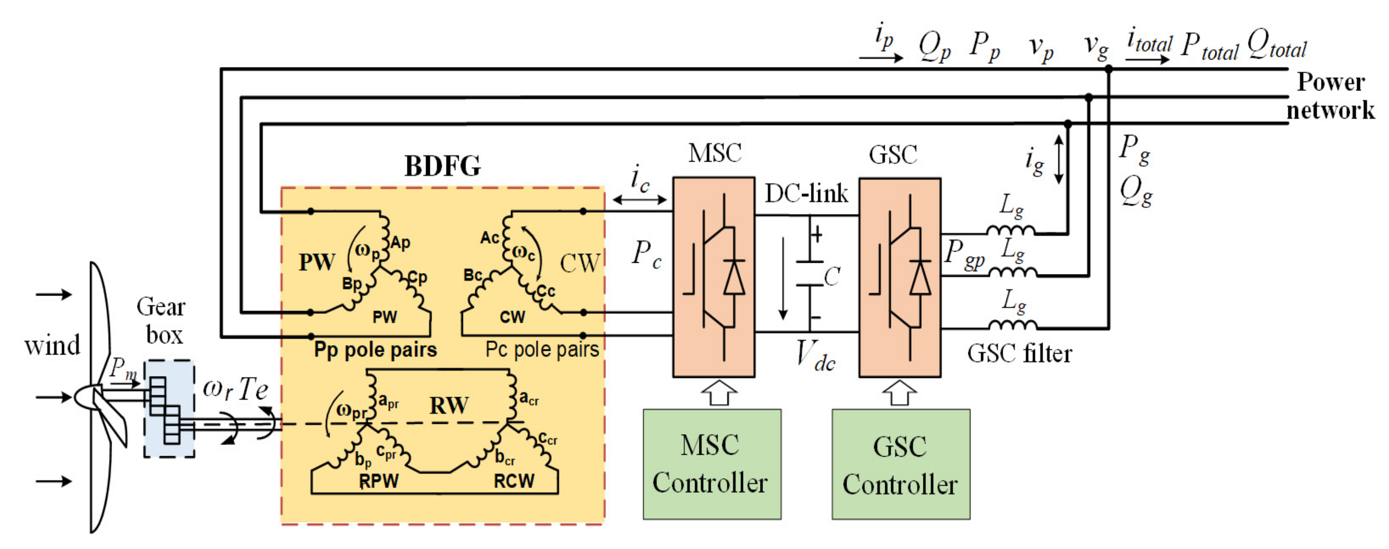
2. Modeling of BDFG (MSC) and GSC in αβ Reference Frame during Grid Voltage Unbalance

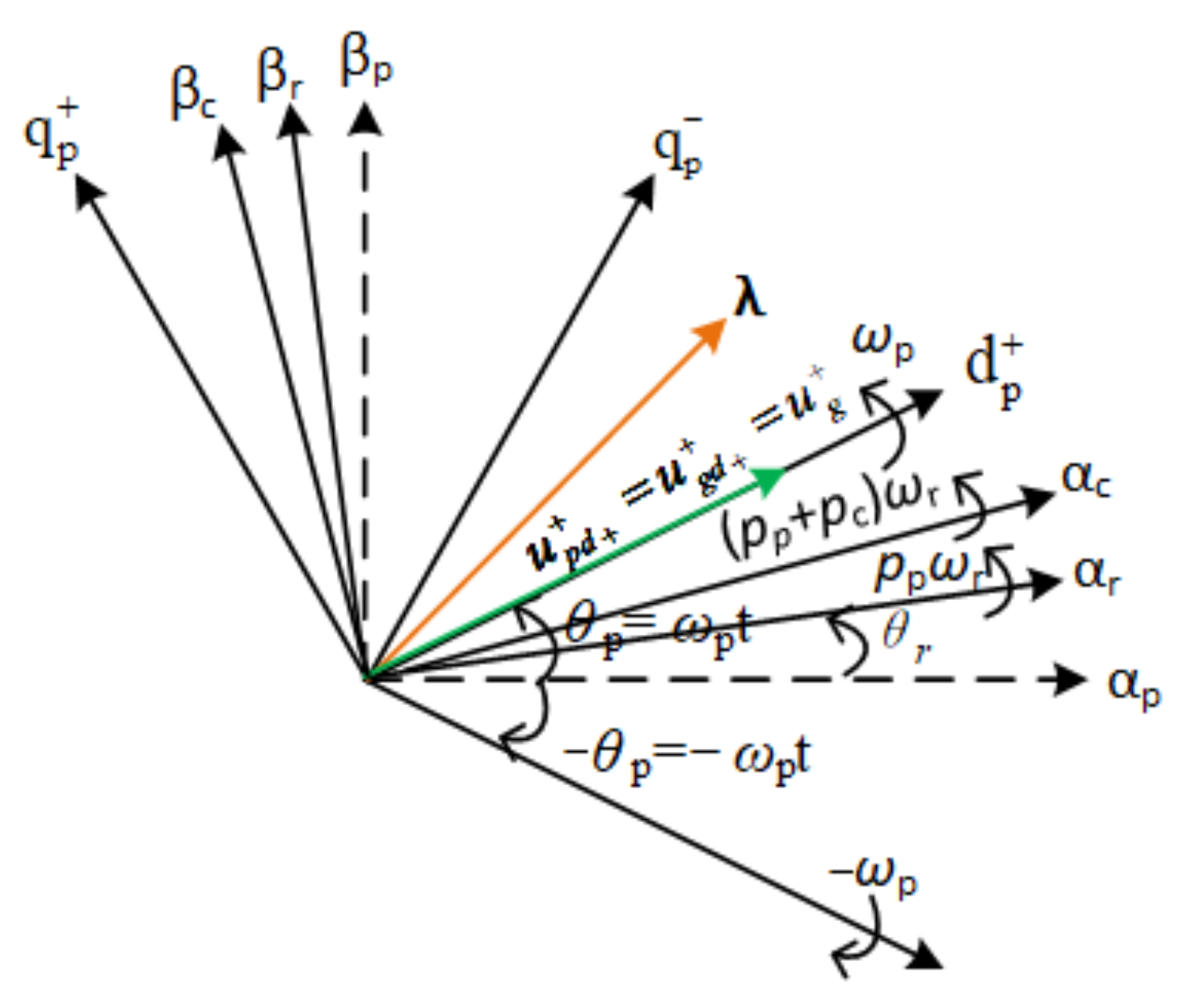
2.1. Modeling of BDFG

During the grid voltage unbalanced condition, the mathematical model of a BDFG in the PW αβ reference frame can be expressed as [4,10,11,14,17,19,21]
u p α β = r p i p α β + d φ p α β d t
u c α β = r c i c α β + d φ c α β d t j ( p p + p c ) ω r φ c α β
u r α β = r r i r α β + d φ r α β d t j p p ω r φ r α β
φ p α β = L p i p α β + L p r i r α β
φ c α β = L c i c α β L c r i r α β
φ r α β = L r i r α β + L p r i p α β L c r i c α β
where upαβ, ucαβ, urαβ, ipαβ, icαβ, irαβ, φpαβ, φcαβ and φrαβ represent voltage, current and flux spatial vectors of PW, CW and RW in the PW αβ reference frame; rp, rc, rr, Lp, Lc and Lr denote resistances and self-inductances of PW, CW and RW; Lpr and Lcr denote mutual inductances between PW and RW and CW and RW; ur = 0, subscripts p, c and r denote PW, CW and RW.
Based on (4), the RW current can be given by
i r α β = φ p α β L p r L p L p r i p α β
By using (7), CW flux (5) and RW flux (6) are written as
φ r α β = L r L p r φ p α β L M i p α β L c r i c α β
φ c α β = L c i c α β L c r L p r φ p α β + L c r L p L p r i p α β
Combining (7) and (8), RW voltage (3) becomes
r r ( φ p α β L p i p α β L p r ) + L r L p r d φ p α β d t L M d i p α β d t L c r d i c α β d t j p p ω r ( L r L p r φ p α β L M i p α β L c r i c α β ) = 0
In (10), LM = (LrLp/Lpr) − Lpr. Combining (9) and (10), CW voltage (2) is given by
u c α β = r c i c α β + σ L c d i c α β d t + K c α β
where σ denotes the leakage factor, expressed as σ = 1 − L2crLp/(LprLMLc) and Kcαβ denotes total cross-couplings and disturbances. It can be written as
K c α β = j ( p p ω r L c r 2 L p L p r L M ( p p + p c ) ω r L c ) i c α β ( j p c ω r L c r L p L p r + r r L p 2 L c r L p r 2 L M ) i p α β + ( j ( p p + p c ) ω r L c r L p r + r r L p L c r L p r 2 L M j p p ω r L c r L p L r L p r 2 L M ) φ p α β + ( L c r L p r + L r L p L c r L p r 2 L M ) ( u p α β r p i p α β )
The spatial relations between BDFG’s αpβp reference frame, the αcβc reference frame rotating at speed (pp + pc)ωr, the αrβr reference frame rotating at speed ppωr, the (dpqp)+ reference frame rotating at speed ωp and the (dpqp) reference frame revolving at speed –ωp can be illustrated as shown in Figure 2.
In the case of grid voltage unbalance, the BDFG quantities are composed of positive and negative sequence components. According to Figure 2, the spatial vectors λ (voltages, currents and fluxes) can be represented as follows:
λ α β = λ α β + + λ α β = λ d q + + e j ω p t + λ d q e j ω p t
In (13), superscripts +, − denote (dpqp)+ and (dpqp) reference frames and subscripts +, − denotes positive and negative sequence components.
Under the grid voltage unbalanced condition, the PW instantaneous active and reactive powers and generator electromagnetic torque can be given by [16,17,18]
P p = P p 0 + P p s 2 sin 2 ω p t + P p c 2 cos 2 ω p t Q p = Q p 0 + Q p s 2 sin 2 ω p t + Q p c 2 cos 2 ω p t T e m = T e m 0 + T e m s 2 sin 2 ω p t + T e m c 2 cos 2 ω p t
In (14), Pp0, Pps2, Ppc2, Qp0, Qps2, Qpc2, Tem0, Tems2 and Temc2 denote the average values and the amplitudes of the pulsations of PW active and reactive powers and the electromagnetic torque, respectively. They are represented as
P p 0 Q p 0 P p s 2 P p c 2 Q p s 2 Q p c 2 = 3 L r 2 L M L p r u p d + + u p q + + u p d u p q u p q + + u p d + + u p q u p d u p q u p d u p q + + u p d + + u p d u p q u p d + + u p q + + u p d u p q u p d + + u p q + + u p q u p d u p q + + u p d + + φ p d + + φ p q + + φ p d φ p q + 3 L c r 2 L M u p d + + u p q + + u p d u p q u p q + + u p d + + u p q u p d u p q u p d u p q + + u p d + + u p d u p q u p d + + u p q + + u p d u p q u p d + + u p q + + u p q u p d u p q + + u p d + + i c d + + i c q + + i c d i c d
T e m 0 T e m s 2 T e m c 2 = µ T e m φ p q + + φ p d + + φ p q φ p d φ p d φ p q φ p d + + φ p q + + φ p q φ p d φ p q + + φ p d + + i c d + + i c q + + i c d i c q
where
µ T e = 3 2 p c L c r L p L r L M L p r 2 p c L c r L p r p p L c r L M

2.2. Modeling of GSC Side

During grid voltage unbalance, the GSC’s mathematical model in the αβ reference frame is given by [22]
u g α β = r g i g α β + L g d i g α β d t + u g p α β
C d V d c d t V d c = P g p P c
where rg and Lg represent the resistance and inductance of the GSC filter; C and Vdc represent the DC-link capacitance and voltage; ugαβ, ugpαβ, Pgp and Pc are the network voltage vector, the GSC pole voltage vector, the GSC pole and the CW active powers which are shown in Figure 1.
Under grid voltage unbalance, the instantaneous output active and reactive powers of GSC are given by [17,18]
P g = P g 0 + P g s 2 sin 2 ω p t + P g c 2 cos 2 ω p t Q g = Q g 0 + Q g s 2 sin 2 ω p t + Q g c 2 cos 2 ω p t
where Pg0, Pgs2, Pgc2, Qg0, Qgs2 and Qgc2 denote the average values and the amplitudes of pulsations of GSC output active and reactive powers, respectively, and can be given as
P g 0 Q gp 0 P g s 2 P g c 2 Q g s 2 Q g c 2 = 2 3 u g d + + u g q + + u g d u g q u g q + + u g d + + u g q u g d u g q u g d u g q + + u g d + + u g d u g q u g d + + u g q + + u g d u g q u g d + + u g q + + u g q u g d u g q + + u g d + + i g d + + i g q + + i g d i g d

3. Proposed Collaborative Control for BDFGWT under Grid Voltage Unbalance

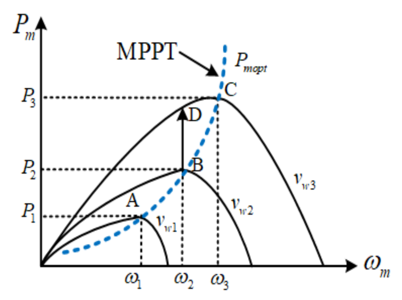
3.1. Characteristics of Wind Turbine and MPPT Control

The characteristic curve of turbine mechanical power Pm versus rotating speed ωm under different wind speed can be seen in Figure 3. As can be observed, at certain wind speed (e.g., vw1, vw2, vw3), turbine mechanical power varies with its rotational speed. The maximal power (e.g., P1, P2, P3) occurs at optimal rotating speed (e.g., ω1, ω2, ω3). Thus, as illustrated in Figure 3, by connecting the maximal power points under different wind speeds, the optimal power curve can be obtained and its mathematical expression can be deduced as [23,24,25]
P m o p t = 0.5 ρ π R 5 C P max λ o p t 3 ω m 3 = k o p t ω m 3
where ρ and R represent the air density; turbine radius—kopt = 0.5ρπR5Cpmax/λopt3; Pmopt, Cpmax and λopt represent the maximum output mechanical power, maximal power coefficient and optimal tip–speed ratio, respectively.
As indicated in (22), for the purpose of capturing maximal wind energy and output maximal mechanical power at certain wind speed, wind turbine has to be operated at optimal rotating speed. Thus, when wind speed varies, the BDFG’s output power should be controlled accordingly so as to regulate the rotational speed to cause the wind turbine to keep the optimal tip–speed ratio. In addition, in a practical wind generation system, there are power losses during energy transmission. As a result, to realize MPPT control, the control reference of the PW active power can be deduced as
P p 0 * = k o p t ω m 3 η ( 1 s ) = k o p t ω r 3 η ( 1 s ) N 3
where η and s represent the system transfer efficiency and the slip rate of BDFG, respectively.

3.2. Collaborative Control Objectives for MSC and GSC

3.2.1. MSC(BDFG) Side

According to (13)~(16), under the grid voltage unbalanced condition, there exist unbalance in PW currents, distortion in CW currents, pulsations in the PW powers and electromagnetic torque. Hence, there are various control objectives for the MSC side which is able to be selected such as eliminating the unbalance or distortion of currents and the pulsations in powers or torque. Usually, eliminating the pulsation of the electromagnetic torque is designated as the control objective for the MSC side. Thus, in order to achieve such control objective, substituting the references of the PW active and reactive powers ( P p 0 and Q p 0 ) into (15) and Tems2 = 0 and Temc2 = 0 into (16) and using the grid-voltage-oriented method shown in Figure 2, i.e., u p d + + = u g d + + = u g + , u p q + + = u g q + + = 0 , the MSC(CW) current control references are computed as in [17].
i c d + + = 2 L M u p d + + P p 0 3 L c r u p d + + 2 + u p d 2 + u p q 2 i c q + + = 2 L M u p d + + Q p 0 3 L c r u p d + + 2 u p d 2 u p q 2 L r u p d + + L p r L c r ω p i c d = u p d u p d + + i c d + + + u p q u p d + + i c q + + i c q = u p q u p d + + i c d + + u p d u p d + + i c q + +
Additionally, it is worth noting that if eliminating the pulsations of Qp is selected as the control objective for the MSC side, the MSC(CW) current control references are the same as in (24). Thus, the pulsations of Tem and Qp are capable of being eliminated at the same time.

3.2.2. GSC Side

As analyzed in Section 2.1 and Section 2.2, during grid voltage unbalance, the negative components in network voltage lead to unbalance and pulsations in output currents, active and reactive powers of both the PW side and the GSC side. Thus, according to Figure 1, there exists unbalance in the total output current Itotal, as well as pulsations in total output active and reactive powers (Ptotal and Qtotal) if MSC and GSC are not controlled properly. Such total current unbalance and power pulsations are very harmful to the power system and even lead to its instability. As a consequence, many system operators have revised the rules requiring the BDFGWT to be capable of resisting a certain grid unbalance. For the purpose of satisfying the requirements, the control objectives for the whole BDFGWT system should be set as canceling the unbalance in total output currents, canceling the pulsations in Ptotal or Qtotal. However, all the MSC control variables are used to cancel torque pulsations; therefore, the GSC current components, namely, i g d + + , i g q + + , i g d and i g q , are capable of being used to achieve collaborative control with MSC so as to attain the control objectives of the whole BDFGWT system. To sum up, GSC can be used to achieve the following collaborative control objectives [17]:
Control objective (1) Keeping the balance of BDFGWT’s total output current Itotal, i.e., I t o t a l d = I t o t a l q =0. In this case, Itotal is balanced and the GSC current control references are computed as
i g d + + = 2 P g 0 3 u g d + + + u g d u g d + + i pd + u g q u g d + + i pq i g q + + = 2 Q g 0 3 u g d + + u g q u g d + + i pd + u g d u g d + + i pq i g d = i pd i g q = i pq
Control objective (2) Canceling the pulsations of BDFGWT’s total output active power Ptotal, namely Ptotals2 = 0 and Ptotalc2 = 0. In this case, the GSC current references are computed as
i g d + + = 2 ( u g d + + P g 0 + u g d P p c 2 + u g q P p s 2 ) 3 ( u g d + + 2 u g d 2 u g q 2 ) i g q + + = 2 ( u g d + + Q g 0 u g d P p s 2 + u g q P p s 2 ) 3 ( u g d + + 2 + u g d 2 + u g q 2 ) i g d + = 2 P p c 2 3 u g d + + u g d u g d + + i g d + + u g q u g d + + i g q + + i g q + = 2 P p s 2 3 u g d + + u g q u g d + + i g d + + + u g d u g d + + i g q + +
Control objective (3) Canceling pulsations of BDFGWT’s total reactive power Qtotal, namely, Qtotals2 = 0 and Qtotalc2 = 0. In such case, the GSC current references are computed as
i g d + + = 2 u g d + + P g 0 3 u g d + + 2 + u g d 2 + u g q 2 i g q + + = 2 u g d + + Q g 0 3 u g d + + 2 u g d 2 u g q 2 i g d = u g d u g d + + i g d + + + u g q u g d + + i g q + + i g q = u g q u g d + + i g d + + u g d u g d + + i g q + +

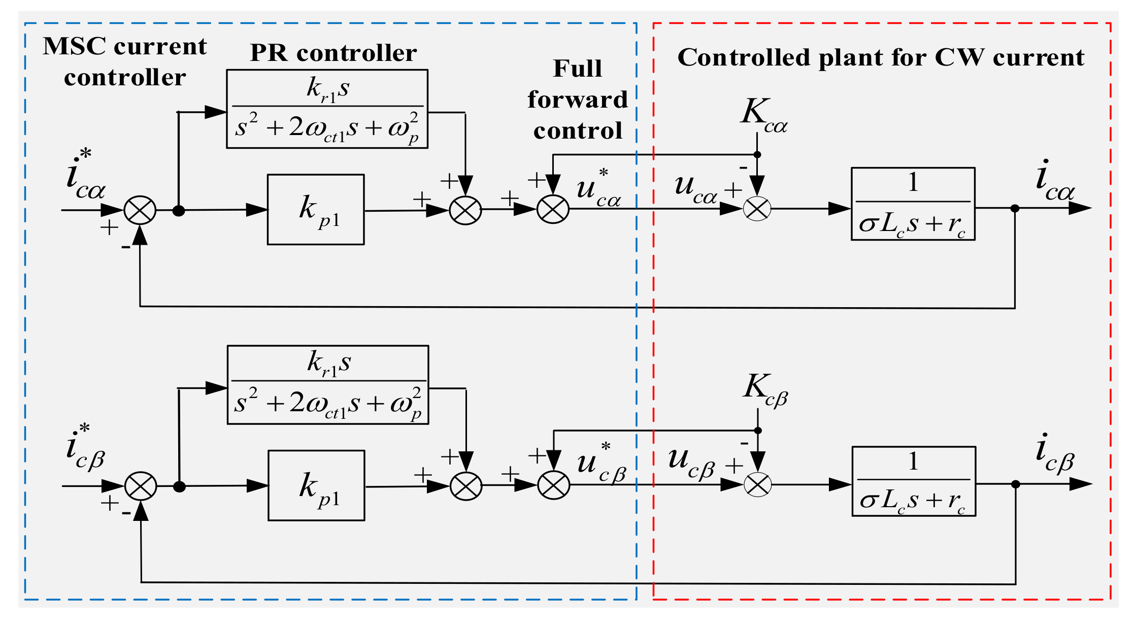
3.3. Proposed PR Current Controller Design for MSC and GSC

On the basis of (24)–(27), the MSC and GSC current control references can be determined so as to realize the corresponding control objectives of MSC (BDFG) and GSC. Thus, for the sake of making the measured MSC and GSC currents track with their current references, the current controllers need to be employed. Usually, dual PI controllers composed of positive plus negative sequence current controllers are used for MSC and GSC, in which the sequence extractions for MSC and GSC currents are required [12,14,15,17,18]. However, multiple uses of the sequence extraction algorithm can make the control system much more complex. Moreover, the sequence extractions are capable of introducing considerable phase and amplitude errors to MSC and GSC currents, hence deteriorating their dynamic characteristics. To overcome the above problems, in this paper, improved MSC and GSC current controllers adopting PR regulators are proposed to control MSC and GSC currents to follow the references during grid voltage unbalance, which are analyzed in the following.

3.3.1. PR Current Controller Design for MSC

During the grid voltage unbalanced condition, as expressed in (13), the MSC(CW) current vector in the PW αβ reference frame includes a positive sequence (+ωp AC value) and negative sequence (−ωp AC value). Based on the knowledge of control theory, for the sake of eliminating steady state errors of AC variables, only a PR regulator at a resonant frequency of ωp is capable of being used to regulate the positive and the negative sequences with frequencies of ωp and −ωp at the same time. As a result, under the grid voltage unbalanced condition, the PR regulator is capable of being used to control the CW current whose sequence extraction is not needed any more.
Consequently, according to (11) and (12), the CW (MSC) current controllers with PR regulators on PW αβ axes are designed as
u c α = k p 1 + k r 1 s s 2 + 2 ω c t 1 s + ω p 2 ( i c α i c α ) + K c α
u c β = k p 1 + k r 1 s s 2 + 2 ω c t 1 s + ω p 2 ( i c β i c β ) + K c β
where kp1 and kr1 represent the proportional and resonant coefficients of the PR regulator, ωct1 denotes the cut-off frequency of the PR regulator, u c α and u c β denote the referenced CW voltages, and K and K denote the feedforward control terms shown in (12).
Based on (11), (28) and (29), Figure 4 illustrates the proposed PR current controller for MSC. In order to attenuated the high-frequency harmonics and also guarantee the control performances, the closed-loop bandwidth of the MSC current controller can be slightly less than or approximately equal to one-tenth of the switching frequency of MSC. Thus, on the basis of Figure 4, when the switching frequency of MSC is 2 kHz, the Bode plots of the closed-loop transfer function can be illustrated as in Figure 5, where Kp1 =0.8, Kr1 = 100 and ωct1 = 1.5 rad/s. According to Figure 5, the proposed current controller nearly does not have amplitude and phase errors for the signal at the ωp (100 π rad/s, 50 Hz) frequency. Moreover, under the condition of the above parameters, the Bode plots for its opened-loop transfer function are illustrated as in Figure 6. According to Figure 6, the phase margin and the gain margin are 80.5° and infinity, respectively. As a result, the proposed MSC current controller with PR regulators has very good stability and high control precision.

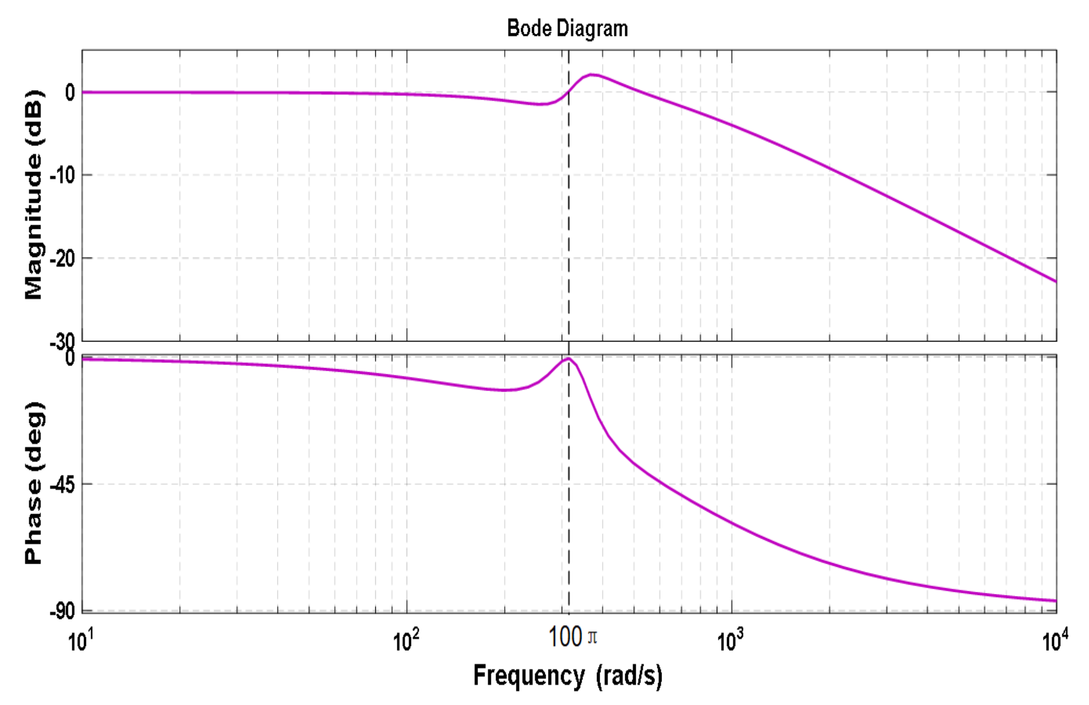
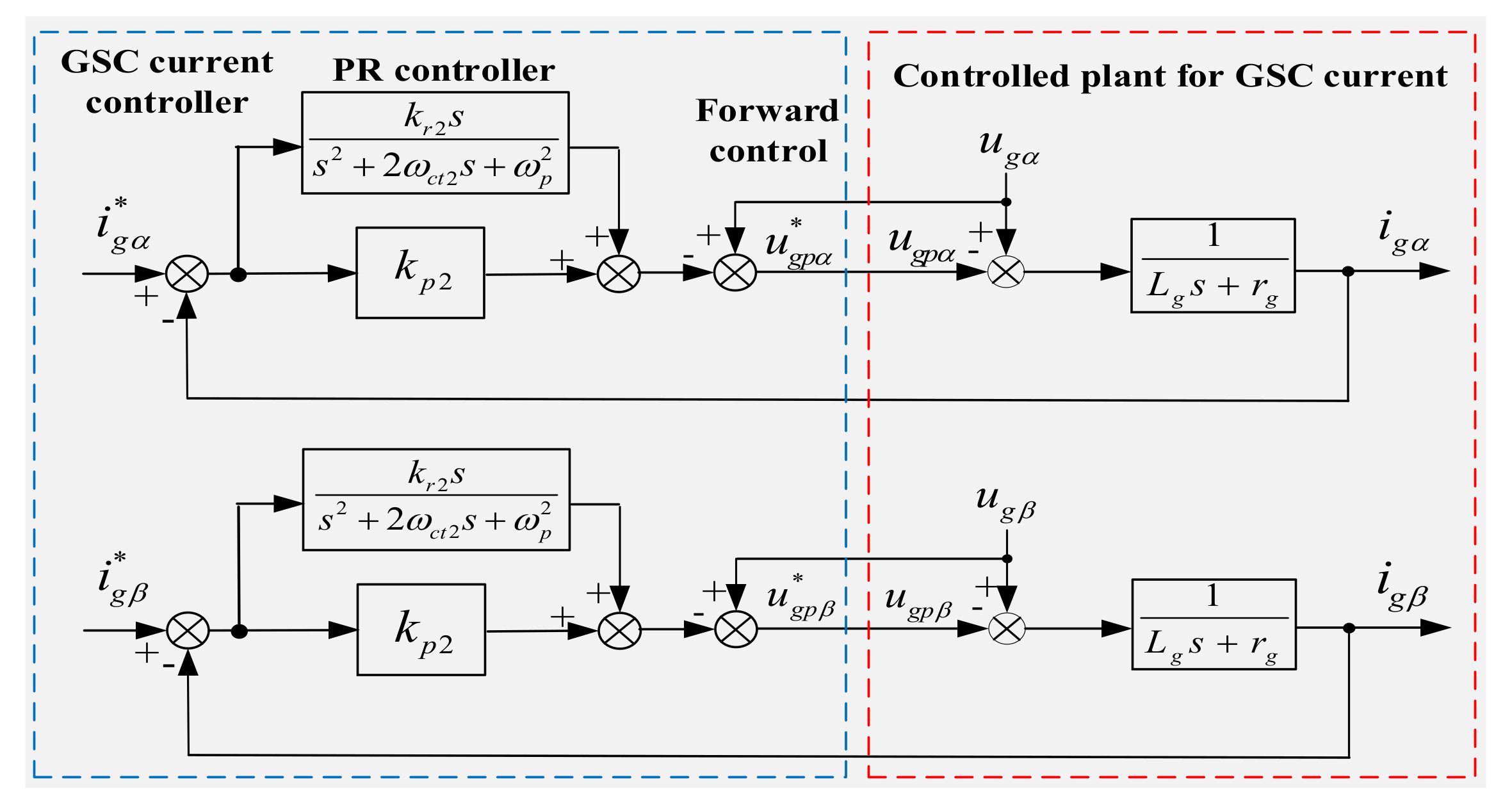
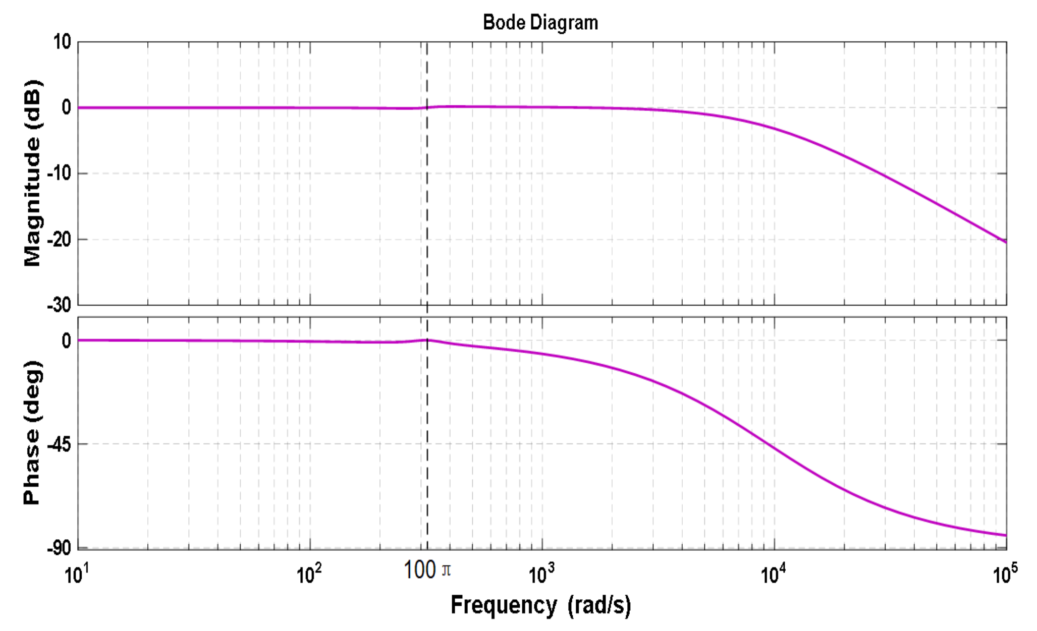
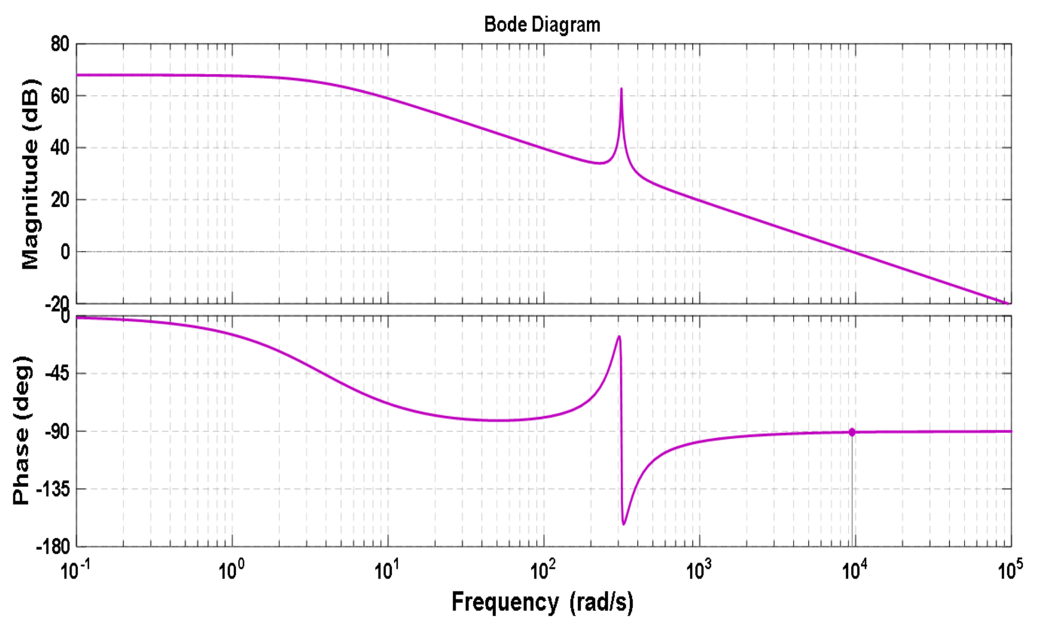
3.3.2. PR Current Controller Design for GSC

As analyzed in Section 3.2.2, GSC is controlled to realize the collaborative control objectives and according to (25)–(27), the required GSC current control references can be determined. To track the references, a current controller needs to be employed. Similarly, according to (18), the GSC current under unbalanced grid voltage is also composed of a positive sequence (+ωp AC value) and a negative sequence (−ωp AC value). Thus, similar to MSC, a PR controller at a resonant frequency of ωp is also capable of being used to precisely regulate the GSC current without the need for sequence extraction.
Consequently, according to (18), the GSC current controllers with PR regulators on αβ axes are designed as
u g p α = k p 2 + k r 2 s s 2 + 2 ω c t 2 s + ω p 2 ( i g α i g α ) + u g α
u g p β = k p 2 + k r 2 s s 2 + 2 ω c t 2 s + ω p 2 ( i g β i g β ) + u g β
where kp2, kr2 represent the proportional and resonant coefficients of the GSC PR regulator, ωct2 denotes the cut-off frequency of the PR regulator, u g p α , u g p β represent the control references of GSC pole voltages on α and β axes, and u and u are the feedforward control terms.
Based on (30) and (31), Figure 7 illustrates the proposed PR current controller for GSC. For the GSC current controller, fast response speed is required, and high-frequency harmonics also need to be attenuated. The closed-loop bandwidth of the GSC current controller can be selected as approximately one-fifth of the switching frequency. Thus, on the basis of Figure 7, when the switching frequency of GSC is 3.5 kHz, the Bode plots of a closed-loop transfer function can be illustrated as in Figure 8, where kp2 =1.5, kr2 = 200 and ωct2 = 2 rad/s.
Similarly, according to Figure 8, the proposed current controller nearly does not have the amplitude and phase errors for the signal at the ωp (100 π rad/s, 50 Hz) frequency, either. The Bode plots of the opened-loop transfer function are illustrated in Figure 9. As illustrated, the gain and phase margins are infinity and 90°, respectively. As a result, the proposed GSC current controller with PR regulators also has very good stability and high control precision.

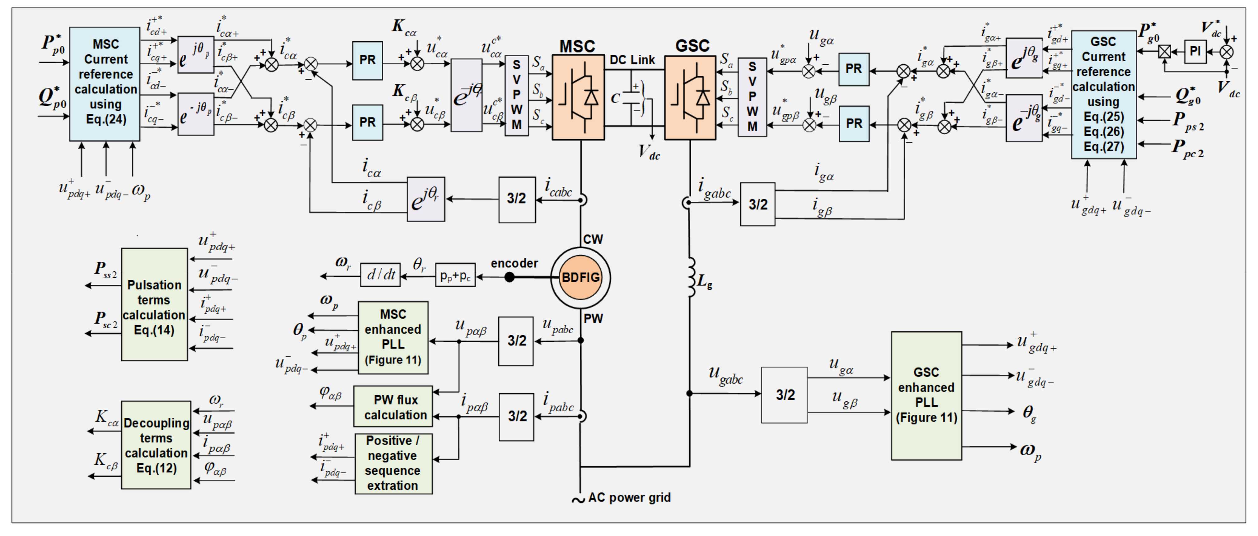
3.4. Implementation of Proposed Collaborative Control Scheme

Based on previous analysis, the proposed overall collaborative control scheme for a BDFGWT under grid voltage unbalance is illustrated in Figure 10. As illustrated, for the MSC side, its current references are calculated by (24). Moreover, by using 3/2 plus αcβc/αpβp transformations, the measured CW current is converted into the αpβp reference frame. There is obviously no need for sequence extraction. Then, compared with the references, the errors are controlled by PR regulators. Afterwards, through αpβp/αcβc transformations and space vector pulse width modulation (SVPWM), the driving pulses for MSC are produced. For the GSC side, the current references under different control objectives are calculated by (25)–(27). After 3/2 transformation, the measured GSC current is converted into the αβ reference frame and there is also no need for sequence extraction. Then, the references and the errors are controlled by PR regulators. Afterwards, through SVPWM modulation, the driving pulses for GSC are produced. In addition, in Figure 10, in order to calculate the references of MSC and GSC currents, the sequence components of grid voltage need to be decomposed. Moreover, the position angle of the grid voltage vector (θp, θg) needs to be estimated by a phase-locked loop (PLL). The fast decomposition method in [16,17,18] has very good performance; therefore, it is adopted in the proposed control. By using this algorithm, the sequence components can quickly and precisely decompose during unbalanced grid voltage. The block diagram of the enhanced PLL based on such extraction method is shown in Figure 11, where γ and ω denote signal frequency and the decomposition time interval, respectively.
According to Figure 4, Figure 7 and Figure 10, it is worth noting that due to the uses of PR regulators, the sequence extractions for both MSC and GSC currents are not needed any more. However, in existing controls, the sequence extractions for MSC and GSC currents are necessary. Hence, compared to existing controls, the proposed control structure is much simpler, and dynamic performance is also improved. Moreover, in order to achieve the decoupling control of the current and the average power, the current controller also adopts a feedforward control approach considering all the couplings and perturbances. In addition, according to (11), (18), Figure 4, Figure 7 and Figure 10, the control capability of the proposed scheme is physically restricted by the maximum output voltage and the current of MSC and GSC. Usually, the maximum output voltages of MSC and GSC are limited by DC-link voltage and the maximum output currents are equal to twice of their rated currents, i.e., 2.0 p.u., respectively. Thus, when the permitted maximum currents are relatively higher, the proposed control can have better control capability to resist bigger grid voltage unbalance.

4. Results and Discussion

For the sake of validating the effectiveness of the proposed control scheme, case studies for a two MW BDFGWT system under grid voltage unbalance were implemented with Matlab–Simulink. The system parameters are shown in Table A1 and Table A2 in Appendix A. Grid voltage unbalance is usually caused by factors such as unbalanced load and asymmetrical faults in the network. Figure 12 illustrates the waveforms of grid voltage under 8.5% unbalance and 9.5% unbalance, respectively. Moreover, the wind turbine can operate in static and dynamic states where the wind speeds are invariable and variable. Invariable wind speed leads to constant rotor speed of a BDFG, and variable wind speed leads to variable rotor speed. Figure 13A illustrates the waveform of constant rotor speed caused by invariable wind speed. As illustrated, when the input wind speed is 5.8 m/s, the rotor speed is also invariable and approximately equal to 0.8 p.u. Figure 13B illustrates the waveform of variable rotor speed caused by variable wind speed. As can be seen, the initial wind speed is 5 m/s and the rotor speed is 0.7 p.u.; when the input wind speed is step-changed from 5 m/s to 8 m/s at 0.5 s, the rotor speed is changed from 0.7 p.u. at 0.5 s to 1.1 p.u. at 1.1 s.
Figure 14 illustrates the results in the case of constant rotor speed (0.8 p.u.) caused by invariable wind speed and 8.5% grid unbalance in which traditional vector control without consideration of network unbalance and the proposed control are compared. For GSC, the reference of DC-link voltage is set as 1200 V and the GSC reactive power reference Q g 0 * is 0 MVar while for MSC, P p 0 and Q p 0 are 1.0 pu and 0 MVar. In the proposed control, the control objective analyzed in Section 3.2.1 and three selectable control objectives in Section 3.2.2 are set for MSC and GSC, respectively. GSC’s control objective was initially set as Control objective (1); afterwards, it was set as Control objective (2) at 0.2 s and finally changed to Control objective (3) at 0.4 s. Figure 14A illustrates the waveforms using traditional vector control without considering grid voltage unbalance. According to Figure 14A(a), there are large unbalances in Itotal since the sequence components of MSC and GSC currents are not controlled separately in traditional vector control. This is also indicated in Figure 14A(g,i), where the dq currents of MSC and GSC all contain 100 Hz pulsated components. Moreover, according to Figure 14A(b,d,f), these unbalanced currents also result in very large 100 Hz pulsations in Ptotal, Qtotal and Te. Such unbalances and pulsations are very harmful to a BDFGWT and the power system, even resulting in the damages of a generator’s mechanical and electrical parts and the instability of the power system. Figure 14(B) illustrates the results under the proposed control. According to Figure 14B(a,b,d), from 0 s to 0.2 s, total currents Itotal keep balance; when Control objective (2) is selected from 0.2 s to 0.4 s, the pulsations in Ptotal cancel out; finally, when Control objective (3) is applied from 0.4 s to 0.6 s, the pulsations in Qtotal are eliminated. Furthermore, as shown in Figure 14B(e,f), there are no pulsations in Te and Qp all the time. In addition, as illustrated in Figure 14B(g,i), i c α , i c β , i g α , i g β , i c α , i c β , i g α and i g β are all the 50 Hz AC value and i c α , i c β , i g α and i g β follow their references i c α , i c β , i g α and i g β very well. This is attributes to the proposed PR current controllers for MSC and GSC. Additionally, as illustrated in Figure 14B(c,e), the actual average values of Pp and Qp are 1.0 pu and 0 MVar; they also track their references very well. According to the simulation results, Table 1 compares the unbalance in Itotal, distortion in Ic (105 Hz harmonic, 5 Hz fundamental component), 100 Hz pulsations in Ptotal, Qtotal and Te under different control objectives. It is evident that the values in Table 1 conform to the results illustrated in Figure 14. As a result, the proposed control is capable of effectively suppressing or canceling the unbalance in the currents, pulsations of power, torque and DC-link voltage when compared with traditional vector control. Also, the control objectives set for MSC together with GSC are fully achieved, respectively.
Further study in the case of variable rotor speed caused by variable wind speed is also carried out by adopting the proposed control. P p 0 is computed with the MPPT curve, Q p 0 is initially set as −0.25 p.u. (capacitive reactive power) and abruptly changed from −0.25 p.u. (capacitive) to 0.25 p.u. (inductive) at 1.7 s. The step change in wind speed from 5 m/s to 8 m/s at 0.5 s leads to the variation of rotor rotary speed from sub-synchronous operation (0.7 p.u.) to super-synchronous operation (approximately 1.1 p.u.). The grid voltage unbalance is 9.5%. Figure 15A,B show the results under traditional vector control without considering grid voltage unbalance and the proposed control separately. In Figure 15B, as analyzed in Section 3.2, eliminating torque pulsations is selected for the MSC side all the time, while for GSC, the control objective is initially set as Control objective (1).; afterwards, at 0.2 s, it is set as Control objective (2); finally, at 1.5 s, Control objective (3) is set. As can be seen from Figure 15A(a,b), very large unbalance and distortion appear in total output currents and CW currents. Additionally, according to Figure 15A(d,f,g,h), Ptotal, Qtotal, Qp and Te exist with very large 100 Hz pulsations all the time. In comparison, according to Figure 15B(a,d,f), from 0 to 0.2 s, Itotal is balanced; afterwards, from 0.2–1.5 s, the pulsations of total output active power Ptotal are eliminated. Also, when Control objective (3) is selected at 1.5 s, the pulsations in total output reactive power Qtotal are canceled. Additionally, according to Figure 15B(g,h), the pulsations in Te and Qp are also canceled as expected. Furthermore, as illustrated in Figure 15B(e,g), the controls for Pp and Qp are decoupled and have satisfactory dynamic performances. Consequently, compared with traditional vector controls, the proposed control is capable of greatly improving the capability of resisting grid voltage unbalance for a BDFGWT system.

5. Conclusions

This article presents an improved collaborative control to resist grid voltage unbalance for a BDFGWT system. Compared with existing controls, the contributions and distinctions of this article can be summarized as follows:
(1)
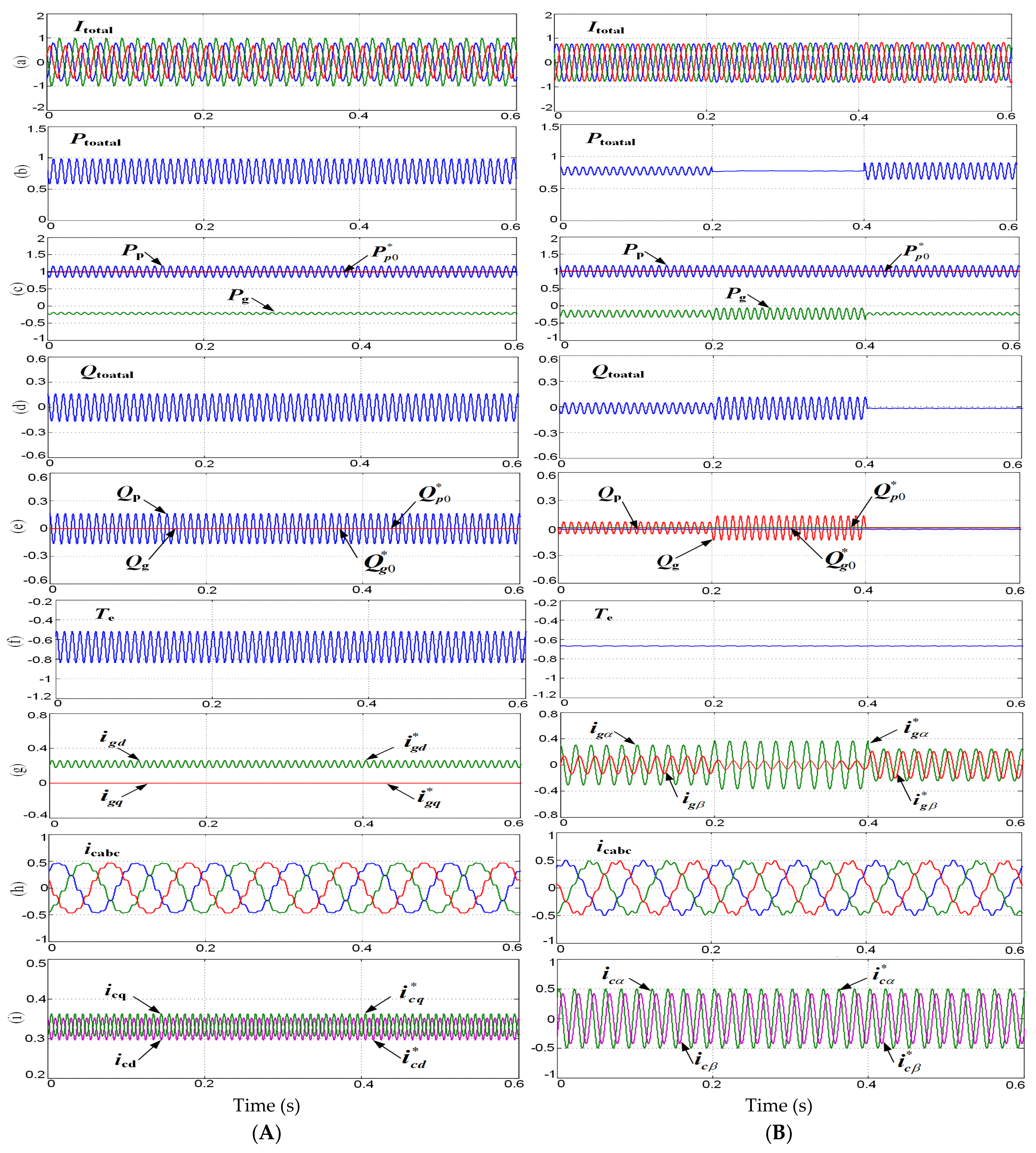
The mathematical model of a grid-connected BDFG including MSC and GSC in the αβ reference frame during the unbalanced grid voltage condition is established.
(2)
An improved collaborative control between MSC and GSC is presented, where the MPPT control for a BDFGWT is also included. Under the control, the control objective of a whole BDFGWT system, including canceling the pulsations of the electromagnetic torque and the unbalance of BDFGWT’s total currents, is the fact that pulsations of BDFGWT’s total powers are capable of being realized. Therefore, the control capability of a BDFGWT to resist unbalanced grid voltage is greatly improved.
(3)
Improved single-loop current controllers adopting PR regulators are proposed for both MSC and GSC, where the sequence extractions for both MSC and GSC currents are not needed any more, and hence the proposed control is much simpler and the transient characteristics are also improved. Moreover, in order to achieve the decoupling control of the current and the average power, the current controller also adopts a feedforward control approach by considering all the couplings and perturbances.
The results of case studies verify that the presented control is capable of effectively achieving the control objectives of a whole BDFGWT system during grid voltage unbalance and exhibits good stable and dynamic control performances. In future work, the characteristics of the wind farm equipped with a BDFGWT under grid voltage unbalance will be studied.

Author Contributions

Conceptualization, D.C. and S.H.; methodology, D.C. and S.H.; validation, R.C. and S.H.; formal analysis, G.S.; investigation, E.W.; writing—original draft preparation, S.H.; writing—review and editing, S.H.; supervision, D.C. and J.T.; project administration, D.C. and J.T. All authors have read and agreed to the published version of the manuscript.

Funding

This work was funded by the Guideline Project of State Grid Corporation of China, grant number 5100-202199536A-0-5-ZN.

Data Availability Statement

The data presented in this study are available in the article.

Conflicts of Interest

Authors Defu Cai, Rusi Chen, Guanqun Sun and Erxi Wang were employed by the company State Grid Hubei Electric Power Research Institute. The remaining authors declare that the research was conducted in the absence of any commercial or financial relationships that could be construed as a potential conflict of interest.

Appendix A

Table A1. Parameters of BDFG and converter.
ParametersValues
Nominal power (MW)2 MW
Nominal voltage (V)690 V
Nominal frequency (Hz)50 Hz
rp, rc, rr (Ω)0.0012, 0.0072, 0.0010
Lp, Lc, Lr (mH)3.1000, 6.8890, 19.050
Lpr, Lcr (mH)6.6560, 4.8940
Pole pairs (pp, pc)2, 2
rg (Ω)3.1000
Lg (mH)0.18
C (uF)2000
Table A2. Parameters of wind turbine and gear box.
ParametersValues
Nominal power (MW)2 MW
Turbine diameter93.4 m
Cut-in wind speed3 m/s
Nominal wind speed10.5 m/s
Gear ratio59
System inertia60 Kg·m2
Friction coefficient0.007

References

  1. Loukianov, A.; Huerta, H. Energy based sliding mode control of brushless double-fed induction generator. Int. J. Electr. Power Energy Syst. 2021, 130, 107002. [Google Scholar]
  2. Strous Tim, D.; Polinder, H.; Ferreira, J.A. Brushless doubly-fed induction machines for wind turbines: Developments and research challenges. IET Electr. Power Appl. 2017, 11, 991–1000. [Google Scholar] [CrossRef]
  3. Gowaid, I.A.; Abdel-Khalik, A.S.; Massoud, A.M.; Ahmed, S. Ride through capability of grid-connected brushless cascade DFIG wind turbines in faulty grid conditions—A comparative study. IEEE Trans. Sustain. Energy 2013, 4, 1002–1015. [Google Scholar] [CrossRef]
  4. Long, T.; Shao, S.; Abdi, E.; McMahon, R. Asymmetrical low-voltage ride through of brushless doubly fed induction generators for the wind power generation. IEEE Trans. Energy Conv. 2013, 28, 502–511. [Google Scholar] [CrossRef]
  5. Cheng, M.; Jiang, Y.; Han, P.; Wang, Q. Unbalanced and low-order harmonic voltage mitigation of stand-alone dual-stator brushless doubly fed induction wind generator. IEEE Trans. Ind. Electron. 2018, 65, 9135–9146. [Google Scholar] [CrossRef]
  6. Xu, W.; Mohammed, O.M.; Liu, Y.; Islam, M.R. Negative sequence voltage compensating for unbalanced standalone brushless doubly-fed induction generator. IEEE Trans. Power Electron. 2020, 35, 667–680. [Google Scholar] [CrossRef]
  7. Liu, Y.; Xu, W.; Zhu, J.; Blaabjerg, F. Sensorless control of standalone brushless doubly fed induction generator feeding unbalanced loads in a ship shaft power generation system. IEEE Trans. Ind. Electron. 2019, 66, 739–749. [Google Scholar] [CrossRef]
  8. Liu, Y.; Xu, W.; Long, T.; Blaabjerg, F. An improved rotor speed observer for standalone brushless doubly-fed induction generator under unbalanced and nonlinear Loads. IEEE Trans. Power Electron. 2020, 35, 775–788. [Google Scholar] [CrossRef]
  9. Shao, S.; Abdi, E.; Barati, F.; McMahon, R. Stator-flux-oriented vector control for brushless doubly fed induction generator. IEEE Trans. Ind. Electron. 2009, 56, 4220–4228. [Google Scholar] [CrossRef]
  10. Protsenko, K.; Xu, D. Modeling and control of brushless doubly-fed induction generators in wind energy applications. IEEE Trans. Power Electron. 2008, 23, 1191–1197. [Google Scholar] [CrossRef]
  11. Basic, D.; Zhu, J.G.; Boardman, G. Transient performance study of a brushless doubly fed twin stator induction generator. IEEE Trans. Energy Conv. 2003, 18, 400–408. [Google Scholar] [CrossRef]
  12. Shao, S.; Long, T. Dynamic control of the brushless doubly fed induction generator under unbalanced operation. IEEE Trans. Ind. Electron. 2013, 60, 2465–2476. [Google Scholar] [CrossRef]
  13. Chen, J.; Zhang, W.; Chen, B.; Ma, Y. Improved vector control of brushless doubly fed induction generator under unbalanced grid conditions for offshore wind power generation. IEEE Trans. Energy Conv. 2016, 31, 293–303. [Google Scholar] [CrossRef]
  14. Xu, L.; Cheng, M.; Wei, X.; Yan, X.; Zeng, Y. Dual synchronous rotating frame current control of brushless doubly fed induction generator under unbalanced network. IEEE Trans. Ind. Electron. 2021, 36, 6712–6724. [Google Scholar] [CrossRef]
  15. Taufik, T.; Leposava, R.; Milutin, J. Dynamic Modeling and Control of BDFRG under Unbalanced Grid Conditions. Energies 2021, 14, 4297. [Google Scholar] [CrossRef]
  16. Cai, D.; Liu, H.; Hu, S.; Sun, J.; Wang, H.; Tang, J. A Proportional-Integral-Resonant Current Control Strategy for a Wind-Driven Brushless Doubly Fed Generator during Network Unbalance. Electronics 2024, 13, 1616. [Google Scholar] [CrossRef]
  17. Hu, S.; Zhu, G.; Kang, Y. Modeling and coordinated control design for brushless doubly-fed induction generator based wind turbine to withstand grid voltage unbalance. IEEE Access 2021, 36, 63331–63344. [Google Scholar] [CrossRef]
  18. Hu, S.; Zhu, G. Enhanced control and operation for brushless doubly-fed induction generator basedwind turbine system under grid voltage unbalance. Electr. Power Syst. Res. 2022, 207, 117861. [Google Scholar] [CrossRef]
  19. Han, P.; Cheng, M.; Wei, X.; Li, N. Modeling and performance analysis of a dual-stator brushless doubly fed induction machine based on spiral vector theory. IEEE Trans. Ind. Appl. 2016, 52, 1380–1389. [Google Scholar] [CrossRef]
  20. Poza, J.; Oyarbide, E.; Sarasola, I.; Rodriguez, M. Vector control design and experimental evaluation for the brushless doubly fed machine. IET Electr. Power Appl. 2009, 3, 247–256. [Google Scholar] [CrossRef]
  21. Zeng, Y.; Cheng, M.; Wei, X.; Xu, L. Dynamic modeling and performance analysis with iron saturation for dual-stator brushless doubly fed induction generator. IEEE Trans. Energy Conv. 2020, 35, 260–270. [Google Scholar] [CrossRef]
  22. Li, Z.; Li, Y.; Wang, P.; Zhu, H.; Liu, C.; Xu, W. Control of three-phase boost-type PWM rectifier in stationary frame under unbalanced input voltage. IEEE Trans. Power Electron. 2010, 25, 2521–2530. [Google Scholar] [CrossRef]
  23. Xue, X.; Huang, J.; Sang, S. Innovative Inertial Response Imitation and Rotor Speed Recovery Control Scheme for a DFIG. Electronics 2023, 12, 1029. [Google Scholar] [CrossRef]
  24. Chakraborty, A.; Maity, T. A novel application of adaptive filtering algorithm for LVRT capability enhancement of grid-connected DFIG-based wind energy conversion systems (WECS). Electr. Power Syst. Res. 2023, 217, 109179. [Google Scholar] [CrossRef]
  25. Chemg, M.; Zhu, Y. The state of the art of wind energy conversion systems and technologies: A review. Energy Conv. Manag. 2014, 88, 332–347. [Google Scholar] [CrossRef]
Figure 1. Topology of grid-connected BDFGWT.
Electronics 13 03582 g001
Figure 2. Spatial relations between reference frames of (αpβp), (αr βr), (αcβc), (dq)+ and (dq)−.
Electronics 13 03582 g002
Figure 3. Power characteristic versus rotating speed under different wind speeds.
Electronics 13 03582 g003
Figure 4. Proposed MSC(CW) PR current controller.
Electronics 13 03582 g004
Figure 5. Bode plots for MSC current closed-loop transfer function.
Electronics 13 03582 g005
Figure 6. Bode plots of MSC(CW) current opened-loop transfer function.
Electronics 13 03582 g006
Figure 7. Proposed PR controller for GSC current.
Electronics 13 03582 g007
Figure 8. Bode plots of closed-loop transfer function for GSC current.
Electronics 13 03582 g008
Figure 9. Bode plots of GSC current opened-loop transfer function.
Electronics 13 03582 g009
Figure 10. Proposed overall collaborative control scheme for BDFGWT.
Electronics 13 03582 g010
Figure 11. Fast decomposition algorithm and enhanced PLL for BDFGWT.
Electronics 13 03582 g011
Figure 12. Waveforms of unbalanced grid voltage: (a) 8.5% unbalance (p.u.); (b) 9.5% unbalance (p.u.).
Electronics 13 03582 g012
Figure 13. Waveforms of wind speed and BDFG’s rotor speed. (a) Wind speed (m/s). (b) Rotor speed (p.u.). (A) Invariable wind speed and rotor speed. (B) Variable wind speed and rotor speed.
Electronics 13 03582 g013
Figure 14. Waveforms for BDFGWT system with traditional vector control and proposed control under 8.5% stable network unbalance (ωr = 0.8 p.u.). (a) Total currents (p.u.). (b) Total active power (p.u.). (c) Active powers of PW and GSC (p.u.). (d) Total reactive power (p.u.). (e) Reactive powers of PW and GSC (p.u.). (f) Electromagnetic torque (p.u.). (g) GSC current under dq and αpβp reference frames (p.u.). (h) CW current (p.u.). (i) CW currents in dq and αpβp reference frames (p.u.). (A) Traditional vector control where grid unbalance is not considered. (B) Proposed control.
Electronics 13 03582 g014
Figure 15. Waveforms under the change in rotor rotary speed during 9.5% grid voltage unbalance. (a) Total currents into network (p.u.). (b) MSC currents (p.u.). (c) GSC currents (p.u.). (d) Total active power (p.u.). (e) Active powers of PW and GSC (p.u.). (f) Total reactive power (p.u.). (g) Reactive powers of PW and GSC (p.u.). (h) Generator torque (p.u.). (A) Traditional vector control where grid unbalance is not considered. (B) Proposed control.
Electronics 13 03582 g015aElectronics 13 03582 g015b
Table 1. Comparison of different control objectives.
Traditional ControlControl
Objective (1)
Control
Objective (2)
Control
Objective (3)
Itotal unbalance (%)13.020.113.874.21
Ic distortion (%)9.723.763.763.76
Ptotal oscillation (%)±18.5±5.2±0.2±10.6
Qtotal oscillation (%)±15.1±4.6±9.8±0.3
Te oscillation (%)±15.3±0.3±0.3±0.3
Disclaimer/Publisher’s Note: The statements, opinions and data contained in all publications are solely those of the individual author(s) and contributor(s) and not of MDPI and/or the editor(s). MDPI and/or the editor(s) disclaim responsibility for any injury to people or property resulting from any ideas, methods, instructions or products referred to in the content.

