Review

A Review of State-of-the-Art Multiphase and Hybrid Electric Machines

1
Department of Electrical Engineering, Colorado School of Mines, Golden, CO 80401, USA
2
Department of Electrical and Computer Engineering, North Dakota State University, Fargo, ND 58105, USA
*
Author to whom correspondence should be addressed.
Electronics 2024, 13(18), 3636; https://doi.org/10.3390/electronics13183636
Submission received: 29 May 2024 / Revised: 2 September 2024 / Accepted: 9 September 2024 / Published: 12 September 2024
(This article belongs to the Section Power Electronics)

Abstract

:
In the realm of electric machines, there has been an increasing interest in multiphase (greater than three-phase) and hybrid excited machines. The benefits of multiphase machines include improved power density, efficiency, reliability, and fault tolerance, while for hybrid electric machines, the literature offers a variety of topologies, each with its own advantages and disadvantages. In essence, the term hybrid for electric machines is used when there is more than one source of excitation, e.g., permanent magnet (PM) excitation combined with or assisted by wound field (WF) excitation. This paper presents an extensive review of the latest topologies in hybrid machines. It explores fundamental principles, multiphase winding, and the advantage of multiphase over three-phase, as well as a comparison of ripple in the DC link for different numbers of phase winding. Additionally, this review discusses applications across industries, including automotive, aerospace, marine, and renewable energy systems. This paper later studies the motoric and generator modes of hybrid machines while considering the machine characteristics in both of these modes.

1. Introduction

Multiphase and hybrid electric machines have emerged as critical components in various industrial applications, ranging from electric vehicles to renewable energy systems [1,2]. As the demand for energy-efficient and environmentally friendly technologies grows, the development and utilization of advanced electric machines have become increasingly important [3].
The term “hybrid” in electric machines typically refers to the integration of more than one source of excitation, such as combining permanent magnet (PM) excitation with wound field (WF) excitation to enhance performance beyond what each technology can achieve alone [4]. These hybrid machines are being explored to address specific challenges and requirements across various fields, including achieving high torque density in automotive applications and ensuring high efficiency in renewable energy systems [5,6]. By merging different electric machine topologies or technologies, such as PM, induction, or switched reluctance machines, hybrid electric machines optimize performance and efficiency for specific applications [7]. This fusion allows for tailored performance characteristics, making hybrid electric machines versatile solutions for a wide range of industrial needs [8]. In recent advancements in electric machine design, significant focus has been placed on hybrid excitation and hybrid machines to optimize performance for specific applications. The authors in [9] proposed a five-phase dual stator hybrid excitation machine with a spoke-type PM rotor (DSSPM-HEM), which effectively adjusts the magnetic field to expand the speed range and output torque. By incorporating an inner stator wound with AC excitation windings inside the rotor, the PM flux flows into both the outer and inner stators in parallel. This design is analyzed using a simple equivalent magnetic circuit model and verified through finite element analysis (FEA) to demonstrate its potential for efficient flux regulation and wide speed range operation in electric vehicles (EVs). Similarly, the authors in [10] developed a new type of axial-flux hybrid excitation machine (AFHEM) with dual stators and a consequent-pole rotor, addressing the flux-weakening limitations and efficiency challenges of traditional axial-flux PM machines. Their extensive FEA simulations confirmed that the AFHEM provides superior torque output and effective temperature management, making it suitable for EV applications. In another study, the authors in [11] explored the dual-stator hybrid excitation flux-switching Motor (DSHEFSM), featuring a fully passive rotor ideal for high-speed applications. Their detailed no-load and full-load analyses via 2D-FEA, along with coil tests and magnetic flux characteristics, highlighted the machine’s robust performance. The authors in [12] introduced a novel counter-rotating axial-flux hybrid excitation PM machine (CR-AFHEPMM) for counter-rotating propeller applications. By combining the high torque density of axial-flux PM machines with the flexible flux regulation of hybrid excitation and optimizing key structural parameters, their study showcased the CR-AFHEPMM’s promising potential.
Multiphase electric machines, which include machines with more than three phases, have garnered significant attention due to their potential to offer higher power density, improved fault tolerance, and better utilization of power electronic converters compared to their traditional three-phase counterparts [13,14]. These machines are characterized by their ability to distribute power among multiple phases, enabling smoother operation and enhanced performance in various applications [15,16]. The authors in [17] investigated the utilization of rotor slot harmonics (RSH) for sensorless speed estimation in multiphase induction motors. By embedding detection coils in the stator windings to capture the modulation effects of rotor slot harmonics on the air gap magnetic field, they demonstrated that the induction voltage generated could effectively estimate motor speed without a sensor. In another study, the authors in [18] focused on designing modular multiphase motor drives aimed at future transportation electrification. They proposed a scalable modular design that could accommodate different power levels and configurations, optimizing electrical and thermal parameters. Additionally, the authors in [19] examined the modeling and thermal analysis of a totally enclosed fan-cooled six-phase motor for electric vehicle applications. They coupled electromagnetic and thermal analysis using finite element analyses (FEA), providing insights into the steady-state and transient temperature variations under rated load conditions. The authors in [20] introduce an energy function tailored for multi-178 machine power systems featuring doubly fed induction generators (DFIGs), utilizing a 179 synchronous-generator-mimicking (SGM) model of the DFIG. The power flow of DFIGs 180 is represented through nonlinear functions of their virtual rotor angle and internal back-181 EMF.
This review aims to provide an in-depth overview of the latest developments, challenges, and opportunities in the field of multiphase and hybrid electric machines. It will cover various topologies in hybrid machines and recent studies on multiphase winding. This paper will further explain the operation of hybrid machines in both generator and motor modes, focusing on their specific characteristics. Additionally, the review will explore the voltage and power levels of hybrid machines across different applications, including automotive, aerospace, marine, and renewable energy systems. By understanding the advancements and potential of multiphase and hybrid electric machines, engineers, researchers, and practitioners can contribute to the development of more efficient and sustainable electric machine technology, thereby addressing the evolving needs of modern industry.

2. Review of Hybrid Machines
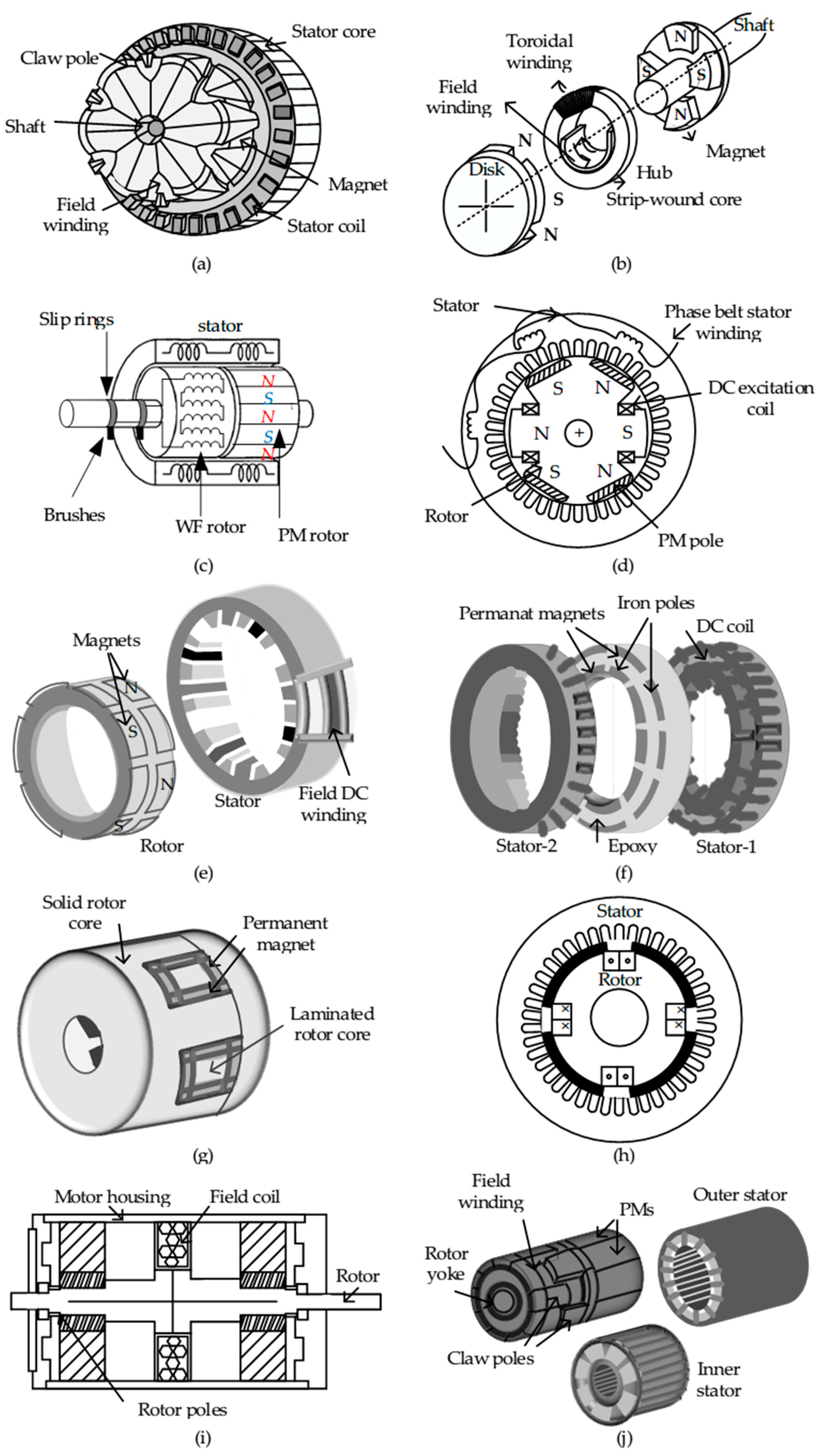
Rotating electric machines generally operate based on either magnetic or electrostatic fields. The machines that use the laws of electrostatics are not common [21,22], while most machines in today’s world operate based on magnetic field excitation. The need for energy conversion systems has driven the industry to explore innovative approaches to modify the excitation field for the benefit of power density, reliability, and controls, which are often defined by the application [23]. The modification of the excitation field may take place by adjusting a current into a field winding, such as in conventional synchronous machines, or by introducing additional fields, where such machines are sometimes referred to as ‘hybrid’ excited machines [24].

2.1. Topologies

Different types of hybrid excitation machines and their features have been studied. The authors in [25] have compared a few different types of structures for hybrid excited claw-pole machines such as the claw-pole DC excited synchronous machine (CPM), the inter-pole permanent magnet hybrid excited claw-pole machine (IPM-HECPM), and the hybrid excited brushless claw-pole machine (HEBDCPM) in terms of the machine’s flux path and torque production capability. The schematic of the machine is shown in Figure 1a, illustrating a combination of the magnetic fields from PMs and field winding. The claw-pole rotor consists of several magnetic poles, typically three or four, arranged in a claw-like shape as shown in Figure 1a. These poles are made of a soft magnetic material, such as laminated steel, and are mounted on a rotor shaft. PMs are embedded in the rotor, providing partial excitation for the machine, while the DC field winding can be placed on a stator or rotor depending on the type of claw-pole machine [25]. This is based on the size of the machine, such that for the large machines used in industrial and power plant applications, the DC field is stator-mounted, which allows for better heat dissipation and easier access for maintenance and control [26]. The isolation between the stator and field winding can be achieved by using insulating materials, such as varnish or insulating tape, between the windings. Additionally, the DC field winding and the main stator winding are connected to separate terminals or circuits to prevent unintended electrical connections [27]. For the smaller machines, including automotive alternators, the DC field winding is rotor-mounted, which can provide machine compactness and reduced weight, important factors in portable or vehicular applications [28,29]. When the field winding is on the stator, sliprings and brushes are not required [25,26,27,28]. In Figure 1a, the cylindrical wound field (WF) coil and the cylinder-shaped PM are placed around two overlapping plates holding claws. The field is mounted around the rotor core and fed through brush rings [26,27]. In [30], a toroidal stator transverse flux machine (TSTFM) is discussed, which is illustrated in Figure 1b. In a toroidal stator transverse flux machine, the stator is designed in a toroidal shape, resembling a donut or ring. The stator consists of laminated iron cores with windings wrapped around them [31]. Inside this stator, there are typically two sets of windings wound in opposite directions, while the rotor, located in the center of the toroid, comprises a series of iron or magnetic cores arranged in a circular pattern, facilitating a transverse flux path where the magnetic flux flows radially across the air gap between the stator and rotor [31,32]. This transverse flux configuration results in reduced core losses and improved power density compared to conventional radial flux machines [31]. In Figure 1b, the DC field is situated within the toroidal core, flanked by two rotating discs that alternate between PMs and soft magnetic poles. The windings are arranged concentrically or radially around the toroidal stator core, and the magnetic flux flows radially across the air gap between the stator and the rotor, rather than traveling along the axial direction, as in some other machine designs, hence the term “transverse flux” [32]. The authors in [33] present a hybrid excitation synchronous machine (HESM) with two-part rotor construction, PM excitation, and WF excitation, and the two rotor parts are separated by an air gap (Figure 1c). In this machine, the strength and direction of the rotor’s magnetic field can be controlled by adjusting the current in these field windings [34]. The flux generated by the field winding intentionally does not pass from the PMs due to the PMs’ high reluctance, resulting in a minimal magnetic force from the field winding [33]. Consequently, the magnetic flux within the machine’s air gap can be adjusted by changing the direction and strength of the field winding current [35]. The PM and WF excitation sources operate independently in parallel. A synchronous PM hybrid AC machine (SynPM) topology is presented in [36]. This machine includes a combination of four PM poles and two WF excitation poles on the same shaft, as well as brushes and slip rings (Figure 1d). In Figure 1d, the phase belt is formed by connecting three coils of the same phase in series [37]. The phase back-EMF has a different shape depending on whether the DC field excitation has positive, negative, or zero values. At all times, the circuit experiences the influence of one excitation pole and two PM poles, leading to a modifiable circuit back-EMF. The authors in [38,39] studied a consequent-pole PM hybrid excitation machine (CPPM), shown in Figure 1e, which inherently has similarities to TSTFM. In a traditional PM machine, all the magnet poles generally have the same polarity, meaning that adjacent poles have identical magnetic orientations, either north or south [39]. However, in the CPPM design, the poles are arranged in a consequent-pole configuration, as shown in Figure 1e. This means that as you move from one pole to the next along the rotor, the magnetic polarity alternates [40]. In other words, if the first pole is a north pole, the next adjacent pole will be a south pole, and this pattern continues throughout the rotor’s circumference. In CPPM topology, the field winding receives its excitation from a DC current [41]. In the absence of any field current, the machine’s excitation results solely from the rotor’s PMs and is primarily oriented radially [41]. Each PM interacts with a corresponding soft iron pole on the same half of the machine [42]. When energized with a positive current, the flux generated by the field winding aligns with and supplements the flux from the PMs. It completes its circuit within the same magnetic pole, thus within the air gap; the flux originating from the PMs and the field winding flows in opposite directions [40,41,42]. Consequently, the overall flux per pole diminishes as the field flux intensifies, traveling through the stator yoke in an axial manner [43]. Conversely, if the direction of the field current is reversed, the field flux changes its orientation, resulting in the total air gap flux being the cumulative sum of both components [43]. Consequently, as the field current strength increases, the flux per pole also increases [40,41,42,43]. The authors in [44,45] presented a field-controlled torus machine (FCTPM), shown in Figure 1f. This machine is an axial field version of CPPM. The axial flux surface-mounted PM machines come in two variants: one with n stators and n + 1 rotors, where n is greater than or equal to 1 , known as the torus type, and the other with n + 1 stators and n rotors, where n is greater than or equal to 1 , known as the AFIR type [46]. If you select n to be 1 for the external rotor and internal stator configuration, you can create the most basic torus machine structure [46]. Depending on whether the rotor is positioned on the outer or inner side of the stator, the machine’s characteristics and performance can vary. Outer-rotor machines may offer higher torque, while inner-rotor machines may be more compact. Figure 1f shows an example of a double-stator single rotor with two outer slotted stator discs. The rotor disc carries axially magnetized PMs alternatively placed with slotted magnetic iron pole pieces. Each slotted stator part consists of two cores, an inner and outer core, and there is a DC field winding between the stator’s inner and outer cores. Therefore, the machine has two stators with two sets of three-phase stator windings and two sets of DC field windings, as shown in Figure 1f. In [47], the imbricated hybrid excitation machine (IHEM) is presented, in which the rotor is composed of two magnetically isolated parts, including PM and field excitation, which are located on either the stator or the rotor. All three types of such machines, i.e., IHEMs, homopolar hybrid excitation synchronous machines (HHESMs), and bipolar hybrid excitation synchronous machines (BHESMs), combine PM excitation with field winding excitation, allowing for precise control of magnetic fields [47]. The IHEMs and HHESMs have the capability to switch between PM and field winding operation, providing versatility in different operating conditions [48]. The BHESMs, on the other hand, offer high torque density and dynamic response due to their rotor-mounted PMs. The choice between these machine types depends on the specific requirements of the application, such as efficiency, controllability, and torque density [48]. In applications demanding high performance, BHESMs may excel, while in scenarios where versatility is key, IHEMs and HHESMs are favored [49]. Figure 1g shows the rotor details for HHESMs. The authors in [50] discussed a series of double-excited synchronous machines (SDESMs). Unlike the other mentioned machines, in this case, the field excitation winding is fixed on the rotor and in a series magnetic configuration with surface PMs (Figure 1h). The authors in [51] proposed a switch reluctance machine (SRM) with a field assistance generator, in which two stator and two rotor sections are placed on both sides of the field coil assembly and the rotor has neither PM nor field excitation. In general, for all the double-excitation machines, at least two sources of magnetization are involved, see Figure 1i. In [52], a dual-stator hybrid excited synchronous generator (DSHESG) is presented. In this machine, the stator is composed of the outer stator, inner stator, and field winding, and the rotor consists of PMs, claw poles, a rotor yoke, and a cup rotor (Figure 1j). Typically, PM serves as the primary source of excitation, generating the main magnetic field [53,54]. Additionally, a WF component plays a role in adjusting the distribution of magnetic flux in the machine. It achieves this by either amplifying or diminishing the influence of the PM field, depending on the direction of the DC excitation current applied to the WF [55]. The PM field ensures a consistent flow of magnetic flux in the air gap. The WF source is excited by a DC source, and its purpose is to control or modify the distribution of magnetic flux in the air gap [56]. This can be achieved by either increasing or decreasing the strength of the field produced by the WF [57,58]. The authors in [59,60,61,62] propose a hybrid excitation topology similar to the HESM topology in [57], i.e., with a PM and WF rotor mounted axially on the same shaft but with a design that provides a trapezoidal EMF. This design is intended for generators in wind turbines, where the trapezoidal back-EMF results in lower rectified DC and subsequent reduced DC capacitive filtering, which in turn enhances the reliability of the conversion system as capacitors are a major reliability issue. A similar HESM topology for electric vehicle applications [63] and space power system applications, i.e., power generation on the Moon and Mars [64], has been proposed in the literature. Table 1 summarizes various hybrid machine topologies, highlighting their unique features and methods of excitation.

2.2. Application

The diverse range of hybrid machines, including CPMs, TSTFMs, HESMs, SynPMs, CPPMs, FCTPMs, HHESMs, SDESMs, SRMs, and DSHESGs, presents a spectrum of benefits and applications across industries. For instance, in aerospace and automotive applications, a CPM commonly operates at 480 V with 100 kW power and four poles [25,26,27,28,29], excelling in compact spaces with its enhanced torque density and efficiency. A TSTFM, widely utilized in the automotive and industrial sectors, typically operates at 690 V with 2 MW power and 12 poles [30,31,32], merging transverse flux and SRM technologies to meet high-power-density demands. A HESM finds its niche in marine and wind turbine applications, often operating at 6600 V with 5 MW power and eight poles [33,34], offering superior control flexibility and efficiency for variable speed requirements. SynPMs, commonly employed in automotive and wind turbine sectors, are characterized by 400 V with 500 kW power and six poles [36,37], catering to the needs of electric vehicle propulsion with their high efficiency and power density. CPPMs, utilized in rail traction, typically operate at 1500 V with 1.5 MW power and 10 poles [38,39], providing a balance between cost-effectiveness and performance. FCTPMs, frequently used in robotics and aerospace, operate at 400 V with 200 kW power and eight poles [44,45,46], offering precise flux control and high power density. HHESMs, commonly found in renewable energy systems and electric vehicle propulsion, operate at 6900 V with 10 MW power and 14 poles [47,48,49], facilitating controllability and efficiency. SDESMs, suitable for marine applications, typically operate at 33 kV with 20 MW power and 20 poles [50], providing high power density and efficiency. SRMs, commonly employed in industrial applications, operate at 690 V with 100 kW power and six poles [51], offering simplicity and ruggedness for reliability in harsh environments. Finally, DSHESG, utilized in wind power generation and grid stabilization, typically operates at 11 kV with 3 MW power and 10 poles [52,53,54,55,56,57,58], combining doubly salient topology and hybrid excitation to serve its purpose effectively. Each of these machines caters to specific requirements, offering a wide array of benefits tailored to diverse industrial needs. Table 2 summarizes these various hybrid machine types along with their applications and key parameters. Each of these machines caters to specific requirements, offering a wide array of benefits tailored to diverse industrial needs.

3. Multiphase Winding

The most common machines in terms of number of phases are the three-phase machines [65]. However, in recent years, there has been a growing interest in multiphase (greater than three-phase) machines due to their improved power density, torque density, efficiency, reliability, fault tolerance, and lower torque ripple, among other application-specific advantages [66,67,68,69]. The authors in [70] designed a PM machine with multiphase windings, aiming to enhance its fault tolerance capabilities. Under both normal and open-circuit conditions and using the instantaneous power approach, the paper demonstrates lower torque ripples and improved fault tolerance as a result of higher phase numbers. The authors in [71] conduct a comparison between five-phase and six-phase fault-tolerant outer rotor PM machines featuring fractional-slot concentrated windings (FSCWs). The study reveals that machines with a higher number of phases exhibit reduced active material mass due to shorter end windings. The authors in [72] examine a rewinding method, suggesting an equal division of turns between the star and pentagon coils for a five-phase machine. This paper investigates two options: constant current with reduced voltage and constant voltage with reduced current. The former option, utilizing only one DC-link capacitor instead of two, enhances system reliability. The authors in [73] address the position sensorless control of a seven-phase bi-harmonic surface-mounted PM machine. This machine, known for its tooth-concentrated winding and specific magnet segmentation, possesses a back-EMF where both the fundamental and third harmonics are of comparable magnitude. This unique characteristic enhances the machine’s potential to operate without a position sensor. The authors in [74,75] investigate the potential of controlling a five-phase induction machine through a three-phase inverter with the aid of a three-to-five-phase transformer. Two models of the system, based on per-phase modeling, are introduced: one representing the system as a three-phase induction machine, and the other as a five-phase induction machine. The dynamic behavior of the system is inferred from these models, resulting in an equivalent dynamic model of a three-phase or a five-phase machine. In a multiphase machine, the arrangement of the winding plays a crucial role in determining the machine’s performance and the resulting EMF characteristics [76]. There are two common winding arrangements in multiphase machines: concentrated winding and distributed winding [77]. In concentrated winding, all the coils of each phase are wound concentric to each tooth and then connected in series or parallel to form a phase [78]. This arrangement is commonly found in small- and medium-sized multiphase machines [79]. The concentrated winding arrangement can lead to a higher back-EMF per phase, as all the turns are concentrated in one location [80]. The concentrated arrangement provides better magnetic coupling between the stator and rotor, resulting in a higher winding factor. As a consequence, the generated back-EMF waveform is generally more pronounced, and the machine exhibits a smoother and more stable torque output [81]. In distributed winding, the turns of each phase are spread over several slots, creating a more spread-out winding pattern [82]. This arrangement is commonly found in large and high-power multiphase machines [83]. The distributed winding arrangement can lead to a more sinusoidal back-EMF waveform, especially when there are a higher number of slots per phase [84]. The distributed winding configuration results in a more symmetrical magnetic field distribution, reducing harmonic content in the back-EMF and overall output. By increasing the number of phases, the angle between phases will decrease by the rate of 1 / n [85]. The Symmetrical Winding (SW) configuration is fundamental in electric machines, distributing phases evenly around the stator [86]. The authors in [86] explain that Figure 2 shows the main ideas of SW configurations. In Figure 2, examples of SW configurations accommodating an odd number of phases are presented. For instance, Figure 2a shows a three-phase SW, where each phase is 120 degrees apart, and Figure 2b illustrates a nine-phase SW, with each phase separated by 40 degrees. These Figures vividly demonstrate how the phases are distributed around the stator, highlighting the equidistant arrangement of phases, which is crucial for balanced operation and efficient energy conversion. However, the simplicity of SW configurations encounters a limitation when dealing with an even number of phases. As depicted in Figure 2, when the number of phases is even, such as in Figure 2c (a six-phase SW) or Figure 2d (a 10-phase SW), the phasors of opposing magnetic axes overlap. This overlap results in redundancy, where one phase is essentially overlapped by its opposite, making the configuration less efficient. Despite this limitation, SW configurations remain a cornerstone in electrical engineering, particularly in applications requiring balanced three-phase power, where they play a crucial role in achieving optimal performance and energy efficiency [87,88]. The SW setup, effective for odd phases, struggles with even numbers. To address this, phases can be asymmetrically grouped to accommodate both even and odd phase counts. This method offers a more flexible winding solution, as demonstrated in Figure 2e,f, where configurations such as the six-phase YY30 and nine-phase YY20Y40 ASW are depicted. These examples show how asymmetric grouping allows for accommodating various phase counts while maintaining an approximate sinusoidal distribution.
Representing these windings in practical reference frames, such as the d-q frame or the 123 frame, provides a more versatile solution. The 123 frame, as discussed in the literature [87], condenses all magnetic phasors into half the circumference, ensuring an equal distribution of magnetic phasors.
Note: For the following features, it is assumed that the physical structure of the machine stays unchanged between three-phase and multiphase winding. Additionally, although these features are generally applicable across a variety of multiphase machines, specific gains and benefits are to be evaluated for the chosen number of phases, application, and machine topology, among other factors [88]. The study in [89] illustrates the winding arrangements for different rotor phases. To achieve 16 phases, either a series or parallel connection can be utilized. In the parallel connection, each coil represents a phase leg, while in the series connection, two diagonally placed coils are connected to form one phase. Employing a 16-phase parallel connection minimizes the interconnection wiring, which is advantageous for mass production [88]. For eight- and four-phase configurations, four and eight coils are connected in series to form one phase, respectively. This assumes 1.0 per unit (p.u.) turns per phase for the 16-phase parallel connection, with phase current and resistance both at 1.0 p.u. and keeping the ampere-turn per phase and total copper losses constant. The eight- and 16-phase systems yield a 4% higher peak voltage and consequently higher power density compared to the four-phase system. However, the 16-phase parallel winding results in the lowest phase current and rectified DC-link ripples. Therefore, the authors in [88] selected the 16-phase parallel option as the final design for the brushless exciter.
The authors in [89] present the characterization and operational envelope of a nine-phase hybrid permanent magnet (HPM) generator within a series hybrid electric vehicle (SHEV) powertrain. The WF rotor of the hybrid machine generator is powered by an external DC source through slip rings and brushes. The rotor lamination contains 32 slots, and the DC winding consists of 32 series coils wound around the rotor teeth. The phase belt, which determines the number of slots per pole per phase, is 3/8 for the three-phase and 1/8 for the nine-phase hybrid machine stator winding. This results in a concentric winding with 36 coils wound around the stator teeth. In a parallel study, the authors in [90] compare the three-phase winding with nine-phase winding for EVs and conclude that in the nine-phase winding, there is a 1.53% and 4.2% increase in the fundamental winding factor and back-EMF compared to three-phase windings. The authors in [91] discuss the winding layout for a bearingless motor designed with a multiphase combined winding approach. This motor is rated at 30 kRPM and 25.5 kW, with a diameter of 220 mm and an axial length of 100 mm. The Tm matrix entries are calculated using finite element analysis (FEA). The multiphase combined winding design allows for the transformation of conventional motors into bearingless motors by adjusting phase currents. This involves two current components: one for torque and another for suspension force. Using the Clarke transformation, force and torque can be independently controlled. This formal design procedure can be applied to any multiphase winding configuration and supports popular designs such as concentrated- and fractional-slot windings. The authors in [92] present an innovative single-layer winding arrangement for a high-power medium-voltage induction motor (IM). This IM is an asymmetrical nine-phase machine with a spatial phase shift of 20° between the three three-phase winding groups. The nine phases are connected to form six terminals, which are connected to three-phase inverters. The proposed nine-phase six-terminal (9P6T) winding configuration achieves a unity winding factor. In this configuration, the currents of the three three-phase winding sets differ in magnitude. The authors in [93] study an asymmetrical six-phase winding configuration for fractional-slot windings with an even number of phases. This configuration consists of two regularly alternating types of phase belts. Each type of phase belt belongs to a single phase, causing the six-phase winding to split into two symmetrical three-phase windings. Each of these symmetrical windings has a different number of slots per pole and phase, as well as a different winding factor. This example demonstrates how an asymmetrical m-phase winding with an even number of phases and an even denominator of slots per pole and phase can be divided into two symmetrical windings with m/2m/2 phases.

3.1. Advantages of Multiphase Winding

In general, some benefits of the multiphase winding include:
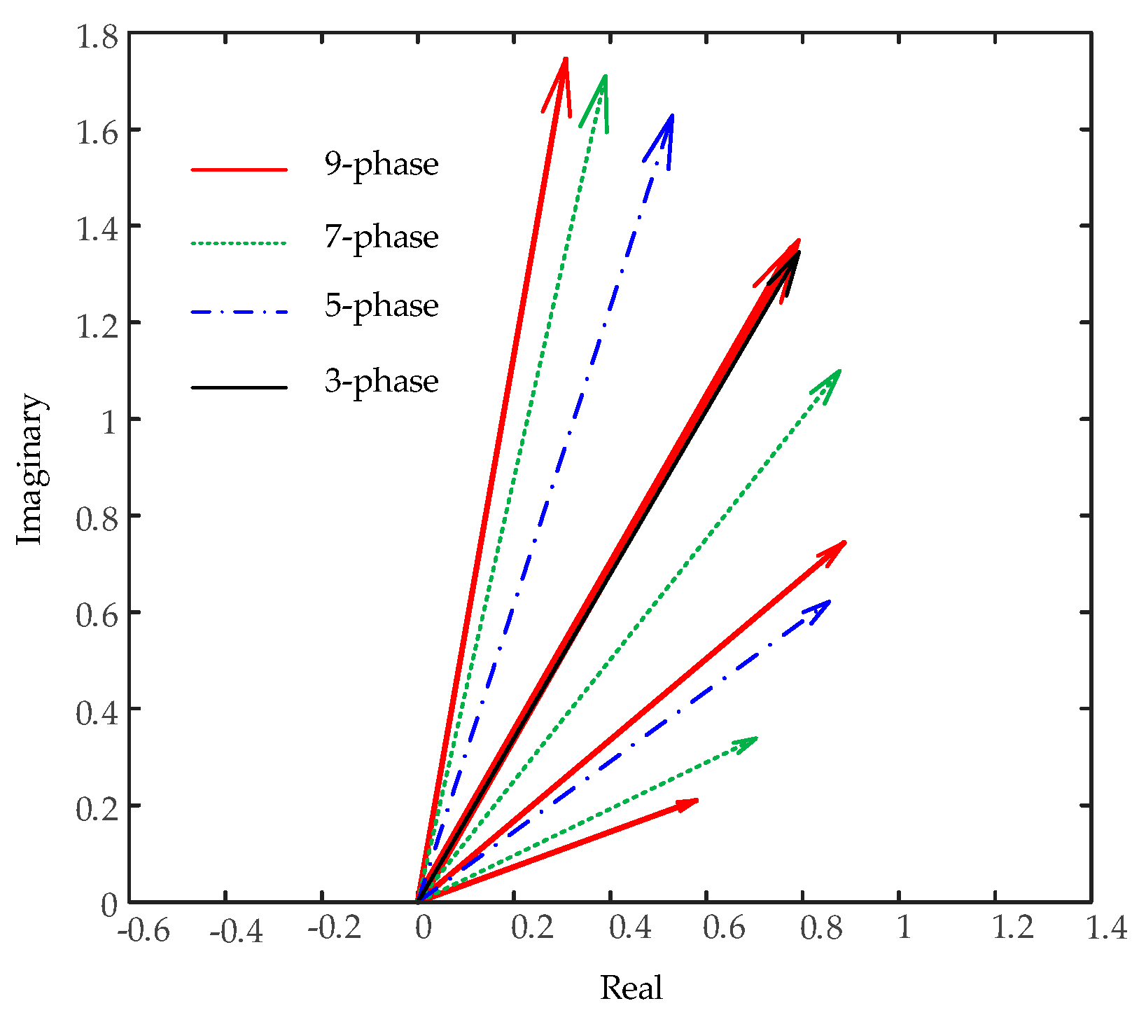
  • Increased Back-EMF: This generally results in greater power density and efficiency [80]. The primary reason for the larger back-EMF in multiphase machines is the concept of the “winding factor”. The winding factor is a measure of how effectively the winding contributes to the generation of the back-EMF in the machine. In a single-phase machine, the winding factor is limited because the winding is concentrated in one phase, resulting in less effective use of the available magnetic circuit [94]. In contrast, in a multiphase machine, the windings are distributed among multiple phases, resulting in a smaller angle between the induced voltage of each phase. The total phase back-EMF is the sum of a number of back-EMF vectors from the coils associated with a phase, hence the smaller angle results in a larger back-EMF amplitude [95,96]. As a consequence, each winding contributes more effectively to the overall generation of the magnetic field and, consequently, the back-EMF. This balanced and spatially distributed magnetic field results in a more stable and consistent back-EMF waveform, reducing harmonic content and improving the machine’s performance [97].
  • Improved Fault Tolerance: Multiphase systems exhibit better fault tolerance compared to three-phase and single-phase systems due to their inherent redundancy and distributed winding configurations [98]. In some cases, when a fault occurs in one phase, it may be possible to isolate and disconnect the faulty phase while allowing the machine to continue operating with the remaining healthy phases [99]. This selective isolation helps in preventing cascading failures and protects the overall system integrity. In contrast, the three-phase machines have a smaller number of phases and losing a phase will lead to a larger portion of the power being lost and/or overloading the remaining two phases. However, in multiphase winding, as there are a greater number of phases, the overload will be lighter and there is less chance of shutting down the machine.
  • Improved Power Density and Efficiency: Multiphase machines increase power density through a combination of design features and operational advantages [100]. By allowing for higher slot fill factors and reduced current ripple, multiphase configurations enable more efficient use of available space and increased current-carrying capability, translating to greater power density [101]. In addition, the multiphase winding improves the back-EMF. Therefore, for the same output power, the current will be smaller; this results in lower losses and greater power density and/or efficiency.
  • Improved Reliability: Multiphase machines offer enhanced thermal management capabilities, allowing for more effective heat dissipation and temperature regulation across the machine, which in turn reduces the risk of overheating and insulation degradation [102]. Moreover, the versatility of multiphase control strategies enables fault detection and isolation algorithms to be implemented more effectively, facilitating proactive maintenance and fault mitigation strategies [103], improving reliability.
  • Reduced Torque Ripple: Multiphase machines, especially those with a higher number of phases, have reduced torque ripple compared to three-phase machines [104]. This reduced torque ripple translates to smoother operation and less mechanical stress on the system, making it more resilient to faults and failures [105]. Multiphase machines utilize multiple phases with distributed windings, resulting in a smoother and more continuous rotating magnetic field [106]. The balanced distribution of winding coils around the stator helps reduce torque pulsations and harmonics, leading to a more constant torque output [104,105,106]. This smoother torque production results in improved mechanical performance and reduced mechanical stress on the machine. On the other hand, the distributed winding and increased number of phases allow for better utilization of the available magnetic materials, leading to higher torque generation without increasing the machine’s physical size significantly [107]. Another element can be the cogging torque, also known as detent torque, which is an undesirable torque variation that occurs due to the interaction between the stator and rotor teeth in electric machines. Multiphase machines with distributed windings generally exhibit reduced cogging torque [107]. The smooth and evenly distributed magnetic field helps minimize the cogging effect, leading to improved torque stability.
  • Lower Harmonic Distortion: In multiphase machines, the winding coils are distributed symmetrically around the stator, resulting in a more balanced and uniform magnetic field [108]. This balanced distribution helps to minimize the generation of harmonics during the operation of the machine [109]. The use of multiple phases allows for the cancellation of some harmonics that may be present in the individual phase currents [110]. As the phases are evenly spaced in the electrical cycle, the harmonic components of each phase tend to sum up in a way that some harmonics cancel each other out, reducing the overall harmonic content in the output [109,110].

3.2. Selection of Number of Phases

As discussed, the higher number of phases improves the winding factor, which leads to increased back-EMF/terminal voltage, as shown in Figure 3. In addition, for applications with an electric drive (inverter/active rectifier), once rectified, voltage from a multiphase winding will result in a higher average value compared to three-phase rectified voltage, as shown in Figure 3. In a multiphase system, as the number of phases increases, the electrical angle between phase voltages is reduced. Figure 4 shows the coil representation (in electrical degree) for three-phase, five-phase, seven-phase, and nine-phase winding. In a standard three-phase system, the voltage vectors are displaced by 120° from one another, while this reduces as the number of phases increases. In a nine-phase system, the angle between two consecutive phases is 40°. Hence, when rectified, the lower phase angle will result in less voltage ripple. As seen from Figure 3, the ripple in a three-phase system is 15%, while this is less than 2% in a nine-phase system (note: this is an example of multiphase winding for a HESM with specifications listed in [59]). The percentage ripple will depend on the winding arrangement. Reduced ripple, i.e., a reduction in perk-to-peak ripple, will contribute to increased average voltage. As explained by the authors of [57,58,59,60], it can be seen from Figure 3 that by assuming a 1.0 back-EMF for the three-phase system, the nine-phase back-EMF is increased by 4.2%; the average rectified DC voltage for a three-phase system is 1.6 p.u. while this is close to 2.0 p.u. for the nine-phase system. It is worth noting that in a three-phase system, the line-to-line voltages between the phases are the same; however, the line-to-line voltage for a multiphase system varies. For instance, for a five-phase system with an angular displacement of 2 π / 5 between adjacent coils (Figure 4b), there are two line-to-line voltages, namely the voltage between phases 1 and 2 ( V 12 ) and the voltage between phases 1 and 3 ( V 13 ), which can be calculated as follows:
V 1 i = A s i n ω t A s i n ω t 2 i 1 π m = B c o s ω t i 1 π m
B = A c o s i 1 π m
where i can have a value from 2 to m + 1 2 , m is the number of phases, A is the amplitude of the phase voltage, ω is the angular frequency, and t signifies time. Figure 5 shows the vector diagram of line-to-line voltages for different multiphase systems.
For a seven-phase system, with an angular displacement of 2 π / 7 between neighboring coils, there are three line-to-line voltages, V 12 , V 13 , and V 14 (Figure 4c), and B is calculated as shown in Table 3. Figure 4d illustrates a graphical depiction of a nine-phase winding with an angular displacement between adjacent coils of 2 π / 9 (40°). As shown, there exist four line-to-line voltages, denoted as V 12 ,   V 13 ,   V 14 , and V 15 . Hence, B is calculated as shown in Table 3.
It is worth noting that as the number of phases increases, the gains (i.e., increased back-EMF, increased average rectified DC voltage, and reduced ripple) become less. As seen in Figure 3, the increase in the rectified DC voltage saturates at 2.0 p.u., and for the phases beyond that, the gains are minimal while the winding complexity increases. Moreover, opting for an odd-phase setup results in a further decrease in rectified DC voltage ripple when contrasted with a consecutive even-phase configuration, as seen in Figure 3. Table 3 summarizes the above explanation for multiphase winding. Expanding the number of phases in electric machines brings about several advantages. Smaller phase shifts between phase voltages and currents are achieved, resulting in reduced ripple content at higher frequencies and an elevated average DC voltage post-rectification. This reduction in ripple content allows for the downsizing of installed DC capacitive filtering elements, leading to a decrease in converter failure rates and an improvement in reliability. Capacitors, in particular, exhibit a high failure rate in power electronics converters, contributing to 20% of failures according to Figure 6. Conversely, solid-state switches are responsible for 34% of converter failures [111]. Understanding these failure mechanisms is crucial for enhancing the design and reliability of converters in electric machines.

4. Motor and Generator Modes in Hybrid Machines

The analytical models of hybrid machines presented in Section 2 are generic and apply to hybrid machines operating as a motor or generator. There is a limited amount of literature discussing the operation modes (motor and generator mode) of hybrid machines, but this paper addresses these aspects comprehensively. There are distinct differences between the motor and generator operations of hybrid machines, as shown in the phasor diagram in Figure 7 [112,113]. The authors of [57,112] discuss that for generator operation, the back-EMF ( E p h ) results from the sum of the phase voltage ( V p h ) and the stator reactance ( j X s I p h ), as shown in Figure 7a. It is notable that for certain current angles, the back-EMF exceeds the maximum allowable value ( | E p h | m a x ). The effect of having a maximum WF current ( I f ) and a maximum back-EMF directly imposes a limitation on the minimum acceptable power factor of the generator when it operates at its rated kilovolt-amperes. The angle of the current ( I p h ) that necessitates the maximum attainable back-EMF while keeping V p h at its rated value determines the rated power factor of the generator. Although it is feasible to operate the generator at a lower (more lagging) power factor than the rated value, this can only be achieved by reducing the kilovolt-amperes supplied by the generator.
A hybrid machine in motor operation shares all characteristics with a generator, except for the reversal of power flow direction. Consequently, one can anticipate a reversal in the current flow direction within the stator of the hybrid machines. Hence, the equivalent circuit of a hybrid machine mirrors that of a generator, except for the reversal of the reference direction of the phase current. The resulting motor phasor diagram is depicted in Figure 7b. Due to the reversal of the phase’s current direction, there is a corresponding alteration in the Kirchhoff’s voltage law equation for the equivalent circuit. Formulating a Kirchhoff’s voltage law equation for the revised equivalent circuit yields:
V p h = E M F T o t a l + I p h R s + j I p h X s
For motor operation, the phase voltage ( V p h ) results from the sum of the back-EMF ( E p h ) and the stator reactance ( j X s I p h ). Neglecting the stator resistance, the hybrid machine’s apparent ( S p h ), active ( P p h ), and reactive ( Q p h ) power is calculated as:
S p h = V p h I p h = V p h   E P M δ + E P M δ V p h 0 j X s
P p h = V p h I p h cos φ = V p h   E P M sin δ + E W F sin δ X s
Q p h = V p h I p h sin φ = V p h E P M cos δ + E W F cos δ V p h 2 X s
When a load is attached to the shaft of a hybrid machine’s motor, the motor adjusts to develop sufficient torque to maintain synchronous speed. Initially, let us consider a hybrid machine operating with a leading power factor, as depicted in Figure 7b. If the load on the motor’s shaft increases, the rotor will initially decelerate. This deceleration causes the torque angle δ to enlarge, resulting in an increase in induced torque. Eventually, this augmented induced torque accelerates the rotor back to synchronous speed, albeit with a larger torque angle δ . Figure 7b portrays the motor’s phasor diagram before the load increment. The internal generated voltage E p h solely depends on the WF current and the machine’s speed, both of which remain constant initially. Thus, E p h must remain constant as the load varies. Although the distances are proportional to the power ( E p h s i n δ ) increase, the magnitude of E p h remains constant. As the load rises, E p h descends, as depicted in Figure 7b. With E p h descending further, the term j X s I p h must increase to span from the tip of E p h to V p h , hence causing an increase in the armature current I p h . It is noteworthy that the power-factor angle ( φ ) also undergoes changes, transitioning from leading to lagging as the load amplifies. Figure 7c shows a hybrid machine’s phasor diagram for a specific power, while illustrating the effect of WF current control. In this case, at each velocity, the output power, P p h , is maintained as a constant; therefore, the terms E p h sin δ and I p h c o s φ in Equation (5) must be maintained as a constant. This is denoted as fixed power in the phasor diagram in Figure 7c. As seen for each back-EMF, there is a PM portion and a WF portion of the vector. The PM portion stays constant as observed from Figure 7c, while the WF portion changes due to adjusting the WF current, I f . Since the power is maintained at a fixed value at each velocity, the term E p h sin δ should remain constant; therefore, the phasor E p h must ‘slide’ along the line of constant power, as shown in Figure 7c. In this diagram, as the I f increases, the E p h is moved from E p h 1 to E p h 2 , and then to E p h 3 , where the load angle from δ 1 opens up to δ 2 and then to δ 3 , respectively. Since V p h is constant, the angle and amplitude of the phase current ( I p h ) varies from a leading φ 1 to a lagging φ 2 , and then to φ 3 . However, term I p h cos φ must remain unchanged due to fixed active power. As a result, the amplitude of I p h sin φ , which is proportional to reactive power as seen from Equation (6), varies from Q 1 to Q 2 and then to Q 3 . Figure 7d shows the hybrid machine’s phasor diagram for fixed reactive power. In this case, reactive power, Q p h , is maintained as a constant; therefore, the term I p h s i n φ in Equation (6) must be maintained as a constant. This is depicted as a fixed reactive power in the phasor diagram in Figure 7d. As the power factor changes from φ 1 to φ 2 , the current amplitude increases from I p h 1 to I p h 2 ; therefore, the active power moves to P 2 . Q 2 has the same value as Q 1 but in a positive direction; therefore, the current is leading while active power has the same value as P 1 .
The power and torque behavior of hybrid machines vary based on the application. Table 4 lists analytical models of hybrid machines’ torque for some of the known applications, while hybrid machines’ torque and power characteristics are presented in Figure 8.
Figure 8a illustrates per unit power speed and torque speed characteristics for hybrid machines operating in fan-type (e.g., wind turbine) applications. The power is the cubic function of speed while the torque is in relation to the square of speed, as calculated in Table 4. The speed variation around the rated speed is approximately 10% (determined based on the application). In the high-speed operation region, i.e., above the rated speed, turbine torque decreases due to increased rotor speed while maintaining constant power. To maintain consistency with the low-speed operation, the rated turbine rotor speed is referenced as 1 p.u. When examining the torque speed characteristics of hybrid machines under various connection configurations, distinct behaviors emerge. When connected to an active converter, the hybrid machines’ torque speed pattern mimics that of a PM machine under inverter control, as shown in Figure 8b. This setup facilitates torque maximization during variable speed operation, with adjustments made during field weakening to facilitate speed increase. Common scenarios include hybrid machines operating as motors in electric vehicles (EVs) with inverters or as generators connected to active rectifiers in electric ships with variable speeds, albeit without field-weakening capabilities. On the other hand, connecting hybrid machines to a passive rectifier relinquishes torque control to machine parameters, resulting in less consistent torque levels.
The power and torque characteristics of hybrid machines operating as a synchronous machine connected to the grid are shown in Figure 8c, depicting various WF excitations. In this case, the torque developed is directly proportional to the applied voltage. Hence, hybrid machines connected to a grid are less sensitive to voltage variations. When a hybrid machine is connected to an infinite bus, its speed and terminal voltage remain fixed and unalterable. The sole control variables are the WF current and mechanical torque applied to the shaft. Figure 8c illustrates the relationship between power ( P ) and the power angle ( δ ). This curve, known as the power–angle characteristic curve, typically follows a sinusoidal pattern. For generators, power ( P ) is considered positive, while for motors, it is negative. The typical load angle is approximately 30 degrees electrical, and as the MW load increases, the load angle also rises, resulting in the generator delivering more power. The load angle can only be adjusted by modifying the input to the turbine. Mechanical power input is used to determine its power output. Governors regulate the output to accommodate variable loads. Speed control governors maintain the turbine speed at a constant by adjusting input (steam, gas, or water, depending on the type of prime mover or turbine) to the prime mover based on load feedback. System stability relies on maintaining the power angle ( δ ) within the range of −90° to +90°, where the slope of power with respect to angle ( d P / d δ ) is positive. Beyond this range, hybrid machines may lose synchronism, leading to instability. This instability can result in high fluctuations of current and voltage. Power transfer between sources becomes alternatively positive and negative, averaging to zero. When hybrid machines are linked to a three-phase grid, their behavior closely resembles that of a conventional synchronous generator, adhering to the grid’s characteristics.

5. Discussion and Recommendations

Table 5 presents a comprehensive cost analysis of multiphase and three-phase machines, highlighting key differences in manufacturing costs, maintenance costs, downtime costs, energy efficiency, lifecycle costs, and application suitability. Based on the discussion in [25,28,38,49,52], multiphase machines have higher manufacturing costs due to their complex windings and additional phases. However, they offer lower maintenance costs because of their improved fault tolerance, allowing them to continue operating even when some phases fail. This results in lower downtime costs compared to three-phase machines, which are more susceptible to complete shutdowns in case of failures.
Energy efficiency is another critical factor where multiphase machines excel, providing significant energy savings over time due to their higher efficiency rates. Consequently, their overall lifecycle costs are lower, taking into account maintenance, downtime, and energy savings. Multiphase machines are ideal for critical and high-duty applications, while three-phase machines are better suited for standard industrial applications.
Table 6 compares the performance metrics of multiphase, hybrid, and three-phase machines. Multiphase machines demonstrate superior power density and torque density, both of which are critical for high-performance applications [50]. They also have the highest efficiency at 95%, compared to 93% for hybrid machines and 90% for three-phase machines. In terms of reliability, multiphase and three-phase machines are rated highly, while hybrid machines are medium-rated [76,91]. Flexibility is another key factor, with hybrid machines being the most flexible due to their ability to adapt to varying operational requirements. However, this comes with the trade-off of higher complexity. Multiphase machines are rated medium for flexibility and high for complexity, whereas three-phase machines are low in both flexibility and complexity [22,37].
Based on the discussions earlier in this paper, the sizing of a hybrid electric machine depends on several factors, including the application, required speed, and torque. Specially sizing an electrical machine involves determining the appropriate dimensions and characteristics of its active components, such as windings, magnetic circuits, slots, and magnets, to meet specific performance requirements [114]. This process integrates both electromagnetic and thermal considerations to ensure optimal performance and efficiency.
The initial step in sizing an electrical machine is to define its specifications based on the intended application. Key parameters typically include the mechanical power output, the rotational speed at which the machine operates, and the operating voltage [115]. These specifications serve as the foundation for subsequent calculations and design decisions.
Electromagnetic loading is a crucial aspect of the sizing process, referring to the current density (electric loading) and magnetic flux density (magnetic loading) in the machine [58]. Magnetic loading, which is the air-gap flux density, is limited by the saturation level of the iron in the magnetic circuit, typically ranging from 0.3 to 0.8 T. Electric loading, which is influenced by the winding current and cooling capabilities, generally falls between 30 to 80 kA/m for forced air cooling systems [114,115,116].
With the electromagnetic loading parameters defined, the next step is to calculate the machine’s main dimensions, particularly the armature bore radius and the axial length. These dimensions are derived from the desired power output using the relationship between electromagnetic power, rotational speed, and the selected values for magnetic and electric loading. The authors in [115] explain that the transmitted electromagnetic power P t is given by:
P t = 2 π ω k w c o s φ B H π R 2 L
where P t is the transmitted power, is the rotational speed in rad/s, k w is the winding factor, c o s φ is the phase shift factor, B is the magnetic loading (air-gap flux density), H is the electric loading (tangential magnetic field), R is the armature bore radius, and L is the axial length.
By selecting initial values for B and H , and assuming reasonable values for k w and c o s φ , you can calculate the product R 2 L and subsequently determine suitable values for R and L .
Direct drive machines operate at lower frequencies, which results in higher torque requirements. According to the torque formula in Equation (8), this means that they require a larger diameter to achieve the necessary torque. In contrast, geared generators operate at higher rotor speeds, leading to lower torque requirements; therefore, they are designed with a longer axial length and a smaller diameter to accommodate the higher speed [58].
T = π D 2 2 l a Q B a v e
where D is the air gap diameter in mm, l a is the axial length in mm, Q is electric loading in A/mm, and B a v e is the air-gap average flux density (magnetic loading) in T.
The design of the machine’s windings is then addressed in [58,114,115], focusing on the selection of the number of slots, coils per phase, and turns per coil. The number of slots is determined by the machine’s pole pairs and desired slot-to-pole ratio, while the number of turns per coil is calculated to achieve the specified phase voltage. The electromotive force (emf) for each phase E can be expressed as:
E = 2 N k w ω R L B
where N is the number of turns per phase. This equation ensures that the machine can generate the required EMF while maintaining the correct operating voltage.
Conductor size and slot dimensions are determined based on the calculated current and chosen current density. The slot dimensions are designed to accommodate the required number of conductors with an appropriate fill factor, which accounts for the space taken up by insulation and conductors within the slot. As explained by authors in [114,115], the current I in the conductor is related to the electric loading H by:
H = N t I 2 π R
where N t is the total number of conductors of the armature winding.
Thermal considerations are a critical component of the machine sizing process. A lumped parameter thermal model is often employed to assess the temperature increase in different parts of the machine, ensuring that it operates within safe temperature limits [116]. The design must consider the chosen cooling method, such as forced air cooling, and ensure that the winding temperature remains within acceptable levels to avoid overheating and ensure long-term reliability [117,118].
The final stage in machine sizing involves optimization, where various design parameters are fine-tuned to minimize the machine’s weight, maximize efficiency, or meet other specific design objectives. This iterative process may involve the use of computational tools, such as spreadsheets or specialized software, to achieve an optimal balance of performance, size, and thermal management.

6. Conclusions

In conclusion, the exploration of multiphase and hybrid excited machines reveals significant advancements and potential in the field of electric machines. Multiphase machines offer notable benefits, including improved power density, efficiency, reliability, and fault tolerance compared to traditional three-phase systems. The hybrid excitation topologies, which combine PM and WF excitations, provide additional flexibility and performance optimization. This comprehensive review highlights the fundamental principles, advantages of multiphase windings, and the impact on DC link ripple. Applications across various industries, such as automotive, aerospace, marine, and renewable energy systems, demonstrate the versatility and relevance of these technologies. The study of motoric and generator modes in hybrid machines further underscores their adaptability and efficiency in diverse operational contexts. Additionally, this paper delves into detailed cost analysis and performance comparison of multiphase, hybrid, and three-phase machines. It emphasizes the importance of selecting and sizing electric machines based on specific application needs, considering factors such as electromagnetic and thermal constraints, power density, and lifecycle costs. As the demand for more efficient and reliable electric machines continues to grow, the developments in multiphase and hybrid topologies offer promising solutions to meet these evolving needs. Overall, understanding the complexities of multiphase and hybrid electric machines and addressing their reliability challenges are crucial steps in the pursuit of more efficient and sustainable electric machine technology. By doing so, we can continue to push the boundaries of innovation and meet the evolving needs of modern industry.

Author Contributions

Writing—original draft preparation, M.G.; writing—review and editing, O.B. and M.G.; conceptualization, O.B.; methodology, O.B. and M.G.; simulation, O.B. and M.G.; formal analysis and investigation, O.B. and M.G.; resources, M.G. and M.A.; data curation, O.B. and M.G.; supervision and project administration, O.B. All authors have read and agreed to the published version of the manuscript.

Funding

This research received no external funding.

Data Availability Statement

The data used during the study is available from the corresponding author upon reasonable request.

Conflicts of Interest

The authors declare no conflict of interest.

Abbreviations

V p h Phase voltageCPMClaw-pole machine
I p h Phase currentTSTFMToroidal stator transverse flux machine
R s Stator resistanceHESMHybrid excitation synchronous machine
R x Stator reactanceSynPMSynchronous permanent magnet machine
E M F t o t a l Total back-EMFCPPMConsequent-pole permanent magnet hybrid excitation machine
E M F P M Back-EMF from the permanent magnetFCTPMConsequent-pole permanent magnet hybrid excitation machine
E M F W F Back-EMF from the wound fieldHHESMHomopolar hybrid excitation synchronous machine
φ Power factor angleSDESMSeries double-excited synchronous machine
ω Angular frequencySRMSwitch reluctance machine
S p h Phase apparent powerDSHESGDual-stator hybrid excited synchronous generator
δ Torque angleSWSymmetrical winding
P p h Phase active powerASWAsymmetrical winding
Q p h Phase reactive powerSHEVSeries hybrid electric vehicle

References

  1. Mousavi, Y.; Bevan, G.; Kucukdemiral, I.B.; Fekih, A. Observer-Based High-Order Sliding Mode Control of DFIG-Based Wind Energy Conversion Systems Subjected to Sensor Faults. IEEE Trans. Ind. Appl. 2024, 60, 1750–1759. [Google Scholar] [CrossRef]
  2. Razi, S.; Mehreganian, N.; Soleiman Fallah, A. Chapter 3—Multiphysics of Wind Turbines in Extreme Loading Conditions. In Multiphysics: Advances and Applications; Academic Press: Cambridge, MA, USA, 2024; pp. 33–64. [Google Scholar]
  3. Notash, F.Y.; Rodriguez, J.; Tohidi, S. One Beat Delay Predictive Current Control of a Reduced-Switch 3-Level VSI-Fed IPMSM with Minimized Torque Ripple. In Proceedings of the 2021 IEEE International Conference on Predictive Control of Electrical Drives and Power Electronics (PRECEDE), Jinan, China, 18–20 September 2021; pp. 519–523. [Google Scholar]
  4. Manzoor, M.O.; Beik, O.; Ateeq, W.; Gholamian, M. Dynamic Modeling of Hybrid Generator-Based Wind Energy Conversion System. In Proceedings of the 2024 IEEE Power & Energy Society Innovative Smart Grid Technologies Conference (ISGT), Washington, DC, USA, 19–22 February 2024; pp. 1–5. [Google Scholar]
  5. Ateeq, W.; Beik, O.; Manzoor, O.; Gholamian, M. Control of Borrego Solar Microgrid Integrated with a Hybrid Generator-Based Wind Generation System. In Proceedings of the 2024 IEEE Power & Energy Society Innovative Smart Grid Technologies Conference (ISGT), Washington, DC, USA, 19–22 February 2024; pp. 1–5. [Google Scholar]
  6. Mohammadabadi, S.M.S.; Liu, Y.; Canafe, A.; Yang, L. Towards Distributed Learning of PMU Data: A Federated Learning based Event Classification Approach. In Proceedings of the 2023 IEEE Power & Energy Society General Meeting (PESGM), Orlando, FL, USA, 16–20 July 2023; pp. 1–5. [Google Scholar]
  7. Torkaman, H.; Shadaei, M.; Deyhimi, N.; Torkaman, H. Multi-objective Method to Reconfigure Radial Power Distribution System with DGs Considering Transformer Tap-Changing. In Proceedings of the 2021 IEEE International Conference on Environment and Electrical Engineering and 2021 IEEE Industrial and Commercial Power Systems Europe (EEEIC/I&CPS Europe), Bari, Italy, 7–10 September 2021; pp. 1–4. [Google Scholar]
  8. Bahrami, A.; Soltanifar, F.; Fallahi, P.; Meschi, S.S.; Sohani, A. Energy and Economic Advantages of Using Solar Stills for Renewable Energy-Based Multi-Generation of Power and Hydrogen for Residential Buildings. Buildings 2024, 14, 1041. [Google Scholar] [CrossRef]
  9. Xu, W.; Ying, F.; Yu, Y.; Yang, G.; Lee, C.H.T. Design and Analysis of a Five Phase Dual Stator Hybrid Excitation Machine with Spoke-type Permanent Magnet Rotor. In Proceedings of the 2023 26th International Conference on Electrical Machines and Systems (ICEMS), Zhuhai, China, 5–8 November 2023; pp. 1987–1992. [Google Scholar]
  10. Hou, J.; Geng, W.; Zhu, T.; Zhang, Y.; Li, Q.; Zhang, Z. A New Hybrid Excitation Machine with Dual-Stator Single-Rotor Axial-Flux Topology for Electric Vehicle Traction Application. In Proceedings of the 2021 24th International Conference on Electrical Machines and Systems (ICEMS), Gyeongju, Republic of Korea, 31 October–3 November 2021; pp. 1342–1347. [Google Scholar]
  11. Xia, C.; Feng, Y.; Jia, M.; Gao, Y.; Huang, S. A Novel Counter-rotating Axial-flux Hybrid-excitation Permanent Magnet Machine with Dual-rotor. In Proceedings of the 2023 IEEE International Magnetic Conference—Short Papers (INTERMAG Short Papers), Sendai, Japan, 15–19 May 2023; pp. 1–2. [Google Scholar]
  12. Khan, M.P.; Muhammad, F.; Shah, F.; Abduulah; Ahmad, A.; Rehman, N.U. Rotor Pole Based Dual Stator Hybrid Excitation of Flux Switching Motor. In Proceedings of the 2021 International Conference on Emerging Power Technologies (ICEPT), Topi, Pakistan, 10–11 April 2021; pp. 1–5. [Google Scholar]
  13. Ashofteh, H.; Behzadi Forough, A. Renewable Energy’s Potential Scrutiny by PVSYST and RETSCREEN Software: Case Study—Khoy City, Iran. Renew. Energy Res. Appl. 2022, 3, 207–216. [Google Scholar]
  14. Bizhanpour, A.; Hasanzadeh, N.; Najafi, A.F.; Magagnato, F. Investigation of Different Deflector Geometry and Mechanism Effect on the Performance of an In-Pipe Hydro Savonius Turbine. Appl. Energy 2023, 350, 121697. [Google Scholar] [CrossRef]
  15. Samavat, T.; Nazari, M.; Ghalehnoie, M.; Nasab, M.A.; Zand, M.; Sanjeevikumar, P.; Khan, B. A Comparative Analysis of the Mamdani and Sugeno Fuzzy Inference Systems for MPPT of an Islanded PV System. Int. J. Energy Res. 2023, 2023, 7676113. [Google Scholar] [CrossRef]
  16. Besati, S.; Mosallanejad, A.; Manjrekar, M. Control Strategy for Virtual Synchronous Generator Based on Y-Z Source Inverter in Islanded Grids. In Proceedings of the 11th International Conference on Electrical and Electronics Engineering (ICEEE), Marmaris, Turkey, 11 December 2023. [Google Scholar]
  17. Wu, Y.; Mustafeez-ul-Hassan; Luo, F. Design and Optimization of a Modular Multiphase Drive for Multiphase Machines. In Proceedings of the 2023 IEEE Applied Power Electronics Conference and Exposition (APEC), Orlando, FL, USA, 19–23 March 2023; pp. 1423–1428. [Google Scholar]
  18. Priyanka, C.P.; Nair, N.S.; Jagdanand, G. Thermal Analysis of Multiphase Induction Motor for Electric Vehicle Applications. In Proceedings of the 2022 IEEE Transportation Electrification Conference & Expo (ITEC), Anaheim, CA, USA, 15–17 June 2022; pp. 801–806. [Google Scholar]
  19. Shangguan, X.; Wu, X. Analysis of Rotor Slot Harmonics of Multiphase Induction Motor Based on Detection Coil. In Proceedings of the 2021 24th International Conference on Electrical Machines and Systems (ICEMS), Gyeongju, Republic of Korea, 31 October–3 November 2021; pp. 1386–1389. [Google Scholar]
  20. Liu, Y.; Xu, C.; Lin, Z.; Xiahou, K.; Wu, Q.H. Constructing an energy function for power systems with DFIGWT generation 872 based on a synchronous-generator-mimicking model. CSEE J. Power Energy Syst. 2022, 8, 64–75. [Google Scholar]
  21. Ludois, D.C.; Frankforter, K.J.; Ge, B.; Ghule, A.N.; Killeen, P.; Knippel, R.P. Macroscale Electrostatic Rotating Machines and Drives: A Review and Multiplicative Gain Performance Strategy. IEEE J. Emerg. Sel. Top. Power Electron. 2022, 10, 14–34. [Google Scholar] [CrossRef]
  22. Mayberry, M.; Ludois, D.C.; Severson, E.L. Toward Electrostatic Levitation of Macroscale Machines. IEEE Trans. Ind. Appl. 2022, 58, 4552–4561. [Google Scholar] [CrossRef]
  23. Levi, E. FOC: Field oriented control. In The Industrial Electronics Handbook: Power Electronics and Motor Drives; CRC Press: Boca Raton, FL, USA, 2011; pp. 24–32. [Google Scholar]
  24. Hlioui, S.; Gabsi, M.; Ahmed, H.B.; Barakat, G.; Amara, Y.; Chabour, F.; Paulides, J.J.H. Hybrid Excited Synchronous Machines. IEEE Trans. Magn. 2022, 58, 1–10. [Google Scholar] [CrossRef]
  25. Cao, Y.; Zhu, S.; Yu, J.; Liu, C. Optimization Design and Performance Evaluation of a Hybrid Excitation Claw Pole Machine. Processes 2022, 10, 541. [Google Scholar] [CrossRef]
  26. Boldea, I.; Tutelea, L.N.; Popa, A.A. Claw Pole Synchronous Motors/Generators (CP-SMs/Gs) Design and Control: Recent Progress. IEEE J. Emerg. Sel. Top. Power Electron. 2022, 10, 4556–4564. [Google Scholar] [CrossRef]
  27. Liu, C.; Wang, D.; Wang, S.; Niu, F.; Wang, Y.; Lei, G.; Zhu, J. Design and Analysis of a New Permanent Magnet Claw Pole Machine with S-Shape Winding. IEEE Trans. Magn. 2021, 57, 8103605. [Google Scholar] [CrossRef]
  28. Liu, C.; Yang, F.; Zhang, W.; Wang, Y. Design Optimization of a Novel Axial-Radial Flux Permanent Magnet Claw Pole Machine with SMC Cores and Ferrite Magnets. CES Trans. Electr. Mach. Syst. 2023, 7, 358–365. [Google Scholar] [CrossRef]
  29. Li, X.; Wang, X.; Dong, Y.; Lu, K.; Feng, X. Design and Analysis of Electric-Excitation Claw-Pole Field-Modulated Machine Considering Effective Harmonics. IEEE Trans. Ind. Appl. 2024, 60, 3893–3902. [Google Scholar] [CrossRef]
  30. Husain, T.; Hasan, I.; Sozer, Y.; Husain, I.; Muljadi, E. Design Considerations of a Transverse Flux Machine for Direct-Drive Wind Turbine Applications. IEEE Trans. Ind. Appl. 2018, 54, 3604–3615. [Google Scholar] [CrossRef]
  31. Ballestín-Bernad, V.; Artal-Sevil, J.S.; Domínguez-Navarro, J.A. Prototype of a Two-Phase Axial-Gap Transverse Flux Generator Based on Reused Components and 3D Printing. Energies 2023, 16, 1594. [Google Scholar] [CrossRef]
  32. Kaiser, B.; Parspour, N. Transverse Flux Machine—A Review. IEEE Access 2022, 10, 18395–18419. [Google Scholar] [CrossRef]
  33. Wu, S.; Wang, Y.; Tong, W. Design and Analysis of New Modular Stator Hybrid Excitation Synchronous Motor. CES Trans. Electr. Mach. Syst. 2022, 6, 188–194. [Google Scholar] [CrossRef]
  34. Amara, Y.; Ben Ahmed, H.; Gabsi, M. Hybrid Excited Synchronous Machines: Topologies, Design and Analysis; John Wiley & Sons: Hoboken, NJ, USA, 2023; Available online: https://onlinelibrary.wiley.com/doi/10.1002/9781394185931.fmatter (accessed on 18 February 2024).
  35. Chu, J.; Cheng, H.; Sun, J.; Peng, C.; Hu, Y. Multi-Objective Optimization Design of Hybrid Excitation Double Stator Permanent Magnet Synchronous Machine. IEEE Trans. Energy Convers. 2023, 38, 2364–2375. [Google Scholar] [CrossRef]
  36. Ren, J.; Wang, X.; Zhao, W.; Liu, F. Torsional Vibration Analysis and Optimization Design of the Surface PM Synchronous Machine with Reduced Torque Ripple. IEEE Trans. Transp. Electrif. 2023. early access. [Google Scholar] [CrossRef]
  37. Notash, F.Y.; Luckett, B.; He, J. A Simplified Fixed Switching Frequency Model Predictive Control for an AFPM Motor Drive in a Distributed Electric Aircraft Propulsion System. In Proceedings of the 2023 IEEE Energy Conversion Congress and Exposition (ECCE), Nashville, TN, USA, 29 October–2 November 2023; pp. 4690–4697. [Google Scholar]
  38. Wang, X.; Fan, Y.; Chen, J.; Lei, Y.; Chen, Q.; Lee, C.H.T. The Current Region Control Strategy with Wide Speed Range of Radial-Axial Consequent Pole Hybrid Excitation Machine for Electric Vehicles. IEEE Trans. Transp. Electrif. 2023, 10, 1377–1387. [Google Scholar] [CrossRef]
  39. Fan, Y.; Wang, X.; Chen, Q.; Lei, Y.; Lee, C.H.T. Comparison and Analysis of the Consequent Pole Double Stator Hybrid Excitation Machine for Wide Speed Range Driving Applications. IEEE Trans. Veh. Technol. 2023, 73, 120–130. [Google Scholar] [CrossRef]
  40. Zhu, J.; Yuan, X.; Xie, S.; Zhao, C.; Shen, F.; Chen, J.; Lee, C.H.T. Design and Analysis of a New Hybrid Excitation Vernier Motor with Reduced Permanent Magnet. IEEE Trans. Transp. Electrif. 2024. early access. [Google Scholar] [CrossRef]
  41. Yoon, K.-y.; You, Y.-m. Optimal Design of a Novel Consequent-Pole Interior Permanent Magnet Motor with Flared-Structured Rotor. Appl. Sci. 2024, 14, 1496. [Google Scholar] [CrossRef]
  42. Zhang, Z.; Zhang, M.; Yin, J.; Wu, J.; Yang, C. An Analytical Method for Calculating the Cogging Torque of a Consequent Pole Hybrid Excitation Synchronous Machine Based on Spatial 3D Field Simplification. Energies 2022, 15, 878. [Google Scholar] [CrossRef]
  43. Cao, G.; Ye, C.; Deng, C.; Wan, S.; Liu, K.; Yao, K.; Qi, X.; Lu, J.; Wang, Z. Theoretical Analysis for Rapid Design of Hybrid Excitation Synchronous Machine with Consequent Pole Rotor. IEEE Trans. Transp. Electrif. 2024. [Google Scholar] [CrossRef]
  44. Nishanth, F.; Van Verdeghem, J.; Severson, E.L. A Review of Axial Flux Permanent Magnet Machine Technology. IEEE Trans. Ind. Appl. 2023, 59, 3920–3933. [Google Scholar] [CrossRef]
  45. Marcolini, F.; De Donato, G.; Capponi, F.G.; Caricchi, F. Direct Oil Cooling of End-Windings in Torus-Type Axial-Flux Permanent-Magnet Machines. IEEE Trans. Ind. Appl. 2021, 57, 2378–2386. [Google Scholar] [CrossRef]
  46. Vidanalage, B.D.S.G.; Mukundan, S.; Li, W.; Kar, N.C. An Overview of PM Synchronous Machine Design Solutions for Enhanced Traction Performance. In Proceedings of the 2020 International Conference on Electrical Machines (ICEM), Gothenburg, Sweden, 23–26 August 2020; pp. 1697–1703. [Google Scholar]
  47. Zhang, W.; Yang, Z.; Zhai, L.; Wang, J. Speed Sensorless Control of Hybrid Excitation Axial Field Flux-Switching Permanent-Magnet Machine Based on Model Reference Adaptive System. IEEE Access 2020, 8, 22013–22024. [Google Scholar] [CrossRef]
  48. Agarala, A.; Bhat, S.S.; Zychma, D.; Sowa, P. A Novel Approach to Using Dual-Field Excited Synchronous Generators as Wind Power Generators. Energies 2024, 17, 456. [Google Scholar] [CrossRef]
  49. Asfirane, S.; Hliou, S.; Amara, Y.; Gabsi, M. Study of a Hybrid Excitation Synchronous Machine: Modeling and Experimental Validation. Math. Comput. Appl. 2019, 24, 34. [Google Scholar] [CrossRef]
  50. Wardach, M.; Palka, R.; Paplicki, P.; Prajzendanc, P.; Zarebski, T. Modern Hybrid Excited Electric Machines. Energies 2020, 13, 5910. [Google Scholar] [CrossRef]
  51. Xu, Z.; Li, T.; Zhang, F.; Zhang, Y.; Lee, D.-H.; Ahn, J.-W. A Review on Segmented Switched Reluctance Motors. Energies 2022, 15, 9212. [Google Scholar] [CrossRef]
  52. Zhao, J.; Wang, Y.; Li, J.; Hu, H. Comparative Study on Torque Performance of Five-phase Single-Stator and Double-Stator Permanent Magnet Synchronous Motors. CES Trans. Electr. Mach. Syst. 2022, 6, 46–52. [Google Scholar] [CrossRef]
  53. Liu, H.; Zhang, Y.; Zhang, F.; Jin, S.; Zhang, H.; Nian, H. Design and Performance Analysis of Dual-Stator Brushless Doubly-Fed Machine with Cage-Barrier Rotor. IEEE Trans. Energy Convers. 2019, 34, 1347–1357. [Google Scholar] [CrossRef]
  54. Chen, Y.; Zhuang, J.; Ding, Y.; Li, X. Optimal Design and Performance Analysis of Double Stator Multi-Excitation Flux-Switching Machine. IEEE Trans. Appl. Supercond. 2019, 29, 0601205. [Google Scholar] [CrossRef]
  55. Sun, C.; Li, J.; Ding, H.; Yang, H.; Han, S.; Han, N. Characteristic Analysis of a New Double Stator Bearingless Switched Reluctance Motor. IEEE Access 2021, 9, 38626–38635. [Google Scholar] [CrossRef]
  56. Liu, D.; Jin, J.; Sun, Y.; Tan, X.; Wang, B.; Feng, G.; Wei, L. Investigation of a Double-Stator Dual-PM Hybrid Excitation Machine with DC Bias Current. IEEE J. Emerg. Sel. Top. Power Electron. 2024, 12, 970–984. [Google Scholar] [CrossRef]
  57. Al-Adsani, A.S. Hybrid Permanent Magnet Machines For Electric Vehicles. Ph.D. Dissertation, University of Manchester, Manchester, UK, 2011. [Google Scholar]
  58. Al-Adsani, A.S.; Beik, O. Hybrid Electric Machine Concept. In Multiphase Hybrid Electric Machines; Springer: Cham, Switzerland, 2022; pp. 17–44. [Google Scholar]
  59. Yang, Q.; Zhao, C.; Zhang, W. Theoretical and Experimental Analysis of Electromagnetic Force Waves for Rotor Magnetic Shunt Hybrid Excitation Synchronous Motor. IEEE Sens. J. 2024, 24, 22511–22522. [Google Scholar] [CrossRef]
  60. Yang, Q.; Zhang, W.; Zhao, C. Research on Torque Performance of Marine Hybrid Excitation Synchronous Motors Based on PSO Optimization of Magnetic Permeability Structure. J. Mar. Sci. Eng. 2024, 12, 1064. [Google Scholar] [CrossRef]
  61. Guo, J.; Chen, Y.; Wu, W.; Wang, X.; Xie, Z.; Xie, L.; Shuai, Z. Wideband dq-Frame Impedance Modeling of Load-Side Virtual Synchronous Machine and Its Stability Analysis in Comparison with Conventional PWM Rectifier in Weak Grid. IEEE J. Emerg. Sel. Top. Power Electron. 2021, 9, 2440–2451. [Google Scholar] [CrossRef]
  62. Mseddi, A.; Dhouib, B.; Zdiri, M.A.; Alaas, Z.; Naifar, O.; Guesmi, T.; Alshammari, B.M.; Alqunun, K. Exploring the Potential of Hybrid Excitation Synchronous Generators in Wind Energy: A Comprehensive Analysis and Overview. Processes 2024, 12, 1186. [Google Scholar] [CrossRef]
  63. Al-Adsani, A.S.; Jarushi, A.M.; Beik, O. ICE/HPM generator range extender for a series hybrid EV powertrain. IET Electr. Syst. Transp. 2020, 10, 96–104. [Google Scholar] [CrossRef]
  64. Saude, B.; LaSart, N.; Blair, J.; Beik, O. Microgrid-Based Wind and Solar Power Generation on Moon and Mars. IEEE Trans. Smart Grid 2023, 14, 1329–1332. [Google Scholar] [CrossRef]
  65. Frikha, M.A.; Croonen, J.; Deepak, K.; Benômar, Y.; El Baghdadi, M.; Hegazy, O. Multiphase Motors and Drive Systems for Electric Vehicle Powertrains: State of the Art Analysis and Future Trends. Energies 2023, 16, 768. [Google Scholar] [CrossRef]
  66. Kindl, V.; Cermak, R.; Ferkova, Z.; Skala, B. Review of Time and Space Harmonics in Multi-Phase Induction Machine. Energies 2020, 13, 496. [Google Scholar] [CrossRef]
  67. Liu, Z.; Li, Y.; Zheng, Z. A review of drive techniques for multiphase machines. CES Trans. Electr. Mach. Syst. 2018, 2, 243–251. [Google Scholar] [CrossRef]
  68. Levi, E. Multiphase AC machines. In The Industrial Electronics Handbook: Power Electronics and Motor Drives; CRC Press: Boca Raton, FL, USA, 2011; pp. 3–31. [Google Scholar]
  69. Adil, W.A.; Mayer, J.S.; Greifelt, A.; Gerling, D. Novel Inherently Fault Tolerant Permanent Magnet Synchronous Machine (PMSM) with Multiphase Windings. In Proceedings of the 2021 24th International Conference on Electrical Machines and Systems (ICEMS), Gyeongju, Republic of Korea, 31 October–3 November 2021. [Google Scholar]
  70. Adil, W.A.; Mayer, J.S.; Greifelt, A.; Gerling, D. A new intelligent stator reconfigurable ampere response (ISRAR) method for open phase fault tolerant operation of multiphase machines. In Proceedings of the 2021 24th International Conference on Electrical Machines and Systems (ICEMS), Gyeongju, Republic of Korea, 31 October–3 November 2021. [Google Scholar]
  71. Yepes, A.G.; Lopez, O.; Gonzalez-Prieto, I.; Duran, M.J.; Doval-Gandoy, J. A Comprehensive Survey on Fault Tolerance in Multiphase AC Drives, Part 1: General Overview Considering Multiple Fault Types. Machines 2022, 10, 208. [Google Scholar] [CrossRef]
  72. Sizonenko, V.; Vitek, O. Preliminary Design and Comparison of 5 Phase and 6 Phase Fault Tolerant Outer Rotor Permanent Magnet Synchronous Machines with Different Electrical Steel. In Proceedings of the 2022 IEEE 20th International Power Electronics and Motion Control Conference (PEMC), Brasov, Romania, 25–29 September 2022. [Google Scholar]
  73. Tawfiq, K.B.; Ibrahim, M.N.; Sergeant, P. Analysis of Different Rewinding Configurations of Five-phase Synchronous Reluctance Machines. In Proceedings of the 2022 International Conference on Electrical Machines (ICEM), Valencia, Spain, 5–8 September 2022. [Google Scholar]
  74. Becker, F.; Scuiller, F. Sensorless controls of a 7-phase bi-harmonic Surface-mounted PM Machine. In Proceedings of the 2022 International Conference on Electrical Machines (ICEM), Valencia, Spain, 5–8 September 2022. [Google Scholar]
  75. Khelafi, A.; Djebli, A.; Ouadah, M.; Touhami, O.; Ibtiouen, R. Control of Five-Phase Induction Machine with Three-Phase Inverter via Three-to-Five Phase Transformer. In Proceedings of the 2020 International Conference on Electrical Machines (ICEM), Gothenburg, Sweden, 23–26 August 2020. [Google Scholar]
  76. Khelafi, A.; Djebli, A.; Ouadah, M.; Touhami, O.; Ibtiouen, R. Behavior Investigation of Five-Phase Induction Machine Fed by Sine Voltage Using Three-to-Five Phase Transformer. In Proceedings of the 2020 International Conference on Electrical Machines (ICEM), Gothenburg, Sweden, 23–26 August 2020. [Google Scholar]
  77. Ciriani, C.; Khan, H.A.; Mansour, K.; Olivo, M.; Tessarolo, A. A General Approach to the Design of Multi-Layer Fractional-Slot Concentrated Windings with Arbitrary Number of Slots, Poles and Phases. IEEE Access 2024. [Google Scholar] [CrossRef]
  78. Campagna, N.; Caruso, M.; Tommaso, A.O.D.; Miceli, R. A Comprehensive Generalized Theory and Classification of Multiphase Systems for Rotating and Linear Electric Machines. IEEE Trans. Energy Convers. 2024. early access. [Google Scholar] [CrossRef]
  79. Wang, W.; Wu, L. MMF Harmonic Analysis of Multi-M-Phase Fractional-Slot PM Machines with Partial Operating Winding Sets. IEEE Trans. Magn. 2024. [Google Scholar] [CrossRef]
  80. Cui, S.; Zhao, T.; Du, B.; Cheng, Y. Multiphase PMSM with Asymmetric Windings for Electric Drive. Energies 2020, 13, 3765. [Google Scholar] [CrossRef]
  81. Salem, A.; Narimani, M. A Review on Multiphase Drives for Automotive Traction Applications. IEEE Trans. Transp. Electrif. 2019, 5, 1329–1348. [Google Scholar] [CrossRef]
  82. Khamitov, A.; Severson, E.L. Design of Multi-Phase Combined Windings for Bearingless Machines. IEEE Trans. Ind. Appl. 2023, 59, 3243–3255. [Google Scholar] [CrossRef]
  83. Metwly, M.Y.; Abdel-Khalik, A.S.; Hamad, M.S.; Ahmed, S.; Elmalhy, N.A. Multiphase Stator Winding: New Perspectives, Advanced Topologies, and Futuristic Applications. IEEE Access 2022, 10, 103241–103263. [Google Scholar] [CrossRef]
  84. Martins, F.S.; Alvarenga, B.P.; Paula, G.T. Electrical Machine Winding Performance Optimization by Multi-Objective Particle Swarm Algorithm. Energies 2024, 17, 2286. [Google Scholar] [CrossRef]
  85. Chahba, S.; Krebs, G.; Morel, C.; Sehab, R.; Akrad, A. Design Optimisation Approach of an Outer Rotor Multiphase PM Actuator for Multirotor Aerial Vehicle Applications. Aerospace 2024, 11, 150. [Google Scholar] [CrossRef]
  86. Nishanth, F.; Khamitov, A.; Severson, E.L. Design of Multiphase Motor Windings for Control of Multiple Airgap Fields. In Proceedings of the 2022 IEEE Energy Conversion Congress and Exposition (ECCE), Detroit, MI, USA, 9–13 October 2022; pp. 1–8. [Google Scholar]
  87. Laksar, J.; Cermak, R.; Hruska, K. Challenges in the Electromagnetic Design of Multiphase Machines: Winding and Equivalent Circuit Parameters. Energies 2021, 14, 7335. [Google Scholar] [CrossRef]
  88. Fleitas, A.; Ayala, M.; González, O.; Delorme, L.; Romero, C.; Rodas, J.; Gregor, R. Winding Design and Efficiency Analysis of a Nine-Phase Induction Machine from a Three-Phase Induction Machine. Machines 2022, 10, 1124. [Google Scholar] [CrossRef]
  89. Al-Adsani, A.S.; Beik, O. Characterization of a Hybrid PM Generator Using a 32-Phase Brushless Excitation Scheme. IEEE Trans. Energy Convers. 2019, 34, 1391–1400. [Google Scholar] [CrossRef]
  90. Al-Adsani, S.; Beik, O. Design of a Multiphase Hybrid Permanent Magnet Generator for Series Hybrid EV. IEEE Trans. Energy Convers. 2018, 33, 1499–1507. [Google Scholar] [CrossRef]
  91. Khamitov, A.; Severson, E.L. Analysis and Design of Multi-Phase Combined Windings for Bearingless Machines. In Proceedings of the 2021 IEEE Energy Conversion Congress and Exposition (ECCE), Vancouver, BC, Canada, 10–14 October 2021; pp. 3949–3956. [Google Scholar]
  92. Chen, Q.; Li, G.; Cao, W.; Qian, Z.; Wang, Q. Winding MMF and PM MMF Analysis of Axial-Flux Machine with Multi-Phase and Multi-Layer Winding. Energies 2021, 14, 5147. [Google Scholar] [CrossRef]
  93. Slunjski, M.; Dordevic, O.; Jones, M.; Levi, E. Symmetrical/Asymmetrical Winding Reconfiguration in Multiphase Machines. IEEE Access 2020, 8, 12835–12844. [Google Scholar] [CrossRef]
  94. Arshad, M.; Beik, O.; Manzoor, M.O.; Gholamian, M. Stability Analysis via Impedance Modelling of a Real-World Wind Generation System with AC Collector and LCC-Based HVDC Transmission Grid. Electronics 2024, 13, 1917. [Google Scholar] [CrossRef]
  95. Karni, A.; Beik, O.; Homaeinezhad, M. A Modified Middle Point Clamped (MMPC) DC-DC Converter for All-DC Wind Generation Systems. In Proceedings of the 2024 IEEE Applied Power Electronics Conference and Exposition (APEC), Long Beach, CA, USA, 25–29 February 2024; pp. 325–332. [Google Scholar]
  96. Zhao, T.; Wu, S.; Cui, S. Multiphase PMSM with Asymmetric Windings for More Electric Aircraft. IEEE Trans. Transp. Electrif. 2020, 6, 1592–1602. [Google Scholar] [CrossRef]
  97. Huang, H.; Ma, F.; Fu, L.; Zhu, W.; Li, C. An Overview of Grounding Design and Grounding Fault Detection and Location Methods for a Multiphase Rectifier Generator Power Supply System. Machines 2023, 11, 985. [Google Scholar] [CrossRef]
  98. Akay, A.; Lefley, P. Research on torque ripple under healthy and open-circuit fault-tolerant conditions in a PM multiphase machine. CES Trans. Electr. Mach. Syst. 2020, 4, 349–359. [Google Scholar] [CrossRef]
  99. Gaetano, D.D.; Harikumaran, J.; Sala, G.; Degano, M.; Buticchi, G.; Gerada, C. On Torque Improvement by Current Harmonic Injection in Isotropic and Anisotropic Multiphase Machines. IEEE J. Emerg. Sel. Top. Ind. Electron. 2022, 3, 845–853. [Google Scholar] [CrossRef]
  100. Wang, P.; Gong, S.; Sun, X.; Liu, Z.; Jiang, D.; Qu, R. Fault-Tolerant Reconfiguration Topology and Control Strategy for Symmetric Open-Winding Multiphase Machines. IEEE Trans. Ind. Electron. 2022, 69, 8656–8666. [Google Scholar] [CrossRef]
  101. Homaeinezhad, M.; Beik, O. Development of a Generalized Multilevel SVM and Capacitor Voltage Balancing Strategy for Multiphase Three-Level NPC Converters. IEEE Open J. Power Electron. 2024, 5, 1059–1070. [Google Scholar] [CrossRef]
  102. Sala, G.; Mengoni, M.; Rizzoli, G.; Degano, M.; Zarri, L.; Tani, A. Impact of Star Connection Layouts on the Control of Multiphase Induction Motor Drives Under Open-Phase Fault. IEEE Trans. Power Electron. 2021, 36, 3717–3726. [Google Scholar] [CrossRef]
  103. Karni, A.; Beik, O.; Gholamian, M.; Homaeinezhad, M.; Manzoor, M.O. Multilevel Middle Point Clamped (MMPC) Converter for DC Wind Power Applications. Sustainability 2024, 16, 7563. [Google Scholar] [CrossRef]
  104. Olson, G.F.; Wu, Y.; Peretti, L. Parameter Estimation of Multiphase Machines Applicable to Variable Phase-Pole Machines. IEEE Trans. Energy Convers. 2023, 38, 2822–2831. [Google Scholar] [CrossRef]
  105. Sykes, R.L.; Summers, T.J.; Betz, R.E.; Torresan, H. Fault-Mitigation in Multi-Phase BLDC Machines—Literature Review. In Proceedings of the 2020 Australasian Universities Power Engineering Conference (AUPEC), Hobart, Australia, 29 November–2 December 2020; pp. 1–6. [Google Scholar]
  106. Tawfiq, K.B.; Abdel-Khalik, A.S.; Ibrahim, M.N.; EL-Refaie, A.M.; Sergeant, P. A Rewound Five-Phase Synchronous Reluctance Machine: Operating Voltage, Inductance Analysis and Comparison with Conventional Multiphase Machines. IEEE Trans. Ind. Appl. 2024, 60, 12–27. [Google Scholar] [CrossRef]
  107. Abu-Seif, M.A.; Ahmed, M.; Metwly, M.Y.; Abdel-Khalik, A.S.; Hamad, M.S.; Shehab. Data-Driven-Based Vector Space Decomposition Modeling of Multiphase Induction Machines. IEEE Trans. Energy Convers. 2023, 38, 2061–2074. [Google Scholar] [CrossRef]
  108. Beik, O.; Al-Adsani, A.S. A Wind Turbine Generator Design and Optimization for DC Collector Grids. IEEE J. Emerg. Sel. Top. Power Electron. 2022, 10, 484–493. [Google Scholar] [CrossRef]
  109. Sarfi, G.; Beik, O. MW-Scale High-Voltage Direct-Current Power Conversion for Large-Spacecraft Electric Propulsion. Electronics 2024, 13, 1455. [Google Scholar] [CrossRef]
  110. Talebzadeh, S.; Beik, O. Spacecraft Medium Voltage Direct-Current (MVDC) Power and Propulsion System. Electronics 2024, 13, 1810. [Google Scholar] [CrossRef]
  111. Homaeinezhad, M.; Beik, O. Modified Space Vector Modulation and Voltage Balancing of Multiphase Neutral Point Clamped Rectifier. In Proceedings of the 2023 IEEE Energy Conversion Congress and Exposition (ECCE), Nashville, TN, USA, 29 October–2 November 2023; pp. 3422–3428. [Google Scholar]
  112. Chapman, S. Electric Machinery Fundamentals, 5th ed.; McGraw-Hill Education: New York, NY, USA, 2011. [Google Scholar]
  113. Gholamian, M.; Beik, O. Reactive Power Control in All-DC Wind Generation System. In Proceedings of the 2023 IEEE Energy Conversion Congress and Exposition (ECCE), Nashville, TN, USA, 29 October–2 November 2023; pp. 579–583. [Google Scholar]
  114. Touhami, S. Analytical Sizing Models to Assess the Performances of High Specific Power Electric Motors for Hybrid Aircraft. Ph.D. Thesis, Institut National Polytechnique de Toulouse—INPT, Toulouse, France, 2020. Available online: https://theses.hal.science/tel-04170761/ (accessed on 1 July 2024).
  115. Mezani, S.; Belguerras, W.; Takorabet, N.; Lubin, T. Sizing Electrical Machines Using OpenOffice Calc. In Proceedings of the 9th European Conference for Aeronautics and Space Sciences (EUCASS), Lille, France, 3–8 July 2022. [Google Scholar]
  116. Rivera, C.A.; Poza, J.; Ugalde, G.; Almandoz, G. Industrial Design of Electric Machines Supported with Knowledge-Based Engineering Systems. Appl. Sci. 2021, 11, 294. [Google Scholar] [CrossRef]
  117. Fatemi, A.; Damodaran, S.; Ravi, G.; Shearer, C.; Pan, Y. Design Optimization of an Electric Machine for a 48-V Hybrid Vehicle with Comparison of Rotor Technologies and Pole-Slot Combinations. IEEE Trans. Ind. Appl. 2020, 56, 4609–4622. [Google Scholar] [CrossRef]
  118. Dong, C.; Qian, Y.; Zhang, Y.; Zhuge, W. A Review of Thermal Designs for Improving Power Density in Electrical Machines. IEEE Trans. Transp. Electrif. 2020, 6, 1386–1400. [Google Scholar] [CrossRef]
Figure 1. Hybrid machines’ schematics: (a) CPM; (b) TSTFM; (c) HESM; (d) SynPM; (e) CPPM; (f) FCTPM; (g) HHESM; (h) SDESM; (i) switch reluctance machine; (j) DSHESG [57].
Electronics 13 03636 g001
Figure 2. Symmetrical phasor of stator configuration accommodating odd and even number phases: (a) 3-phase, (b) 9-phase, (c) 6-phase, (d) 10-phase, (e) phasors representing 6-phase ASW, and (f) phasors representing 9-phase 20 40 ASW [87].
Electronics 13 03636 g002
Figure 3. Comparison of Multiphase back-EMF and rectified voltage [58].
Electronics 13 03636 g003
Figure 4. Multiphase coil representation. (a) 3-phase. (b) 5-phase. (c) 7-phase. (d) 9-phase.
Electronics 13 03636 g004
Figure 5. Vector diagram of line-to-line voltages for 3-ph, 5-ph, 7-ph, and 9-ph.
Electronics 13 03636 g005
Figure 6. Power Electronics Reliability in Electric Machines [111].
Electronics 13 03636 g006
Figure 7. Phasor diagram. (a) Generator phasor diagram. (b) Motor phasor diagram. (c) Constant power operation. (d) Constant reactive power operation [112,113].
Electronics 13 03636 g007
Figure 8. Hybrid machines’ torque and power characteristics. (a) Fan-type applications’ power speed and torque speed [59]. (b) PM machine power speed and torque speed. (c) Synchronous machine power-delta and torque speed.
Electronics 13 03636 g008
Table 1. Summary of Hybrid Machine Topology.
Hybrid Machine TypeSummary of Topology
CPMClaw-Pole Machine (CM): The claw-pole machine utilizes a combination of permanent magnets (PMs) and a DC field winding for excitation, providing flexibility in field control and torque production.
TSTFMToroidal Stator Transverse Flux Machine (TSTFM): This machine features a toroidal stator design with windings wrapped around laminated iron cores, providing a transverse flux path for reduced core losses and improved power density.
HESMHybrid Excitation Synchronous Machine (HESM): HESM employs both PM excitation and wound field (WF) excitation, allowing for precise control of magnetic field strength and direction.
SynPMSynchronous PM Hybrid AC Machine (SynPM): SynPM combines PM poles with WF excitation poles, providing a modifiable circuit back-EMF for enhanced control and performance.
CPPMConsequent-Pole PM Hybrid Excitation Machine (CPPM): CPPM features alternating magnetic polarities in its rotor design, providing flexible control of magnetic flux distribution through the interaction of PMs and the DC field winding.
FCTPMField-Controlled Torus Machine (FCTPM): FCTPM is an axial field version of CPPM, featuring outer slotted stator discs and axially magnetized PMs for improved torque and compactness.
HHESMImbricated Hybrid Excitation Machine (IHEM): IHEM combines PM and field excitation for precise control of magnetic fields, offering versatility in different operating conditions. Homopolar Hybrid Excitation Synchronous Machine (HHESM): HHESM allows for switching between PM and field winding operation, providing flexibility and efficiency in various applications.
Bipolar Hybrid Excitation Synchronous Machine (BHESM): BHESM offers high torque density and dynamic response due to its rotor-mounted PMs, making it suitable for demanding performance requirements.
SDESMSeries Double-Excited Synchronous Machine (SDESM): SDESM features a fixed field excitation winding on the rotor, providing control over magnetic fields and torque production.
Switch reluctance machineSwitch Reluctance Machine (SRM) with Field Assistance Generator: This machine utilizes field assistance to control the magnetic flux distribution, enhancing efficiency and performance.
DSHESGDual-Stator Hybrid Excited Synchronous Generator (DSHESG): DSHESG features PMs and a field winding on the rotor, providing control over magnetic flux distribution for improved efficiency.
Table 2. Summary of Hybrid Machine Applications and Parameters.
Hybrid Machine TypeApplicationVoltage LevelPower LevelNumber of PolesSpeed
CPMAerospace, Automotive480100 kW41500
TSTFMAutomotive and industrial applications6902 MW12600
HESMMarine, Wind turbine66005 MW81200
SynPMAutomotive, Wind turbine400500 kW6300
CPPMRail traction15001.5 MW101800
FCTPMRobotics, Aerospace400200 kW81500
HHESMRenewable690010 MW14100
SDESMMarine33 kV20 MW20600
SRMIndustrial690 V100 kW63000
DSHESGWind power generation, grid stabilization11 kV3 MW101200
Table 3. Summary of Multiphase Winding Parameters.
Number of PhasesTurnsWinding FactorBack-EMF Compared to 3-Phase (%)Ripple (%)B
(Line-to-Line Voltage Amplitude)
3Nt1-15.51.732
55 Nt/31.02922.925.431.175, 1.902
77 Nt/31.03833.832.760.867, 1.563, 1.949
99 Nt/31.0424.201.660.684, 1.285, 1.732, 1.969
1111 Nt/31.04344.341.151.732, 1.175, 1.902, 1.959, 1.9255
1313 Nt/31.04484.480.771.732, 1.175, 1.902, 0.867, 1.563, 1.949
1515 Nt/31.04534.530.61.732, 1.175, 1.902, 0.867, 1.563, 1.949, 0.684
Table 4. Power and torque characteristics.
ParametersFan-Type Application (e.g., Wind Turbine)Electrification ApplicationGrid-Connected Application
Power 0 ω ω c u t i n 1 2 ρ π R 5 ω 3 C P λ , β λ 3 ω c u t i n ω ω r a t e d P n o m i n a l ω = ω r a t e d 0 o t h e r w i s e 3 V p h E p h 2 X s s i n δ 3 V p h E p h X s
Torque 0 ω ω c u t i n 1 2 ρ π R 5 ω 2 C P λ , β λ 3 ω c u t i n ω ω r a t e d P n o m i n a l ω b ω = ω r a t e d 0 o t h e r w i s e 3 V p h E p h 2 ω X s s i n δ 3 V p h E p h ω X s
Table 5. Cost Analysis of Multiphase and Three-phase Machines.
CriteriaMultiphase MachinesThree-Phase Machines
Manufacturing CostsHigher due to complex windings and more phasesLower, simpler windings and fewer phases
Maintenance CostsLower due to improved fault toleranceHigher due to lower fault tolerance
Down Time CostsLower as they can operate with phase failuresHigher as failures can stop the machine
Energy EfficiencyHigher efficiency, significant energy savings over timeStandard efficiency
Lifecycle CostsLower overall lifecycle costs considering maintenance, downtime, and energy savingsHigher overall lifecycle costs
Application SuitabilityIdeal for critical and high-duty applicationsSuitable for standard industrial applications
Table 6. Performance Metrics Comparison.
MetricMultiphase MachinesHybrid MachinesThree-Phase Machines
Power Density (kW/kg)HighMediumLow
Torque Density (Nm/kg)HighMediumLow
Efficiency (%)959390
ReliabilityHighMediumHigh
FlexibilityMediumHighLow
ComplexityHighVery HighLow
Disclaimer/Publisher’s Note: The statements, opinions and data contained in all publications are solely those of the individual author(s) and contributor(s) and not of MDPI and/or the editor(s). MDPI and/or the editor(s) disclaim responsibility for any injury to people or property resulting from any ideas, methods, instructions or products referred to in the content.

