
Guard Band Protection Scheme to Facilitate Coexistence of 5G Base Stations and Radar Altimeters


Abstract
1. Introduction
- A guard band protection scheme to enable the coexistence of 5G base stations and radar altimeters has been proposed;
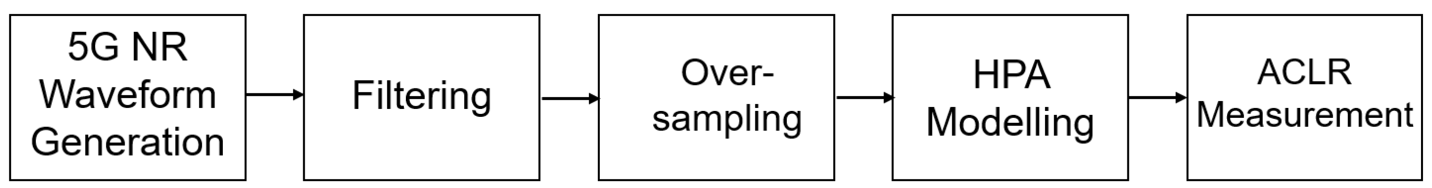
- A filter to mitigate the out-of-band spectral emissions of the 5G waveform has been developed to improve the performance of ACLR;
- The Monte Carlo method has been employed to validate the effectiveness of the proposed guard band protection scheme.
2. Modelling for Guard Band Protection and Analysis
2.1. Mathematical Model for Guard Band Protection
2.2. ACLR
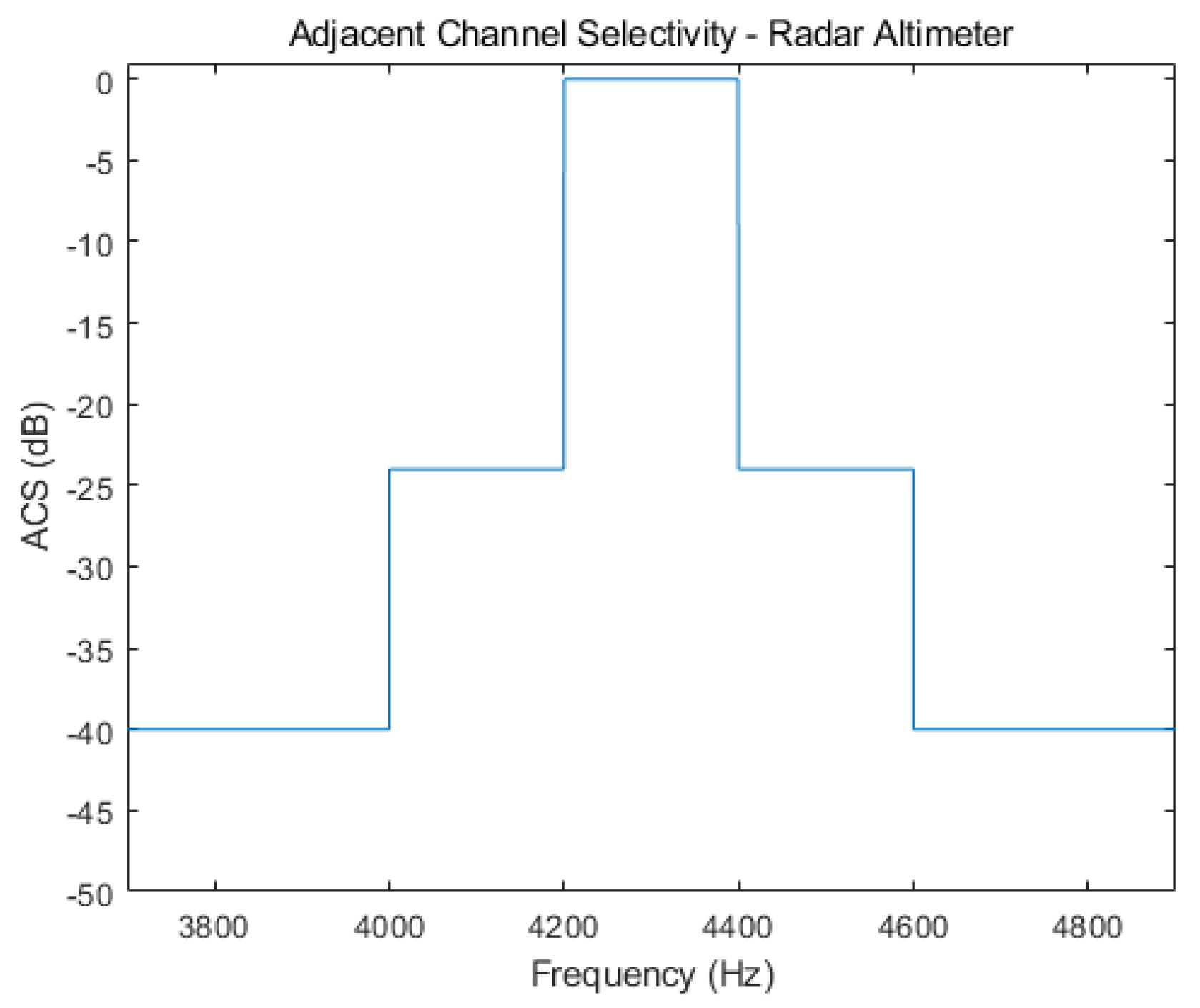
2.3. ACS and ACIR
3. Numerical Results
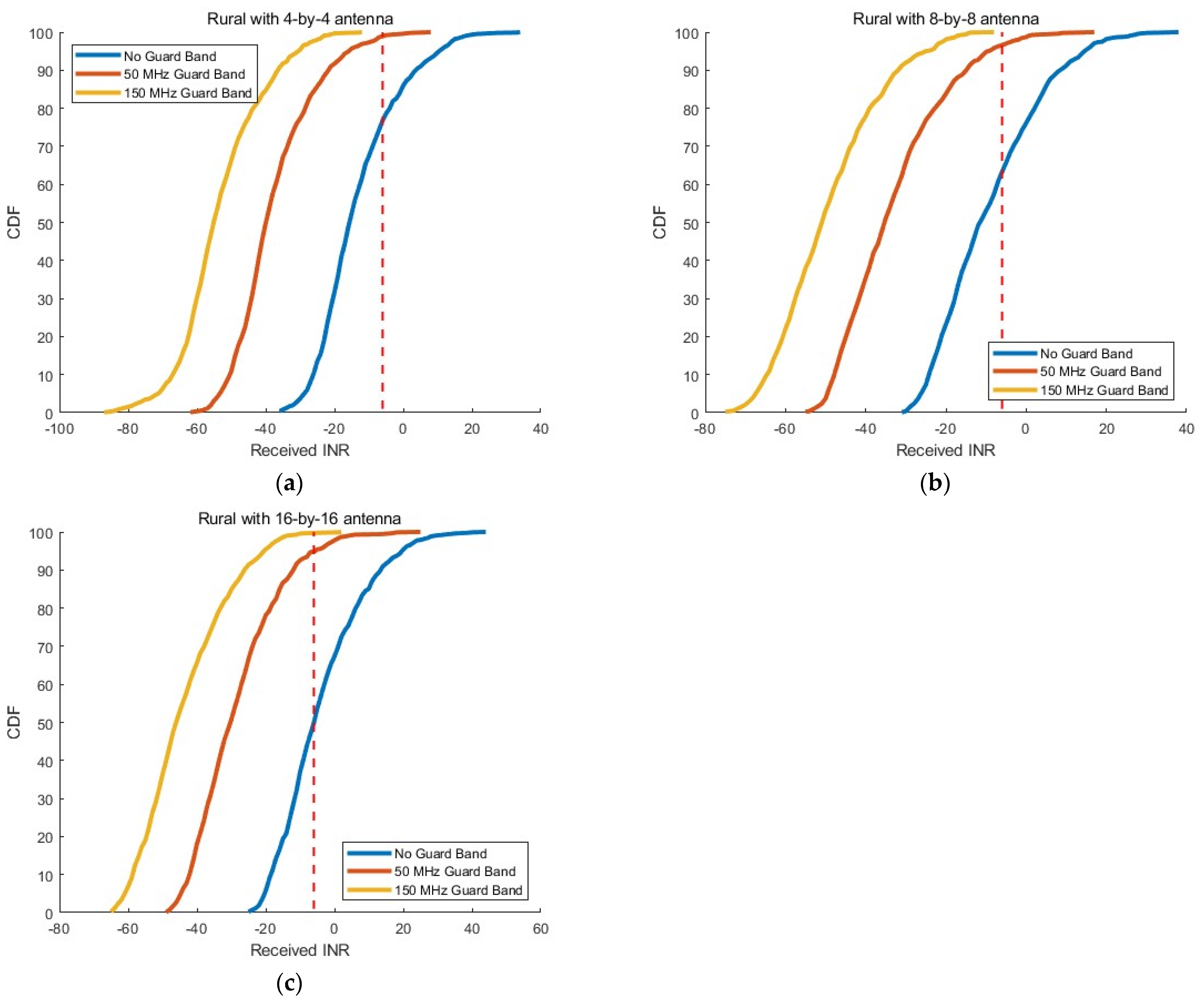
3.1. Rural Areas
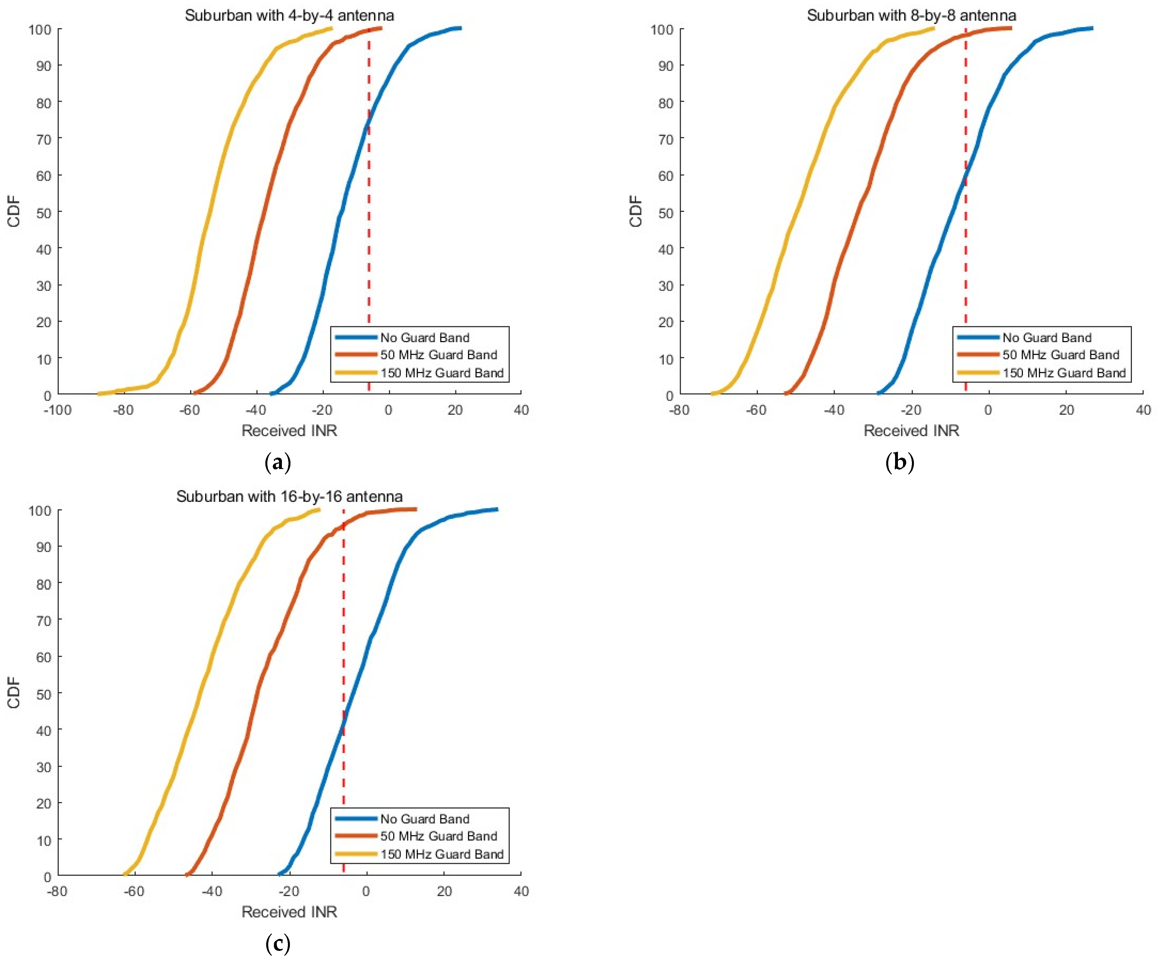
3.2. Suburban Areas
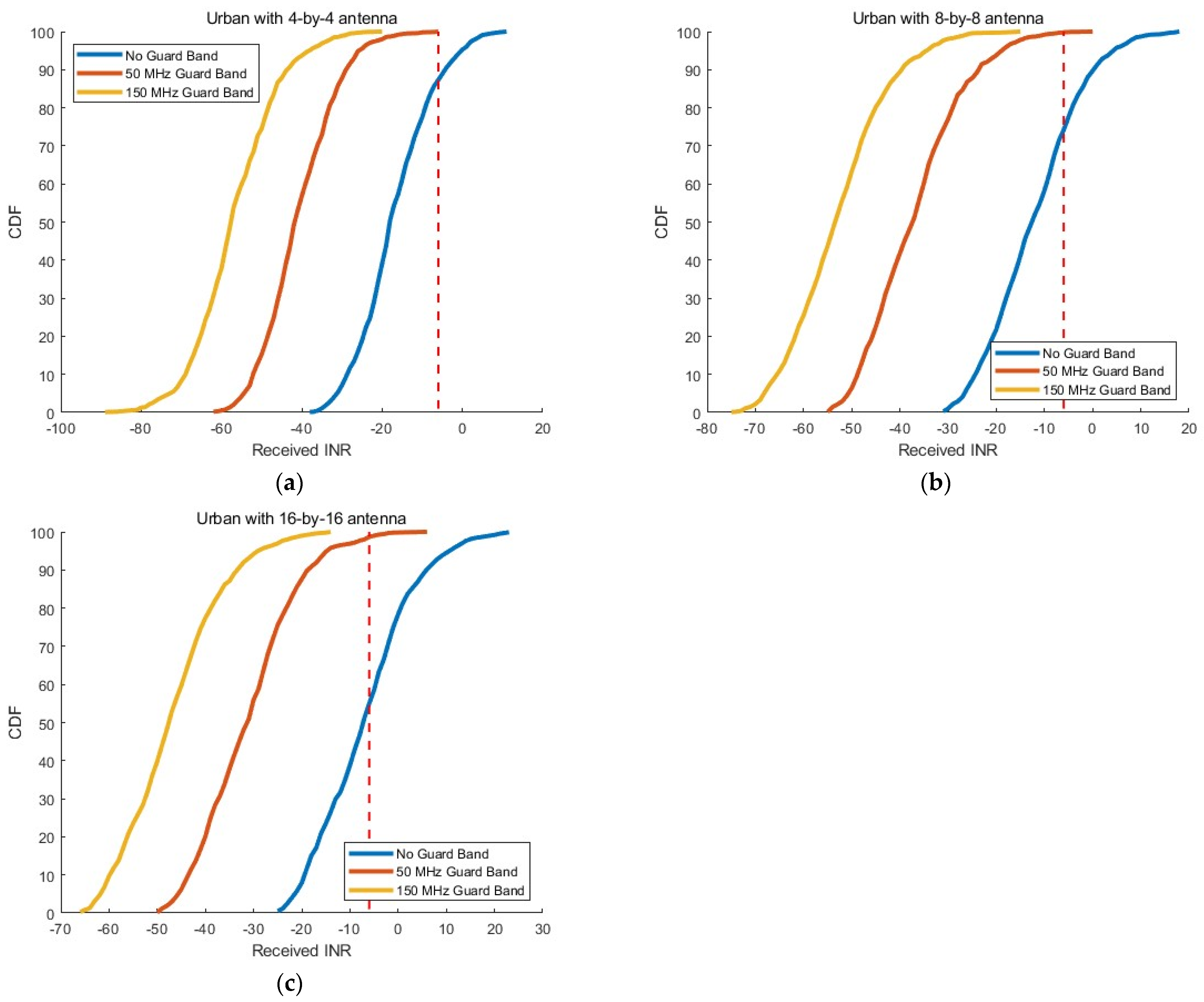
3.3. Urban Areas
4. Conclusions
Author Contributions
Funding
Data Availability Statement
Conflicts of Interest
References
- Dilli, R. Analysis of 5G wireless systems in FR1 and FR2 frequency bands. In Proceedings of the 2020 2nd International Conference on Innovative Mechanisms for Industry Applications (ICIMIA), Bangalore, India, 5–7 March 2020; pp. 767–772. [Google Scholar] [CrossRef]
- Sufian, M.A.; Hussain, N.; Askari, H.; Park, S.G.; Shin, K.S.; Kim, N. Isolation enhancement of a metasurface-based MIMO antenna using slots and shorting pins. IEEE Access 2021, 9, 73533–73543. [Google Scholar] [CrossRef]
- Cho, M.-H. South Korea to Reallocate Mid-Band Spectrum for 5G Use. 28 June 2020. Available online: https://www.zdnet.com/article/south-korea-to-reallocate-spectrum-for-5g-use/ (accessed on 9 September 2024).
- International Telecommunication Union. Operational and Technical Characteristics and Protection Criteria of Radio Altimeters Utilizing the Band 4200–4400 MHz; Document ITU-R M.2059-0; International Telecommunication Union: Geneva, Switzerland, 2014; Available online: https://www.itu.int/dms_pubrec/itu-r/rec/m/R-REC-M.2059-0-201402-I!!PDF-E.pdf (accessed on 5 December 2023).
- Radio Technical Commission for Aeronautics. Assessment of C-Band Mobile Telecommunications Interference Impact on Low Range Radar Altimeter Operations; RTCA Paper No-274-20/PMC-2073; Radio Technical Commission for Aeronautics: Washington, DC, USA, 2020; Available online: https://www.rtca.org/wp-content/uploads/2020/10/SC-239-5G-Interference-Assessment-Report_274-20-PMC-2073_accepted_changes.pdf (accessed on 9 September 2024).
- Singh, R.; Peterson, R.; Riaz, A.; Hood, C.; Bacchus, R.; Roberson, D. A method for evaluating coexistence of LTE and radar altimeters in the 4.2–4.4 GHz band. In Proceedings of the 2017 Wireless Telecommunications Symposium (WTS), Chicago, IL, USA, 26–28 April 2017; pp. 1–9. [Google Scholar] [CrossRef]
- Son, H.-K.; Chong, Y.-J. Interference analysis for compatibility between 5G system and aeronautical radio altimeter. In Proceedings of the 2020 International Conference on Information and Communication Technology Convergence (ICTC), Jeju Island, Korea, 21–23 October 2020; pp. 1553–1556. [Google Scholar] [CrossRef]
- Liu, S.; Li, J.; Hwang, S.-H.; Son, H.-K.; Chong, Y.-J. Interference analysis method for 5G system to radio altimeter. In Proceedings of the 2022 IEEE VTS Asia Pacific Wireless Communications Symposium (APWCS), Seoul, Korea, 24–26 August 2022; pp. 80–84. [Google Scholar] [CrossRef]
- Li, J.; Liu, S.; Lu, H.; Hwang, S.-H. Coexistence of 5G communication systems with radar altimeters. IEEE Access 2024, 12, 32554–32568. [Google Scholar] [CrossRef]
- Corfield, G. Japan Solves 5G Airliner Conundrum: Keep Mobe Masts 200 m From Airport Approach Paths. That’s It. 19 January 2022. Available online: https://www.theregister.com/2022/01/19/5g_airliners_solved_by_japan/ (accessed on 9 September 2024).
- Reardon, M. How the FAA Went to War against 5G. 28 January 2022. Available online: https://www.cnet.com/tech/mobile/how-the-faa-went-to-war-against-5g/ (accessed on 9 September 2024).
- Li, J.; Hwang, S.-H. Adaptive Beamforming Scheme for Coexistence of 5G Base Station and Radar Altimeter. ICT Express, 2024; Submitted. [Google Scholar]
- Chen, W.; Li, M.; Liu, R.; Sun, S.; Chen, M.; Jiang, X. Radio Altimeter Compatibility Analysis with 5G Systems. In Proceedings of the Ninth International Symposium on Sensors, Mechatronics, and Automation System (ISSMAS 2023), Nanjing, China, 11–13 August 2023. [Google Scholar] [CrossRef]
- Bukhari, J.; Mérida, W. 5G Interference with Aviation Altimeters: Technology and Policy Recommendations for Coexistence. Transp. Policy 2024, 153, 1–11. [Google Scholar] [CrossRef]
- Rock, J.; Wang, Y. Radar Altimeter Coexist Design in the 4.2–4.4 GHz Band for Multi-Stage Interference Risk Mitigation in 5G and Beyond. IEEE Aerosp. Electron. Syst. Mag. 2024, 1–10. [Google Scholar] [CrossRef]
- Baylis, C.; Marks, R.J. Solving the 5G Crisis: Enabling Coexistence with Crucial Safety Systems through Adaptivity and Reconfigurability. In Proceedings of the 2022 IEEE Texas Symposium on Wireless and Microwave Circuits and Systems (WMCS), Waco, TX, USA, 19–20 April 2022; pp. 1–5. [Google Scholar] [CrossRef]
- Elsayem, A.; Elghamrawy, H.; Massoud, A.; Noureldin, A. Airborne Safety in The Age of 5G: Assessing The Potential Interference Between C-Band And Aeronautical Radar Altimeter. In Proceedings of the International Archives of the Photogrammetry Remote Sensing and Spatial Information Sciences XLVIII-1/W2-2023, Cairo, Egypt, 2–7 September 2023; pp. 889–894. [Google Scholar] [CrossRef]
- Duan, Z.; Ma, Z.; Bai, J.; Wang, P.; Xu, K.; Yuan, S. Deployment Protection for Interference of 5G Base Stations with Aeronautical Radio Altimeters. Sensors 2024, 24, 2313. [Google Scholar] [CrossRef] [PubMed]
- Liu, S.; Wei, Y.; Hwang, S.-H. Guard Band Protection for Coexistence of 5G Base Stations and Satellite Earth Stations. ICT Express 2023, 9, 1103–1109. [Google Scholar] [CrossRef]
- Pahl, J. The interference calculation. In Interference Analysis: Modelling Radio Systems for Spectrum Management; Wiley: Hoboken, NJ, USA, 2016; pp. 242–244. [Google Scholar]
- International Telecommunication Union. Modelling and Simulation of IMT Networks and Systems for Use Sharing and Compatibility Studies; Document ITU-R M.2101-0; International Telecommunication Union: Geneva, Switzerland, 2017; Available online: https://www.itu.int/dms_pubrec/itu-r/rec/m/R-REC-M.2101-0-201702-I!!PDF-E.pdf (accessed on 6 December 2023).
- Roy, A. Preliminary study into radio altimeter adjacent band compatibility. International Civil Aviation Organization (ICAO). In Proceedings of the 30th Meeting of Working Group F, Aeronautical Communications Panel (ACP), Pattaya, Thailand, 13–19 March 2014; Available online: https://www.icao.int/safety/acp/ACPWGF/ACP-WG-F-30/ACP-WGF30-WP14%20Radio%20Altimeter%20Adjacent%20Bands%20Compatibility%20Study%20with%20IMT-FINAL%20Rev1.docx (accessed on 6 December 2023).
- 3GPP. Study on Channel Model for Frequencies from 0.5 to 100 GHz; Document TR 38.901 V16.1.0, Release 16; ETSI: Sophia Antipolis, France, 2020; Available online: https://www.etsi.org/deliver/etsi_tr/138900_138999/138901/16.01.00_60/tr_138901v160100p.pdf (accessed on 9 September 2024).
- Rohde & Schwarz. Measurement of Adjacent Channel Leakage Power on 3GPP W-CDMA Signals with the FSP. Available online: https://scdn.rohde-schwarz.com/ur/pws/dl_downloads/dl_application/application_notes/1ef41/1EF41_0E.pdf (accessed on 9 September 2024).
- 3GPP. 5G; NR; Base Station (BS) Radio Transmission and Reception; Document TS 38.104 V16.4.0, Release 16; ETSI: Sophia Antipolis, France, 2020; Available online: https://www.etsi.org/deliver/etsi_ts/138100_138199/138104/16.04.00_60/ts_138104v160400p.pdf (accessed on 9 September 2024).
- 5G NR Downlink ACLR Measurement; R2024b MathWorks: Natick, MA, USA. Available online: https://ww2.mathworks.cn/help/5g/ug/nr-downlink-ACLR-measurement.html (accessed on 9 September 2024).
- Futatsumori, S.; Hikage, T.; Nojima, T.; Akasegawa, A.; Nakanishi, T.; Yamanaka, K. ACLR Improvement of a 5-GHz Power Amplifier Using High-Temperature Superconducting Reaction-Type Transmitting Filters. In Proceedings of the 2008 38th European Microwave Conference, Amsterdam, Netherlands, 27–31 October 2008; pp. 1145–1148. [Google Scholar] [CrossRef]
- ANRITSU. 5G NR Sub-6 GHz Measurement Methods: Signal Analyzer MS2850A. Available online: https://dl.cdn-anritsu.com/en-en/test-measurement/files/Application-Notes/Application-Note/ms2850a-5gnr-ef1200.pdf (accessed on 9 September 2024).
- International Telecommunication Union. Characteristics of Terrestrial Component of IMT For Sharing and Compatibility Studies in Preparation for WRC-23; Document ITU-R M.2101-0; International Telecommunication Union: Geneva, Switzerland, 2017. [Google Scholar]
- ICAO. Radio Altimeter Spectrum. 6 February 2018. Available online: https://www.icao.int/NACC/Documents/Meetings/2018/RPG/RPGITUWRC2019-P08.pdf (accessed on 9 September 2024).
- FAA Safety Gov. Maneuvering: Approach and Landing: Chapter 1. Normal Approach and Landing. Available online: https://www.faasafety.gov/files/helpcontent/Courses/ALC-34/content/index.html#/lessons/YjK4Y-m-dXVLSK53f0Tc6bNpxuYYINCy (accessed on 9 September 2024).
- Finlay, M. WestJet Boeing 737 Conducted a Flapless Landing in Deer Lake. 25 July 2020. Available online: https://simpleflying.com/westjet-737-flapless-landing/ (accessed on 9 September 2024).
- Nakamura, S.; Suwa, K.; Morita, A.; Yamamoto, K.; Wakayama, T.; Oshima, T.; Maekawa, R.; Matsuda, A. An experimental study of enhancement of the cross-range resolution of ISAR imaging using ISDB-T digital TV based passive bistatic radar. In Proceedings of the 2011 IEEE International Geoscience and Remote Sensing Symposium, Vancouver, BC, Canada, 24–29 July 2011; pp. 2837–2840. [Google Scholar] [CrossRef]


| Parameters | Unit | Value |
|---|---|---|
| Model | DL-FRC-FR1-QPSK | |
| Channel bandwidth | MHz | 100 |
| Subcarrier spacing | kHz | 30 |
| Duplexing mode | TDD | |
| Cell identity | 1 | |
| Windowing | % | 0 |
| Sampling rate | Hz | 614,400,000 |
| Parameters | Unit | Value |
|---|---|---|
| Carrier frequency | GHz | 3.7–4.0 |
| BS channel bandwidth | MHz | 100 |
| UE channel bandwidth | MHz | 20 |
| BS antenna height | m | Rural: 35 Suburban: 25 Urban: 20 |
| Antenna array | 4 × 4, 8 × 8, and 16 × 16 | |
| Vertical 3-dB beamwidth | ◦ | 65 |
| Horizontal 3-dB beamwidth | ◦ | 90 |
| Vertical element spacing | 0.5λ | |
| Horizontal subarray spacing | 2.1λ | |
| Building height average | m | 5 |
| Body loss | dB | 4 |
| Polarisation loss | dB | 3 |
| Noise temperature | K | 290 |
| Modulation | QPSK [28] | |
| Centre frequency | GHz | 3.95 |
| Front-to-back ratio | dB | 30 |
| Elevation angle | ◦ | [−90, 90] |
| Azimuth angle | ◦ | [−180, 180] |
| Polarisation | ◦ | 45 |
| Duplexing | TDD | |
| Mechanical down tilt angle | ◦ | Rural: 3 Suburban: 6 Urban: 10 |
| Cell radius | m | Rural: 1200 Suburban: 600 Urban: 300 |
| Transmitted power | dBm | Rural: 71 [29] Suburban: 68 Urban: 68 |
| Element gain | dBi | 6.4 |
| UE antenna height | m | 1.5 |
| Parameters | Unit | Value |
|---|---|---|
| Nominal centre frequency | GHz | 4.3 |
| Channel bandwidth | MHz | 196 [30] |
| Carrier frequency | GHz | 4.2–4.4 |
| Maximum antenna gain | dB | 10 |
| Noise figure | dB | 6 |
| Cable loss | dB | 6 |
| −3 dB beamwidth | ◦ | 55 |
| Modulation | FMCW | |
| Landing downward angle | ◦ | 15 [31] |
| Landing speed average | m/s | 74.588 [32] |
| Fuselage length | m | 39.5 [33] |
| Interference protection criteria | dB | −6 |
| Environment | Antenna Array | Received Interference (dB) |
|---|---|---|
| Rural | 4 × 4 8 × 8 16 × 16 | 34.3446 40.3652 46.3858 |
| Suburban | 4 × 4 8 × 8 16 × 16 | 22.3548 28.3754 34.396 |
| Urban | 4 × 4 8 × 8 16 × 16 | 12.0633 18.0839 23.6751 |
Disclaimer/Publisher’s Note: The statements, opinions and data contained in all publications are solely those of the individual author(s) and contributor(s) and not of MDPI and/or the editor(s). MDPI and/or the editor(s) disclaim responsibility for any injury to people or property resulting from any ideas, methods, instructions or products referred to in the content. |
© 2024 by the authors. Licensee MDPI, Basel, Switzerland. This article is an open access article distributed under the terms and conditions of the Creative Commons Attribution (CC BY) license (https://creativecommons.org/licenses/by/4.0/).
Share and Cite
Li, J.; Hwang, S.-H. Guard Band Protection Scheme to Facilitate Coexistence of 5G Base Stations and Radar Altimeters. Electronics 2024, 13, 3681. https://doi.org/10.3390/electronics13183681
Li J, Hwang S-H. Guard Band Protection Scheme to Facilitate Coexistence of 5G Base Stations and Radar Altimeters. Electronics. 2024; 13(18):3681. https://doi.org/10.3390/electronics13183681
Chicago/Turabian StyleLi, Jiaqi, and Seung-Hoon Hwang. 2024. "Guard Band Protection Scheme to Facilitate Coexistence of 5G Base Stations and Radar Altimeters" Electronics 13, no. 18: 3681. https://doi.org/10.3390/electronics13183681
APA StyleLi, J., & Hwang, S.-H. (2024). Guard Band Protection Scheme to Facilitate Coexistence of 5G Base Stations and Radar Altimeters. Electronics, 13(18), 3681. https://doi.org/10.3390/electronics13183681