Abstract
A platform for indoor monitoring inside buildings, integrating both conventional and environmentally friendly devices with energy-harvesting sources, is proposed. Biomaterials such as gelatin and chitosan, derived from renewable resources, have been utilized to fabricate hydrogel and active layers for sensors and supercapacitors. These devices enhance the environmental profile of the proposed solution by employing sustainable materials and optimizing energy consumption. The developed electronic board prototype provides a versatile platform for testing various sensor configurations while accommodating different energy-harvesting sources. The article details the design of an energy harvesting system for indoor monitoring, covering various aspects regarding energy sources, power management circuits, and low-power microcontroller units. It examines energy storage devices and sensors, including both eco-friendly and commercial ones, as well as radio transceivers with different communication technologies. Additionally, an energy analysis to evaluate the performance and energy efficiency of the platform is presented.
1. Introduction
The buildings sector is a significant consumer of energy worldwide, accounting for approximately 34% of final energy consumption [1]. This substantial energy usage is largely attributed to heating, ventilation, and air conditioning (HVAC) systems, which are essential for maintaining indoor comfort and air quality [2,3]. As concerns about climate change and energy sustainability intensify, there is an increasing imperative to address the energy demands of the building sector [4]. In response to these challenges, the European Union (EU) has set ambitious goals to decarbonize its building stock by 2050. This initiative aims to reduce greenhouse gas emissions and promote energy efficiency, ensuring that buildings are not only environmentally sustainable but also enhance occupant comfort and health. The strategy of the EU emphasizes the development of energy-efficient buildings that are interconnected, leveraging smart technologies to optimize energy use and improve indoor environmental quality [5].
Significant advancements in building design, construction, and operation are necessary to achieve these goals. Energy efficiency has become a critical factor in reducing emissions and limiting global temperature rise. This priority has been highlighted at COP28, where parties are committed to doubling the annual rate of energy efficiency improvements from around 2% to over 4% until 2030. Such measures significantly impact the energy consumption building sector [6]. The EU has implemented the Energy Performance of Building Directive (EPBD, Directive 2024/1275) to support the transition to smart, automated, and energy-efficient buildings that enhance occupant comfort and health. The revised EPBD also emphasizes maintaining a healthy indoor climate, considering that Europeans spend over 90% of their time indoors.
Interconnected devices play a vital role in optimizing HVAC systems and enhancing energy efficiency in buildings. However, the rapid growth of the Internet of Things (IoT) introduces additional challenges, particularly concerning electronic waste management. With the number of IoT devices is expected to reach one trillion by 2035, the environmental impact of these technologies—including the frequent need for battery replacements—raises significant concerns [7]. Large-scale Wireless Sensor Networks (WSNs), comprising numerous IoT devices, can also lead to high maintenance costs, potentially making them economically unsustainable.
Addressing these challenges, this paper aims to contribute to the development of sustainable building practices that align with global and regional energy and climate targets. This study presents a platform for indoor monitoring, designed to capture unused indoor energy sources and convert them into power for environmental sensors, thereby creating a self-powered WSN node. This platform leverages photovoltaics for energy harvesting and utilizes eco-friendly supercapacitors and sensors for storage and sensing. These innovations aim to develop efficient environmental monitoring systems that support sustainable energy management, enable real-time adjustments based on ambient conditions, and ultimately improve energy efficiency and reduce carbon footprints in smart buildings and other applications.
It is clear that, at the current level of development, energy sources, energy storage, and sensors based on eco-friendly and sustainable materials do not perform as well as their traditional counterparts in terms of efficiency, size, and durability. However, the aim of this work is to show, at a demonstrator level, the feasibility of a self-sustained indoor environmental sensing and monitoring system based on such “novel” materials and technologies. Given the limited amount of available energy in the indoor environment, the challenge is to develop a system that can perform useful tasks, such as environmental sensing and remote data transmission, while employing “green” components, in a self-sustainable manner.
In this study, the following topics will be explored: (i) design of a platform for energy harvesting and monitoring in building applications, (ii) improvement in the environmental profile of IoT solutions using sustainable materials and optimizing energy consumption, and (iii) preliminary energy analysis of the main components to assess system feasibility.
2. Energy Harvesting System Design
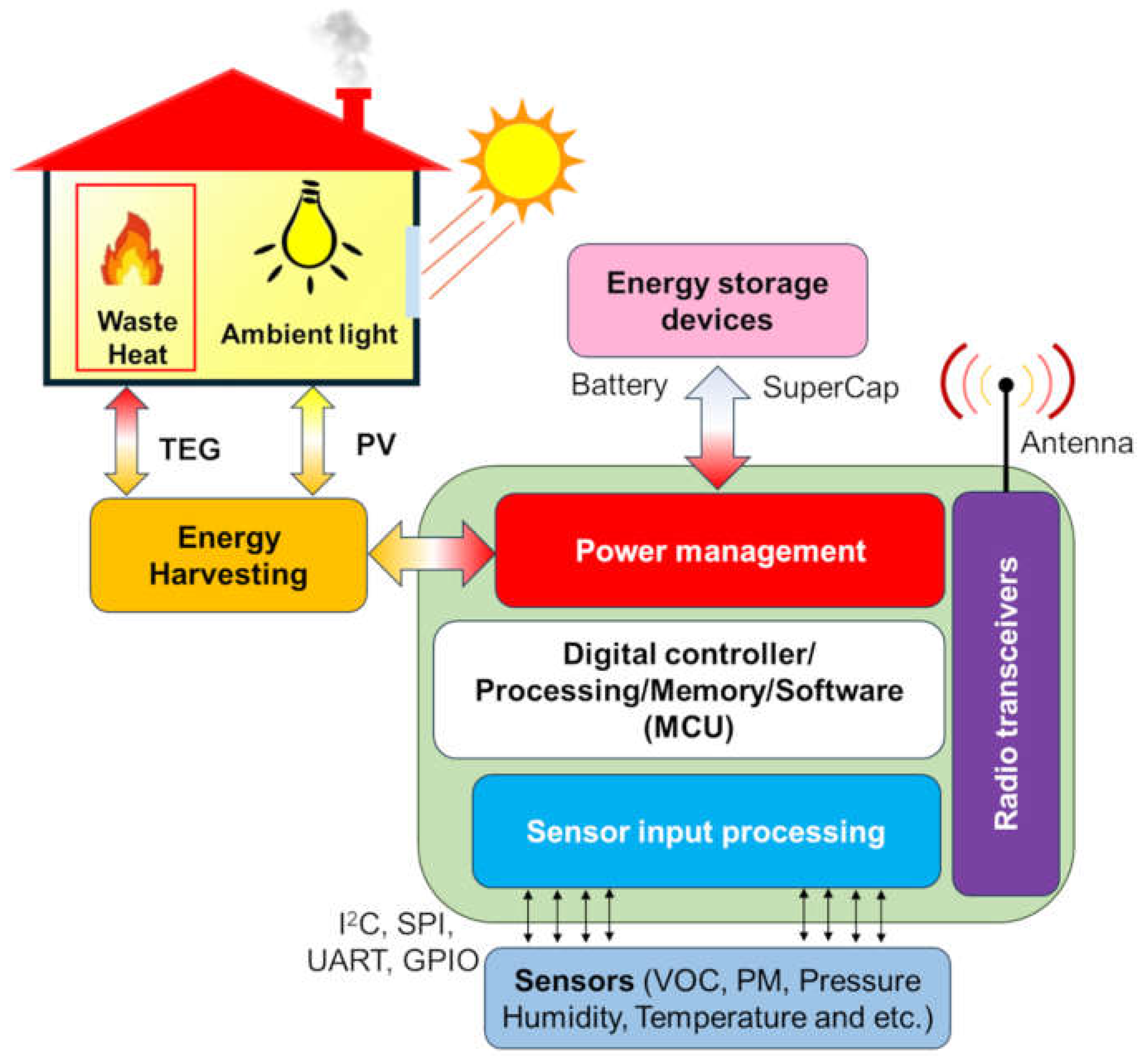
Energy harvesting is the process of capturing energy from ambient sources (e.g., solar, thermal, or mechanical vibrations) and then storing it for use in powering small electronic devices [8,9,10]. This technology promises a sustainable and self-sufficient energy solution, particularly for low-power applications such as sensors [9], wearable devices [10], and remote monitoring systems [8,11]. In Figure 1, a schematic picture of the main components of an energy harvesting system is shown. As can be observed, the energy-harvesting system for indoor monitoring that transmits data comprises several key components. Firstly, it captures ambient energy using harvesters (e.g., solar cells, thermoelectric, piezoelectric, or triboelectric generators), which is then converted and regulated by power management circuits. Subsequently, supercapacitors and batteries store the harvested energy to ensure consistent power. A low-power microcontroller (MCU) processes data and oversees the functions of the node controlling the low-power sensors, either eco-friendly or commercial, to measure environmental parameters. Finally, the MCU controls the radio transceivers that wirelessly transmit the collected data to a remote station or other devices [12,13]. In such a system, it is fundamental to appropriately manage the amount of harvested energy in consideration of the energy consumption associated with sensing, computation, and data transmission. Energy harvesters (EHs) are crucial for providing the necessary power to operate IoT nodes, with energy and power requirements varying based on the specific application, electronics technology, and wireless communication protocol employed. These requirements can range from micro-watts (µW) to watts (W). Additionally, reliability is a key aspect, as EHs must consistently supply energy to meet the demands of the associated electronics of the IoT node. This reliability is challenged by potential fluctuations in the energy source over time. To mitigate this, a harvest–store–use architecture can decouple the electronics from these fluctuations. However, relying on predictable energy sources—such as indoor lighting—ensures more consistent operation.

Figure 1.
Schematic picture of the main components of an energy harvesting system.
The following discussion covers the selection of energy sources, the design of energy conversion circuits, and the integration of storage components.
2.1. Energy Harvesters
The indoor energy harvesting technologies show a power generation range between a few tens nW/cm2 up to hundreds of µW/cm2 [7,14,15,16,17,18]. More in detail, thermoelectric (TEGs) and piezoelectric (PEGs) generators provide medium energy reliability depending on specific conditions, such as the proximity to a thermal source for TEGs and the need for mechanical actuation for PEGs. The power density for TEGs ranges from 10 nW to 60 µW/cm2, while for PEGs, it spans 100 nW to 900 µW/cm2, with output highly dependent on actuation specifications [14]. Triboelectric nanogenerators (TENGs) also require actuation and have similar medium reliability, but they offer a broader range of power density, from 400 nW to 50 mW/cm2 [15]. Ambient RF energy harvesters stand out for their high energy reliability and deployability, thanks to the ubiquity of RF signals in urban environments, although they have a lower power density range of 20–300 nW/cm2 [16]. Indoor photovoltaic (PV) systems are noted for their high energy reliability and deployability, providing a predictable and controllable energy source that is widely available. Their power density ranges from 3 to 100 µW/cm2, making them a versatile and efficient option for various indoor applications [17,18].
Among these energy harvesters for indoor applications, photovoltaic cells (PV) and thermoelectric generators (TEGs) are more favorable in terms of energy generation, deployability, and cost-effectiveness. Photovoltaic cells, commonly associated with outdoor illumination, can also be adapted for indoor use by capturing artificial light. Indoor illumination typically has much lower intensities and narrower spectra compared to sunlight, ranging from several mW/m2 to a few W/m2. Common indoor light levels are around 200 to 500 Lux in private areas and 500 to 1500 Lux in office and industrial settings [19]. Additionally, there is a wide variety of lamp types, including sodium discharge, fluorescent, incandescent bulbs, LEDs, and halogen lamps, each with distinct spectral distributions and radiometric power densities [20,21].
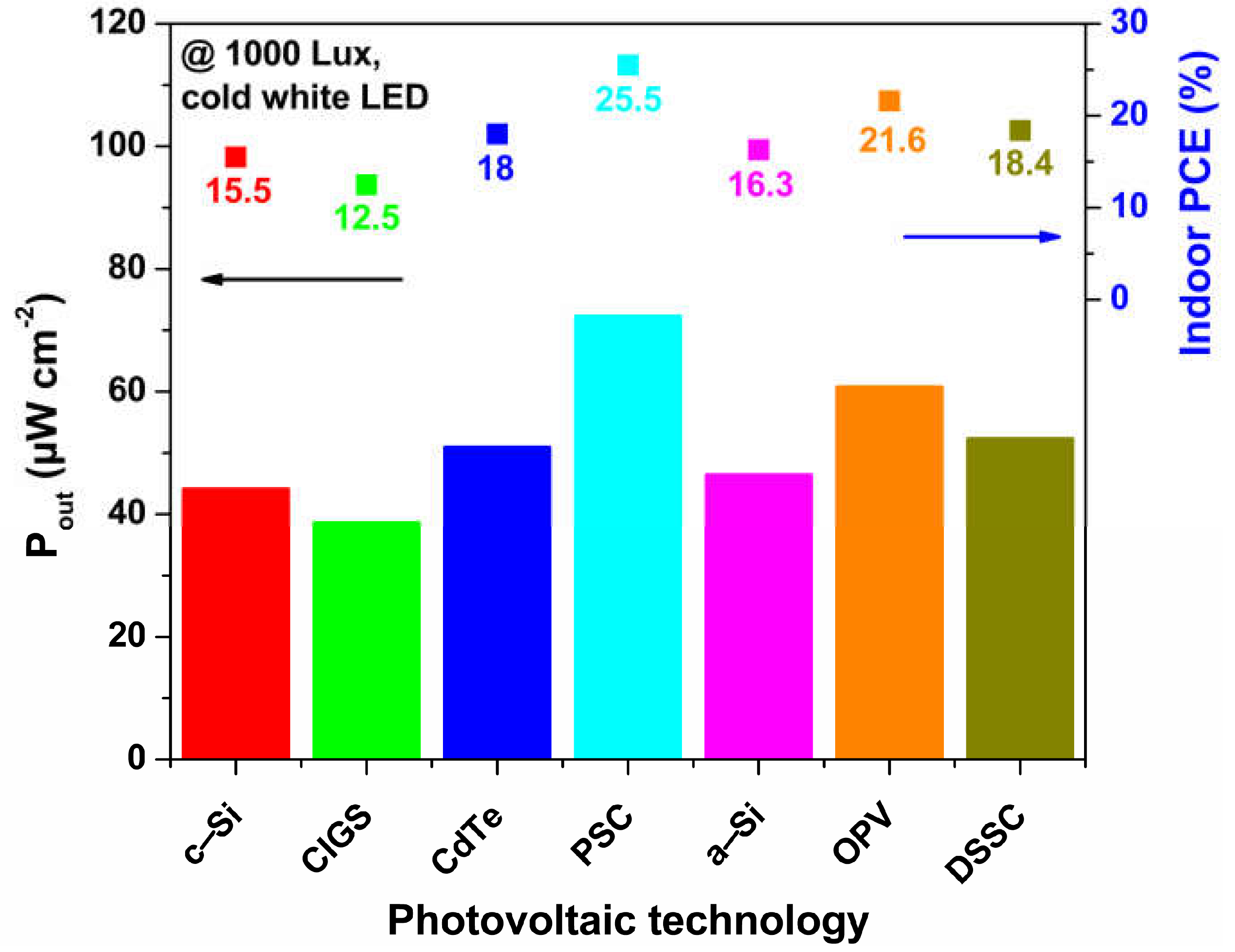
Currently, there are several available PV technologies, having different energy densities, power conversion efficiencies, and costs. In Figure 2, for each PV technology, the values of power conversion efficiency and output power density at a reference illumination of 1000 Lux (obtained with a cold white LED source) are reported [19]. Crystalline silicon (c-Si) dominates the outdoor solar cell market, accounting for about 97% of the share [22]. For indoor applications, amorphous silicon (a-Si) is commercially more suitable, achieving higher efficiencies of up to 16.3% under indoor lighting conditions [19]. Thin-film technologies, such as copper indium gallium selenide (CIGS) and cadmium telluride (CdTe), make up the remaining market share, with indoor power conversion efficiencies (PCE) ranging from 12.5% to 18%.

Figure 2.
Comparison of different photovoltaic technologies. For each technology the output power density and indoor power conversion efficiency at a reference illumination of 1000 Lux is reported, obtained with a cold white LED source.
Emerging technologies such as dye-sensitized solar cells (DSSCs), organic photovoltaics (OPVs), and perovskite solar cells (PSCs) are also being considered as cost-effective and sustainable hybrid alternatives to traditional solid-state solar cells.
As evident in Figure 2, PSCs and DSSCs have the higher values of indoor power conversion efficiency of 25.5% and 18.4%, respectively. In particular, the unique material properties of perovskites [23], such as their high absorption coefficients, lower recombination kinetics [24], and tunable bandgaps [25,26], enable PSCs to efficiently convert a broad spectrum of light, including the wavelengths typical of indoor lighting. Furthermore, the ability to produce PSCs on flexible substrates allows for the integration of these solar cells into a variety of indoor surfaces and objects, enhancing their practicality and esthetic appeal. This flexibility, combined with their low production costs and high indoor PCE values [27], positions PSCs as a promising technology for large-scale, low-cost, and autonomous indoor energy solutions. Finally, the output power density of all considered PV technologies ranges from 40 µW/cm2 to 80 µW/cm2, which is several orders of magnitude lower compared to the power densities observed for these devices under outdoor illumination.
Thermoelectric generators capitalize on temperature differences between surfaces to generate electrical power. In indoor settings, TEGs can harness waste heat from appliances, electronics, and even human body heat. This capability makes them a versatile and reliable energy source, particularly in locations where temperature gradients are readily available. However, TEGs have a very low energy conversion capability, which implies that, to generate enough electric power, they require a significant heat flux. This implies the need for a warm or cold surface that can exchange a large amount of heat with the environment. The advantages of TEGs for indoor use extend beyond their energy conversion capabilities. They are solid-state devices with no moving parts, which ensures a high level of durability and minimal maintenance [28]. Additionally, their compact size and ability to operate silently make them ideal for integration into various indoor environments without causing disruption.
In the present study, indoor PV systems are chosen for their high energy reliability, predictable performance, and ease of integration. In contrast to other technologies, PV systems deliver consistent power density and are independent of specific conditions or mechanical actuation, making them a versatile and cost-effective solution for indoor energy harvesting.
2.2. Power Management Circuits for Energy Harvesting
Power management circuits for energy harvesting are critical components in the development of a self-powered electronic board prototype for indoor monitoring, converting ambient energy from sources, such as light and heat, into usable electrical power by using energy harvesters [29]. These circuits are predominantly designed as integrated circuits (ICs) with a compact form factor and employ complementary metal–oxide–semiconductor (CMOS) technology to minimize quiescent current (IQ). This design approach is essential for enhancing the efficiency and reliability of energy harvesting systems, ensuring that the harvested energy is effectively stored and utilized [30].
Key parameters in the design and performance of power management circuits for energy harvesting include cold-start voltage and power, efficiency, and leakage current. It is worth noting that minimizing quiescent or leakage current is essential for harvesting low-power-density energy sources, such as RF and thermal energy. In contrast, voltage and current regulation are critical factors for managing high-voltage or high-current energy sources, such as piezoelectric and solar power sources [31]. Typical values for some representative chips available on the market are reported in Table 1.

Table 1.
List of commercial energy harvesting integrated circuits for different energy sources.
Cold-start voltage and power refer to the minimum voltage and power levels required for the circuit to begin operation. This parameter is crucial for ensuring that the system can initialize and start harvesting energy from a sleep state, particularly in environments where the energy source is intermittent or weak. Efficiency is a measure of how effectively the circuit converts harvested energy into usable electrical power while minimizing losses. High efficiency is essential to maximize the available energy and extend the operational lifespan of the powered device, especially in low-energy environments. Leakage current represents the unwanted flow of current within the circuit when it is not actively converting or storing energy. Minimizing leakage current is important to prevent energy loss, which can significantly impact the overall performance and efficiency of the energy harvesting system.
As shown in Table 1, the AEM10330 from e-peas S.A. and the EM8500 from EM Microelectronic both feature cold-start voltages around 300 mV, offering over 80% efficiency for input voltages (Vin) above 1 V, making them well-suited for solar and thermal energy applications. The LTC3108, from Analog Devices, has an impressively low cold-start voltage of 20 mV, though with an external transformer and a lower efficiency of less than 40%, making it suitable for thermal energy harvesting. The MAX17220 from Maxim Integrated stands out for its high efficiency (>90%) and low leakage current, making it compatible with RF, solar, and thermal energy sources. Finally, the SPV1050 from STMicroelectronics and the Bq25505 from Texas Instruments provide efficient operation with cold-start capabilities at higher voltages, suitable for a variety of energy sources, including solar and thermal. It is worth noting that most commercially available energy-harvesting chips are designed to function as chargers for batteries or supercapacitors. This harvest–store–use architecture effectively isolates the electronics from energy fluctuations, particularly those from ambient sources, thereby ensuring more reliable operation of the IoT node through reliance on a stable and predictable energy source [7]. After evaluation of the characteristics of several energy-harvesting integrated circuits, the e-peas AEM 10330 was chosen for the development of an energy-harvesting electronic test board.
2.3. Energy Storage Devices
Energy storage devices play a crucial role in modern energy harvesting systems, enabling the efficient storage and release of energy scavenged for the operation of the developed electronic board prototype for indoor monitoring. They support the operation of sensors, front-end electronics, data processing, and communication with a base station. Several types of technologies exist, each with distinct characteristics and advantages. More in detail, the attention can be focused on supercapacitors and batteries. Supercapacitors (SCs) store energy through electrostatic charge rather than chemical reactions [32]. They provide rapid charge and discharge capabilities, high power density, and long cycle life, being ideal for applications requiring quick bursts of energy (e.g., ≪1 s) typical of IoT nodes [33,34]. Electrochemical batteries, such as lithium-ion (Li-ion), lead–acid, and solid-state batteries, are the most widely used energy storage devices. They offer high energy density, efficiency, and versatility, making them suitable for portable and stationary applications. Advances in battery technology focus on improving energy density, cycle life, and safety while reducing costs [35].
With the number of IoT nodes projected to reach one trillion interconnected devices by 2035 [7,36], managing the environmental impact of this technology poses a significant challenge, particularly concerning the electronic waste generated. Each IoT node is powered by a battery that requires frequent replacement or recharging. This becomes even more problematic if the nodes are placed in hard-to-reach locations, fully sealed, or embedded in architectural elements and infrastructures within buildings [7]. Additionally, WSNs with many IoT nodes can lead to high maintenance costs, making them economically unsustainable. The use of lithium-ion batteries adds to the issue, as they rely on toxic and scarce materials like lithium, cobalt, nickel, and manganese, whose extraction has substantial environmental consequences [37]. To address these concerns, some studies are exploring more environmentally friendly batteries, though these alternatives currently offer lower energy performance and cycle stability compared to mainstream technologies [38]. To mitigate the environmental impact, the proposed prototype uses a supercapacitor and sensor made from materials sourced from renewable resources [39,40].
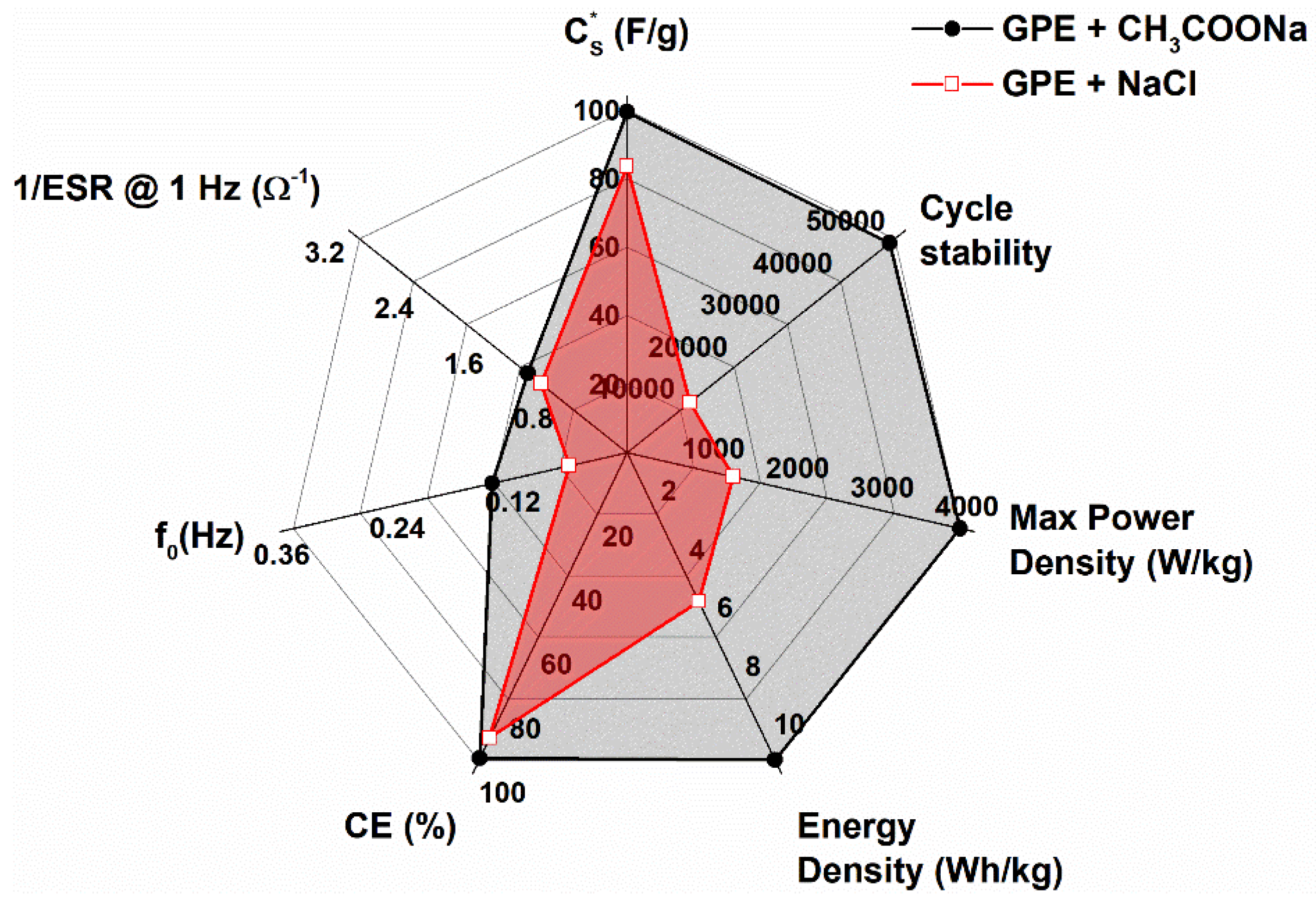
The proposed electronic test board uses a low-cost environmentally friendly SC (1 F of capacitance), Li-ion battery, and combinations of both. To realize the SC, symmetric carbon-based SCs with biodegradable polymers employed in the electrode binder (chitosan from shrimp shells) and hydrogel systems (gelatin from bovine skin) have been considered. Different types of gel polymer-based (GPE) composites, which contain sodium acetate (CH3COONa), or reference GPE composites with NaCl have been utilized [39,41]. The experimental data shown in Figure 3 as a radar plot comparing the dielectric properties of the two kinds of SCs considered indicates that the GPE supercapacitor with sodium acetate possesses superior energy performance and cycle stability [40,42].

Figure 3.
Performance comparison of gel polymer-based (black full circles) supercapacitors versus reference gel polymer electrolytes (red open circles) with chitosan as electrode binder.
For the meaning of the quantities in Figure 3 see [40]. In particular, the addition of acetate (GPE + CH3COONa) extends the operational lifespan of up to 50,000 cycles, improves the specific energy density to 10.6 kWh/kg, and gives a gravimetric capacitance value of approximately 100 F/g.
In the developed solar-powered energy harvesting solutions, the limited energy storage capacity of gel polymer-based supercapacitors necessitates their association with a small Li-ion polymer battery (3.7 V, 40 mAh, corresponding to 530 J of storable energy). The battery activates when the energy source to be harvested is missing or the supercapacitor is depleted, thus providing the necessary energy to the sensing, processing, and communication circuitry.
2.4. Low-Power Microcontroller Unit
Low-power microcontroller units (MCUs) are pivotal in the advancement of energy-efficient electronics, especially in applications requiring long battery life and minimal energy consumption. These MCUs are designed to perform a variety of tasks with minimal power usage, making them ideal for a wide range of applications, including the IoT sensors here described. Typical parameters for chips available on the market are reported in Table 2 in terms of maximum frequency, memory types, current consumption, and working voltage [43].
Table 2.
Some low-power MCUs available on the market.
Key features of low power MCUs include optimized power consumption modes, efficient processing capabilities, and advanced power management techniques. These microcontrollers can operate in ultra-low power states when not actively processing tasks, significantly reducing energy usage. Additionally, they incorporate power-efficient peripherals and integrated circuits to further minimize power consumption during operation. By minimizing power draw, low-power MCUs prolong the operational life of battery-powered devices, reducing the need for frequent battery replacements or recharges. Their low power requirements make these MCUs well-suited for devices powered by energy harvesting systems, which typically generate small amounts of energy from ambient sources. Moreover, advanced power management features allow these MCUs to dynamically adjust their power states based on workload demands, optimizing overall energy efficiency.
Among the chips reported in Table 2, the one chosen for the realization of the electronic test board described here is the model ESP32–S3, manufactured by Espressif Systems, although the current consumption value is higher when compared with the others shown in Table 2. The choice was driven by its large memory, integrated Wi-Fi and BLE support, large number of general purpose I/O pins that can perform a wide range of functions (SPI, I2S I2C, PWM, ADC, UART, etc.), and ease of coding. The support for multiple development environments, extensive documentation, a rich library ecosystem, strong community support, and the availability of scripting languages are factors that make the ESP32–S3 an accessible and versatile platform for the developers of the electronic test board.
2.5. Sensors (Low-Power Eco-Friendly and Commercial)
For energy harvesting applications in indoor building monitoring, the selection of sensors is crucial for efficient data collection and effective energy management. Several factors must be considered when deploying sensors to measure parameters such as CO2, humidity, temperature, and ambient light. Since these systems are powered by harvested energy, it is vital to choose sensors with low power consumption, preferably those with ultra-low power modes or sleep functions, to extend the operational lifespan between energy harvesting cycles. Additionally, the sensors must provide precise and reliable data. For example, CO2 sensors should have high sensitivity and quick response times to accurately detect changes in carbon dioxide levels, indicating air quality and ventilation efficiency. Similarly, humidity and temperature sensors must offer accurate readings of environmental conditions, which are critical for HVAC systems to optimize energy use and ensure comfort. Ambient light sensors not only monitor lighting conditions for energy harvesting purposes but also help optimize artificial lighting, contributing to energy conservation efforts. Table 3 lists the selected low-power commercial sensors for indoor monitoring used in the developed electronic test board.
Table 3.
List of low-power sensors used for indoor monitoring. The reported low-cost eco-friendly temperature sensor is developed by ENEA.
These sensors collectively form an efficient environmental monitoring system that supports sustainable energy management by enabling real-time adjustments based on ambient conditions, ultimately enhancing energy efficiency and reducing carbon footprints in smart buildings and other applications.
To further enhance the sustainability of the developed solution, the temperature sensor referred to as Bio-Therm in Table 3 has been developed using a hydrogel material composed of gelatin (derived from porcine skin) and graphene [44]. The utilization of such natural biomaterial serves to reduce the environmental impact, thus representing a valuable alternative to the potential escalation of electronic waste due to the proliferation of commercial and polluting IoT devices. This bio sensor features a temperature sensitivity of approximately −19 mV/K, a response time ranging from 30 to 150 s, and a low energy consumption of less than 15 µWh. It can detect ice formation and has demonstrated long-term stability over two years. Moreover, aged sensors can be effectively regenerated with a few drops of water, increasing the sustainability and reusability of Bio-Therm devices [45].
For the developed electrochemical temperature sensor, a special driving circuit is required to reduce voltage drift and offset the output voltage signal. The designed circuit allows for a measurement every 10 min, consisting of a 6 min idle period where the device is electrically shorted and a 4 min sensing period during which the device is biased with a constant current of 15 µA. This approach helps maintain the accuracy and reliability of sensor readings while minimizing energy consumption [44].
2.6. Radio Transceivers
The data collected from the environmental sensors, as well as other useful system data, such as battery charge level, etc., need to be transmitted to a remote station for further processing and/or for the detection of abnormal situations. This part can be quite energy “costly”, as signal transmission is omnidirectional in typical applications, thus decreasing in amplitude with the inverse square distance law. Therefore, the choice of a proper transmission technology is a very crucial aspect.
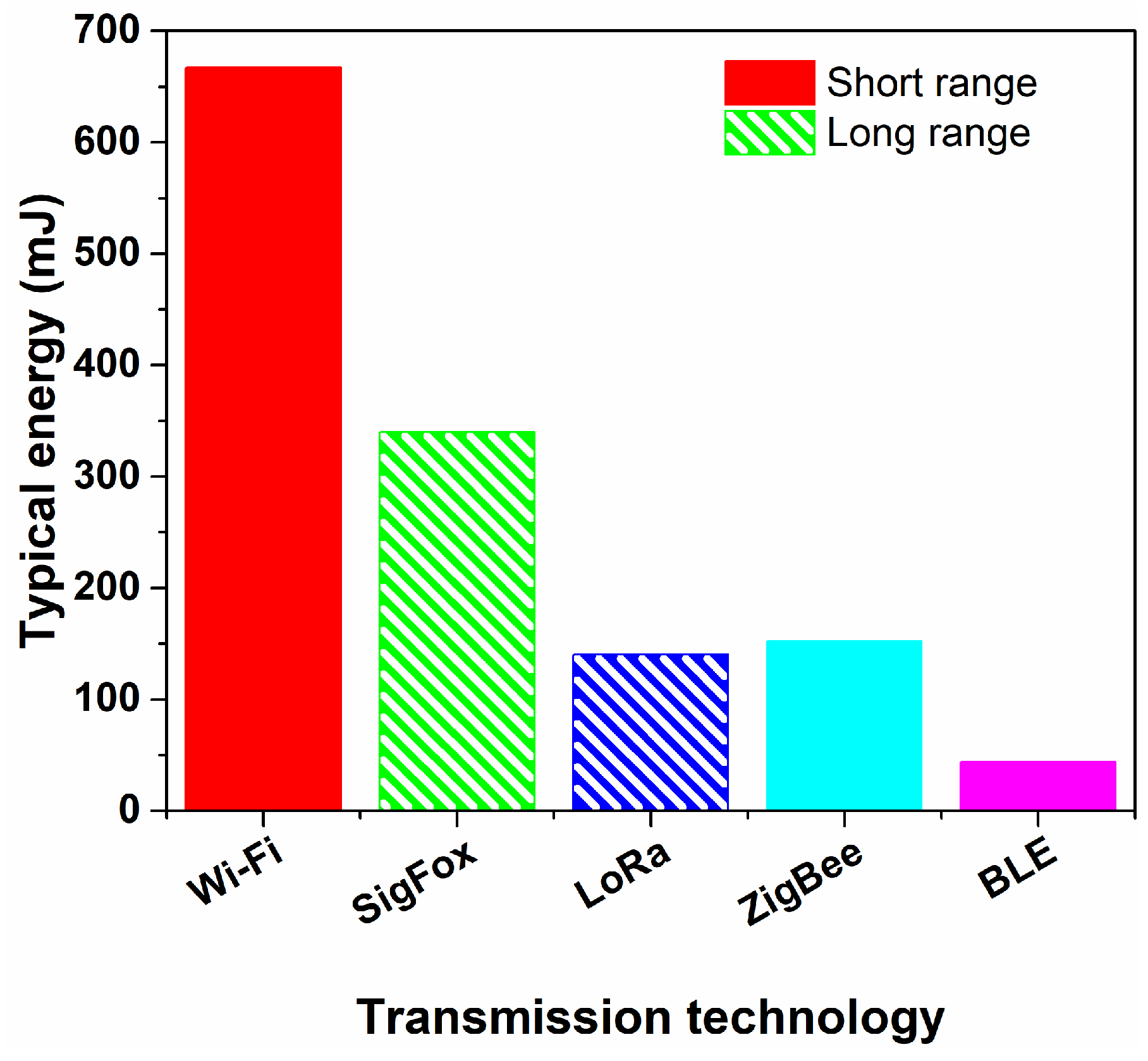
In Figure 4, different technologies are compared; for details, see [18] and references therein. Wi-Fi has a very high speed but at the cost of rather large energy consumption and a medium-to-short range (<50 m). All the other listed technologies are low power. BLE and Zigbee are short-range (<20 m). Sigfox and LoRa all have long range, more than 10 km in open air, and relatively low power. This makes them particularly suited for indoor applications, where it is reasonable to assume that a single gateway will receive the data from sources scattered inside the building and separated by many walls. In terms of energy balance and the possibility to cover higher distances it is, therefore, evident that the choice should be made on one of these last two technologies. Additionally, in typical IoT applications, the data to be transferred amount to few bytes. Therefore, most of the energy is spent on establishing the connection with the gateway. By developing a simplified transmission protocol, it is then possible to significantly reduce the energy budget for data transmission. The basic requirements of a transmitted data packet are (i) node identification, (ii) sensor values, and (iii) system status. Additionally, a layer of security can be added as checksum and data encryption. If necessary, and depending on the specific applications, an acknowledgement of correct receival of the data can be sent by the gateway. This would, however, increase the energy consumption of the transmitting node. The availability of different transceiver chips and user-friendly software libraries was the determining factor for the choice of the LoRa communication protocol for the electronic test board.

Figure 4.
Energy consumption associated with the transmission of a 12-byte packet using different transmission technologies.
2.7. Criteria for Technology Selection, Indoor Conditions, and Scalability
PV systems have been selected as the primary technology for indoor energy harvesting due to their high energy reliability, predictable performance, and ease of integration. Unlike TEGs, which require significant temperature gradients, or PEGs and TENGs, which depend on mechanical actuation, PV systems provide consistent power output as long as ambient light is present. This makes them more versatile and suitable for a wide range of indoor applications, where artificial lighting is commonly available. Additionally, PV technologies are cost-effective, owing to their mature market and well-established production methods, offering an optimal balance between performance and affordability.
The power management circuits have been chosen based on their efficiency in converting and regulating the energy harvested from PV systems. The main criteria included the following: (i) ease of integration with PV technology, (ii) high conversion efficiency, and (iii) the ability to function effectively at the low power levels typically encountered in indoor environments. These circuits have also been selected for their capacity to minimize energy losses during conversion and storage, ensuring that the maximum possible energy could be utilized for the application.
For energy storage, components have been selected to balance storage capacity, sustainability, cost, and durability. Gel polymer-based supercapacitors have been chosen for their fast charge–discharge cycles and robustness. However, due to their limited energy storage capacity, they have been paired with a small Li-ion polymer battery to ensure sufficient storage (3.7 V, 40 mAh, corresponding to 530 J of storable energy). This combination allows for efficient energy storage, addressing both the immediate and long-term energy needs of the system while maintaining a compact and cost-effective solution.
In indoor environments, temperatures are generally well-regulated and do not approach extreme conditions. Typical indoor temperatures range from approximately 20 °C to 25 °C in residential areas and from 21 °C to 24 °C in office spaces [46]. Even in less controlled environments, such as industrial settings or warehouses, temperatures typically stay within 15 °C to 27 °C [46]. Therefore, the electronic components used in this study, such as the Bio-Therm temperature sensor (−10 °C to 40 °C), gel polymer-based supercapacitors (5 °C to 40 °C), and lithium-ion polymer batteries, have operational limits that surpass the typical indoor conditions found inside buildings, ensuring reliable performance under standard indoor environments.
The scalability of the system is achieved by increasing the number of the developed electronic board prototypes, each equipped with energy harvesting, power management, sensing, and storage capabilities within the buildings. Additionally, the use of LoRa technology enables efficient long-distance data transmission, making the system suitable for larger or more complex building environments. This modular approach ensures reliable performance across wide areas, while future studies will further explore its deployment in larger-scale and more intricate settings.
3. Energy Analysis
The developed electronic test board employs a processing unit based on the ESP32-S3FN8 System on a Chip (SoC) from Espressif, with 512 KB of SRAM, 384 kB of ROM, 16 KB of RTCSRAM, 8 MB of Flash RAM, an operating voltage of 3.3 V, and a clock frequency up to 240 MHz. In order to reduce the power consumption and the peak bias current, the SoC is operated at 20 MHz clock frequency.
The SoC is connected, through its SPI interface, to a SX1262 transceiver from Semtech, capable of transmitting power up to 22 dBm in the allowed, in Europe, free frequency band of 868 MHz, with a receiver sensitivity of −117 dBm (using a bandwidth of 500 KHz and a spreading factor of 7). The overall power budget of the transceiver, of about 140 dB, makes it ideally suited for data transmission using very low power and with many obstacles for electromagnetic waves propagation.
A very simple LoRa protocol has been used, consisting in a unique ID of the sending node followed by sensor and status data, in order to keep the payload as short as possible. The gateway checks that the message is indeed from the node by looking at the ID number, rejecting unwanted messages, parses the data, and sends them to a repository server via the Wi-Fi internet connection. There are certainly ways to improve reliability and security of the transmission, but we have chosen the simplest protocol to demonstrate the feasibility of the concept.
The SoC is also connected, through its I2C interface, to the environmental sensors measuring illumination (based on the Texas Instruments OPT3001 digital ambient light sensor with high precision human eye response), temperature, humidity (based on the TE Connectivity Sensors HTU21D digital relative humidity sensor with temperature output), and CO2 level (based on the Gas Sensing Solutions Cozir Blink module low-power CO2 sensor).
In order to read the Bio-Therm sensor, a specific bias circuit has been developed, which can alternate between a short circuit of the sensor and lead to a constant current bias (of 15 μA in this case). The circuit in controlled by two GPIO pins of the SoC, and the voltage across the Bio-Term sensor is measured by another GPIO pin using the internal ADC of the SoC.
The bias voltage to operate the SoC, the transceiver, and the sensors is provided by the energy harvester chip (E-peas AEM30110), which collects energy from PV cells (in this case four PSC), accumulates it into an SC backed up by a Li-Ion battery, and generates a stable 3.3 V at its output. The energy harvesting chip is set to operate at 90% of the cells V, and the voltage on the storage element (SC) can vary between 2 and 4.5 V while keeping a stable 3.3 V output voltage to power the board. If the voltage at the SC goes below 2 V, meaning that all energy sources are depleted, the board is shut down. Below 1.45 V, the energy harvester chip goes into shutdown state, cutting the absorbed current. The additional Li-Ion battery is connected to the SC through a simple circuit that recharges the battery when the SC voltage is higher than the battery voltage by 0.6 V and, instead, transfers charge from the battery to the SC when the SC voltage is lower than the battery voltage by 1.2 V.
Finally, an external timer circuit (Micro Crystal Switzerland RV-3028-C7) (connected to the SOC by the I2C interface) determines the periodicity of the measurements. Over a total of 10 min, the system is switched off for 6 min; then, it is switched on to start the Bio-Therm sensor biasing, and then it is switched off again. After 4 min, the system is switched on, reads all the sensors and the battery and SC voltages, and transmits the data to the LoRa gateway. At this point, the system is again switched off and the whole 10 min cycle repeats again.
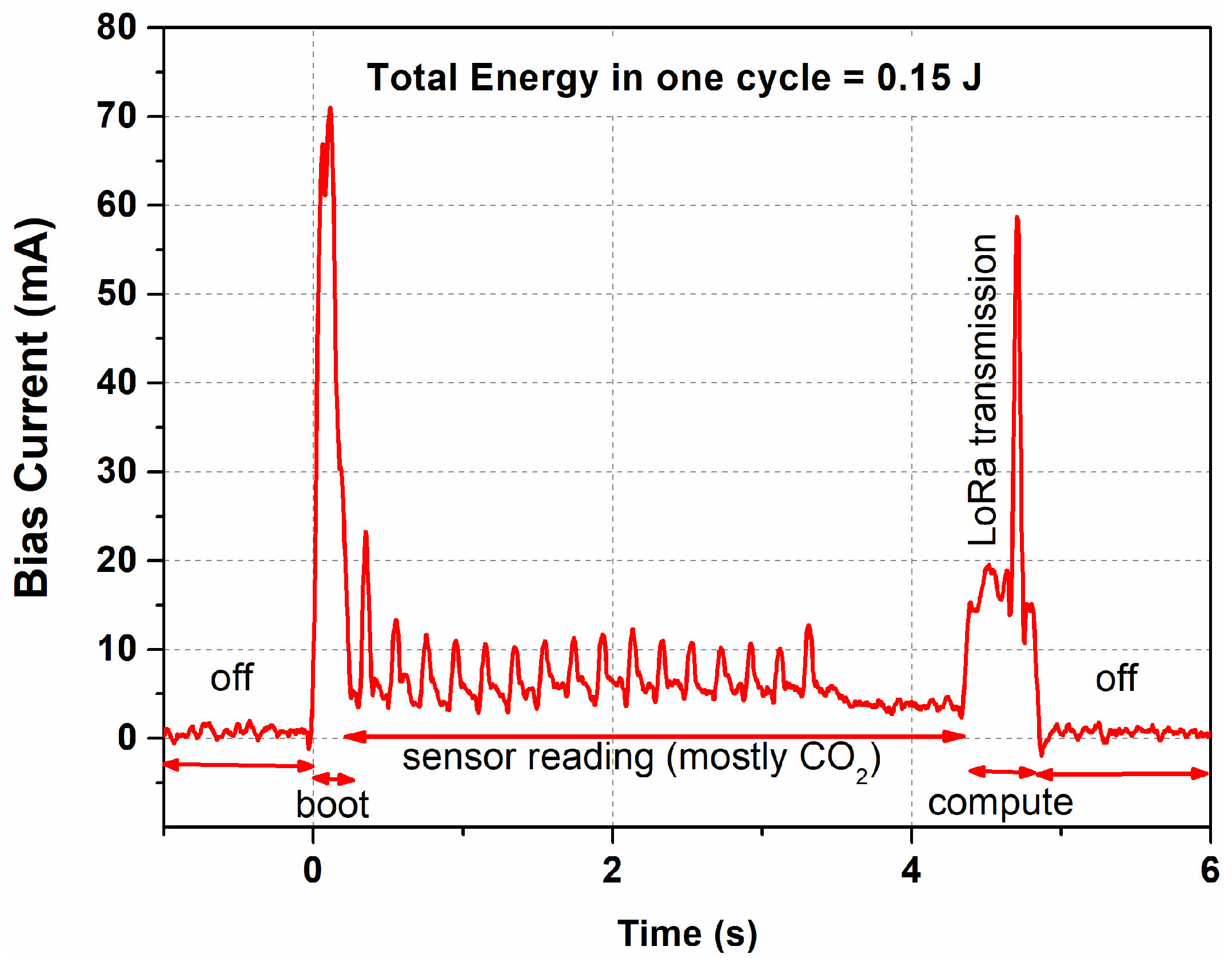
In Figure 5, the time evolution of the total bias current during the second wake up part is shown, which is the most energy consuming one. It is possible to separate different zones, evidenced by the double arrows in the figure. The “off” corresponds to the board switched off with an overall current consumption of less than 1 μA. The “boot” is the boot sequence of the SoC with a duration of about 150 ms and a large current consumption. The “sensor reading” phase has a duration of about 4 s (determined by the CoZir Blink sensor), during which the SoC is in sleep mode and consumes a few mA. At the end of this time, there is a “compute” phase where the other sensors are read, as well as the SC and battery voltages. Additionally, in this phase, all the data are prepared and sent to the transceiver chip, which transmits them to the gateway. The transmission time is visible as a pronounced peak in the current consumption, with a duration of less than 100 ms. The output power is set to the minimum value (−9 dBm) which, in our case, allows for a transmission range of about 10 m in open air. The chip can provide up to 31 dB more power, thus allowing, in principle and if needed, it to easily reach much longer distances at the expense of larger power consumption. Given the reported transmission time, the difference between minimum power and maximum transmission power accounts for about 27 mJ, a small increase in the average energy consumption per measurement cycle.
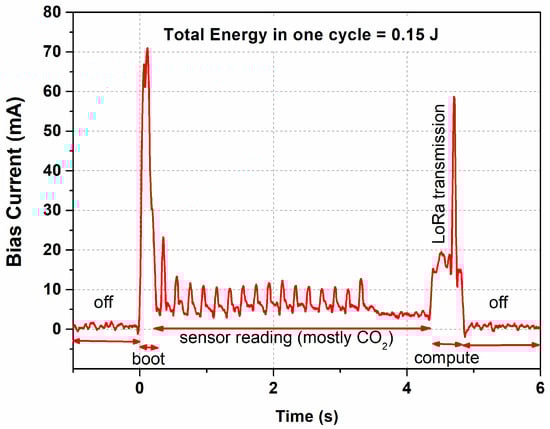
Figure 5.
Current consumption during one measurement cycle.
After all the discussed phases, the timer chip is programmed for the next wake up and the board is powered off, bringing the current consumption to a negligible value.
By considering the overall current consumption profile, it is possible to estimate the energy cost of one periodic measurement, leading to 0.15 J. In order to evaluate if such a cost is sustainable by the system, it is necessary to consider the expected overall daily energy flow.
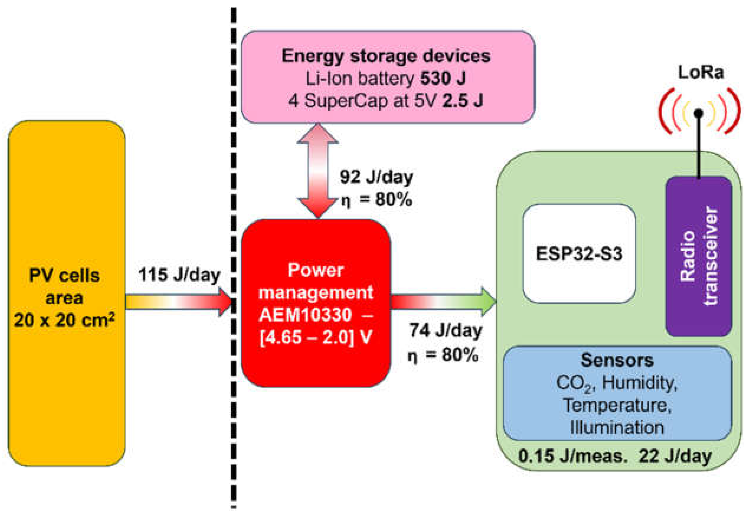
The energy flow shown in Figure 6 allows us to make an evaluation of energy generation and consumption, giving information on the reliability of the electronic test board discussed here as a solution for sustainable indoor monitoring applications. As evident from the dashed vertical line in Figure 6, it is necessary to separate the energy source part, that is, the input energy (left side), from the part of power management, sensors measure, and data transmission, that is, the energy output (right side).

Figure 6.
Energy flow expected in a typical indoor energy harvesting application.
By considering perovskite solar cells (400 cm2 of area), optimized for indoor illumination (10 μW/cm2 power density at 200 lux of illumination), working for 8 h/day, the energy produced by PV is ~92 J/day, with an 80% storage efficiency. The TEG part, instead, is less efficient (ηTEG = 40%), providing only ~1 J/day of generated energy. Overall, the harvesting stage generates ~93 J/day, when standard values are considered for the indoor illumination level (usually, ranging from 100 to 300 lux in living rooms) and for room temperature (usually, around 20 °C). The energy stored is then made available at the load port, with a voltage of 3.3 V for the board to operate. The conversion from load to output also shows about 80% efficiency, thus bringing the overall daily available energy to about 74 J.
Moving on to the energy consumption part, from the discussion above each measurement cycle consumes 0.15 J. Assuming a cycle duration of 10 min, there are 144 cycles in one day, leading to an overall energy consumption of about 22 J.
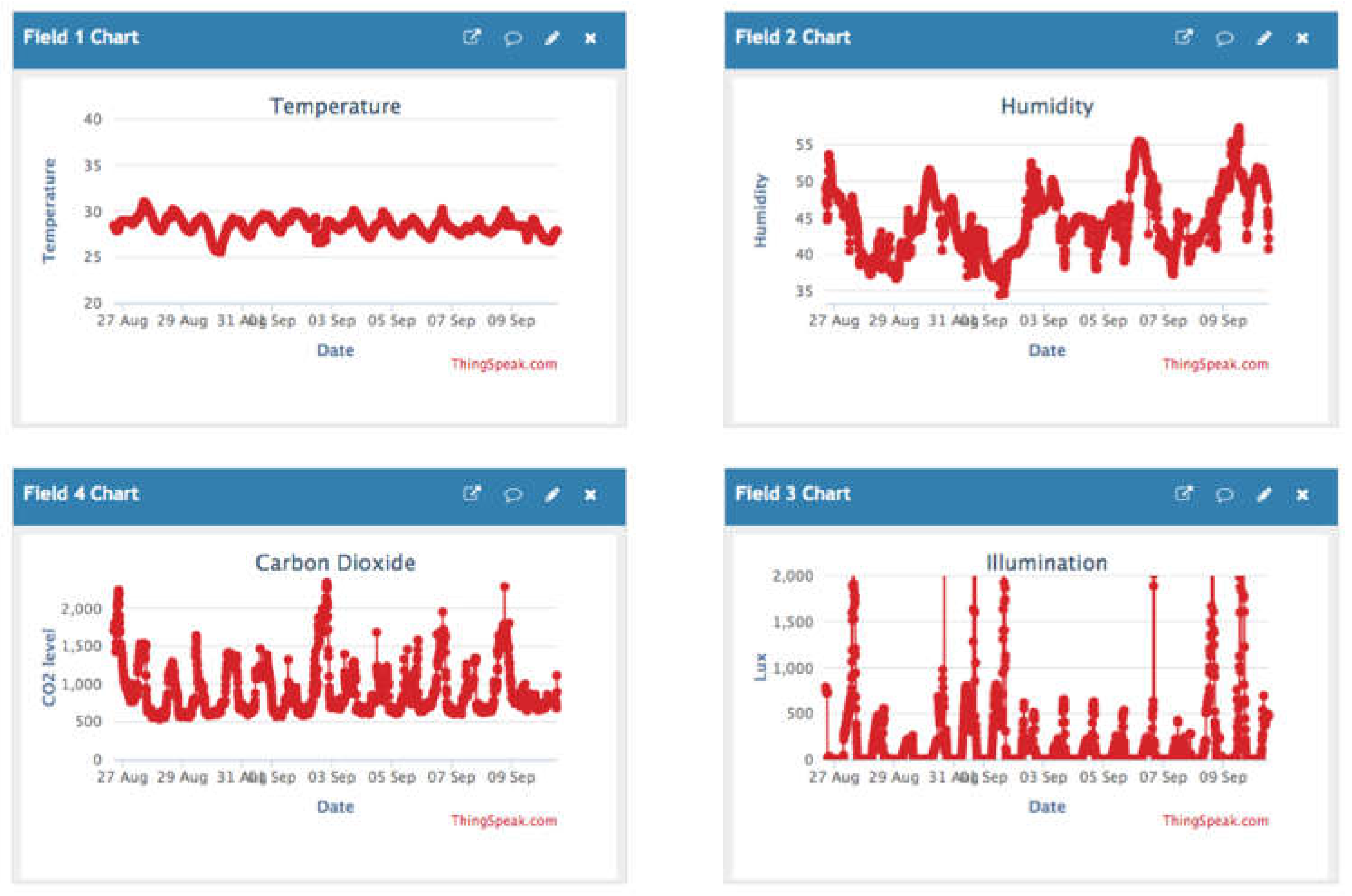
The evaluation of energy generation and consumption provides a positive balance of ~52 J/day. Such an excess is used to recharge the storage devices, which have been identified in four eco-friendly SCs at 5 V (~2.5 J of energy available) and in a Li-ion polymer battery at 3.7 V (~530 J of energy available). In this way, the electronic test board can operate over the long term continuously and reliably, and also during the night or during longer periods without indoor illumination (e.g., weekends). In Figure 7, an example time series of the sensor data for a duration of 14 days is shown. The data were acquired and transferred by the LoRa transceiver to a Wi-Fi gateway, and from here to a free data repository [47].
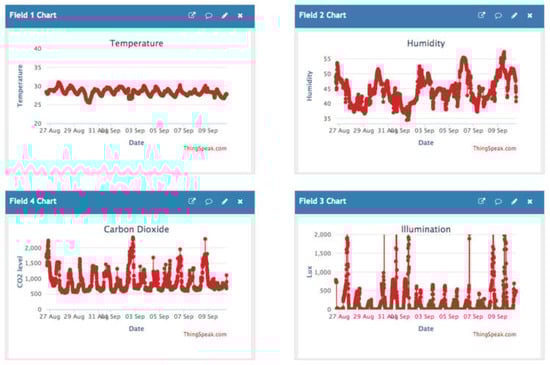
Figure 7.
Screenshot of the temporal series of sensor measurements, recorded over a period of 14 days and stored on the data repository of thingspeak.com.
4. Conclusions
The developed system for indoor monitoring inside buildings presents a versatile platform for testing and prototyping a variety of sensor configurations while accommodating a range of power sources, including both traditional and eco-sustainable options. This flexibility enables researchers and engineers to explore new possibilities in fields such as environmental monitoring and energy harvesting. The evaluation of energy generation and consumption revealed an excess of 52 J/day, ensuring that the platform can operate continuously and reliably. This makes it a robust and viable solution for sustainable indoor monitoring applications. The integration of eco-friendly components, such as sensors and a supercapacitor, further enhances the environmental profile of the system, reinforcing its suitability for applications that prioritize sustainability. Overall, the results highlight the potential of this platform to contribute to environmentally conscious monitoring solutions, paving the way for broader adoption in various indoor settings.
Looking forward, further optimization is crucial to improving the energy efficiency and sustainability of the platform. Future system enhancements could include more sustainable photovoltaic modules with stable long-term performance, ensuring reliable energy harvesting from the environment over extended periods. Additionally, increasing the storage capacity of eco-friendly supercapacitors, combined with reducing the energy consumption of the platform, could eliminate the need for a Li-ion battery, enabling a battery-less configuration.
Expanding the use of low-power, eco-sustainable sensors would further reduce the overall environmental impact of the platform. These advancements will enhance the ability of the platform to provide sustainable and efficient monitoring solutions in various indoor environments.
Author Contributions
Conceptualization, G.L. and G.A.; methodology, G.L., C.B. and S.P.; validation, C.B. and S.P.; resources, G.L.; data curation, G.A.; writing—original draft preparation, G.L., C.B. and S.P.; writing—review and editing, G.L., C.B. and S.P. All authors have read and agreed to the published version of the manuscript.
Funding
This research was funded in the Program Agreement between the Italian National Agency for New Technologies, Energy and Sustainable Economic Development (ENEA) and the Ministry of Environment and Energy Safety for Electric System Research, in the framework of its Implementation Plan for 2022–2024. In particular, the activity is included in Project 1.5 “High-efficiency buildings for the energy transition”, Work Package 3 “Innovative technologies and components for increasing the energy performance of buildings”. C. Barone and S. Pagano gratefully acknowledge the financial support from the University of Salerno through Projects nr. FRB20BARON, FRB21CAVAL, FRB22PAGAN, and FRB23BARON.
Data Availability Statement
The data presented in this study are available on request from the corresponding author.
Acknowledgments
The authors would like to thank S. Abate of CNR-SPIN Salerno (Italy) for his technical support.
Conflicts of Interest
The authors declare no conflict of interest.
References
- International Renewable Energy Agency (IRENA). World Energy Transitions Outlook 2022: 1.5 °C Pathway; IRENA: Abu Dhabi, United Arab Emirates, 2022. [Google Scholar]
- United Nations Environment Programme (UNEP). Global Status Report for Buildings and Construction: Beyond Foundations: Mainstreaming Sustainable Solutions to Cut Emissions from the Buildings Sector; UNEP: Nairobi, Kenya, 2024. [Google Scholar]
- Scherz, M.; Rossegger, C.; Kreiner, H.; Passer, A. Monitoring and Reporting of Buildings’ Greenhouse Gas Emissions: Implementation in the Austrian Building Submission Procedure. IOP Conf. Ser. Earth Environ. Sci. 2024, 1363, 12020. [Google Scholar] [CrossRef]
- Scrucca, F.; Ingrao, C.; Barberio, G.; Matarazzo, A.; Lagioia, G. On the Role of Sustainable Buildings in Achieving the 2030 UN Sustainable Development Goals. Environ. Impact Assess. Rev. 2023, 100, 107069. [Google Scholar] [CrossRef]
- Özer, E.; Imamovic, I.; Kranz, L.; Azzolini, G.; Di Turi, S.; Hugony, F.; Zanghirella, F. National Building Renovation Plans and Zero-Emission Buildings: Policy Needs and Best Practices; Buildings Performance Institute Europe: Berlin, Germany, 2024. [Google Scholar]
- International Energy Agency (IEA). Net Zero by 2050 A Roadmap for the Global Energy Sector; IEA: Paris, France, 2021. [Google Scholar]
- Pecunia, V.; Occhipinti, L.G.; Hoye, R.L.Z. Emerging Indoor Photovoltaic Technologies for Sustainable Internet of Things. Adv. Energy Mater. 2021, 11, 2100698. [Google Scholar] [CrossRef]
- Jo, J.; Jo, B.; Kim, J.; Kim, S.; Han, W. Development of an IoT-Based Indoor Air Quality Monitoring Platform. J. Sens. 2020, 2020, 8749764. [Google Scholar] [CrossRef]
- Xu, C.; Song, Y.; Han, M.; Zhang, H. Portable and Wearable Self-Powered Systems Based on Emerging Energy Harvesting Technology. Microsyst. Nanoeng. 2021, 7, 8749764. [Google Scholar] [CrossRef]
- Ali, A.; Shaukat, H.; Bibi, S.; Altabey, W.A.; Noori, M.; Kouritem, S.A. Recent Progress in Energy Harvesting Systems for Wearable Technology. Energy Strateg. Rev. 2023, 49, 101124. [Google Scholar] [CrossRef]
- Yue, X.; Kauer, M.; Bellanger, M.; Beard, O.; Brownlow, M.; Gibson, D.; Clark, C.; MacGregor, C.; Song, S. Development of an Indoor Photovoltaic Energy Harvesting Module for Autonomous Sensors in Building Air Quality Applications. IEEE Internet Things J. 2017, 4, 2092–2103. [Google Scholar] [CrossRef]
- Prauzek, M.; Konecny, J.; Borova, M.; Janosova, K.; Hlavica, J.; Musilek, P. Energy Harvesting Sources, Storage Devices and System Topologies for Environmental Wireless Sensor Networks: A Review. Sensors 2018, 18, 2446. [Google Scholar] [CrossRef]
- Kanoun, O.; Bradai, S.; Khriji, S.; Bouattour, G.; El Houssaini, D.; Ben Ammar, M.; Naifar, S.; Bouhamed, A.; Derbel, F.; Viehweger, C. Energy-Aware System Design for Autonomous Wireless Sensor Nodes: A Comprehensive Review. Sensors 2021, 21, 548. [Google Scholar] [CrossRef]
- Priya, S.; Song, H.-C.; Zhou, Y.; Varghese, R.; Chopra, A.; Kim, S.-G.; Kanno, I.; Wu, L.; Ha, D.S.; Ryu, J.; et al. A Review on Piezoelectric Energy Harvesting: Materials, Methods, and Circuits. Energy Harvest. Syst. 2017, 4, 3–39. [Google Scholar] [CrossRef]
- Wen, Z.; Yang, Y.; Sun, N.; Li, G.; Liu, Y.; Chen, C.; Shi, J.; Xie, L.; Jiang, H.; Bao, D.; et al. A Wrinkled PEDOT:PSS Film Based Stretchable and Transparent Triboelectric Nanogenerator for Wearable Energy Harvesters and Active Motion Sensors. Adv. Funct. Mater. 2018, 28, 1803684. [Google Scholar] [CrossRef]
- Vullers, R.J.M.; van Schaijk, R.; Doms, I.; Van Hoof, C.; Mertens, R. Micropower Energy Harvesting. Solid. State. Electron. 2009, 53, 684–693. [Google Scholar] [CrossRef]
- Mathews, I.; Kantareddy, S.N.; Buonassisi, T.; Peters, I.M. Technology and Market Perspective for Indoor Photovoltaic Cells. Joule 2019, 3, 1415–1426. [Google Scholar] [CrossRef]
- Pirc, M.; Ajdič, Ž.; Uršič, D.; Jošt, M.; Topič, M. Indoor Energy Harvesting With Perovskite Solar Cells for IoT Applications─A Full Year Monitoring Study. ACS Appl. Energy Mater. 2024, 7, 565–575. [Google Scholar] [CrossRef]
- Müller, D.; Jiang, E.; Rivas-Lazaro, P.; Baretzky, C.; Loukeris, G.; Bogati, S.; Paetel, S.; Irvine, S.J.C.; Oklobia, O.; Jones, S.; et al. Indoor Photovoltaics for the Internet-of-Things–A Comparison of State-of-the-Art Devices from Different Photovoltaic Technologies. ACS Appl. Energy Mater. 2023, 6, 10404–10414. [Google Scholar] [CrossRef]
- Elvidge, C.D.; Keith, D.M.; Tuttle, B.T.; Baugh, K.E. Spectral Identification of Lighting Type and Character. Sensors 2010, 10, 3961–3988. [Google Scholar] [CrossRef]
- Chakraborty, A.; Lucarelli, G.; Xu, J.; Skafi, Z.; Castro-Hermosa, S.; Kaveramma, A.B.; Balakrishna, R.G.; Brown, T.M. Photovoltaics for Indoor Energy Harvesting. Nano Energy 2024, 128, 109932. [Google Scholar] [CrossRef]
- Philipps, S. Photovoltaics Report; Fraunhofer ISE: Freiburg im Breisgau, Germany, 2024. [Google Scholar]
- Barone, C.; Pagano, S. What Can Electric Noise Spectroscopy Tell Us on the Physics of Perovskites? Coatings 2021, 11, 96. [Google Scholar] [CrossRef]
- Landi, G.; Neitzert, H.C.; Barone, C.; Mauro, C.; Lang, F.; Albrecht, S.; Rech, B.; Pagano, S. Correlation between Electronic Defect States Distribution and Device Performance of Perovskite Solar Cells. Adv. Sci. 2017, 4, 1700183. [Google Scholar] [CrossRef]
- Kojima, A.; Teshima, K.; Shirai, Y.; Miyasaka, T. Organometal Halide Perovskites as Visible-Light Sensitizers for Photovoltaic Cells. J. Am. Chem. Soc. 2009, 131, 6050–6051. [Google Scholar] [CrossRef]
- Landi, G.; Pagano, S.; Neitzert, H.C.; Mauro, C.; Barone, C. Noise Spectroscopy: A Tool to Understand the Physics of Solar Cells. Energies 2023, 16, 1296. [Google Scholar] [CrossRef]
- Jeong, M.; Choi, I.W.; Go, E.M.; Cho, Y.; Kim, M.; Lee, B.; Jeong, S.; Jo, Y.; Choi, H.W.; Lee, J.; et al. Stable Perovskite Solar Cells with Efficiency Exceeding 24.8% and 0.3-V Voltage Loss. Science 2020, 369, 1615–1620. [Google Scholar] [CrossRef] [PubMed]
- Olabi, A.G.; Al-Murisi, M.; Maghrabie, H.M.; Yousef, B.A.A.; Sayed, E.T.; Alami, A.H.; Abdelkareem, M.A. Potential Applications of Thermoelectric Generators (TEGs) in Various Waste Heat Recovery Systems. Int. J. Thermofluids 2022, 16, 100249. [Google Scholar] [CrossRef]
- Sonkusale, S.; Shojaei Baghini, M.; Aeron, S. Power Management Circuits for Energy Harvesting. In Flexible Bioelectronics with Power Autonomous Sensing and Data Analytics; Sonkusale, S., Shojaei Baghini, M., Aeron, S., Eds.; Springer International Publishing: Cham, Switzerland, 2022; pp. 121–142. ISBN 978-3-030-98538-7. [Google Scholar]
- Calautit, K.; Nasir, D.S.N.M.; Hughes, B.R. Low Power Energy Harvesting Systems: State of the Art and Future Challenges. Renew. Sustain. Energy Rev. 2021, 147, 111230. [Google Scholar] [CrossRef]
- Kim, S.; Vyas, R.; Bito, J.; Niotaki, K.; Collado, A.; Georgiadis, A.; Tentzeris, M.M. Ambient RF Energy-Harvesting Technologies for Self-Sustainable Standalone Wireless Sensor Platforms. Proc. IEEE 2014, 102, 1649–1666. [Google Scholar] [CrossRef]
- Conway, B.E. Transition from “Supercapacitor” to “Battery” Behavior in Electrochemical Energy Storage. J. Electrochem. Soc. 1991, 138, 1539. [Google Scholar] [CrossRef]
- Noori, A.; El-Kady, M.F.; Rahmanifar, M.S.; Kaner, R.B.; Mousavi, M.F. Towards Establishing Standard Performance Metrics for Batteries, Supercapacitors and Beyond. Chem. Soc. Rev. 2019, 48, 1272–1341. [Google Scholar] [CrossRef]
- Simon, P.; Gogotsi, Y. Perspectives for Electrochemical Capacitors and Related Devices. Nat. Mater. 2020, 19, 1151–1163. [Google Scholar] [CrossRef]
- Amici, J.; Asinari, P.; Ayerbe, E.; Barboux, P.; Bayle-Guillemaud, P.; Behm, R.J.; Berecibar, M.; Berg, E.; Bhowmik, A.; Bodoardo, S.; et al. A Roadmap for Transforming Research to Invent the Batteries of the Future Designed within the European Large Scale Research Initiative BATTERY 2030+. Adv. Energy Mater. 2022, 12, 2102785. [Google Scholar] [CrossRef]
- Keshavarzi, A.; Hoek, W. van den Edge Intelligence—On the Challenging Road to a Trillion Smart Connected IoT Devices. IEEE Des. Test 2019, 36, 41–64. [Google Scholar] [CrossRef]
- Peters, J.F.; Baumann, M.; Zimmermann, B.; Braun, J.; Weil, M. The Environmental Impact of Li-Ion Batteries and the Role of Key Parameters—A Review. Renew. Sustain. Energy Rev. 2017, 67, 491–506. [Google Scholar] [CrossRef]
- Dühnen, S.; Betz, J.; Kolek, M.; Schmuch, R.; Winter, M.; Placke, T. Toward Green Battery Cells: Perspective on Materials and Technologies. Small Methods 2020, 4, 2000039. [Google Scholar] [CrossRef]
- Landi, G.; La Notte, L.; Palma, A.L.; Sorrentino, A.; Maglione, M.G.; Puglisi, G. A Comparative Evaluation of Sustainable Binders for Environmentally Friendly Carbon-Based Supercapacitors. Nanomaterials 2022, 12, 46. [Google Scholar] [CrossRef] [PubMed]
- Landi, G.; La Notte, L.; Granata, V.; Avallone, G.; Barone, C.; Carapella, G.; Pagano, S.; Palma, A.L.; Sdringola, P.; Puglisi, G. Impact of Acetate-Based Hydrogel Electrolyte on Electrical Performance and Stability of Eco-Friendly Supercapacitors. ChemElectroChem 2023, 10, e202300443. [Google Scholar] [CrossRef]
- Landi, G.; La Notte, L.; Palma, A.L.; Puglisi, G. Electrochemical Performance of Biopolymer-Based Hydrogel Electrolyte for Supercapacitors with Eco-Friendly Binders. Polymers 2022, 14, 4445. [Google Scholar] [CrossRef]
- Pal, B.; Yang, S.; Ramesh, S.; Thangadurai, V.; Jose, R. Electrolyte Selection for Supercapacitive Devices: A Critical Review. Nanoscale Adv. 2019, 1, 3807–3835. [Google Scholar] [CrossRef]
- Raje, K. Microcontrollers Market Report 2024; Cognitive Market Research: Chicago, IL, USA, 2024. [Google Scholar]
- Landi, G.; Granata, V.; Germano, R.; Pagano, S.; Barone, C. Low-Power and Eco-Friendly Temperature Sensor Based on Gelatin Nanocomposite. Nanomaterials 2022, 12, 2227. [Google Scholar] [CrossRef]
- Landi, G.; Pagano, S.; Granata, V.; Avallone, G.; La Notte, L.; Palma, A.L.; Sdringola, P.; Puglisi, G.; Barone, C. Regeneration and Long-Term Stability of a Low-Power Eco-Friendly Temperature Sensor Based on a Hydrogel Nanocomposite. Nanomaterials 2024, 14, 283. [Google Scholar] [CrossRef]
- Zhivov, A.; Rose, W.; Patenaude, R.; Williams, W.J. Requirements for Building Thermal Conditions under Normal and Emergency Operations in Extreme Climates. ASHRAE J. 2021, 127, 693–704. [Google Scholar]
- ThingSpeak. The IoT Platform with MATLAB Analytics. Available online: https://thingspeak.com (accessed on 1 September 2024).
Disclaimer/Publisher’s Note: The statements, opinions and data contained in all publications are solely those of the individual author(s) and contributor(s) and not of MDPI and/or the editor(s). MDPI and/or the editor(s) disclaim responsibility for any injury to people or property resulting from any ideas, methods, instructions or products referred to in the content. |
© 2024 by the authors. Licensee MDPI, Basel, Switzerland. This article is an open access article distributed under the terms and conditions of the Creative Commons Attribution (CC BY) license (https://creativecommons.org/licenses/by/4.0/).