Article

An Improved Prevention Strategy Based on Fault Probability Detection for Commutation Failure in Line-Commutated Converter-Based High-Voltage Direct Current Transmission Systems

1
State Grid Economic and Technological Research Institute Co., Ltd., Beijing 102211, China
2
College of Electrical Engineering, Sichuan University, Chengdu 610065, China
3
State Grid Sichuan Electric Power Research Institute, Chengdu 610041, China
*
Author to whom correspondence should be addressed.
Electronics 2024, 13(19), 3804; https://doi.org/10.3390/electronics13193804
Submission received: 1 August 2024 / Revised: 20 September 2024 / Accepted: 20 September 2024 / Published: 25 September 2024
(This article belongs to the Special Issue Control of Power Quality and System Stability)

Abstract

:
Commutation failure (CF) is one of the most prevalent events in line-commutated converter-based high-voltage direct current (LCC–HVDC) systems. The frequent occurrence of CF poses a significant threat to the safe and stable operation of power grids. The commutation failure prevention control (CFPREV) is the main method to prevent the initial CF, which relies on the detection of a drop in AC voltage. However, its slow fault detection hinders the rapid response of post-fault control, thereby affecting the effectiveness of CF suppression. Therefore, this paper proposes a fast fault detection method based on Bayesian theory. This algorithm can calculate the conditional probability of each variable in a given dataset, effectively mitigating the impact of noise and errors in data to yield precise and dependable results. By processing the collected continuous data and calculating the probability of the existence of a fault point, it determines whether a fault occurs. Based on this method, an improved prevention strategy is proposed, which can effectively enhance the CF resilience of LCC–HVDC systems under AC faults. Finally, using the power systems computer-aided design (PSCAD) platform, the accuracy of the fault probability detection algorithm was verified based on actual engineering data. The effectiveness of the proposed strategy was further validated under three typical fault scenarios, leading to significant improvements: a 64.12% reduction in detection time for three-phase grounding faults, a 69.88% decrease for single line-to-ground faults, and a 36.84% improvement in phase-to-phase fault detection. Additionally, the overall performance of the strategy was thoroughly assessed through extensive simulations covering various fault cases within a selected range of typical faults. The simulations demonstrated the superiority of the proposed strategy in CF mitigation, with a significant reduction in incidents from 89 to 34 out of 150 tested scenarios. This highlights the robustness and reliability of the proposed strategy.

1. Introduction

Due to the advantages of low power losses of thyristors and bulk power transmission capacity, line-commutated converter-based high-voltage direct current (LCC–HVDC) systems have played an important role in long-distance bulk power transmission and asynchronous interconnections [1,2,3]. However, commutation failure (CF) is an adverse and frequent event at the inverter side of LCC–HVDC, often caused by AC faults at the receiving end of the LCC–HVDC [4]. The occurrence of CF can cause a short-term surge in DC current, resulting in the overheating of converter valves and subsequently shortening their lifespan. In addition, CF can also lead to temporary imbalances in power transfer, and even trigger HVDC system blocking and other severe cascading failures [5]. These pose significant challenges to the safe and stable operation of power grids. Therefore, it is necessary to implement appropriate measures to prevent the occurrence of CF for the safe operation of the power grid [6].
To prevent CF occurrence, three primary methods have been investigated in previous studies: adding auxiliary equipment [7,8,9], modifying the converter topology [10,11], and optimizing the control strategy [12,13]. Given the high costs associated with adding converter equipment and modifying the converter topology, as well as the limitations in voltage level and transmission capacity, the optimized control strategy is generally preferred for suppressing CF.
Commutation failure prevention (CFPREV) control is widely adopted in engineering projects to suppress the initial CF at fault inception [14]. In [15], the mechanism of CFPREV is reported for the first time. The central idea revolves around compensating the firing angle to increase the commutation margin by promptly detecting any AC fault. Therefore, a swift and precise judgment of the AC fault is crucial to ensure the timely implementation of CFPREV. Many researchers have focused on improving fault detection methods in traditional CFPREV control. For instance, the authors of [16] proposed a sin–cos method for real-time grid status monitoring, addressing the CFPREV’s limitation of slow initiation when the AC voltage crosses zero. However, the response speed of this method remains unsatisfactory due to the delay in the measurement unit. In [17,18], reducing the CFPREV threshold and optimizing control parameters enhance the CF resistance of the converter. However, threshold and parameter adjustments are heavily dependent on engineering experience, lack theoretical analysis, and there is a risk of frequent start-ups. In [19], the virtual phase-locked voltage is constructed, and the difference between the virtual phase-locked voltage and the actual commutation voltage is used as the criterion for policy start-up, which improves the speed of fault detection. The authors of [20,21,22] proposed various improvements to the PLL structure to solve the problems of low PLL precision and poor dynamic response, which effectively improved the PLL phase-locking performance and anti-interference ability. However, the introduction of the new PLL caused changes to the system control structure, and its small-signal stability needed to be further verified. In addition, there are other works considering the influence of dynamic changes in AC voltage and DC current in the transient process [23,24], which effectively improve the control characteristics of the system, and its effectiveness needs to be verified by further engineering.
However, a common issue persists in the existing literature: the failure criterion often relies solely on comparing individual data points with a threshold value. In scenarios wherein the AC voltage dips are moderate, the fault information can easily be obscured by noise. Consequently, the control system fails to respond promptly and is thus unable to effectively prevent the occurrence of CF. To address this problem, it is necessary to investigate a fault detection method that can fulfill the need for rapid activation during faults, thereby mitigating the occurrence of CF. At present, several researchers have proposed various HVDC fault identification methods based on artificial intelligence algorithms, such as discrete wavelet transform (DWT) [25], Bayesian optimization [26,27], and artificial neural networks (ANNs) [28], which provide a new direction for HVDC fault identification research. However, the above methods have not been used in the study of commutation failure suppression.
In response to the aforementioned issues, this paper proposes an improved CF prevention strategy. This approach identifies AC faults by assessing the probability of the presence of fault points within a data sequence. By rapidly responding in the early stages of fault occurrence, the prevention of initial CF can be significantly enhanced. Furthermore, it addresses the challenge of slow activation of the traditional CFPREV under certain fault scenarios, thereby improving the sensitivity of the fault detection in control.
This paper presents its principal contributions as follows:
(1) An algorithm for detecting fault probabilities in the LCC–HVDC inverter is proposed. By transforming real-time voltage datasets into a fault probability distribution matrix, and defining a normalized expectation index, this approach offers a comprehensive evaluation of fault probabilities, considering multiple data points. Compared with traditional threshold-based fault detection algorithms, the proposed algorithm can effectively distinguish between fault occurrence instants and normal signal fluctuations, thereby significantly enhancing the speed of fault detection.
(2) An improved commutation failure prevention strategy based on fault probability detection is proposed. This strategy employs fault probability as a criterion index, triggering the firing angle in advance based on the real-time three-phase voltage sag magnitudes upon swift fault detection. This strategy is integrated with the controls in the LCC–HVDC inverter to rapidly enhance the commutation margin following a fault occurrence.

2. Brief Description of the LCC–HVDC Control System and the Mechanism of CFPREV Control

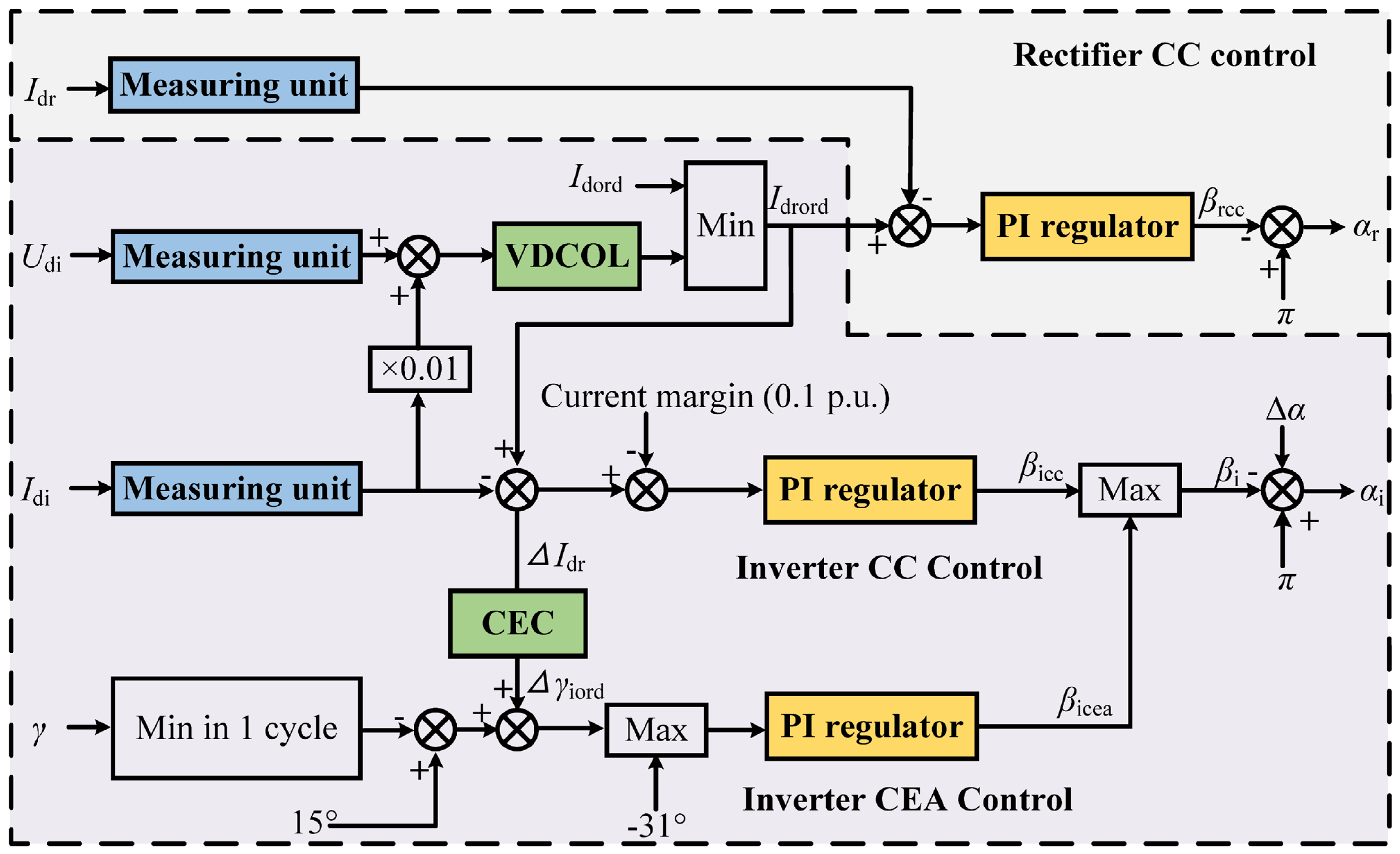
2.1. LCC–HVDC Control System
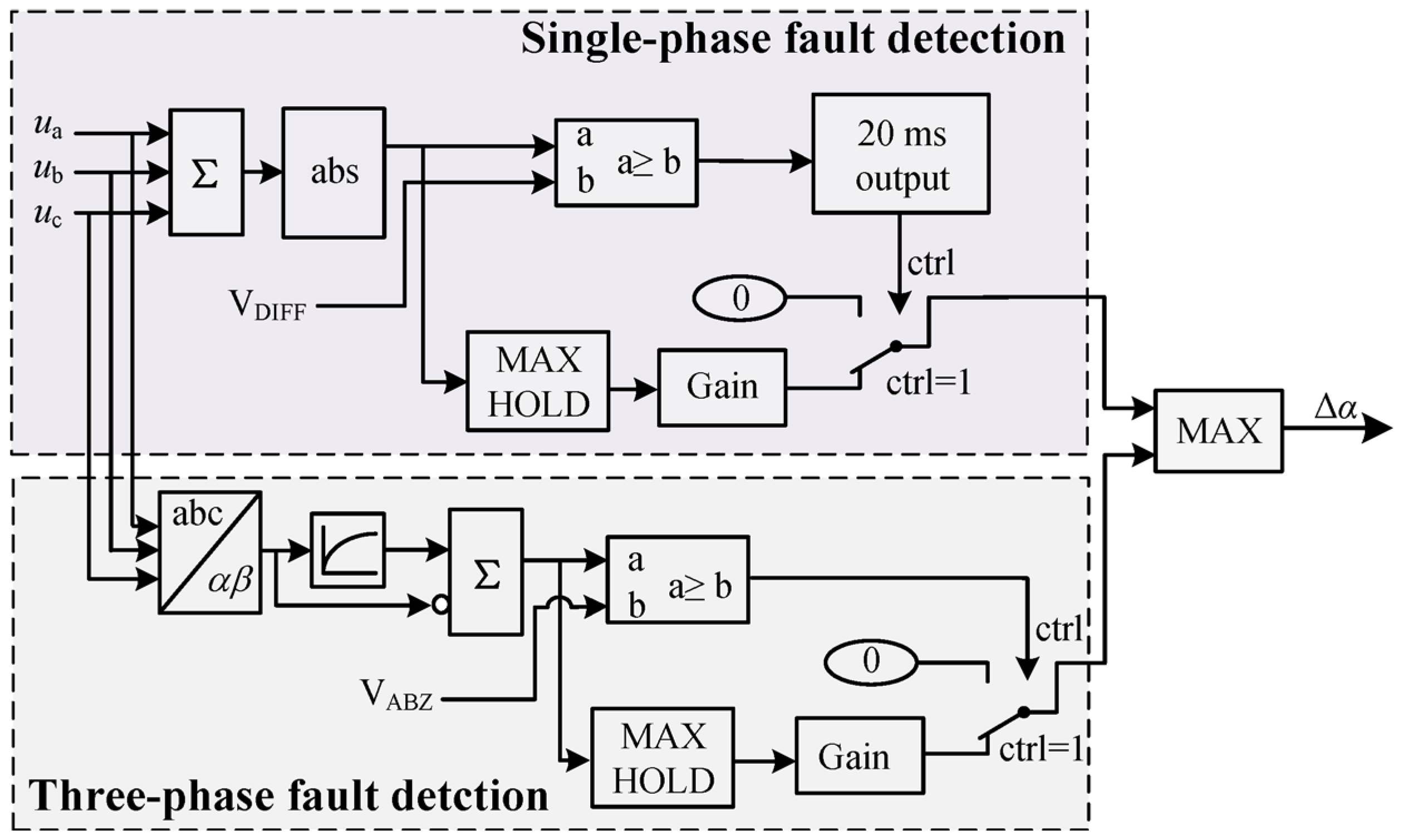
The studied LCC–HVDC system in this paper adopts the CIGRE Benchmark model [29], in which the rectifier configures with constant current (CC) control and constant firing angle control, and the inverter configures with CC control, constant extinction angle (CEA) control, current error control (CEC), and voltage-dependent current order limiter (VDCOL). When the system operates in the normal state, the rectifier adopts CC control and the inverter adopts CEA control. Figure 1 shows the schematic diagram of the fundamental control. The nomenclature of the related variables is provided in Table 1.

2.2. CFPREV Control

CFPREV control, which is configured in the inverter station of LCC–HVDC, plays an important role in mitigating the risk of CF caused by AC faults. The schematic diagram of CFPREV control is shown in Figure 2, where ua, ub, and uc are the instantaneous phase voltage of the AC system, VDIFF and VABZ are the threshold of the single-phase fault and three-phase fault detection, respectively, MAX HOLD means holding the maximin, and ∆α is the output firing angle from CFPREV. As can be seen in Figure 2, the CFPREV control includes two parts, a single-phase fault detection module and a three-phase fault detection module [30].
For the single-phase fault detection module, sum the collected ua, ub, and uc to obtain the zero-sequence voltage component u0. The expression of u0 is given as follows:
3 u 0 = u a + u b + u c
When u0 exceeds VDIFF, it is determined that a single-phase fault has occurred in the system. Otherwise, it is concluded that no such fault has occurred.
For three-phase fault detection, convert ua, ub, and uc to the rotation vector uαβ by Clark transformation. The expression of uαβ is given as follows:
u α u β = 2 3 1 1 2 1 2 0 3 2 3 2 u a u b u c
u α β = u α 2 + u β 2
where uα and uβ are the corresponding coordinate axis components of uαβ on the α and β axes of the αβ plane.
When uαβ exceeds VABZ, it is determined that a three-fault has occurred in the system. Otherwise, it is concluded that no such fault has occurred.
As soon as the system detects a fault, the CFPREV controller provides ∆α at the inverter to enlarge the commutation margin and mitigate the risk of CF. However, the threshold parameter of fault detection is deliberately set to a large value to prevent frequent activation of the controller caused by harmonics, noise, and other disturbances. Unfortunately, this may prevent the controller from initiating a rapid response after a fault occurs, thereby increasing the risk of CF. Therefore, it is necessary to improve the sensitivity of the CFPREV fault detection.

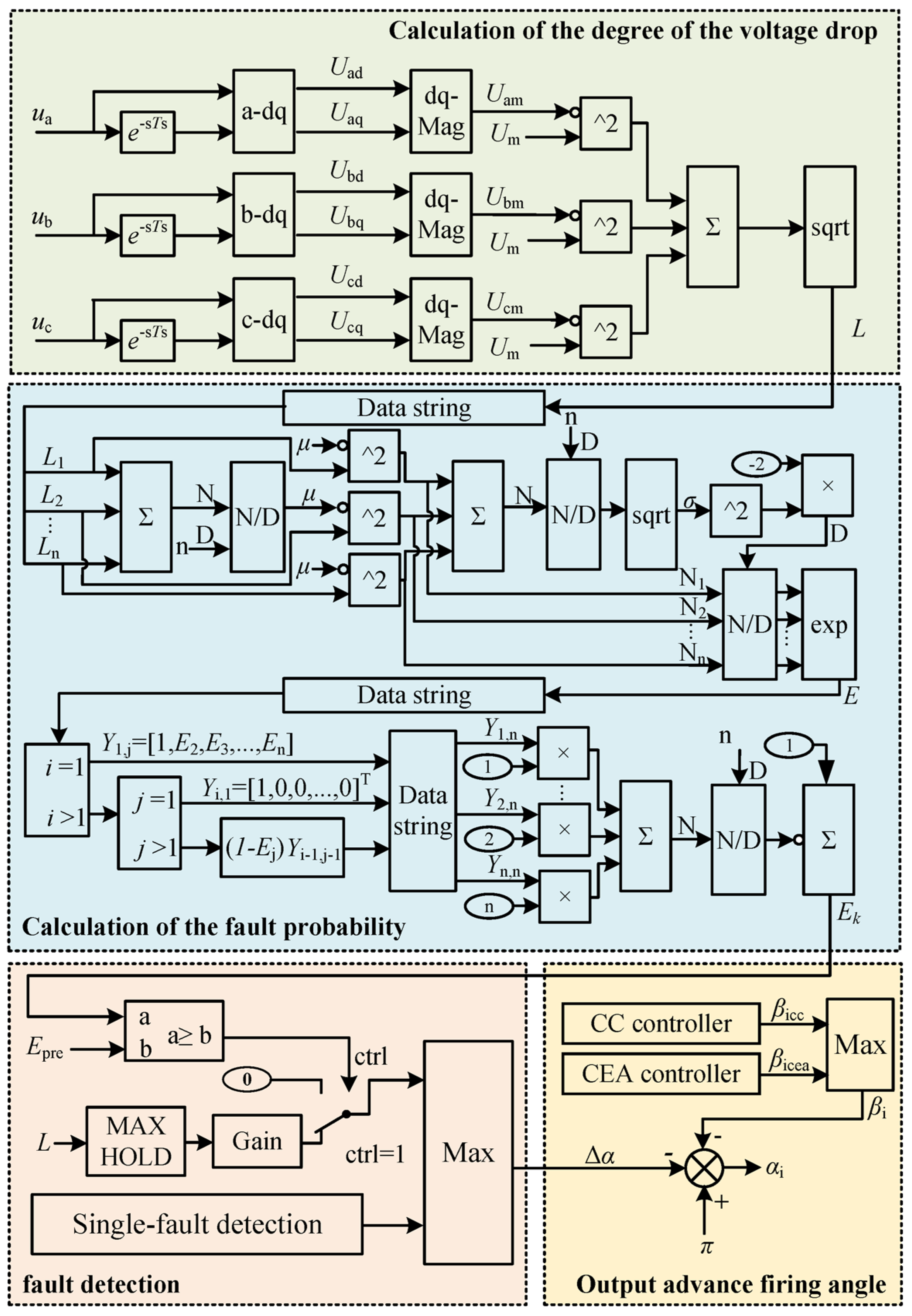
3. Improved Prevention Strategy Based on the Fault Probability Detection

3.1. Calculation of the Degree of Voltage Drop

Given that the uαβ criterion employed in CFPREV exhibits limited sensitivity in perceiving voltage dips during certain fault types such as two-phase faults, this can affect the control system’s ability to accurately assess the severity of the fault. Therefore, in this section, the voltage conversion method used in the three-phase fault detection of the CFPREV is modified from a Clark conversion to a Park conversion. Based on the Park conversion, the d and q axis component of each line voltage is calculated to access the degree of voltage drop.
Using Ts to denote the sampling period, the subscript k denotes the sampling result of phase x (x = a, b, c). Therefore, the phase voltage ux can be described as follows:
u x k = U x m cos k ω T s φ x
where Uxm is the voltage amplitude, and φx is the initial phase of the phase voltage.
To ease the process of analysis, define Uxd = Uxmcos(φx), Uxq = Uxmsin(φx). Based on this, the sampling results can be rewritten as follows:
u x k = U x d cos k ω T s + U x q sin k ω T s
Due to the sample period being small, the Uxd and Uxq obtained from continuous sampling results can be considered to be unchanged. Therefore, combining ux(k) and ux(k − 1) as well as Uxd and Uxq can be obtained as follows:
U x d ( k ) = sin ( k 1 ) ω T s u x ( k ) + sin k ω T s u x ( k 1 ) sin ω T s U x q ( k ) = cos ( k 1 ) ω T s u x ( k ) cos k ω T s u x ( k 1 ) sin ω T s
Furthermore, Uxm can be obtained as follows:
U x m = U x d 2 + U x q 2
When the system operates in the normal stage, the voltage amplitude of the three phases is Um. Subsequently, the degree of voltage drop in the collected voltage L can be estimated as follows:
L = U a m U m 2 + U b m U m 2 + U c m U m 2
The calculated value of L can be utilized to quantify the fault severity in the AC system, where a higher value of L indicates a more severe fault. Yet, the proposed L is still influenced by the degree of AC voltage drop, and it becomes challenging to accurately discern the occurrence of an AC fault when the drop is slight due to the low signal-to-noise ratio. Therefore, in Section 3.2, a prevention strategy based on the optimized L is proposed.

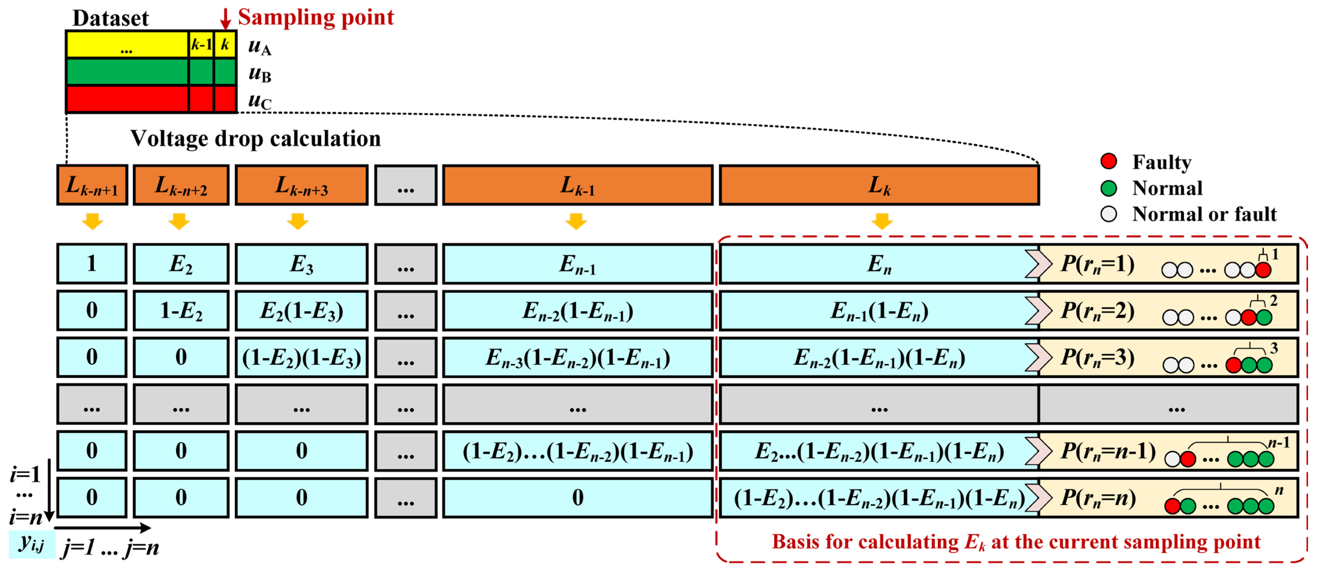
3.2. Fault Probability Detection Algorithm Based on Bayesian Theory

As mentioned in Section 3.1, the calculated value of L can indeed reflect the voltage amplitude drop. However, when the voltage drop is small, it becomes challenging to distinguish the fault value from the normal value using threshold segmentation. The primary reason for this is that threshold segmentation is typically applied to a single result. When the change in the result is small, it becomes difficult to determine whether the change is caused by a fault or noise. To address this challenge, a fault probability detection algorithm is investigated, which is based on Bayesian theory [31].
This paper does not simply classify each data point as normal or faulty. Instead, it assigns a multitude of possible states to each data point from a probabilistic perspective and integrates the probability information of a sequence of data points. This approach allows for significant fault characterization under real system fault conditions. A schematic diagram of the proposed algorithm is shown in Figure 3. First, the real-time updated three-phase voltage segments are converted into voltage sag segments using the algorithm described in Section 3.1, indicated by the orange region in the figure. Then, based on the data values, a fault probability matrix is constructed, represented by the blue region in the figure. For better understanding, the corresponding states of the matrix elements are shown in the yellow region. Finally, fault probability detection is performed by calculating the elements of the probability matrix.
Based on the AC voltage information under normal operating conditions, the mean value μ and standard deviation σ of L(k) are calculated:
μ = 1 N j = 1 N L ( j ) σ = 1 N j = 1 N ( L ( j ) μ ) 2
where N is the length of the dataset used for calculating μ and σ. These two parameters will be used as fixed parameters in the real-time fault probability detection algorithm.
During the system operation, a segment of continuous data is selected to form the dataset Lkn+1:k:
L k n + 1 : k = L k n + 1 , L k n + 2 , , L k
where n is the length of the selected dataset. Note that Lk corresponds to the latest sampled data, while Lkn+1:k−1 is related to the historical voltage data. Try to use the uniqueness of this dataset as the basis for fault diagnosis, and the used methods are described below.
First, assume that there is a state ri for each element L(kn + i). To define ri, there is the following premise:
(1) Variable j belongs to {1, 2, …, i}, making L(kn + j) faulty data;
(2) Any data between L(kn + j) and L(kn + i) are normal data;
(3) Assume the first data segment L(kn + 1) is faulty data.
Based on the above premises, ri can be calculated as follows:
r i = i j + 1
According to the definition of ri, use a recursion formula to calculate ri as follows:
r i = 1 L k n + i   is   faulty r i 1 + 1 L k n + i   is   normal
The physical meaning of the value of ri is the distance between the i-th element and the most recent faulty element. As illustrated in Figure 3, when rn = 3, it indicates that the n-th and (n − 1)-th elements are normal, while the (n − 2)-th element is faulty. Thus, the distance between the n-th element and the last faulty element is 2, giving rn = 3.
Due to the interference of noise or minor disturbance, it becomes difficult to discern whether a given data point is normal or faulty. Therefore, in this work, instead of categorizing each data point as either normal or faulty, a fault probability Ej is assigned to each data point. The probability Ej is calculated based on the corresponding data value L(kn + i) and the parameters μ and σ under normal conditions. The calculation formula for Ej is as follows:
E j = 1 e L k n + i μ 2 2 σ 2
Based on the definitions of ri and Ej above, a fault probability matrix Yi,j is constructed. In this matrix, each element yi,j represents the probability that the j-th data point in the dataset is at a distance i from the most recent faulty data point.
Based on (13) and (14), obtain any element yi,j by
y i . j = 1 i = 1 , j = 1 E j i = 1 , j 1 0 i 1 , j = 1 ( 1 E j ) y i 1 , j 1 i 1 , j 1
The blue region in Figure 3 visually illustrates the calculation of yi,j. It can be observed that, for a specific column, the larger the value of i, the more historical data are associated with the element. The n-th column (j = n) contains n data points, considering all possible fault states and calculating the probability for each state separately. To comprehensively assess the probability of fault occurrence in the entire dataset, a standardized fault distance expectation Ek is defined: As Ej increases, the standardized expectation Ek of rn decreases, and the converse is also true. As a result, Ek can be used to ascertain the presence of faulty data within the sequence Lkn+1:k. The expression for Ek is given as follows:
E k = 1 1 n i = 1 n i y i , n
Based on Figure 3 and Formula (15), it can be concluded that the fewer abnormal data points in the dataset, the smaller the value of Ek. When the system operates in the normal stage, the value of Ek is close to zero. Additionally, as the value of Ek increases, the probability of a fault also rises, with the maximum possible value being one.

3.3. The Improved Prevention Strategy Based on Fault Probability Detection

The proposed prevention strategy relies on the analysis in Section 3.2, which introduces a fault probability detection method. Given the diverse scenarios of AC system voltage reduction due to various AC system faults, it is imperative to propose a faster fault detection module. This enhancement not only augments the sensitivity of CFPREV and the control system but also helps mitigate the risk of CF. Figure 4 illustrates the schematic diagram of the improved prevention strategy.
As depicted in Figure 4, the single-phase fault detection control remains unchanged from the traditional CFPREV control, while the three-phase fault detection control has been modified. In the modified three-phase fault detection control, the instantaneous values of the phase voltages ua, ub, and uc serve as the input quantities. These values are then utilized in Equations (4) to (13) to assign a probability of failure to each data point. Subsequently, the probabilities of failure are comprehensively considered for all the data points within the data window, which are then fed into Equations (14) to (15). Using Bayesian theory, the probability Ek of the existence of faulty data within the window is calculated. Ek expresses the existence of faulty data within the window. If Ek exceeds the reference value Epre, a fault is concluded to have occurred in the system, and an advanced firing angle command is rapidly sent to the LCC–HVDC inverter.
The core of this strategy lies in the introduction of probabilistic thinking. Instead of solely focusing on whether the data at the current moment exceed a certain threshold, concentrate on the likelihood of a fault point’s existence across a series of data points. Most of the threshold-based criteria that rely solely on single-point judgments can be optimized, enhancing the stability of the criteria’s output using this strategy. Furthermore, it ensures a swift response from the control system under AC fault conditions, facilitating the rapid input of firing angle orders.

4. Simulation Validation

4.1. Validation of Fault Detection Based on Real Data

The essence of the strategy proposed in this paper is the rapid detection of faults. Firstly, the performance of the fault detection algorithm is validated based on a set of actual HVDC project fault data. In 2023, a CF event occurred in an HVDC system in China, caused by a phase-to-phase short-circuit of a 220 kV AC line near the inverter station. The traditional CFPREV control equipped in the HVDC system failed to detect the fault in time in this incident and started after the CF occurred. Based on the fault data of this event, the proposed normalized fault index Ek is calculated and compared with the voltage drop index ΔUαβ in the CFPREV control. Parameters μ and σ of the algorithm are set as 0.0257 and 0.28, respectively.
Figure 5 demonstrates the AC voltage at the receiving end, along with Ek and ΔUαβ. It can be seen that Ek rises rapidly after the fault, exceeding the threshold of 0.1 after 2.2 ms and reaching a maximum of 0.65, while ΔUαβ rises slowly and has a clear oscillation process. It exceeds the threshold after 12.8 ms. This indicates that the fault detection capability of the algorithm in this paper is superior to traditional algorithms, which can provide favorable conditions for rapid implementation to mitigate the occurrence of CF after faults.

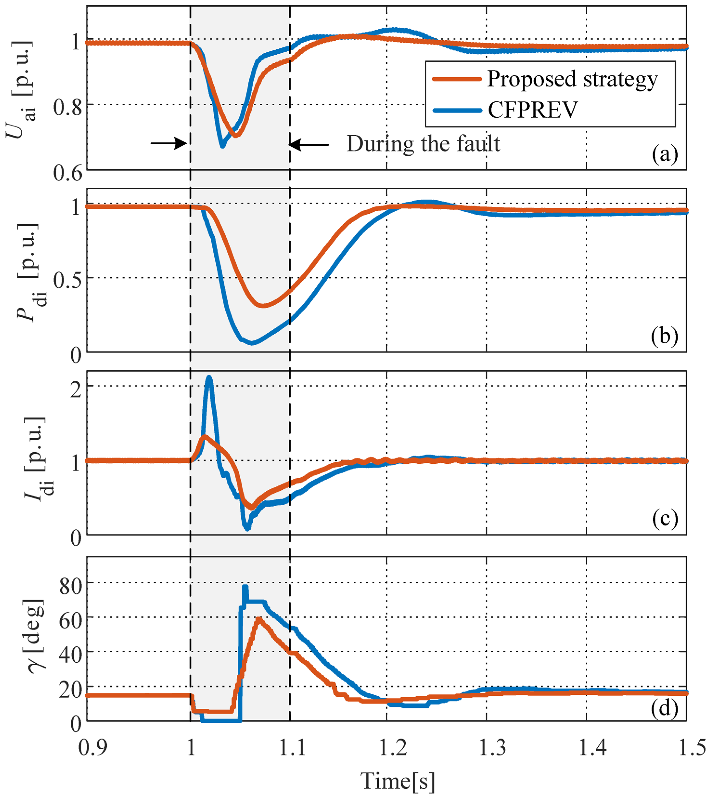
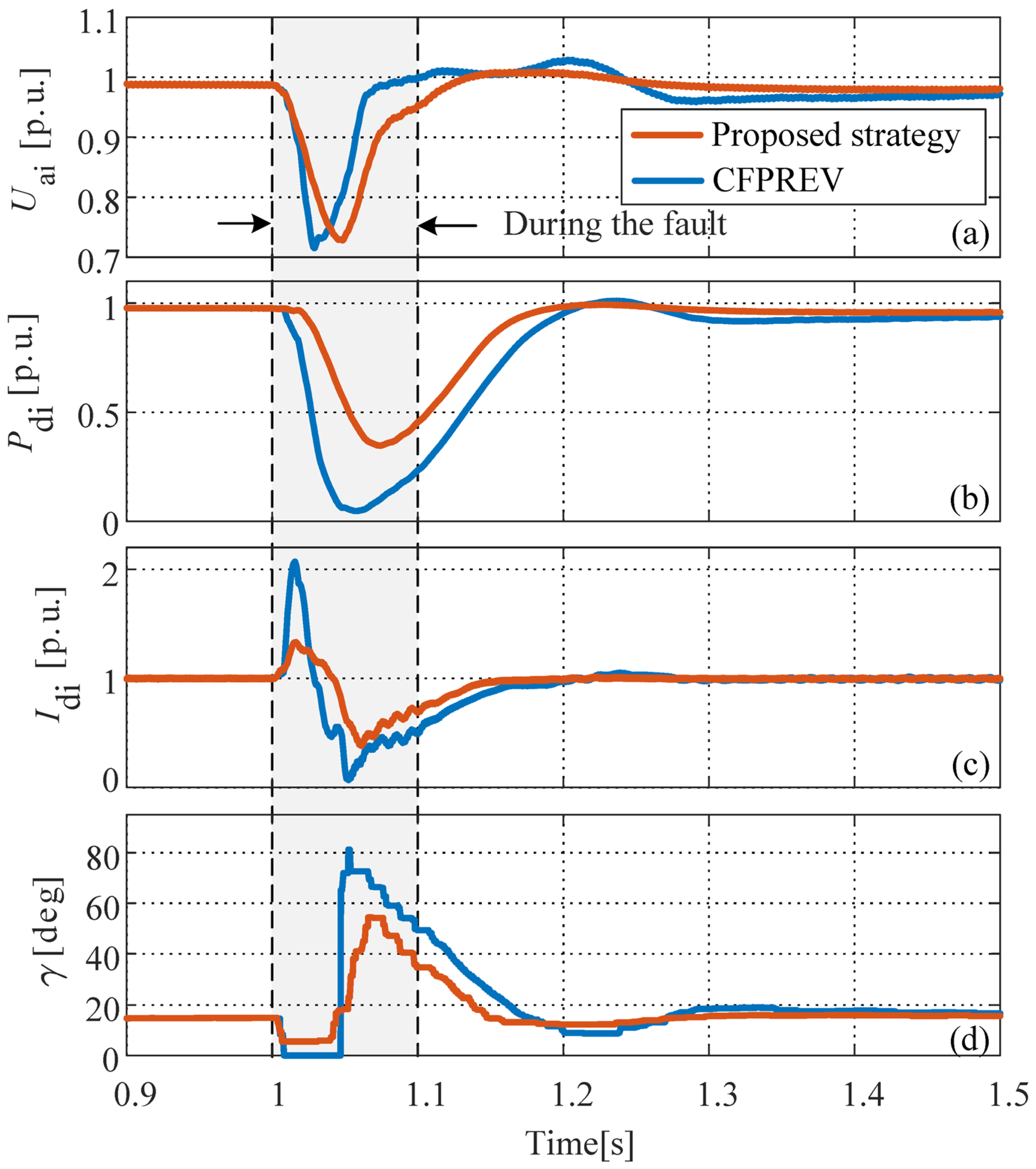
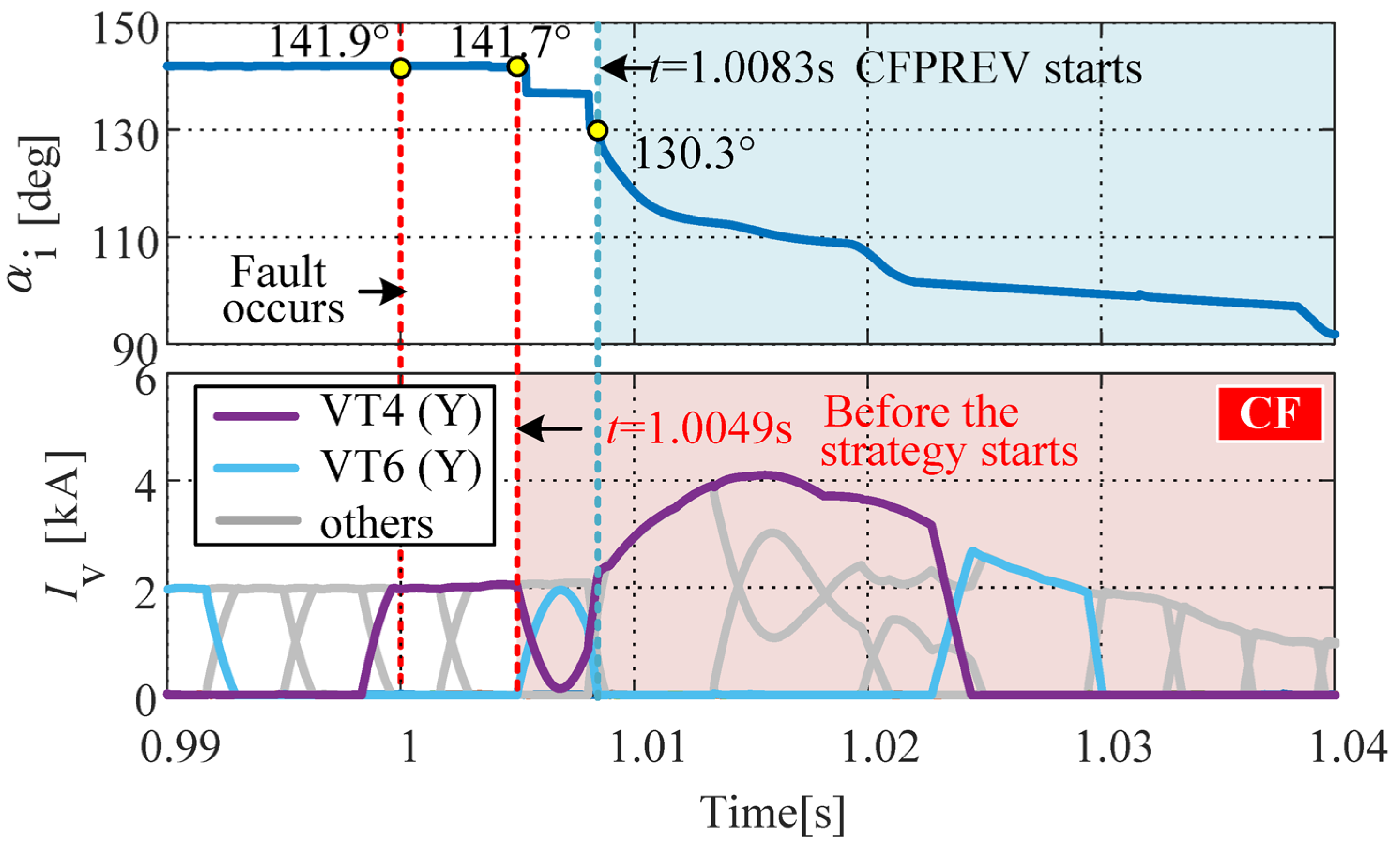
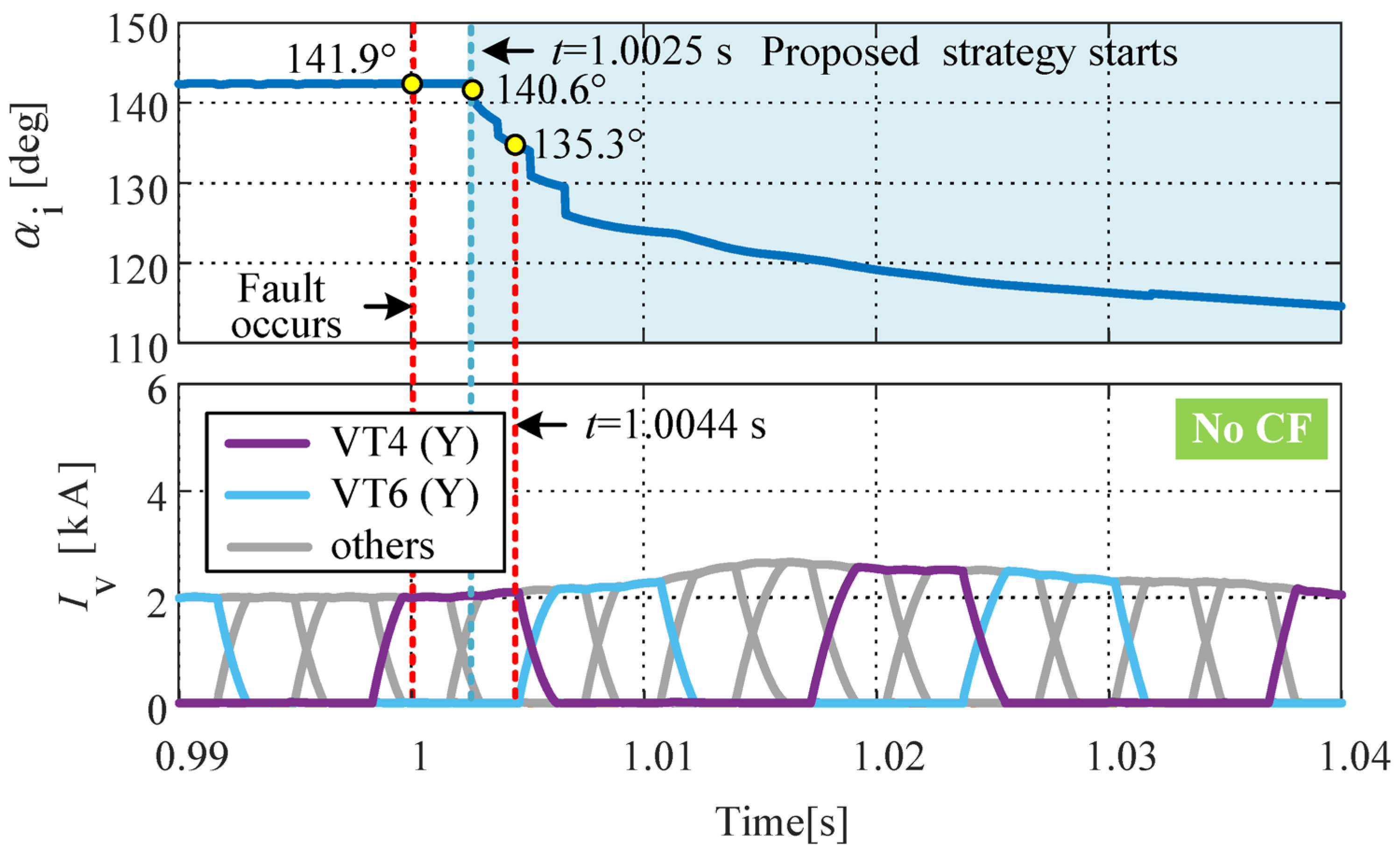
4.2. Analysis of CF Suppression under Typical Fault Scenarios

The CIGRE benchmark model is utilized as the test system in the power systems computer-aided design (PSCAD) program for the simulation illustration of the improved prevention strategy. Consider a three-phase grounding (TPG) fault at the receiving end of LCC–HVDC with a fault inductance of 1.35 H, occurring at 1.0 s and clearing at 1.1 s. The simulation results of the system response under the TPG fault with the traditional CFPREV and the proposed strategy are shown in Figure 6.
As can be seen in Figure 6, the AC voltage in the receiving end, Uai, drops rapidly after the fault occurs, with a fast decrease in γ. Thus, the risk of CF increases greatly. Under the traditional CFPREV, γ drops to zero, which means that CF occurs. Therefore, Idi surges to twice the rated value, and the DC transmission power at the inverter, Pdi, decreases rapidly. Under the proposed strategy, the converter can effectively realize the advanced trigger control, which raises γ from zero to 5.76° without an occurrence of CF. Meanwhile, the surge of Idi and the decrease in Pdi are also effectively suppressed.
Moreover, the response speed of the traditional CFPREV and the proposed strategy are compared under the same fault conditions. Simulation results are given in Figure 7 and Figure 8.
As can be seen in Figure 7, αi stays at 141.9° during the normal stage. After the fault occurrence and before the input of the traditional CFPREV, αi presents a step-like decrease by CEA control at the inverter [32]. The traditional CFPREV starts at 1.0131 s, by which time αi has dropped to 133.4°. However, a new commutation cycle from commutation valve 2 to valve 6 is triggered at 1.0130 s, which is earlier than the initiation of the traditional CFPREV. Consequently, despite the rapid decrease in αi after the strategy activation, it proves ineffective to intervene in this commutation, ultimately resulting in a failed commutation. Thus, the commutator valve 2 conducts again, with the occurrence of CF. In comparison, the proposed strategy starts at 1.0047 s, allowing for a faster decrease in αi, as shown in Figure 8. During the quick decrease in αi, the moment of commutation from valve 2 to valve 6 is advanced from 1.0131 s to 1.0123 s. This indicates that the proposed strategy can intervene effectively before the commutation event, ultimately resulting in a decrease in αi to 125.5°. Therefore, there is a sufficient commutation margin to prevent the occurrence of CF.
Taking into account the differing responses in the commutation process under different fault types, it is necessary to verify the adaptability of the proposed strategy under other fault scenarios. The simulation for a single line-to-ground (SLG) fault and a phase-to-phase fault is presented. Consider an SLG fault with a fault inductance of 0.7 H that occurs at 1 s and is cleared at 1.1 s. The corresponding simulation results of the system response are shown in Figure 9, Figure 10 and Figure 11. Moreover, consider a phase-to-phase fault with a fault inductance of 1.25 H, occurring at 1 s and clearing at 1.1 s. The corresponding simulation results of the system response are shown in Figure 12, Figure 13 and Figure 14.
As can be seen in Figure 9 and Figure 12, CF occurs under both SLG and phase-to-phase fault scenarios. The response trends of electrical quantities including Uai, Pdi, Idi, and γ are consistent with those under TPG faults. After using the proposed strategy, γ increases from zero to 5.59° in the SLG scenario and to 3.62° in the phase-to-phase fault scenario, effectively mitigating the occurrence of CF.
As illustrated in Figure 10 and Figure 11, with the proposed strategy, the initiation time under the SLG fault is advanced from 1.0083 s to 1.0025 s. Similarly, as shown in Figure 13 and Figure 14, the strategy’s activation moment is also advanced from 1.0038 s to 1.0024 s. This earlier intervention in the commutation by the proposed strategy allows for the advancement of the subsequent critical commutation process, thereby ensuring a large commutation margin.

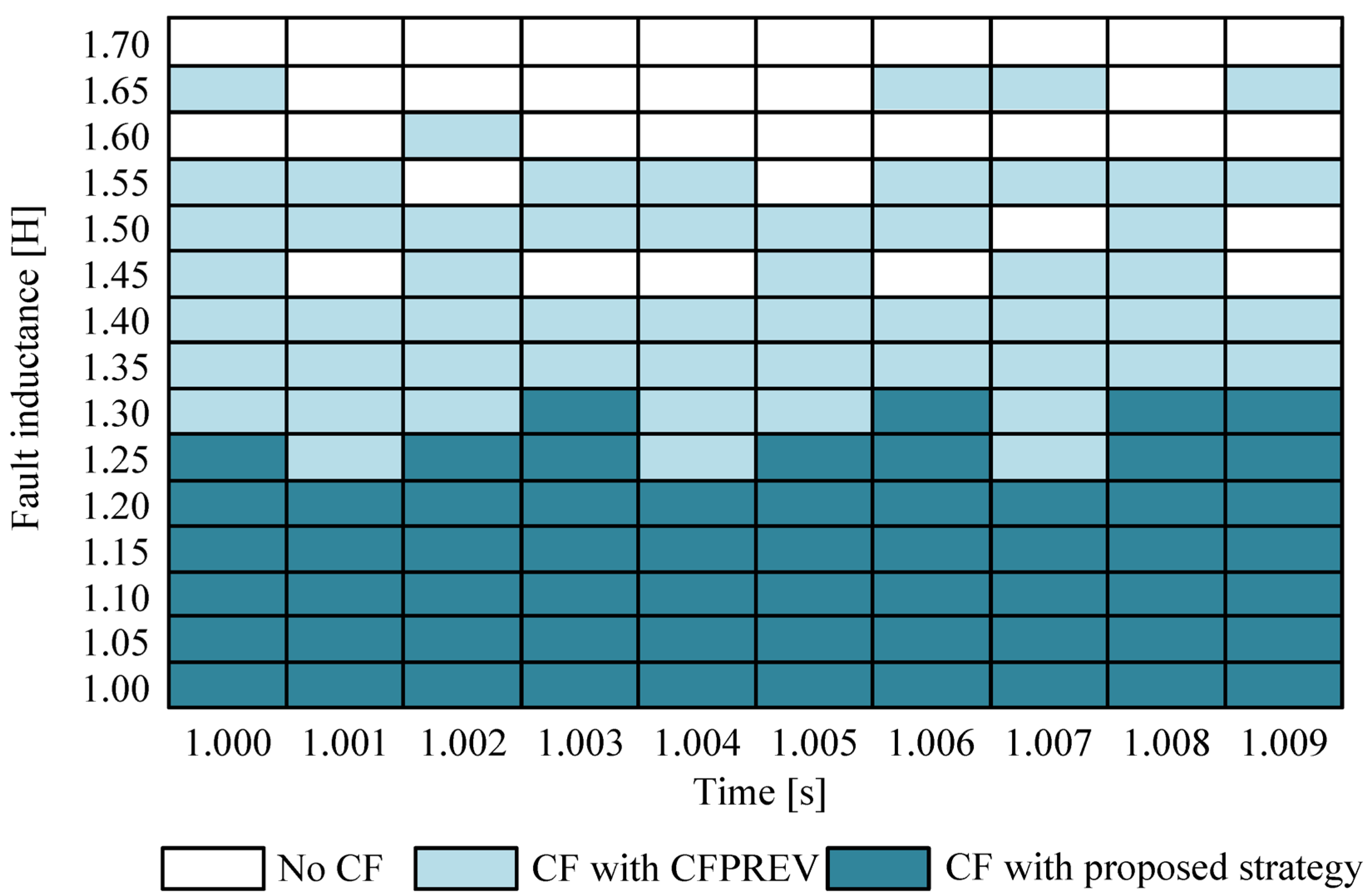
4.3. Statistical Analysis of CF Suppression Effect under Various Fault Conditions

To further validate the effectiveness of the proposed strategy, TPG faults with various fault conditions including fault inductance and fault occurrence times are simulated in this section. Different inductance values represent different fault severities, with lower inductance indicating a more serious fault. Additionally, different fault occurrence times characterize the influence of random fault moments on the commutation process. The simulation results are shown in Figure 15. The fault occurrence time varies from 1.000 s to 1.009 s in steps of 0.001 s, covering half of a period. The fault inductance ranges from 1.00 H to 1.70 H in steps of 0.05 H, resulting in a total of 150 simulations.
As shown in Figure 15, for severe faults with inductance values ranging from 1.00 H to 1.20 H, neither the traditional CFPREV nor the proposed strategy effectively mitigate the occurrence of CF. However, as the fault severity decreases within the range of 1.25 H–1.70 H, the proposed strategy proves more effective, successfully suppressing CF in most fault scenarios. In summary, out of the 150 simulated fault conditions, the proposed strategy effectively suppressed CF in 89 cases, compared to only 34 cases for the traditional CFPREV. Therefore, the proposed strategy exhibits superior CF suppression performance compared to traditional CFPREV.

5. Discussion

This paper proposes an improved prevention strategy based on fault probability detection for CF. The rapid detection of AC faults at the receiving end of LCC–HVDC is the premise for mitigating the risk of CF. Instead of relying on traditional detection methods that compare discrete data points with fixed thresholds, we dynamically evaluate the probability of fault occurrence within a continuous data sequence. This approach facilitates faster and more reliable fault detection at fault inception, accelerates the response time of CF prevention controls, and improves the ability to cope with moderate faults, ultimately leading to the effective prevention of CF.
In practical HVDC projects, CFPREV control is widely equipped on the inverter side. It triggers when detecting AC faults at the receiving end of the LCC–HVDC system to prevent the occurrence of CF. The input of CFPREV is the three-phase AC voltage, while its output is the degree of firing angle advance. The input and output variables of the proposed strategy are consistent with those of CFPREV. In practical engineering projects, it can be directly connected to the control input and output interfaces of CFPREV, allowing for a straightforward replacement and implementation. The essential cause of CF is the commutation voltage dip caused by AC faults at the receiving end of LCC–HVDC, which subsequently leads to a rapid decrease in the extinction angle of the inverter. However, the extinction angle is not solely influenced by external factors but can be actively managed through adjustments in the firing angle. Given that voltage gradually declines after a fault, instead of an abrupt change, various measures can be employed to anticipate and detect faults during the transient process. Consequently, by increasing the extinction angle, the risk of CF can be mitigated. The key to successful prevention lies in achieving effective early triggering before the occurrence of CF; thus, the speed and accuracy of fault detection are of paramount importance. In practical use, the strategy replaces CFPREV control, enabling faster fault detection at the initial fault instance. This enhancement strengthens the resilience of the system to avoid CF occurrence.
The algorithm introduced in this paper relies on mathematical operations, avoiding complex computations, data training, or iterations. Therefore, the proposed strategy does not significantly increase computational complexity compared to that of CFPREV. Moreover, the algorithm will be integrated into the HVDC control and protection cabinet like traditional methods, without any additional costs. In terms of real-time performance, the algorithm is based on the dataset that updates in sync with real-time voltage data, ensuring prompt responses.
In [33,34], the idea of commutation failure suppression from the perspective of current and voltage prediction has been proposed, which aims to accelerate the speed of post-fault advance firing similarly to this paper and to ensure the commutation margin of the converter valve. However, the methods discussed above essentially rely on discrete sampling data and criterion comparison to determine the presence of a fault. In practical engineering applications, the response speed of the control may be limited due to noise, harmonics, and other factors, which potentially impact the effectiveness of commutation failure suppression. In contrast, the strategy presented in this paper calculates the conditional probability for each data point within a dynamic dataset and fuses it to form a fault expectation index. This approach effectively distinguishes between data fluctuation and initial fault condition, theoretically enhancing fault detection speed and reliability, thereby contributing to better suppression results of commutation failure.

6. Conclusions

In this paper, an improved prevention strategy is proposed, which is based on a fault probability detection algorithm. Unlike traditional CFPREV, this strategy refines the detection logic by considering the probability of a fault occurring within a continuous data sequence, rather than comparing individual data points to a threshold. By modifying the existing CFPREV framework, an improved prevention strategy was developed. Notably, during the initial stages of faults, the proposed strategy offers a more rapid response, which is crucial for mitigating the risk of CF. The validity of this method is supported by theoretical analysis and case studies. Simulations in PSCAD initially demonstrated that the proposed algorithm’s fault detection speed is superior to traditional threshold-based methods, using comprehensive datasets from real-world HVDC projects. The effectiveness of the proposed strategy was further validated under various fault scenarios, including TPG, SLG, and phase-to-phase faults. Finally, the overall performance of the proposed strategy is confirmed by extensive simulations across different fault occurrence times and fault severities. Future work will focus on optimizing the strategy for alternative HVDC systems, particularly leveraging AC bus voltage in modular multilevel converters (MMCs) to enhance rapid fault identification in the hybrid cascade HVDC system.

Author Contributions

Methodology, Y.X., Y.Z. and L.L.; Validation, X.L. and Y.T.; Formal analysis, Y.Z.; Investigation, Z.G. All authors have read and agreed to the published version of the manuscript.

Funding

This research was funded in part by China Postdoctoral Science Foundation under Grant 2022MD713744 and in part by National Natural Science Foundation of China under Grant U2166602.

Data Availability Statement

Data are unavailable due to privacy.

Conflicts of Interest

Authors Ying Xu and Zijian Gao were employed by the company State Grid Economic and Technological Research Institute Co., Ltd. The remaining authors declare that the research was conducted in the absence of any commercial or financial relationships that could be construed as a potential conflict of interest.

References

  1. Li, D.; Gao, Y.; Sun, M. A General Self-Adaptive DC Current Control of LCC-HVDC for Eliminating Subsequent Commutation Failure. IEEE Trans. Power Deliv. 2023, 38, 2232–2235. [Google Scholar] [CrossRef]
  2. Guo, Y.; Tan, Z.; Li, X.; Wang, Y.; Liu, Z.; Cai, Z.; Chen, Z. A Hierarchical Identification Method of Commutation Failure Risk Areas in Multi-Infeed Lcc-Hvdc Systems. IEEE Trans. Power Syst. 2024, 39, 2093–2105. [Google Scholar] [CrossRef]
  3. Zhang, G.; Xiang, W.; Han, M.; Zuo, W.; Zhou, M.; Wen, J. DC Impedance Modeling of Push-Pull DC Auto-Transformer for MMC and LCC HVDC Interconnections. IEEE Trans. Power Deliv. 2023, 38, 2441–2453. [Google Scholar] [CrossRef]
  4. Zhu, R.; Zhou, X.; Xia, H.; Hong, L.; Yin, H.; Deng, L.; Liu, Y. Commutation Failure Mitigation Method Based on Imaginary Commutation Process. J. Mod. Power Syst. Clean Energy 2022, 10, 1413–1422. [Google Scholar] [CrossRef]
  5. Zhou, B.; Fang, J.; Ai, X.; Yang, C.; Yao, W.; Wen, J. Dynamic Var Reserve-Constrained Coordinated Scheduling of LCC-HVDC Receiving-End System Considering Contingencies and Wind Uncertainties. IEEE Trans. Sustain. Energy 2021, 12, 469–481. [Google Scholar] [CrossRef]
  6. Song, J.; Li, Y.; Zeng, L.; Zhang, Y. Review on Commutation Failure of HVDC Transmission System. Autom. Electr. Power Syst. 2020, 44, 2–13. [Google Scholar]
  7. Zhou, H.; Yao, W.; Ai, X.; Zhang, J.; Wen, J.; Li, C. Coordinated power control of electrochemical energystorage for mitigating subsequent commutation failures of HVDC. Int. J. Electr. Power Energy Syst. 2022, 134, 107455. [Google Scholar] [CrossRef]
  8. Liu, D.; Zou, C.; Li, X.; Lin, B.; Liu, J.; Jin, T. Suppression of continuous commutation failure in LCC-HVDC transmission based on improved virtual synchronous generator control for energy storage system. Int. J. Electr. Power Energy Syst. 2024, 159, 110018. [Google Scholar] [CrossRef]
  9. Xing, C.; Chen, J.; Xu, Z.; Xi, X.; He, X.; Chen, S. Research on battery energy storage STATCOM suppressing HVDC commutation failure. Front. Energy Res. 2022, 10, 865620. [Google Scholar] [CrossRef]
  10. Xu, C.; Yu, Z.; Zhao, B.; Chen, Z.; Wang, Z.; Ren, C.; Zeng, R. A novel hybrid line commutated converter based on IGCT to mitigate commutation failure for high-power HVDC application. IEEE Trans. Power Electron. 2021, 37, 4931–4936. [Google Scholar] [CrossRef]
  11. Deng, L.; Zhou, X.; Hong, L.; Yin, H.; Zhu, R. A damping-controllable-commutated converter for mitigating commutation failure of LCC-HVDC. IEEE Trans. Power Deliv. 2023, 38, 4371–4383. [Google Scholar] [CrossRef]
  12. Yu, Z.; Wang, J.; Liu, Y.; Fu, C.; He, Q.; Wu, Q.; Wen, Z. An Improved Synchronous Firing Control on Suppressing LCC-HVDC Commutation Failures Caused by Single-Phase-Grounding Faults. IEEE Trans. Power Deliv. 2023, 38, 3875–3887. [Google Scholar] [CrossRef]
  13. Lu, J.; Yuan, X.; Zhang, M.; Hu, J. Supplementary Control for Mitigation of Successive Commutation Failures Considering the Influence of PLL Dynamics in LCC-HVDC Systems. CSEE J. Power Energy Syst. 2022, 8, 872–879. [Google Scholar]
  14. Tian, D.; Xiong, X. Corrections of Original CFPREV Control in LCC-HVDC Links and Analysis of Its Inherent Plateau Effect. CSEE J. Power Energy Syst. 2022, 8, 10–16. [Google Scholar]
  15. Zhang, L.; Dofnas, L. A Novel Method to Mitigate Commutation Failures in HVDC Systems. In Proceedings of the International Conference on Power System Technology, Kunming, China, 13–17 October 2002; Volume 1, pp. 51–56. [Google Scholar]
  16. Chen, S.; Li, X.; Yu, J.; Li, T.; Lu, P.; Yin, Y. A Method Based on the Sin-Cos Components Detection Mitigates Commutation Failure in HVDC. Proc.-Chin. Soc. Electr. Eng. 2005, 25, 1. [Google Scholar]
  17. Li, X.; Chen, S.; Pang, G.; Lei, X.; Liu, Y. Optimization of Commutation Failure Prevention and Automatic Recovery for East China Multi-Infeed High-Voltage Direct Current System. Autom. Electr. Power Syst. 2015, 39, 134–140. [Google Scholar]
  18. Chao, Z.; Zhou, J.; Li, H.; Wan, L.; Sun, H. Impact of Commutation Failure Prediction Control on Voltage Stability and Its Optimization Measures. Autom. Electr. Power Syst. 2016, 40, 179–183. [Google Scholar]
  19. Cheng, F.; Yao, L.; Wang, Z.; Liu, C.; Wang, Q.; Deng, J.; Lan, T. A Commutation Failure Mitigation Strategy Based on Virtual Phase Lock Loop Voltage. Proc. CSEE 2020, 40, 2756–2766. [Google Scholar]
  20. Wang, Z.; Fu, C.; Wang, J.; Li, Z.; Wang, X. Study on the Influence of Phase-locked Loop on Follow-up Commutation Failure of HVDC System. Proc. CSEE 2019, 39, 6836–6844. [Google Scholar]
  21. Wang, Z.; Wang, J.; Fu, C.; Li, Z. Individual Phase Control of High Voltage Direct Current Based on Single-phase Locked Loop. Autom. Electr. Power Syst. 2018, 42, 160–165. [Google Scholar]
  22. Gong, Y.; Wang, J.; Wang, Z.; Fu, Z. A Novel Phase-locked Loop for HVDC. Power Syst. Technol. 2019, 43, 4097–4105. [Google Scholar]
  23. Zhu, J.; Li, Y.; Duan, X. A Constant Extinction Area Based Control Strategy for Suppressing Commutation Failure in Hybrid Dual-Infeed HVDC System. Power Syst. Technol. 2018, 42, 3735–3743. [Google Scholar]
  24. Zhou, B.; Li, F.; Yin, C. A Novel Method to Predict and Prevent Commutation Failures in LCC-HVDC Systems. Int. J. Electr. Power Energy Syst. 2023, 144, 108399. [Google Scholar] [CrossRef]
  25. Yousaf, M.Z.; Liu, H.; Raza, A.; Mustafa, A. Deep Learning-Based Robust DC Fault Protection Scheme for Meshed HVDC Grids. CSEE J. Power Energy Syst. 2023, 11, 2423–2434. [Google Scholar]
  26. Yousaf, M.Z.; Khalid, S.; Tahir, M.F.; Tzes, A.; Raza, A. A novel dc fault protection scheme based on intelligent network for meshed dc grids. Int. J. Electr. Power Energy Syst. 2023, 8, 109423. [Google Scholar] [CrossRef]
  27. Yousaf, M.Z.; Mirsaeidi, S.; Khalid, S.; Raza, A.; Zhichu, C.; Rehman, W.U.; Badshah, F. Multisegmented Intelligent Solution for MT-HVDC Grid Protection. Electronics 2023, 12, 1766. [Google Scholar] [CrossRef]
  28. Yousaf, M.Z.; Tahir, M.F.; Raza, A.; Khan, M.A.; Badshah, F. Intelligent Sensors for dc Fault Location Scheme Based on Optimized Intelligent Architecture for HVdc Systems. Sensors 2022, 12, 9936. [Google Scholar] [CrossRef]
  29. Benasla, M.; Allaoui, T.; Brahami, M.; Boudali, A.; Chedni, Y. Study and Simulation of Hvdc System in Dynamic Condition. In Proceedings of the 3rd International Conference on Systems and Control, Algiers, Algeria, 29–31 October 2013; pp. 276–281. [Google Scholar]
  30. Liu, L.; Li, X.; Teng, Y.; Chen, K.; Tang, Y. An Improved Commutation Failure Prevention Control for Hybrid Cascaded UHVDC System. In Proceedings of the 2023 Panda Forum on Power and Energy (PandaFPE), Chengdu, China, 27–30 April 2023; pp. 55–59. [Google Scholar]
  31. Nguyen, D.T.; Duong, Q.B.; Zamaï, É.; Shahzad, M.K. Bayesian Network Model with Dynamic Structure Identification for Real Time Diagnosis. In Proceedings of the 2014 IEEE Emerging Technology and Factory Automation (ETFA), Barcelona, Spain, 16–19 September 2014; pp. 1–8. [Google Scholar]
  32. Liu, L.; Lin, S.; Sun, P.; Liao, K.; Li, X.; Deng, Y.; He, Z. A Calculation Method of Pseudo Extinction Angle for Commutation Failure Mitigation in HVDC. IEEE Trans. Power Deliv. 2019, 34, 777–779. [Google Scholar] [CrossRef]
  33. Zhou, B.; Li, F.; Song, X.; Yin, C. Commutation Failure Prediction and Control System Optimization Based on DC Current Variation. Power Syst. Technol. 2019, 43, 3497–3504. [Google Scholar]
  34. Zhou, H.; Yao, W.; Li, J. Commutation Failure Prevention Strategy of HVDC Based on Current and Voltage Prediction. Proc. CSEE 2022, 42, 5948–5959+6169. [Google Scholar]
Figure 1. The schematic diagram of controllers in the CIGRE Benchmark model.
Electronics 13 03804 g001
Figure 2. The schematic diagram of CFPREV.
Electronics 13 03804 g002
Figure 3. Diagram of the proposed fault probability detection algorithm.
Electronics 13 03804 g003
Figure 4. The schematic diagram of the improved prevention strategy.
Electronics 13 03804 g004
Figure 5. Comparison of different fault detection methods based on actual project fault data.
Electronics 13 03804 g005
Figure 6. Simulation results of system response under the TPG fault with the traditional CFPREV and the proposed strategy. (a) AC voltage in the receiving end. (b) Transmission power at the inverter. (c) DC current at the inverter. (d) Extinction angle at the inverter.
Electronics 13 03804 g006
Figure 7. Performance of the traditional CFPREV under the TPG fault.
Electronics 13 03804 g007
Figure 8. Performance of the proposed strategy under the TPG fault.
Electronics 13 03804 g008
Figure 9. Simulation results of system response under the SLG fault with the traditional CFPREV and the proposed strategy. (a) AC voltage in the receiving end. (b) Transmission power at the inverter. (c) DC current at the inverter. (d) Extinction angle at the inverter.
Electronics 13 03804 g009
Figure 10. Performance of the traditional CFPREV under the SLG fault.
Electronics 13 03804 g010
Figure 11. Performance of the proposed strategy under the SLG fault.
Electronics 13 03804 g011
Figure 12. Simulation results of system response under the phase-to-phase fault with the traditional CFPREV and the proposed strategy. (a) AC voltage in the receiving end. (b) Transmission power at the inverter. (c) DC current at the inverter. (d) Extinction angle at the inverter.
Electronics 13 03804 g012
Figure 13. Performance of the traditional CFPREV under the phase-to-phase fault.
Electronics 13 03804 g013
Figure 14. Performance of the proposed strategy under the phase-to-phase fault.
Electronics 13 03804 g014
Figure 15. Simulation results of different strategies with various fault inductance and occurrence times.
Electronics 13 03804 g015
Table 1. The nomenclature of variables in the control schematic diagram.
Nomenclature
Idr, IdiDC current in the rectifier and inverter, respectively
αr, αiFiring angle order of the rectifier and inverter, respectively
UdiRectifier DC voltage
γRectifier extinction angle
Idord, IdrordSet and actual DC current order, respectively
βrccOutput from the rectifier CC controller
βiccOutput from the inverter CC controller
βrceaOutput from the inverter CEA controller
βiLeading firing angle order in the inverter
ΔγiordExtinction angle compensation
ΔαAdditional firing angle lead order from the CFPREV control
Disclaimer/Publisher’s Note: The statements, opinions and data contained in all publications are solely those of the individual author(s) and contributor(s) and not of MDPI and/or the editor(s). MDPI and/or the editor(s) disclaim responsibility for any injury to people or property resulting from any ideas, methods, instructions or products referred to in the content.

