Article

Investigation of the Role of the Initial Workpiece Diameter in Deformation Control in Electromagnetic Sheet Forming

1
Wuhan Second Ship Design and Research Institute, Wuhan 430205, China
2
Hubei Key Laboratory of Marine Electromagnetic Detection and Control, Wuhan 430205, China
*
Author to whom correspondence should be addressed.
Electronics 2024, 13(19), 3828; https://doi.org/10.3390/electronics13193828
Submission received: 22 January 2024 / Revised: 6 May 2024 / Accepted: 14 May 2024 / Published: 27 September 2024
(This article belongs to the Special Issue Pulsed Magnetic Fields and Its Applications)

Abstract

:
The initial workpiece diameter is one of the most fundamental process parameters in sheet metal forming, as it determines the resistance of the draw-in material flow. In the context of conventional deep drawing, its critical role has been clearly identified. In the context of electromagnetic sheet forming, however, its role has not yet been adequately addressed. This paper aims to clarify its role, by experimentally and numerically investigating the deformation behavior of circular sheet metal in electromagnetic forming. Various combinations of the initial diameter and discharge voltage were established to induce different deformation behaviors. It was found that adjusting the initial diameter can substantially change the forming height, shape, and thickness distribution by altering the draw-in, which suggests a great improvement in deformation controllability. In summary, this study demonstrates that the initial workpiece diameter could play critical role in deformation control in electromagnetic forming.

1. Introduction

There is great motivation to explore flexible and versatile forming processes, which provide the conventional forming community with the benefits of reduced cost and improved quality [1]. Electromagnetic forming (EMF) is amongst the most flexible forming process and is obtaining increased attention. In contrast to conventional forming processes, the EMF process shapes metal workpieces with a high forming velocity (200 m/s) and strain rate (>103/s) using a pulsed Lorentz force, which has several advantages, such as improved formability and solid-state welding [2,3,4,5]. In this way, lots of novel EMF applications have been facilitated, from forming [6,7,8,9,10,11,12,13,14,15,16] to dissimilar-material welding [17,18,19,20].
For the EMF of sheet metal, the flexible control of high-velocity deformation behavior is a basic necessity, but it remains an open problem. It is difficult to flexibly control the forming shape, especially when a large deformation area and a high forming height are simultaneously required. For electromagnetic free-forming processes, the forming shape is generally limited to a cone-shaped geometry, regardless of the discharge voltages [21,22,23]. For the electromagnetic die-impact forming process, remarkable elastic recovery, which is defined by remarkable reversal of the forming velocity when impacted by the die, is likely to occur, resulting in poor forming accuracy [24]. In addition, severe rebounding may further induce several defects like wrinkling [25] and cracking [26].
Various methods have been proposed for better deformation control. The coil geometry is amongst the most common design freedoms, which alters the deformation by tailoring the spatial distribution of the Lorentz force. The flat spiral coil [22] is commonly used, in which the diameter and pitch of the coil winding can be adjusted to alter the Lorentz force distribution. Ahmed et al. [27] further modified the flat spiral coil geometry by introducing variation in the cross-section for the coil conductor; however, no forming results were reported (either experimental nor numerical). Kamal and Daehn [6] proposed a uniform pressure actuator to produce a uniform Lorentz force over a relatively large sheet metal area, showing a great improvement in the deformation behavior. And Lai et al. [28,29] developed an efficient analytical analysis and design procedure for this coil. However, when shaping a cellphone shell part with this coil, the deformation is too aggressive, resulting in tearing at the die corner. To solve this problem, Kamal et al. [30] further proposed a multiple-step process, in which an additional piece of flat sheet metal was used as a driver to transfer the forming force to the deformed workpiece after first-step forming. The sheet driver was also suggested to be able to relieve the elastic recovery [25], thus improving the forming accuracy. However, while the driver sheet can improve the process controllability, it results in increased cost and decreased flexibility. Risch et al. [24] numerically analyzed the effect of the die material on the elastic recovery, identifying the critical significance of the stiffness and damping properties of the die material; however, the creation of a die with ideal properties is not easy, and no further experimental results have been reported.
Addressing the abovementioned state of the art of deformation control in EMF, this paper carries out further exploration of the critical design freedom for deformation control. The roles of one of the most fundamental process parameters, that is, the initial workpiece diameter, are evaluated. Actually, the roles of the initial workpiece diameter in the conventional deep drawing process are clearly identified, revealing its critical influence on workpiece deformation by altering the draw-in (defined as the feeding of the flange metal into the die cavity [31]). In the electromagnetic sheet forming process, the roles of the initial workpiece diameter, however, have not yet been widely addressed. This could be due to the ignoring of the “drawing” deformation in EMF, which is partially attributed to cost considerations. Golovashchenko [32] pointed out that due to the high geometry sensitivity of the Lorentz force, multiple sets of coils may be required for one single drawing process, resulting in a high tool cost. Another reason for ignoring the role of the initial workpiece diameter seems to be intuitive, as it is believed that the draw-in would be inhibited in EMF due to the remarkable inertia of the sheet flange. This point has been mentioned by several studies, such as [21,33]; although a rigorous quantitative evaluation of the contribution from the inertia force is not yet available, current experimental observations seems to support this point.
Despite of the ignoring of the role of the initial workpiece diameter and the underlying reasons, basic sheet forming mechanics [31] clearly support that the initial workpiece diameter could be a critical process parameter to control the draw-in in EMF. According to recent works [21,34,35,36,37,38], controllable draw-in could remarkably improve the deformation behavior of EMF, including a substantial enhancement in the limited forming height (over 140%) and flexible control of the forming shape, in which the sheet bottom geometry can be flexibly altered from convex-shaped, to flat-shaped, and even to concave-shaped. Thereby, it is highly expected that the initial workpiece diameter could play an important role in the electromagnetic sheet forming process.
To evaluate the potential role of the initial workpiece diameter, this paper performed a combination of experiments and numerical simulations on the electromagnetic forming of circular sheet metal. A series of combinations of the initial workpiece diameter and discharge voltage were established to induce different deformation behavior. The changes in the deformation morphology were characterized to evaluate the influence of the initial workpiece diameter. Meanwhile, the process dynamics were numerically analyzed to obtain a better insight into the underlying control mechanism. Finally, the deformation control achieved by introducing the initial workpiece diameter as a design freedom is discussed, in light of the presented experimental and numerical analyses.

2. Materials and Methods

2.1. Experimental Setup

The setup in Figure 1 was adopted for the experimental investigation. Figure 1a shows the experimental assembly, Figure 1b shows the coil geometry and the discharge circuit, and Figure 1c shows the typical waveform for the experimental discharge current. Table 1 presents details of the system parameters.
In the experiments, a 1 mm thick circular aluminum sheet (AA1050-O) was formed using a circular spiral coil. The die had a 70 mm cavity diameter and a 5 mm corner radius, and was made from #45 steel. The air in the die cavity was exhausted using a vacuum pump, controlling the residual pressure within 100 Pa. The coil winding had inner and outer diameters of 20 mm and 74 mm, respectively. It was wound from copper wire with a cross-section of 16 mm × 1.5 mm and with 15 turns. A 0.2 mm thick polyimide film was adopted as electrical insulation between each coil turn. To enhance the coil longevity, the coil was reinforced with high-strength fiber (Zylon, with ultra tensile strength of about 4 GPa) at the outermost part of the coil winding. The coil was energized by a 320 μF capacitor bank. The discharge current had a rise time of about 84 μs (see Figure 1c). Only one pulse existed in this discharge current waveform due to the use of a thyristor as a switch, which allowed the current to flow in only one specific direction.
It should be mentioned that a special clamping mechanism was used in the experiments on inertia confinement, which utilizes the remarkable inertia effects of the tool to resist the axial upward Lorentz force acting on the driving coil [3]. It has been previously utilized in an EMF facility for shaping a sheet metal part with a length scale over 1000 mm [7], suggesting its effectiveness. Herein, inertia confinement was achieved by positioning a 500 kg counterweight on the upper side of the setup. While it provided an effective constraint for the setup, such a clamping mechanism produces only a small blank holding force (BHF). Before the discharge, the counterweight would produce a 5 kN BHF, due to its gravity; during the discharge process, however, a much higher upward counter-Lorentz force (~30 kN) on the forming coil could completely eliminate the 5 kN BHF. The elimination of the BHF is helpful to emphasize the role of the initial workpiece diameter in altering the material flow of the flange region.

2.2. Numerical Simulation

A numerical model similar to that in [34] was adopted to simulate the multi-physics dynamics of EMF. The model involves two sub-models—a mechanical and an electromagnetic model—which considered the interactions among the discharge circuit, the magnetic field, and the workpiece deformation by using a sequential coupling procedure with a 2 μs time step.

2.2.1. Electromagnetic Model

The electromagnetic model was created by using an in-house code developed in [34], whose basic idea is to handle the involved electromagnetic phenomena by establishing its equivalent circuits. Compared to the finite element method, this code eliminates the treatment of distorted air meshing induced by workpiece deformation. Rigorously, the EM model should take all the electric conductors into account, since all of them may induce eddy currents, thus influencing the Lorentz force produced on the workpiece. For the experimental setup shown in Figure 1, apart from the workpiece and the coil, these conductors include the die underneath the workpiece and the counterweight made from steel. However, to reduce the computational cost, our model did not consider their influences; according to our test, such simplification is acceptable. According to [39], the electrical-conductive die (which was made from #45 steel) could shield the axial magnetic field at the sheet edge, thus eliminating the generation of the radial Lorentz force component at the sheet edge. To consider this effect, the radial Lorentz force component at the sheet edge was artificially forced to zero when imposing the Lorentz force loading in the “mechanical model” for deformation analysis.
Details of the parameters used in the EM model can be found in Table 1. For more details about the creation of the model, the readers may refer to [34].

2.2.2. Mechanical Model

Mechanical modeling was achieved by using Ansys/Ls-dyna. The model geometry can be found in Figure 1. Details of the system parameters can be found in Table 1. Due to the highly dynamic nature of the process, the deformation or movement of each component of the experimental assembly shown in Figure 1a may influence the forming process. To involve these potential influences, all of these components were considered and regarded as deformable body in the model, in which the workpiece was regarded as plastic-deformable, and the others were regarded as elastic-deformable. All of them were modeled by the element type of Plane 162 (quadratic element with four nodes). Five layers of elements were set throughout the thickness of the workpiece.
Apart from the Lorentz force acting on the workpiece and the coil, the gravity of the counterweight was also considered in the model, which was linearly loaded from 0 to 5 kN within 5 ms, and then held at 5 kN. In addition, a 0.1 MPa uniform pressure was imposed on the upper surface of the workpiece, to simulate the workpiece deformation induced by the vacuum environment of the die cavity. This pressure was linearly loaded from 0 to 0.1 MPa within 5 ms, and then held at 0.1 MPa. Discharge occurred at 5 ms.
The Cowper–Symonds model was adopted to characterize the flow stress for the workpiece under a high strain rate:
σ = σ q s 1 + ( ε p P ) m
where εp* is the strain rate; P and m are constants, which are 6500 and 0.25, respectively (refer to [40]); and σqs is the measured stress–strain relationship in a quasi-static state, given by the following equation:
σ q s = 131.98 ε p 0.26

2.3. Process Parameter Setup

As listed in Table 2, varied combinations of the initial workpiece diameter and discharge voltage were established to induce different deformation behavior. In the experiments, four workpiece diameters and four discharge voltages were established, composing sixteen parameter combinations; in the numerical simulations, three additional initial workpiece diameters (150, 200, and 300 mm) were provided, composing twenty eight parameter combinations.
In conventional deep drawing, the drawing ratio (DR), which is defined as the ratio of the initial workpiece diameter to the die cavity diameter (70 mm), characterizes the influences of the initial workpiece diameter on the deformation resistance of the draw-in. The larger the DR is, the larger the deformation resistance is, and thus, the smaller the draw-in is. According to [31], the DR has a limiting value (LDR), beyond which the draw-in can be inhibited, and the theoretical LDR is about 2.7. In this study, the DR is 1.36~1.86 for the experiments, and 1.36~4.29 for the simulations. Thereby, it is expected that such a DR range could induce wide variation in the draw-in material flow and thus deformation morphology.

3. Results and Discussion

3.1. Forming Results

To evaluate the influences of the initial workpiece diameter on workpiece deformation, the forming results under varied conditions were analyzed in terms of draw-in, forming height, deformation profile, and thickness distribution.
Figure 2 presents the variation in the draw-in, in which Figure 2a emphasizes its dependence on the discharge voltage, and Figure 2b emphasizes its dependence on the initial workpiece diameter. The numerical simulation effectively reproduces the experimental results, in which the maximum deviation can be limited within 1 mm. In the case of large workpiece diameters (>130 mm), only a small draw-in exists (less than 1 mm), regardless of the discharge voltage, suggesting an inhibited draw-in; by decreasing the diameter below 130 mm, the draw-in can be exponentially enhanced with decreasing diameter, and linearly enhanced with increasing discharge voltage. The above observations suggest a critical role of the initial workpiece diameter in altering the draw-in material flow.
Figure 3 presents the variation in the forming height. The numerical simulation effectively reproduces the experimental observations, in which the maximum deviation can be limited within 3 mm. It is noted that the initial workpiece diameter also substantially affects the forming height, in which the decreased workpiece diameter results in an exponential increase in the forming height (about a 40% increment can be observed). This can be explained by the exponentially increased draw-in observed in Figure 2, which feeds substantial flange metal into the die cavity, contributing to the increased forming height.
Figure 4 shows the variations in the deformation profile and thickness reduction. Only the numerical results are presented; as indicated by Figure 2 and Figure 3, the adopted simulation can provide a reliable reflection of the real experimental results. Figure 4a,b present the deformation results when inhibiting the draw-in (holding a 300 mm initial workpiece diameter). The results suggest that the forming shape remains cone-shaped, regardless of the discharge voltage. In addition, the thinning is obviously intensified with the forming height. Figure 4c,d present the results obtained when gradually increasing the draw-in (by decreasing the workpiece diameter). The results suggest that a perpendicular side-wall can be formed in the die corner region, and the overall thickness reduction can be effectively relieved. When decreasing the diameter from 300 to 95 mm, the maximum thinning (at sheet center) can be relieved by 27% (from 33% to 24%). These results suggest a critical role of the initial workpiece diameter in controlling the deformation morphology.

3.2. Analysis of Loading Process

According to the above section, it becomes clear that the initial workpiece diameter is a critical process parameter to control the deformation behavior in EMF. In the following section, the process dynamics shall be further detailed, thus providing a better understanding of the underlying influencing mechanism. Prior to detailing the deformation history (Section 3.3), the dynamic loading process is analyzed to reveal the spatial and temporal features of the Lorentz force and the energy conversion process, which is critical to understanding the deformation behavior.
Two comparative cases are analyzed herein with the same discharge voltage (5 kV) but different initial workpiece diameters (300 and 95 mm). Figure 5a,b present the Lorentz force distribution at four typical times, and Figure 5c,d present the conversion of the EM work (mechanical work exerted by the Lorentz force), kinetic energy, and plastic energy.
The results in Figure 5 suggest a similar Lorentz force distribution for the two workpieces, both of which are concentrated underneath the coil winding and rapidly decay with time due to the accumulated workpiece deformation. These similar Lorentz forces result in similar EM work courses for the two workpieces, which overlap with each other at the initial stage (see Figure 5c). Although they deviate from each other at the later stage, the final deviation can be limited within 7.7%, in which the smaller initial diameter leads to slightly greater EM work.
The effective action of the pulsed Lorentz force may finish at about 120 μs. As indicated by Figure 5a,b, after 120 μs, the Lorentz force in the unsupported sheet region, which is the portion that actually contributes to the workpiece acceleration, is substantially decayed. According to the EM work course shown in Figure 5c, over 94% of the total EM work is obtained within 120 μs, and less than 6% of EM work is supplied after this. Notably, the courses of plastic and kinetic energy show that the total deformation duration is about 220~350 μs; at the time period between 120 μs and 220~350 μs, the workpiece deformation is dominated by its inertia effect. Therefore, the whole deformation process can be divided into two distinguished stages, that is, the Lorentz force action stage and the inertia-force-dominated stage.
Regarding the extraction of the EM work, kinetic energy, and plastic strain energy at 120 μs (see Figure 5d), while the EM work is weakly related to the workpiece diameter, the kinetic energy is strongly related to the workpiece diameter. When decreasing the initial workpiece diameter from 300 mm to 95 mm, the accumulated kinetic energy (at 120 μs) can be increased by 47% (28.6 J). This implies a substantial change in the velocity field, which is responsible for the observed changes in the deformation morphology. The evolutions of the kinetic and plastic energies (see Figure 5c) further imply that the major changes in the deformation behavior of the two workpieces may occur after 120 μs, that is, the inertia-force-dominated stage. This point shall be detailed in the next section.

3.3. Analysis of Deformation History

After analyzing the loading process, this section further details the deformation histories for ∅300 mm and ∅95 mm workpieces. Figure 6a presents the evolutions of the deformation profiles, Figure 6b–d present the axial velocity, plastic strain, and strain rate at the sheet center, and Figure 6e presents the draw-in evolution for the 95 mm workpiece. The sheet center strain and strain rate in Figure 6c–e are extracted from the workpiece surface that is far away from the coil, in which the severest bi-axial stretching is observed.
According to the analysis of the loading process (see Figure 5 in Section 3.2), the whole deformation process was divided into the Lorentz force action stage (“green box”) and the inertia-force-dominated stage (“blue box”), which are differentiated by a period of 120 μs.
The results clearly show that the two workpieces have similar deformation behavior at the Lorentz force action stage, and the major changes in the deformation of the two workpieces occur at the inertia-force-dominated stage. This could be explained by the evolution of the draw-in for the 95 mm workpiece, shown in Figure 6e (the draw-in for the 300 mm workpiece is close to 0; see Figure 2). As we can see, at the Lorentz force action stage, although the draw-in velocity is gradually increased and reaches its peak (about 53 m/s) at the end of this stage, the accumulated draw-in displacement remains small at 2.19 mm, only 22% of the total draw-in (8.75 mm). This limited draw-in consequently results in limited changes in the deformation behavior of the two workpieces.
At the inertia-force-dominated stage, however, the draw-in is obviously increased, thus substantially changing the deformation behavior.
The increased draw-in in the case of the 95 mm workpiece feeds substantial metal into the die cavity, assisting in the gradual formation of the perpendicular side-wall close to die corner region (see Figure 6a).
In addition, the increased draw-in results in about a 9% decrease in the peak axial velocity and about a 69% increase in the deformation duration (see Figure 6b), which is responsible for the 40% increase in the forming height, as presented in Figure 3. The 9% decreased axial velocity implies relief of the deformation severity, which may partly contribute to better deformation uniformity. The axial velocity course has a “tail” (between 238 and 354 μs) for the 95 mm workpiece. As indicated by the courses of the plastic strain and plastic strain rate (see Figure 6c,d), this duration shows no plastic deformation at the sheet center. Thereby, this “tail” is attributed to a pure drawing deformation mode; herein, it contributes to about 6% of the total forming height.
The peak strain rates for the 300 mm and 95 mm workpieces are 1.15 × 10⁴/s and 1.32 × 10⁴/s (see Figure 6d), respectively, suggesting that increased draw-in is not necessary to reduce the plastic strain rate. However, the increased draw-in induces a 27% decrease in the second pulse duration for the plastic strain rate, which results in a 22% decrease in the plastic strain (see Figure 6c), and thus, a 27% relieved thinning rate (see Figure 4).

3.4. Implications on Deformation Control

Regarding the poor controllability on the forming shape in EMF (as analyzed in the “Introduction” Section, also indicated in Figure 4a), the results in this paper (Section 3.1, Section 3.2 and Section 3.3) imply that the initial workpiece diameter could be a useful design freedom for deformation control. Better controllability of the forming shape could be obtained by combining the initial workpiece diameter with other process parameters, such as the discharge voltage and the coil geometry. According to the loading process (see Figure 5) and the deformation history (see Figure 6), the discharge voltage and the coil geometry could dominate the deformation control at Lorentz force action stage (by affecting the spatial–temporal features of the Lorentz force), while adjusting the initial diameter enables the further regulation of deformation at the inertia-force-dominated stage. The combined control of these then enables better regulation of the deformation dynamics, thus enhancing the controllability of the final deformation morphology. In this way, the forming shape made available by EMF can be extended.
To illustrate this point, Figure 7 gives an example of deformation control which is achieved by simultaneously adjusting the discharge voltage and the workpiece diameter. These results present continuous variations in the forming shape while holding same forming height, which suggests effective shape control. Although these results (presented in Figure 7) are focused on the electromagnetic free-forming process, it is expected that such improved shape control is helpful in electromagnetic die-impact forming as well, where the elastic recovery is of great concern [24]. This is beneficial for improving the forming accuracy.
In Figure 7, it is also noted that, compared to the process where draw-in is severely inhibited (such as in the case of the 300 mm workpiece), the discharge voltage required to obtain the same forming height can be obviously reduced when increasing drawing deformation (such as in the case of the 95 mm workpiece). About a 25% decrease in the discharge voltage can be observed (from 6.7 kV to 5 kV), leading to about a 44% decrease in the discharge energy (from 7.2 kJ to 4 kJ), indicating an obvious increase in forming efficiency.

4. Conclusions

Addressing the open question on controlling high-velocity deformation behavior in EMF, this paper evaluated the role of the initial workpiece diameter in deformation control in the electromagnetic forming of circular sheet metal. Specifically, the following conclusions can be drawn:
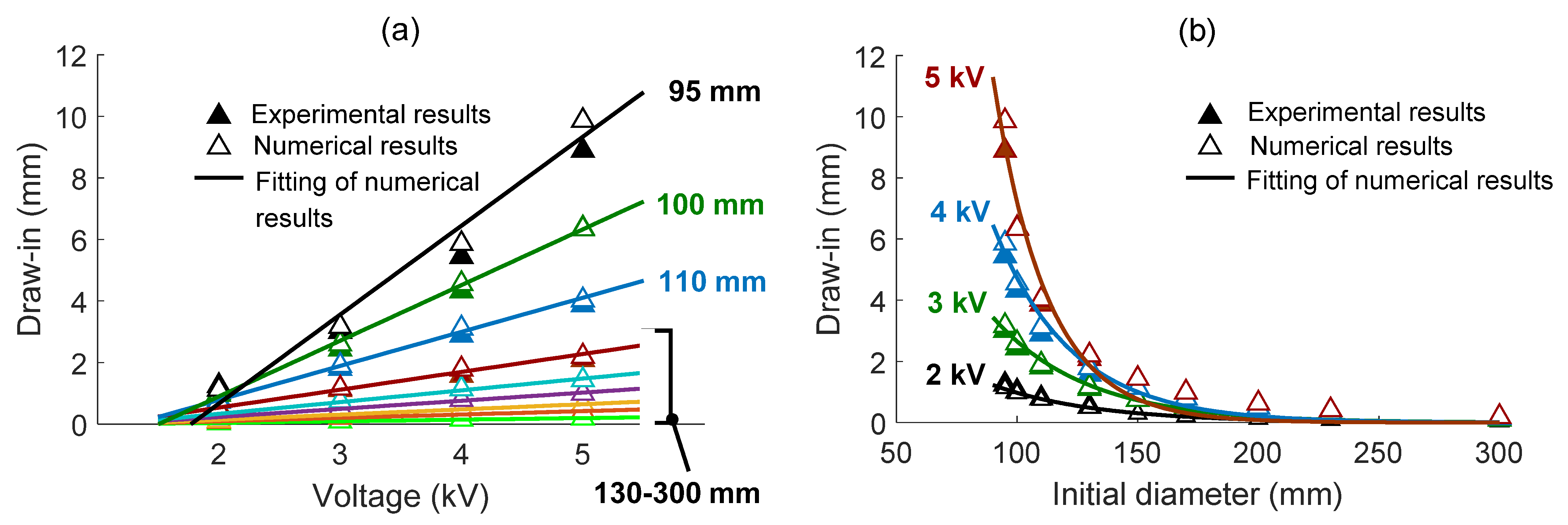
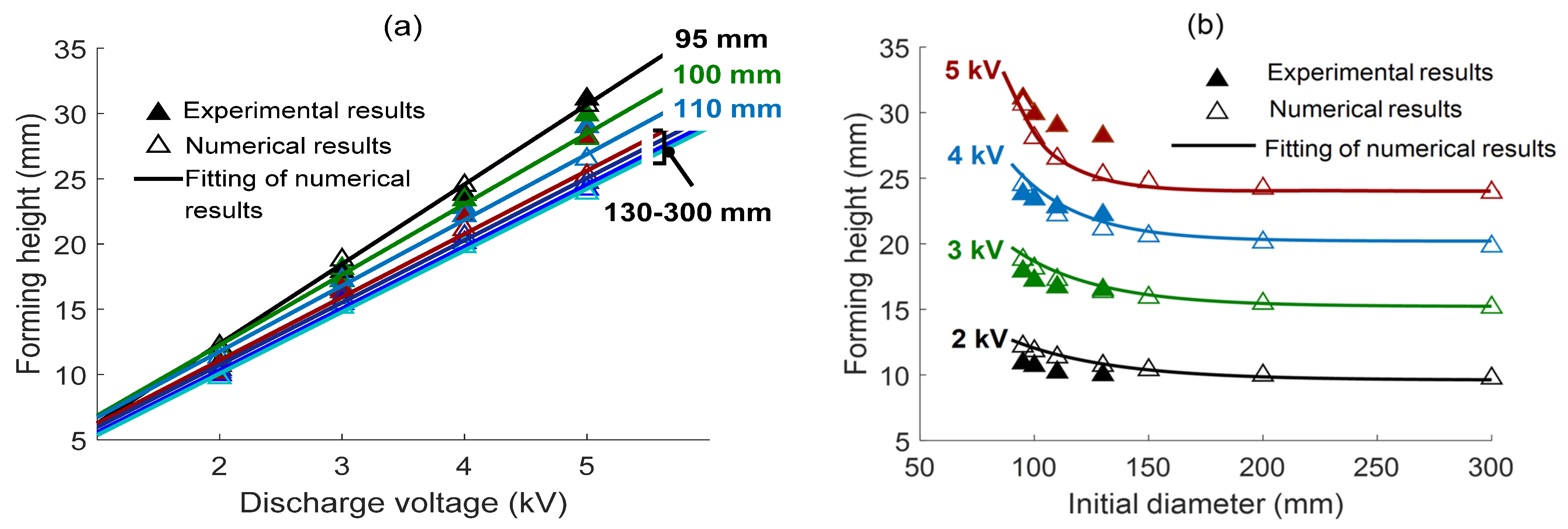
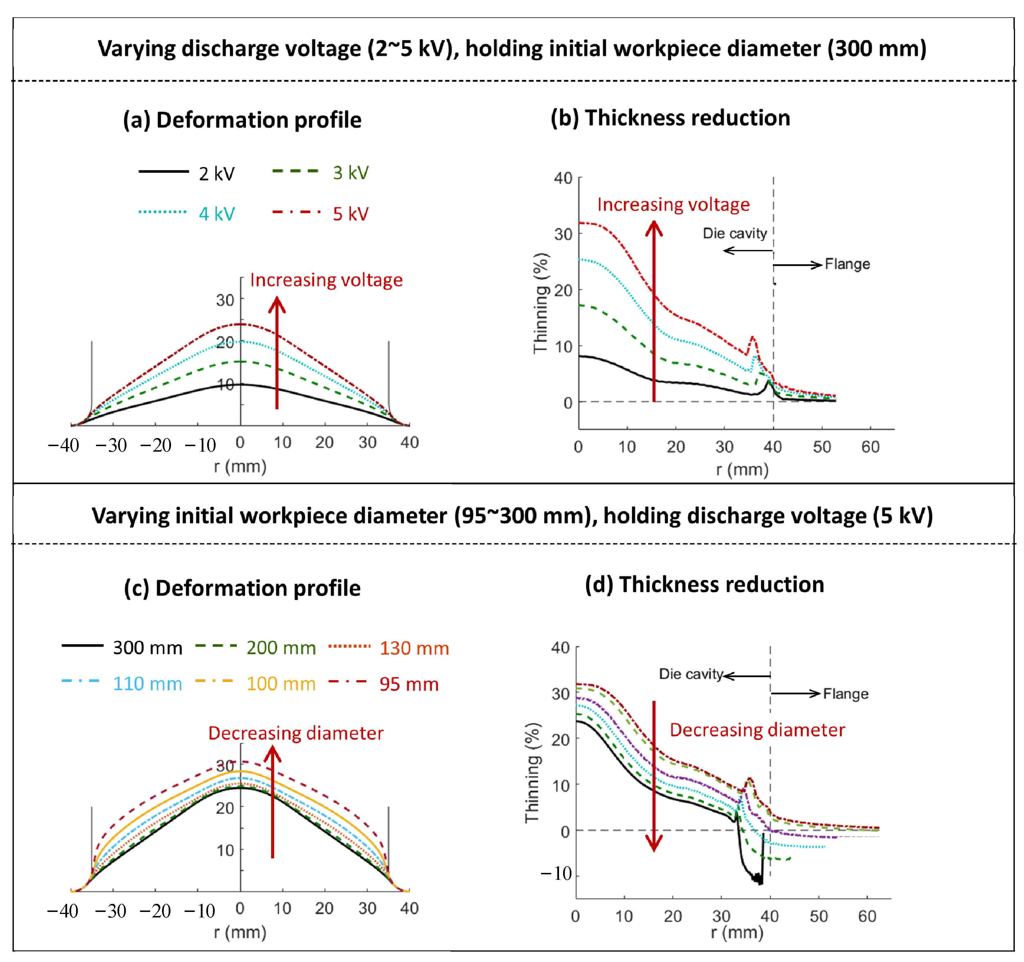
  • Adjusting the initial workpiece diameter could effectively alter the deformation behavior of the workpiece during the EMF process, by controlling the draw-in material flow of the sheet flange. More specifically, decreasing the initial workpiece diameter can exponentially enhance the draw-in, which helps to increase the forming height (~40%), relieve the thickness reduction (~27%), and assist in the formation of a perpendicular side-wall at the die corner.
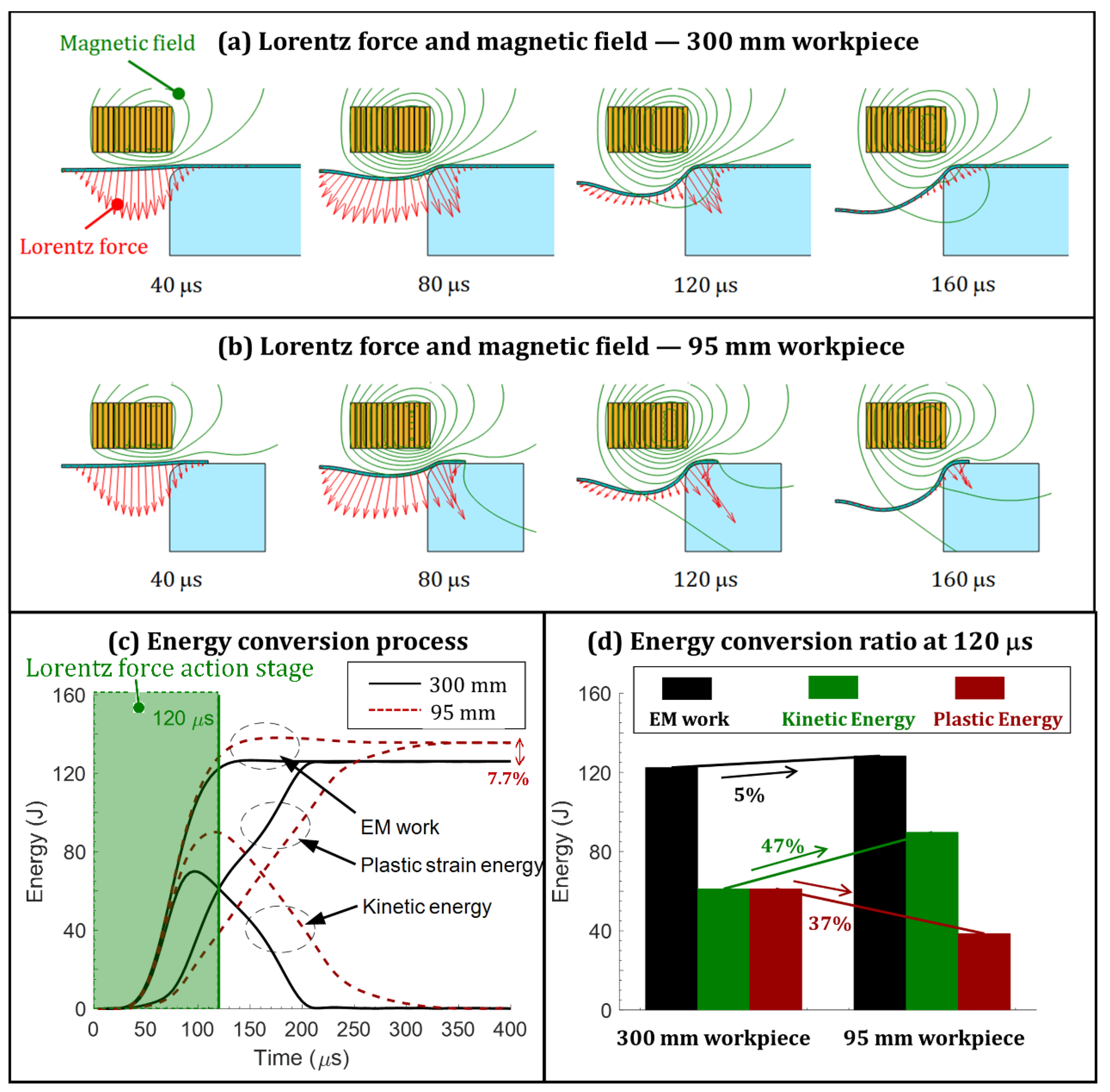
  • According to the loading feature, the whole forming process can be divided into the Lorentz force action stage and the inertia-force-dominated stage. The majority of the deformation changes under varied initial workpiece diameters occur at the inertia-force-dominated stage. This is because the draw-in is limited at the Lorentz force action stage, while it is substantially accumulated at the latter inertia-force-dominated stage. The accumulated draw-in in the inertia stage feeds substantial flange metal into the die cavity, relieving the deformation severity and changing the forming shape.
  • In summary, this study clearly demonstrates that the initial workpiece diameter could be an effective process parameter for deformation control in EMF. Introducing this design freedom could improve the controllability of the high-velocity deformation process, which helps to extend the available forming shape in EMF, thus opening avenues to new EMF applications.

Author Contributions

Methodology, J.W.; Validation, H.X.; Formal analysis, C.Z.; Investigation, W.Y.; Data curation, Z.W.; Writing—review & editing, M.C. All authors have read and agreed to the published version of the manuscript.

Funding

This research received no external funding.

Data Availability Statement

Data are contained within the article.

Conflicts of Interest

The authors declare no conflict of interest.

References

  1. Yang, D.Y.; Bambach, M.; Cao, J.; Duflou, J.R.; Groche, P.; Kuboki, T.; Sterzing, A.; Tekkaya, A.E.; Lee, C.W. Flexibility in metal forming. CIRP Ann. 2018, 67, 743–765. [Google Scholar] [CrossRef]
  2. Mamalis, A.G.; Manolakos, D.E.; Kladas, A.G.; Koumoutsos, A.K. Electromagnetic forming and powder processing: Trends and developments. Appl. Mech. Rev. 2004, 57, 299–324. [Google Scholar] [CrossRef]
  3. Daehn, G.S. High Velocity Metal Forming. In ASM Handbook, Metalworking: Sheet Forming; ASM International: Almere, The Netherlands, 2006; Volume 14B, pp. 405–418. [Google Scholar]
  4. Psyk, V.; Risch, D.; Kinsey, B.L.; Tekkaya, A.E.; Kleiner, M. Electromagnetic forming—A review. J. Mater. Process. Technol. 2011, 211, 787–829. [Google Scholar] [CrossRef]
  5. Kapil, A.; Sharma, A. Magnetic pulse welding: An efficient and environmentally friendly multi-material joining technique. J. Clean. Prod. 2015, 100, 35–58. [Google Scholar] [CrossRef]
  6. Kamal, M.; Daehn, G.S. A Uniform Pressure Electromagnetic Actuator for Forming Flat Sheets. J. Manuf. Sci. Eng. 2007, 129, 369–379. [Google Scholar] [CrossRef]
  7. Lai, Z.; Cao, Q.; Han, X.; Liu, N.; Li, X.; Huang, Y.; Chen, M.; Cai, H.; Wang, G.; Liu, L.; et al. A comprehensive electromagnetic forming approach for large sheet metal forming. Procedia Eng. 2017, 207, 54–59. [Google Scholar] [CrossRef]
  8. Vanbenthysen, R.; Thibaudeau, E.; Kinsey, B.L. Effect of specimen planar area on electromagnetic flanging. J. Manuf. Process. 2013, 15, 194–200. [Google Scholar] [CrossRef]
  9. Imbert, J.; Worswick, M. Reduction of a pre-formed radius in aluminium sheet using electromagnetic and conventional forming. J. Mater. Process. Technol. 2012, 212, 1963–1972. [Google Scholar] [CrossRef]
  10. Cao, Q.; Du, L.; Li, Z.; Lai, Z.; Li, Z.; Chen, M.; Li, X.; Xu, S.; Chen, Q.; Han, X.; et al. Investigation of the Lorentz-force-driven sheet metal stamping process for cylindrical cup forming. J. Mater. Process. Technol. 2019, 271, 532–541. [Google Scholar] [CrossRef]
  11. Iriondo, E.; Alcaraz, J.L.; Daehn, G.S.; Gutiérrez, M.A.; Jimbert, P. Shape calibration of high strength metal sheets by electromagnetic forming. J. Manuf. Process. 2013, 15, 183–193. [Google Scholar] [CrossRef]
  12. Woodward, S.; Weddeling, C.; Daehn, G.; Psyk, V.; Carson, B.; Tekkaya, A.E. Production of low-volume aviation components using disposable electromagnetic actuators. J. Mater. Process. Technol. 2011, 211, 886–895. [Google Scholar] [CrossRef]
  13. Qiu, L.; Yu, Y.; Xiong, Q.; Deng, C.; Cao, Q.; Han, X.; Li, L. Analysis of Electromagnetic Force and Deformation Behavior in Electromagnetic Tube Expansion with Concave Coil Based on Finite Element Method. IEEE Trans. Appl. Supercond. 2018, 28, 0600705. [Google Scholar] [CrossRef]
  14. Zhang, Z.; Lai, Z.; Li, C.; Zheng, Y.; Xu, W.; Wang, Z.; Li, M.; Gao, Y.; Cao, Q.; Han, X.; et al. Production and use of adaptive pulsed Lorentz force for multi-step electromagnetic sheet metal forming: Method, experimental validation, and application. Int. J. Adv. Manuf. Technol. 2022, 120, 5521–5536. [Google Scholar] [CrossRef]
  15. Zhang, Z.; Lai, Z.; Li, C.; Xu, W.; Hu, Y.; Li, X.; Cao, Q.; Han, X.; Li, L. A novel actuator for precise design of the spatial-distributed Lorentz force in electromagnetic sheet metal forming: Process principle, optimization methodology, and experimental validation. Int. J. Adv. Manuf. Technol. 2024, 131, 4425–4445. [Google Scholar] [CrossRef]
  16. Li, M.; Lai, Z.; Xu, W.; Zheng, Y.; Zhang, Z.; Li, C.; Gao, Y.; Wang, Z.; Cao, Q.; Han, X.; et al. A versatile electromagnetic actuator for sheet and tube flanging: Process principle, simulation, and experimental validation. J. Manuf. Process. 2022, 81, 311–327. [Google Scholar] [CrossRef]
  17. Yu, H.; Tong, Y. Magnetic pulse welding of aluminum to steel using uniform pressure electromagnetic actuator. Int. J. Adv. Manuf. Technol. 2017, 91, 2257–2265. [Google Scholar] [CrossRef]
  18. Weddeling, C.; Hahn, M.; Daehn, G.S.; Tekkaya, A.E. Uniform Pressure Electromagnetic Actuator—An Innovative Tool for Magnetic Pulse Welding. Procedia CIRP 2014, 18, 156–161. [Google Scholar] [CrossRef]
  19. Zhang, Y.; Babu, S.S.; Prothe, C.; Blakely, M.; Kwasegroch, J.; LaHa, M.; Daehn, G.S. Application of high velocity impact welding at varied different length scales. J. Mater. Process. Technol. 2011, 211, 944–952. [Google Scholar] [CrossRef]
  20. Raoelison, R.N.; Buiron, N.; Rachik, M.; Haye, D.; Franz, G. Efficient welding conditions in magnetic pulse welding process. J. Manuf. Process. 2012, 14, 372–377. [Google Scholar] [CrossRef]
  21. Lai, Z.; Cao, Q.; Zhang, B.; Han, X.; Zhou, Z.; Xiong, Q.; Zhang, X.; Chen, Q.; Li, L. Radial Lorentz force augmented deep drawing for large drawing ratio using a novel dual-coil electromagnetic forming system. J. Mater. Process. Technol. 2015, 222, 13–20. [Google Scholar] [CrossRef]
  22. Takatsu, N.; Kato, M.; Sato, K.; Tobe, T. High-speed forming of metal sheets by electromagnetic force. Jpn. Soc. Mech. Eng. Int. J. Ser. III 1988, 31, 142–148. [Google Scholar] [CrossRef]
  23. Imbert, J.M.; Winkler, S.L.; Worswick, M.J.; Oliveira, D.A.; Golovashchenko, S. The Effect of Tool–Sheet Interaction on Damage Evolution in Electromagnetic Forming of Aluminum Alloy Sheet. J. Eng. Mater. Technol. 2005, 127, 145. [Google Scholar] [CrossRef]
  24. Risch, D.; Beerwald, C.; Brosius, A.; Kleiner, M. On the significance of the die design for electromagnetic sheet metal forming. In Proceedings of the 1st International Conference on High Speed Forming—ICHSF, Dortmund, Germany, 31 March–1 April 2004; pp. 191–200. [Google Scholar]
  25. Noh, H.-G.; Song, W.-J.; Kang, B.-S.; Kim, J. Numerical and experimental approach to reduce bouncing effect in electromagnetic forming process using cushion plate. J. Mech. Sci. Technol. 2014, 28, 3263–3271. [Google Scholar] [CrossRef]
  26. Yu, H.; Chen, J.; Liu, W.; Yin, H.; Li, C. Electromagnetic forming of aluminum circular tubes into square tubes: Experiment and numerical simulation. J. Manuf. Process. 2018, 31, 613–623. [Google Scholar] [CrossRef]
  27. Ahmed, M.; Panthi, S.K.; Ramakrishnan, N.; Jha, A.K.; Yegneswaran, A.H.; Dasgupta, R.; Ahmed, S. Alternative flat coil design for electromagnetic forming using FEM. Trans. Nonferrous Met. Soc. China 2011, 21, 618–625. [Google Scholar] [CrossRef]
  28. Lai, Z.; Cao, Q.; Han, X.; Li, L. Analytical optimization on geometry of uniform pressure coil in electromagnetic forming and welding. Int. J. Adv. Manuf. Technol. 2019, 104, 3137. [Google Scholar] [CrossRef]
  29. Lai, Z.; Cao, Q.; Han, X.; Chen, M.; Liu, N.; Li, X.; Cao, Q.; Huang, Y.; Chen, Q.; Li, L. Insight into analytical modeling of electromagnetic forming. Int. J. Adv. Manuf. Technol. 2019, 101, 2585–2607. [Google Scholar] [CrossRef]
  30. Kamal, M.; Shang, J.; Cheng, V.; Hatkevich, S.; Daehn, G.S. Agile manufacturing of a micro-embossed case by a two-step electromagnetic forming process. J. Mater. Process. Technol. 2007, 190, 41–50. [Google Scholar] [CrossRef]
  31. Hu, J.; Marciniak, Z.; Duncan, J. Mechanics of Sheet Metal Forming, in High Velocity Forming; Elsevier: Amsterdam, The Netherlands, 2002. [Google Scholar]
  32. Golovashchenko, S. Electromagnetic forming and joining for automotive applications. In Proceedings of the 2nd International Conference on High Speed Forming—ICHSF, Dortmund, Germany, 20–21 March 2006; pp. 201–206. [Google Scholar]
  33. El-Azab, A.; Garnich, M.; Kapoor, A. Modeling of the electromagnetic forming of sheet metals: State-of-the-art and future needs. J. Mater. Process. Technol. 2003, 142, 744–754. [Google Scholar] [CrossRef]
  34. Lai, Z.; Cao, Q.; Han, X.; Huang, Y.; Deng, F.; Chen, Q.; Li, L. Investigation on plastic deformation behavior of sheet workpiece during radial Lorentz force augmented deep drawing process. J. Mater. Process. Technol. 2017, 245, 193–206. [Google Scholar] [CrossRef]
  35. Chen, M.; Lai, Z.; Cao, Q.; Han, X.; Liu, N.; Li, X.; Huang, Y.; Li, L. Investigation on deformation control of sheet metal in radial Lorentz force augmented deep drawing. Int. J. Adv. Manuf. Technol. 2019, 105, 2369–2381. [Google Scholar] [CrossRef]
  36. Lai, Z.; Cao, Q.; Chen, M.; Liu, N.; Li, X.; Huang, Y.; Han, X.; Li, L. The effect of coil polarity on electromagnetic forming using a multi-coil system. Int. J. Adv. Manuf. Technol. 2019, 103, 1555–1566. [Google Scholar] [CrossRef]
  37. Liu, N.; Lai, Z.; Cao, Q.; Han, X.; Huang, Y.; Li, X.; Chen, M.; Li, L. A comparative study on the effects of boundary constraints on electromagnetic sheet forming. Int. J. Adv. Manuf. Technol. 2019, 101, 2785–2793. [Google Scholar] [CrossRef]
  38. Chen, M.; Lai, Z.; Cao, Q.; Han, X.; Wang, C.; Liu, N.; Li, L. Improvement on formability and forming accuracy in electromagnetic forming of deep-cavity sheet metal part using a dual-coil system. J. Manuf. Process. 2020, 57, 209–221. [Google Scholar] [CrossRef]
  39. Cao, Q.; Li, Z.; Lai, Z.; Li, Z.; Han, X.; Li, L. Analysis of the effect of an electrically conductive die on electromagnetic sheet metal forming process using the finite element-circuit coupled method. Int. J. Adv. Manuf. Technol. 2019, 101, 549–563. [Google Scholar] [CrossRef]
  40. Yu, H.; Li, C.; Deng, J. Sequential coupling simulation for electromagnetic–mechanical tube compression by finite element analysis. J. Mater. Process. Technol. 2009, 209, 707–713. [Google Scholar]
Figure 1. Experimental setup.
Electronics 13 03828 g001
Figure 2. Dependences of draw-in on (a) discharge voltage and (b) workpiece diameter. Herein, the draw-in is defined as the radial inward displacement at the sheet periphery.
Electronics 13 03828 g002
Figure 3. Dependences of forming height on (a) discharge voltage and (b) workpiece diameter.
Electronics 13 03828 g003
Figure 4. (a) Deformation profile and (b) thickness reduction distribution under varied discharge voltages (2–5 kV), with an initial workpiece diameter of 300 mm; (c) deformation profile and (d) thickness reduction distribution under varied initial workpiece diameters (95–300 mm), with a discharge voltage of 5 kV.
Electronics 13 03828 g004
Figure 5. Dynamic loading process for two workpieces (∅300 mm and ∅95 mm workpieces). The discharge voltage is maintained at 5 kV.
Electronics 13 03828 g005
Figure 6. Evolution of deformation profiles for two workpieces (300 mm and 95 mm) while the discharge voltage is maintained at 5 kV.
Electronics 13 03828 g006
Figure 7. Deformation control by adjusting the discharge voltage and the initial workpiece diameter.
Electronics 13 03828 g007
Table 1. System parameters.
ComponentParameterValue
Discharge circuitCapacitance320 μF
Machine inductance10 μH
Machine resistance25 mΩ
WorkpieceElectrical resistivity2.65 × 10−8 Ω·m
Permeability4π × 10−7 H/m
Mass density2.7 × 103 kg/m3
Young modulus70 GPa
Poisson ratio0.34
Contact interfaceFriction coefficient (Coulomb friction law)0.15
Copper conductorElectrical resistivity1.75 × 10−8 Ω·m
Permeability4π × 10−7 H/m
Mass density8.9 × 103 kg/m3
Young modulus110 GPa
Poisson ratio0.34
Initial yield stress135 MPa
Tangent modulus0.4 GPa
Zylon fiberMass density1.56 × 103 kg/m3
Young modulus (r/θ/z)3/230/3 GPa
Poisson ratio (rz/rθ/zθ)0.34/0.0148/0.0148
Epoxy resin boardMass density2.6 × 103 kg/m3
Young modulus22 GPa
Poisson ratio0.34
DieMass density7.9 × 103 kg/m3
Young modulus180 GPa
Poisson ratio0.34
Table 2. Process parameters for experimental and numerical investigations.
Voltage/kVDiameter/mmDrawing Ratio
Experiment2, 3, 4, 595, 100, 110, 1301.36, 1.43, 1.57, 1.86
Simulation2, 3, 4, 595, 100, 110, 130,
150, 200, 300
1.36, 1.43, 1.57, 1.86,
2.14, 2.86, 4.29
Disclaimer/Publisher’s Note: The statements, opinions and data contained in all publications are solely those of the individual author(s) and contributor(s) and not of MDPI and/or the editor(s). MDPI and/or the editor(s) disclaim responsibility for any injury to people or property resulting from any ideas, methods, instructions or products referred to in the content.

