Article

Simulation-Based Hybrid Energy Storage Composite-Target Planning with Power Quality Improvements for Integrated Energy Systems in Large-Building Microgrids

1
State Grid Hebei Economic Research Institute, No. 27 Fuqiang Street, Yuhua District, Shijiazhuang 050081, China
2
The School of Electrical Engineering, Xi’an Jiaotong University, Xi’an 710049, China
3
State Grid Handan Electric Power Supply Company, Handan 056000, China
*
Author to whom correspondence should be addressed.
Electronics 2024, 13(19), 3844; https://doi.org/10.3390/electronics13193844 (registering DOI)
Submission received: 29 July 2024 / Revised: 19 September 2024 / Accepted: 26 September 2024 / Published: 28 September 2024
(This article belongs to the Special Issue Innovations in Intelligent Microgrid Operation and Control)

Abstract

:
In this paper, we present an optimization planning method for enhancing power quality in integrated energy systems in large-building microgrids by adjusting the sizing and deployment of hybrid energy storage systems. These integrated energy systems incorporate wind and solar power, natural gas supply, and interactions with electric vehicles and the main power grid. In the optimization planning method developed, the objectives of cost-effective and low-carbon operation, the lifecycle cost of hybrid energy storage, power quality improvements, and renewable energy utilization are targeted and coordinated by using utility fusion theory. Our planning method addresses multiple energy forms—cooling, heating, electricity, natural gas, and renewable energies—which are integrated through a combined cooling, heating, and power system and a natural gas turbine. The hybrid energy storage system incorporates batteries and compressed-air energy storage systems to handle fast and slow variations in power demand, respectively. A sensitivity matrix between the output power of the energy sources and the voltage is modeled by using the power flow method in DistFlow, reflecting the improvements in power quality and the respective constraints. The method proposed is validated by simulating various typical scenarios on the modified IEEE 13-node distribution network topology. The novelty of this paper lies in its focus on the application of integrated energy systems within large buildings and its approach to hybrid energy storage system planning in multiple dimensions, including making co-location and capacity sizing decisions. Other innovative aspects include the coordination of hybrid energy storage combinations, simultaneous siting and sizing decisions, lifecycle cost calculations, and optimization for power quality enhancement. As part of these design considerations, microgrid-related technologies are integrated with cutting-edge nearly zero-energy building designs, representing a pioneering attempt within this field. Our results indicate that this multi-objective, multi-dimensional, utility fusion-based optimization method for hybrid energy storage significantly enhances the economic efficiency and quality of the operation of integrated energy systems in large-building microgrids in building-level energy distribution planning.

1. Introduction

In recent years, integrated energy systems (IESs) have emerged as efficient energy supply models combining multiple forms of energy, such as cooling, heating, electricity, and gas, for unified planning and dispatch [1,2,3]. Incorporating this kind of design into the building sector, which involves major energy consumption, can facilitate the creation of nearly zero-energy buildings and support the transition to new power systems [4,5,6]. In this context, combined cooling, heating, and power (CCHP) systems with microgrids extend the energy supply capabilities of traditional microgrids. This integration not only fuses the functions of cooling, heating, and providing electricity but also promotes the full utilization of renewable energy sources [7,8]. However, several challenges are encountered in planning IESs in large buildings, including conflicts in system operation efficiency, the impact of uncertainties, high peak-load supply pressure, and the low absorption rates of wind and solar energy [9]. Numerous studies have proven that well-designed energy storage systems can act as buffers in ensuring efficient and stable system operation, making hybrid energy storage planning a crucial element for the stable, eco-friendly, and cost-effective development of IESs in microgrids for large buildings [10,11,12,13,14].
IES planning has been optimized widely in research, namely, by constructing multi-dimensional optimization objectives to evaluate that each aligns with the characteristics of the system models [15]. While some studies have considered multiple types of economic costs, such as operation and maintenance costs, equipment construction costs, and energy transaction costs [16,17,18,19], other studies have begun to consider their optimization objectives from multiple perspectives. These include minimizing the investment and operational costs, maximizing efficiency, and reducing carbon emissions under various uncertainties [20]. In some approaches, planning is modeled as a deterministic bi-objective optimization problem in which the investment and operational costs are targeted alongside robustness [21]. For integrated energy systems equipped with carbon capture, optimization models focus on minimizing the investment costs, energy purchase costs, energy sales revenue, and carbon costs [22]. In coordinating integrated energy system planning and designing capacity allocation schemes for scenarios involving high renewable energy penetration, both environmental penalties and subsidies for generating renewable energy are accounted for in the operational costs [23]. Another model proposed for a regional integrated energy system, which includes electric, thermal, and cooling buses, has also considered cost-effective and low-carbon operation of the system [24]. On the basis of these studies, it is evident that in addition to economic goals, multiple dimensions, including carbon emissions and system robustness, have been considered in research in order to meet the requirements of various scenarios.
Energy storage devices play the key bridging role of energy hubs in integrated energy systems. Indeed, researchers have utilized various types of energy storage systems to smooth the output power of stochastically volatile renewable energy systems, such as those incorporating wind and solar power [25,26], as well as to harmonize and compensate for fluctuating changes in customer loads, thereby improving their operational efficiency [27]. It has been demonstrated that introducing an optimal energy storage model into an integrated energy system can also enhance its operational flexibility [28]. Additionally, in simulating and comparing wind turbines with and without energy storage, the inclusion of energy storage was verified as an effective improvement in the efficiency of renewable energy utilization [29]. Thus, planning energy storage systems in designing IESs has been the subject of substantial research attention. Considering objectives such as battery lifespan degradation, minimizing the annual operational and storage investment costs, and economic efficiency, studies have explored how to optimize regional integrated energy systems (RIESs) by using hybrid battery/pumped storage, multi-energy storage systems in IESs, and hybrid energy storage planning [30,31,32]. Some research has also focused on a joint planning model for integrated energy systems with shared storage, aiming to plan the optimal construction timeline for storage equipment based on the total investment and operational costs [33]. However, despite these contributions, most of the existing studies on planning energy storage in IESs have focused primarily on the construction costs, the lifespan of the centralized storage systems, and the economic benefits to system operation while often overlooking the design of distributed hybrid energy storage systems at the operational level. Choosing the optimal siting can further enhance system performance, improve power quality, and increase the flexibility and safety of the configuration. With the current policy developments, higher renewable energy integration can also yield additional benefits, such as securing government subsidies and “green power certificates”. Therefore, renewable energy utilization rates should be considered part of the optimization objectives. However, existing research on microgrid IEEs for large buildings has not fully leveraged the advantages of storing energy by using distributed siting and hybrid configurations to promote high-quality operation and renewable energy utilization, and such limitations have hindered the potential of energy storage systems in this context.
Motivated by the aforementioned studies, this paper uses a linearized DistFlow model to examine the underlying grid configuration and operational constraints of an IES for a large-building microgrid. Multiple optimization objectives are incorporated, including its cost-effective and low-carbon operation, lifecycle construction costs, system power quality improvements, and renewable energy absorption. By integrating these factors with utility fusion theory, we achieve optimal hybrid energy storage planning for IESs in large-building microgrids, ensuring low-carbon, cost-effective, and efficient renewable energy utilization while maintaining optimized system operation.
The salient features of this study are as follows:
  • This study establishes a DistFlow power flow model of an IES for a large-building microgrid, improving power quality by considering the sensitivity of the node voltages and power injected into the microgrid. It also incorporates renewable energy, CCHP, electric vehicle charging interactions, and hybrid energy storage systems, facilitating the optimization of IESs that make use of multiple energy sources.
  • The planning method proposed addresses how to manage fast and slow variations in power demand for hybrid energy storage on the basis of multi-cycle variations in power. This comprehensive model lays the foundation for optimizing the location and capacity of hybrid energy storage planned in IESs in large-building microgrids.
  • Considering multiple dimensions beyond economic and low-carbon factors, including power quality optimization, new energy consumption, and the lifecycle cost of hybrid energy storage systems, this study coordinates all of these different aspects by using utility fusion theory, resulting in comprehensive and reliable planning under various scenarios.
The remainder of the paper organized as follows: Section 2 establishes the underlying model of the IES in a large-building microgrid. In Section 3, we design the multi-dimensional optimization objectives and formulate the operational constraints of the IES in a large-building microgrid. In Section 4, we demonstrate the effectiveness and performance of the planning model based on case studies. Section 5 discusses and summarizes the research content and value of this study. For the reader’s convenience, Table A1 and Table A2 list the variable and parameter symbols used in this paper, respectively.

2. Analysis of Integrated Energy Systems in Building Microgrids

2.1. Mathematical Models of Integrated Energy Systems in Large Buildings

Figure 1 illustrates the IES used in large-building microgrids discussed in this paper. To fully explore the potential of large buildings to accommodate renewable energy and the development of new power systems, this system takes into account the impact of wind and solar power generation. Additionally, this system features multi-energy complementarity, allowing users to switch between energy sources flexibly based on the electricity pricing at the time of use, facilitating a comprehensive response to demand [34]. Moreover, the system accounts for how charging stations in buildings can optimize the charging process to improve the energy supply–demand balance while still meeting users’ needs. However, due to the uncertainty of electric vehicle charging and its limited scale, this aspect has a limited impact on energy systems involving numerous energy devices and complex operations. Therefore, the IES is configured with a more flexible and reliable hybrid energy storage system to accommodate fluctuations in the renewable energy output and load. The optimization planning of hybrid energy storage is at the core of designing an cost-effective, high-quality, operational IES for a large building. Specifically, the CCHP system established consists of electric chillers, electric heaters, microturbines, natural gas boilers, and lithium bromide absorption chillers. The microturbines simultaneously provide both electricity and heat. Meanwhile, the energy storage system, in combination with the electric heating and cooling units, meets the power, heating, and cooling demands of the IES by storing excess electricity during periods of low demand and releasing it with peak demand, thereby smoothing any demand spikes. The natural gas boilers can provide supplementary heating when electric heating is not feasible, and the absorption chillers can utilize any excess heat for cooling. By linking these components through a distribution network power flow model, the CCHP system achieves the gradient utilization of energy and the coordinated complementation of various energy forms.

2.1.1. The Microturbine

The relationship between the heat generated by the microturbine and its electrical output power is [23]
q i , n MT ( t ) = p i , n MT ( t ) 1 η e MT η l MT η e MT
where q i , n MT is its exhaust heat at node i at time t in the nth scenario; p i , n MT is its electrical output power at node i at time t in the nth scenario; η e MT is its electrical efficiency, set to 0.3; and η l MT is its heat loss coefficient, set to 2%.
The natural gas consumed by the microturbine can be expressed as
v i , n MT ( t ) = p i , n MT ( t ) q i , n MT L ng
where v i , n MT is the amount of natural gas consumed by the microturbine per unit time; L ng is the lower heating value of natural gas, set to 9.78 (kW·h)/m3; and Δ T is the length of the time step.

2.1.2. The Natural Gas Boiler

The heat generated by the natural gas boiler is [2]
q i , n BLR ( t ) = n h L ng v i , n BLR ( t )
where q i , n BLR is the heat output of the natural gas boiler, n h is the boiler’s efficiency, and v i , n BLR is the natural gas consumption of the boiler per unit time.

2.1.3. The Electric Heater

The heat generated by the electric heater is
q i , n EH ( t ) = C op EH p i , n EH ( t )
where q i , n EH is the heat output of the electric heater, C op EH is its coefficient of performance (COP), and p i , n EH is its electrical power consumption.

2.1.4. The Electric Chiller

The cooling capacity of the electric chiller is
r i , n EC ( t ) = C op EC p i , n EC ( t )
where r i , n EC is the cooling capacity of the electric chiller, C op EC is its COP, and p i , n EC is its electrical power consumption.

2.1.5. The Absorption Chiller

Using heat to drive the cooling cycle, the cooling capacity of the absorption chiller is [2]
r i , n ACH ( t ) = C op ACH q i , n ACH ( t )
where r i , n ACH is the cooling output of the absorption chiller; C op ACH is its COP, set to 1.38; and q i , n ACH is its heat input at time t.

2.1.6. Hybrid Energy Storage

With the aim of achieving energy supply–demand balance and voltage support, this paper incorporates designing the parameters of hybrid energy storage devices into decision making for the optimization of IESs in microgrids for large buildings. By considering the characteristics of different energy storage technologies, these systems can be tailored to meet diverse needs [35,36]. Battery energy storage systems (BESSs) offer high flexibility and fast responses to energy or load fluctuations. In contrast, compressed-air energy storage (CAES) systems feature long lifespans, low loss, and low self-discharge rates but slower response times, making them suited to energy peak shifting. Therefore, this paper proposes a hybrid energy storage system that combines batteries and CAES for better adaptation to IESs in large-building microgrids, enhancing the flexibility of their design and economic efficiency. In terms of the differences in the charge–discharge response speed, power, and capacity costs between the two, CAES systems have a longer power update cycle, making them well equipped to handle shifts in renewable energy peaks and real-time electricity price utilization. Conversely, batteries require faster power update rates to absorb the volatility of renewable energy systems and the randomness of their short-term output. Currently, industrial facilities with high and fluctuating energy demands are among the types of buildings suited to installing CAES systems, where CAES can be used to balance their energy consumption. Additionally, large commercial buildings and data centers with sufficient space and continuous energy needs may also consider the use of CAES for backup power and load balancing, while remote or isolated facilities with limited grid access can use CAES as a long-term energy storage solution.
Batteries typically have a higher energy conversion efficiency and smaller discharge depth compared with CAES. On the other hand, CAES systems generally have lower energy conversion efficiency but can achieve larger charge–discharge depth. Therefore, when designing a hybrid energy storage system, it is essential to consider efficiency during the charge–discharge processes to ensure the corresponding energy-level calculations are accurate. The specific model of the energy storage system is built as follows [8]:
p i , n cCAES ( T CAES l ) = p i , n cCAES ( T CAES l + T BATT ) = = p i , n cCAES ( T CAES l + ( N T 1 ) T BATT ) p i , n dCAES ( n N T T BATT ) = p i , n dCAES ( n N T T BATT + T BATT ) = = p i , n dCAES ( n N T T BATT + ( N T 1 ) T BATT ) e i , n CAES ( t ) = E i , n CAES 0 + s = 1 t Δ T n c CAES p i , n cCAES ( s ) p i , n dCAES ( s ) p i , n dCAES ( s ) n d CAES n d CAES e i , n BATT ( t ) = E i , n BATT 0 + s = 1 t Δ T n c BATT p i , n cBATT ( s ) p i , n dBATT ( s ) p i , n dBATT ( s ) n d BATT n d BATT
where T BATT is the power variation cycle of the BESS; T CAES l is the lth power variation cycle of the CAES system, ranging from 0 to T / N T 1 ; N T is the ratio of the power variation cycle of the CAES system to that of the BESS; p i , n dCAES is the discharge power of the CAES system; p i , n dBATT is the discharge power of the BESS; p i , n cCAES is the charge power of the CAES system; p i , n cBATT is the charge power of the BESS; e i , n CAES is the remaining energy of the CAES system; E i , n CAES 0 is the initial energy of the CAES system; n c CAES and n d CAES are the charging and discharging efficiency of the CAES system; e i , n BATT is the remaining energy of the BESS; E i , n BATT 0 is the initial energy of the BESS; and n c BATT and n d BATT are the charging and discharging efficiency of the BESS.

2.1.7. Electric Vehicle Charging Stations

Just as hybrid energy storage systems have a buffering effect on the electricity supply, EVs provide a limited response to demand. We modeled user charging behavior by utilizing variables such as user access to charging stations, the expected charging time, and the target battery level and integrated it into the model, prioritizing the need for electric vehicles to reach the user’s expected battery level by the projected charging completion time. During the vehicle charging process, the charging load can be dynamically adjusted based on the real-time energy supply and demand, ensuring that the building’s core load requirements are not compromised.
e i , n EV ( t ) = E i , n EV 0 + s = 1 t Δ T n c EVCS p i , n cEVCS ( s ) p i , n dEVCS ( s ) p i , n dEVCS ( s ) n d EVCS n d EVCS
where p i , n cEVCS is the charging power provided by the charging station to the electric vehicle, p i , n dEVCS is the discharging power drawn from the electric vehicle by the charging station, e i , n EV is the remaining energy (state of charge) of the electric vehicle, E i , n EV 0 is the initial energy (initial state of charge) of the electric vehicle, and n c EVCS and n d EVCS are the charging and discharging efficiency of the EV charging station.

2.2. The DistFlow Power Flow Model for an IES in a Large-Building Microgrid

Once the hybrid energy storage system is integrated, the system is able to balance electricity purchases from the main grid with the renewable energy output to meet the load demands and improve voltage quality. Basic power flow constraints, such as the power balance at each node and the voltage limits at each node, must be adhered to considering the formation of the underlying distribution network. The DistFlow model is adopted as the power flow model for the microgrid. For computational convenience, the DistFlow model is linearly approximated to establish the operating constraints of the underlying distribution network, and then a power flow model of this network is established.
Let P i , n and Q i , n represent the active and reactive power flows into node i in the underlying distribution network. Given that the underlying distribution network has a tree topology with the distributed generation located at the root node, each node has only one incoming power flow. The active power and reactive power balance at each node in the underlying distribution network can be written as
j S i P j , n = P i , n + p i , n , i N j S i Q j , n = Q i , n + q i , n , i N
where S i denotes the set of child nodes for grid node i; P j , n and Q j , n are the active and reactive power flows from node i to node j in the nth scenario; p i , n and q i , n denotes the injected power of all the devices accessing node i in the nth scenario, including the contributions from the grid, photovoltaic systems, wind power systems, energy storage systems, and electrical loads; and N denotes the set of all the nodes in the microgrid. p i , n and q i , n are in the following form:
p i , n = p i , n GP ( t ) + p i , n MT ( t ) + p i , n PV ( t ) + p i , n WTG ( t ) + p i , n dCAES ( t ) + p i , n dBATT ( t ) + p i , n dEVCS ( t ) p i , n cCAES ( t ) p i , n cBATT ( t ) p i , n cEVCS ( t ) p i , n LOAD ( t ) p i , n EH ( t ) p i , n EC ( t )
where p i , n GP is the power purchased from the grid, p i , n PV is the output power from the photovoltaic system, p i , n WTG is the output power from the wind power system, and p i , n LOAD is the electrical load.
Considering the voltage constraints at the nodes in the system, the voltage at the grid connection node will be set as the reference value. According to the linearized DistFlow model, the voltage at the other nodes in the grid can be expressed as follows:
V i , n = V j , n r i P i , n + x i Q i , n V 0 , j = θ ( i ) , i N ¯
where V i , n is the voltage magnitude at node i in the nth scenario, θ ( i ) represents the previous node connected to node i, r i is the line resistance with node i as the endpoint, x i is the line reactance with node i as the endpoint, and V 0 is the reference voltage for the entire microgrid.

3. Configuration of Distributed Hybrid Energy Storage System’s Capacity and Its Operational Optimization

The variables for optimization include the hourly quantities of electricity and gas purchased for each day of the integrated energy system’s operation, the operational power values in each part of the hybrid energy storage system, and the design capacity and rated power of each energy storage device based on the operational conditions. The aim of the optimization process is to minimize the total lifecycle costs of the hybrid energy storage, including economic and low-carbon operational costs, while maintaining power quality. The constraints in the design take into account the linearized DistFlow power flow model for the underlying distribution network, the operational models of the cooling and heating equipment, the constraints on the output of the devices in the system, and the operational models of hybrid energy storage devices.

3.1. Optimization Objective Function for Distributed Multi-Energy Storage Configuration

The optimization objective for the hybrid energy storage configuration considers its cost-effective and low-carbon performance during system operation, reflecting the costs associated with purchasing external energy and the construction costs of the hybrid energy storage system over its entire lifecycle, including the initial costs of investing in the power of its design and its capacity and the cumulative costs of CAES over its lifespan. Finally, the power flow is calculated to tailor the optimization objective to voltage fluctuations, highlighting the support provided by the design of the energy storage in terms of the system voltage.

3.1.1. Economic Cost

The integrated energy system’s operational cost is based on the external purchase of electricity and natural gas, accounting for time-of-use pricing to maximize the utilization of its storage capacity and exploit peak–valley energy pricing. The optimization timeframe is based on the lifespan of CAES, summing up all daily operational events and then aggregating them across its entire lifecycle considering the frequency of specific scenarios occurring.
f Trans = n life n = 1 N S t = 1 T n n scen Δ T C P G V n G ( t ) + C P E ( t ) p n GP ( t )
where n life represents the designed usage time for the energy storage system, N S is the number of scenarios, T is the total number of time intervals, n n scen is the frequency of the nth scenario, Δ T is the time interval within each unit of time, C P G is the purchase cost per unit of natural gas, V n G is the consumption of natural gas per unit time, C P E is the time-of-use price of purchasing electricity from the grid, and p n GP is the quantity of electricity purchased from the grid per unit time.

3.1.2. Low-Carbon Cost

Carbon emission targets are part of operational cost optimization and are similar in form to economic cost. Carbon emissions from natural gas consumption and grid electricity generation are considered and then integrated with the carbon market trading price to unify the unit of measurement of the objective function.
f CO 2 e = n life n = 1 N S t = 1 T n n scen Δ T C P C m gas V n G ( t ) + m grid p n GP ( t )
where m gas is the carbon emission factor for natural gas and m grid is the carbon emission factor for the grid. These values are based on the carbon market trading prices.

3.1.3. Lifecycle Cost of Hybrid Energy Storage System

The lifecycle cost of energy storage encompasses all costs related to the energy storage system throughout its entire lifecycle, including its design and construction, maintenance and operation, and replacement and recycling. This comprehensive metric permits a more thorough evaluation of the system’s economic efficiency and sustainability. The objective function designed accounts for the initial construction costs and the annual operating and maintenance costs, as well as the costs of replacing and recycling equipment, based on the system’s lifespan, adjusted for the standard discount rate [26].
f ES = C E ES E set + C P ES P set + y = 1 Y C E OM E set + C P OM P set + C labor n labor + C C R E set + C Rec ( 1 + r ) y
where C E ES is the unit cost of storage capacity, E set is the installed capacity of the energy storage solution, C P ES is the unit cost of storage power, P set is the installed power of the energy storage solution, Y is the service life in years of the system design, C E OM is the maintenance cost per unit of energy storage capacity, C P OM is the maintenance cost per unit of power, C labor is the cost per person per year of maintenance personnel, n labor is the number of energy storage system operation and maintenance personnel, C C R is the cost of replacements per unit of energy storage capacity, C Rec is the cost of energy storage recovery, and r is the standard discount rate or the benchmark rate of return.
The cost of recovery is expressed as
C Rec = ( C E ES E set + C P ES P set ) × F EOL
where F EOL is the end-of-life cost ratio, which is the ratio of the recovery cost to the initial investment and can be positive or negative.

3.1.4. Minimizing Voltage Deviation

In this study, we incorporate modeling the power flow and making calculations for the underlying grid into the integrated energy system, allowing us to obtain the voltage values at various nodes. By considering the per-unit (pu) system, the absolute deviations in each node’s voltage from the standard reference voltage are summarized and then aggregated over multiple typical scenarios throughout the system’s entire operational period, resulting in an objective function that reflects the quality of the system’s power supply.
f Volt = n life n = 1 N S t = 1 T n n scen Δ T i = 1 N V i * ( t ) 1
where V i * is the normalized value of the voltage at node i.

3.1.5. Renewable Energy Utilization

We also consider the system’s actual ability to utilize renewable energy in this study. By calculating the difference between the renewable energy actually used by the system during its operation and the maximum amount of renewable energy theoretically able to be generated, we derive an objective function that reflects the system’s capacity to utilize renewable energy.
f Utilization = n life n = 1 N S t = 1 T n n scen Δ T P energy theory t P energy real t
where P energy real is the total new energy output power of the actual operation of the system, and P energy theory is the total maximum new energy output power that can theoretically be generated by the system.

3.1.6. The Composite Objective

The first three indicators proposed in this paper are unified into a cost function measured by price, while the fourth and fifth indicators used are operational voltage quality and renewable energy utilization. Given that these indicators reflect different types of utility and that there are conflicts and complementarities between them, based on utility fusion theory, we designed a utility function to characterize to what extent these various objectives are satisfied. This ultimately represents a comprehensive evaluation objective function that can be used to guide the optimization planning process. First, the three objective functions that have already been unified are combined:
f 1 = f Trans + f CO 2 e + f ES
And the fourth and fifth objective functions reflecting the system’s operational effectiveness indicators are
f 2 = f Volt f 3 = f Utilization
Since the three types of objectives in this study are all minimization optimization problems with differing units and magnitudes, the difference ratio is used as the basic utility function for the optimization objectives. In transforming each optimization metric into a dimensionless basic utility value within the range of 0 to 1, it can thereby normalize these metrics and eliminate the incommensurability between them. The difference ratio effectively reflects the discrepancy between the current value for each optimization metric and its theoretical optimal value.
F k = f k max f k f k max f k min
where F k is the underlying utility function for the kth objective, f k is the kth objective function, f k max is the theoretical maximum of the kth objective function, and f k min is the theoretical minimum of the kth objective function.
Considering the negative correlation between the objective of the minimum voltage deviation, reflective of the level of the system’s operational optimization, and the cost indicators for construction and operation, we use a distance function to combine it with these cost indicators. Additionally, the utility function designed is inversely proportional to the original objective function. Therefore, the final multi-dimensional utility integration objective function for the configuration of the hybrid energy storage system is formulated as a maximization problem:
min W = ω 1 F 1 + ω 2 F 2 + ω 3 F 3
where ω 1 , ω 2 , and ω 3 are the weights corresponding to each type of utility function.

3.2. Distributed Hybrid Energy Storage Configuration Optimization Constraints

3.2.1. Power Flow Operation Constraints

The voltage constraints for the node design specify the upper and lower bounds of voltage fluctuations:
V i , n lower V i , n V i , n upper , i N
where V i , n lower is the lower bound of the voltage magnitude at node i and V i , n upper is the upper bound of the voltage magnitude at node i.

3.2.2. Cold/Heat Load Demand Energy Balance Constraints

Ensuring a balance between the cooling and heating load requirements in buildings is crucial. Based on models of the electric chillers, electric heaters, micro gas turbines, gas boilers, and absorption chillers, a thermal load energy balance constraint is established for the system:
r i , n EC ( t ) + r i , n ACH ( t ) = r i , n load ( t ) q i , n MT ( t ) + q i , n BLR ( t ) + q i , n EH ( t ) = q i , n load ( t )
where r i , n load is the cooling load demand at node i in the nth scenario and q i , n load is the heating load demand at node i in the nth scenario.

3.2.3. Equipment Unit Output Constraints

Among the constraints on the output of various forms of equipment in the integrated energy system are the non-negative constraints on natural gas consumption and the operational output constraints on different energy supply devices, such as micro gas turbines, natural gas boilers, electric chillers, electric heaters, and absorption chillers. In the hybrid energy storage system, constraints on the charging and discharging power limits are also considered. To avoid energy being lost due to the energy storage simultaneously charging and discharging, for each energy storage device in the system, a binary variable U is introduced to indicate its operating state (charging or discharging), constrained between 0 and 1. Therefore, the overall equipment operation constraint can be expressed as
P min A P run U P max P run = P run EU P run ES T P run EU = q i , n BLR ( t ) p i , n GP ( t ) p i , n EC ( t ) p i , n EH ( t ) p i , n MT ( t ) r i , n ACH ( t ) P run ES = p i , n cCAES ( t ) p i , n dCAES ( t ) p i , n cBATT ( t ) p i , n dBATT ( t ) p i , n cEVCS ( t ) p i , n dEVCS ( t ) P min = 0 0 0 0 0 0 0 0 T P max = B G C H M R P i CAES P i CAES P i BATT P i BATT P i EVCS P i EVCS T U = I 6 × 6 0 0 0 0 0 U i , n cCAES ( t ) 0 0 0 0 0 U i , n dCAES ( t ) 0 0 0 0 0 U i , n cBATT ( t ) 0 0 0 0 0 U i , n dBATT ( t ) A = n h L ng 0 0 I 7 × 7
where P run is the set of operational state variables for each device in the system; A is the matrix of the system equipment’s operating parameters; U is the matrix of the 0–1 variables indicating the operating states of the hybrid energy storage devices; P min is the set of the lower limits of the output of each piece of equipment; P max is the set of the upper limits of the output of each piece of equipment; P run EU is the set of the operational state variables for the system’s energy supply-related equipment; P run ES is the set of the operational state variables for the system’s hybrid energy storage devices; P i CAES is the installed power of the CAES device designed; P i BATT is the installed power of the BESS device designed; B is the upper limit on the heat provided by the boiler; C is the upper limit on the electric chiller’s power; H is the upper limit on the electric heater’s power; G is the upper limit of power purchases per unit of time on the grid; M is the upper limit on the electrical power of the microturbine; R is the upper limit on the refrigeration power of the absorption chillers; U i , n cCAES is a 0–1 variable, which is the state of charge flag for the CAES system; U i , n dCAES is a 0–1 variable, which is the state of discharge flag for the CAES system; U i , n cBATT is a 0–1 variable, which is the state of charge flag for the BESS; and U i , n dBATT is a 0–1 variable, which is the discharge state flag for the BESS.
In order to avoid simultaneously discharging and charging an energy storage device and to impose constraints on the siting of the hybrid energy storage installation, constraints for charging and discharging the energy storage system that vary in sign are designed as follows:
U i , n cCAES ( t ) + U i , n dCAES ( t ) 1 U i , n cBATT ( t ) + U i , n dBATT ( t ) 1 U i , n cCAES ( t ) X i CAES U i , n dCAES ( t ) X i CAES U i , n cBATT ( t ) X i BATT U i , n dBATT ( t ) X i BATT
where X i CAES is a 0–1 flag variable for the siting of the CAES device indicating whether or not a CAES system is installed at the ith node, with this value equal to 1 if it is, and X i BATT is a flag variable for whether the ith node has battery storage installed or not.
The constraints on the siting flag variables are as follows:
X i CAES X i canset X i BATT X i canset i = 1 n X i CAES = N caes i = 1 n X i BATT = N batt
where X i canset is a flag for whether energy storage devices can be installed at the s i th node, which takes 1 if so and 0 otherwise; N CAES is the total number of nodes selected for CAES installation; and N BATT is the total number of nodes selected for battery installation.

3.2.4. Operational Constraints on the Hybrid Energy Storage System

The effect of the depth of discharge is taken into account in the constraints on the upper and lower limits of the energy level of the storage system:
e i , n CAES ( T ) E i , n CAES 0 e i , n BATT ( T ) E i , n BATT 0 n depth CAES E i CAES e i , n CAES ( t ) E i CAES n depth BATT E i BATT e i , n BATT ( t ) E i BATT
where E i CAES is the installed capacity of the CAES unit, E i BATT is the installed capacity of the BESS unit, d depth CAES is the lower limit of the discharge depth for CAES, and d depth BATT is the lower limit of the discharge depth for the BESS.
We set the power, as well as the capacity constraints, installed for the hybrid energy storage system devices:
P min CAES P i CAES P max CAES P min BATT P i BATT P max BATT E min CAES E i CAES E max CAES E min BATT E i BATT E max BATT P set CAES = i = 1 N P i CAES P set BATT = i = 1 N P i BATT E set CAES = i = 1 N E i CAES E set BATT = i = 1 N E i BATT
where P MAX CAES is the upper limit of the installed power of the CAES device; P MIN MAX is the lower limit of the installed power of the CAES device; P MAX BATT is the upper limit of the installed power of the BESS device; P MIN BATT is the lower limit of the installed power of the BESS device; E MAX CAES is the upper limit of the installed capacity of the CAES device; E MIN CAES is the lower limit of the installed capacity of the CAES device; E MAX BATT is the upper limit of the installed capacity of the BESS device; and E MIN BATT is the lower limit of the installed capacity of the BESS device.
Overall, the planning model considers time-series variables across multiple typical scenarios, including the actual renewable energy output, grid electricity purchases, natural gas purchases, the operational status of the CCHP devices, and the charging and discharging power of the hybrid energy storage devices with different variation cycles. It also considers overall decision variables such as the location of the energy storage devices, their rated charging and discharging power, and their storage capacity. By optimizing for a composite objective that includes operational economic costs, the full lifecycle cost of the energy storage systems, carbon emission costs, power quality, and renewable energy utilization, the model ultimately determines the optimal location, rated power, and storage capacity configuration for each energy storage device, providing a valuable reference for the design and planning of IESs in large-building microgrids.

4. Results: A Case Study of a Hybrid Energy Storage Configuration in Integrated Energy Systems for Large-Building Microgrids

This paper is based on an improved IEEE 13-bus test case to which a hybrid energy storage system is added and into which renewable energy generation and a CCHP system are integrated. The renewable energy output and building load data cover four typical scenarios for spring, summer, autumn, and winter. In practically planning for large buildings, local, multi-year historical meteorological data can be used to calculate and generate actual photovoltaic and wind power generation data. By applying clustering analysis (such as K-means, DBSCAN, etc.) to the output curves for each season, representative output curves can be selected for the typical daily output, serving as foundational scenarios for planning. The system parameters are designed as shown in Table 1, and the time-of-day tariff data are shown in Table 2.
The load demands of the CCHP system and the output of renewable energy are illustrated in the following series of figures. Figure 2 illustrates the maximum photovoltaic and wind power output that can theoretically be generated for a building at time intervals of 30 min. These data were derived based on the typical renewable energy output generation scenarios designed in [37] considering the influence of seasonal variability and short-term intermittency. Based on the variations in these curves, we factored the typical scale of large buildings into generating the renewable energy output data, as shown in the figure. Figure 3 shows the fluctuations in the electric load, heating load, and cooling load over a 24 h period.
For the hybrid energy storage optimization planning model proposed, the constraints and integrated utility objectives were modeled by using MATLAB 2021b and Yalmip on a Windows computer equipped with a 12th Gen Intel(R) Core(TM) i7-12700 processor and 16 GB of RAM. Optimization was performed by using the Gurobi solver, with an actual solving time of 362 s. The optimization results for the siting and sizing of the hybrid energy storage system are shown in Figure 4.
Figure 5 and Figure 6 illustrate the 24 h optimized operation results for the BESS and the centralized CAES system, respectively, in different scenarios within a distributed unit of a building. It is worth mentioning that since the model in this paper focused on long-term planning and was optimized over a longer time scale, a relatively long time interval of 30 min was selected. Given that the response times of the battery energy storage and small-scale compressed-air energy storage systems designed are within the range of seconds and minutes, respectively, ample time is allocated for these actual energy storage systems to respond to the power variation demands shown in the response curve. From the comparison, we can see that the BESS experiences larger power fluctuations and operates at a higher power limit, reflecting its role in managing the variability in the renewable energy output. In contrast, the CAES system operates at a lower power but has a larger capacity, emphasizing its function in peak shaving and applying cost-effective electricity strategies based on time-of-use pricing.
In designing and comparing different combinations of objectives, we consider the following: Combination 1 represents the independent use of the basic utility function F1; Combination 2 represents an objective function combining F1 and F2; Combination 3 represents an objective function composed of F1 and F3; and Combination 4 represents an objective function composed of F1, F2, and F3, with the final optimization results compared as shown in Figure 7. Subfigure (a) compares the economic costs, including the system’s operational costs, the carbon trading costs, and the full lifecycle cost of the hybrid energy storage system. Subfigure (b) compares the voltage quality, reflected in the total voltage deviation across nodes. Subfigure (c) compares the renewable energy utilization, showing the actual renewable energy output against the theoretical maximum output. It is evident that in integrating different utilities for multi-objective optimization, we can control the economic costs while enhancing the operational quality of the system.

5. Conclusions

This paper established the operational constraints on the equipment and power flow in an IES in a microgrid for a large building. We proposed an optimization model that integrated multiple objectives, including its operational economic and low-carbon costs, the construction costs for the energy storage devices, power quality, and renewable energy utilization. Optimizing the siting and operational configuration of the hybrid energy storage system enhances the renewable energy consumption within the IES in this context. With the aims of constructing zero-energy buildings with an improved power quality and accelerating the transition to a higher-quality power supply system in mind, this study applied hybrid energy storage technology within the IES in a large-building microgrid. Its main conclusions are as follows:
  • In designing the IES in this paper, a power flow model, a CCHP model, and a hybrid energy storage model were considered. The installation node locations and power capacities of the hybrid energy storage devices were planned out, providing a valuable reference for integrating renewable energy systems into large buildings and ensuring a higher-quality power supply.
  • Optimizing the configuration of the hybrid energy storage accounted for the comprehensive needs of its cost-effective and low-carbon operation, its lifecycle construction costs, the power quality in the grid’s operation, and renewable energy utilization. By establishing a utility integration function, the siting and sizing of hybrid energy storage are optimized on the basis of multiple objective dimensions, providing a reference for planning more comprehensive IESs in research on large-building microgrids.
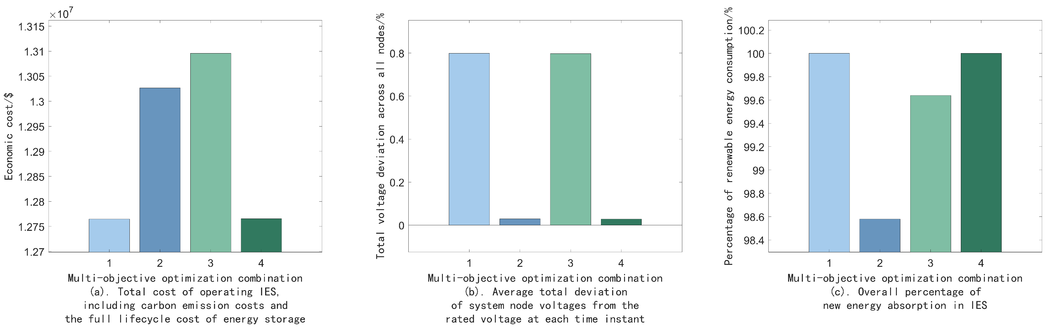
  • In planning the optimization of the proposed model, we derived the location and sizing of hybrid energy storage devices, as well as the power and capacity variation curves for different storage systems. This further validated the effectiveness of the multi-period approach to designing hybrid energy storage presented in this study. Comparing various multi-objective combinations of our chosen indicators demonstrated that the planning results positively impact economic efficiency, power quality, and renewable energy utilization. These findings indicate that the multi-objective integrated planning method is effective in improving the overall performance and sustainability of IESs in microgrids for large buildings.
The model proposed in this paper focused on overall planning, meaning that some of the operational processes of various devices were simplified. For instance, the power transition processes in the energy storage devices and voltage changes due to battery cycle aging were omitted, and the models of the CCHP system’s components were linearized. Although we made these simplifications in order to reduce the computational complexity of the overall planning process, this represents a limitation of our study. In the future, we will consider more precise modeling methods and advanced algorithms, such as hierarchical optimization and machine learning-based intelligent optimization algorithms, to enhance the accuracy of the planning results. Additionally, we will extend the simulation-based work carried out in this paper to more practical experimental validation, further investigating the potential of planning optimized energy storage for IESs in microgrids for large buildings.

Author Contributions

Conceptualization, C.H., X.T. and J.A.; methodology, C.H., X.T. and J.A.; software, Z.L.; validation, Z.L., R.Z. and X.T.; formal analysis, J.A.; investigation, Z.L.; resources, X.L.; data curation, X.L.; writing—original draft preparation, Z.L.; writing—review and editing, R.Z. and G.L.; visualization, Z.L.; supervision, C.H.; project administration, X.T.; funding acquisition, C.H. All authors have read and agreed to the published version of the manuscript.

Funding

This research was funded by scientific and technological projects from State Grid Hebei Electric power CO., LTD., grant number SGHEJY00GHJS2200052.

Data Availability Statement

The dataset is available upon request from the authors.

Conflicts of Interest

The authors He Chunguang, Tan Xiaolin, and An Jiakun are employed by the company State Grid Hebei Economic Research Institute. The author Li Xuejun is employed by State Grid Handan Electric Power Supply Company. The authors Liu Zixuan, Li Gengfeng, and Zhang Runfan are from the School of Electrical Engineering, Xi’an Jiaotong University. The authors declare that this study received funding for scientific and technological projects from the State Grid Corporation of China under grant number SGHEY00GHJS2200052. The funder was involved in this study in providing research direction and ideas.

Appendix A

The following table lists all the variable and parameter symbols used in this article.
Table A1. Variable symbols and their descriptions.
SymbolDescriptionSymbolDescription
q i , n MT , q i , n BLR , and q i , n EH Heat output of the microturbine, natural gas boiler, and electric heater V n G Consumption of natural gas per unit time
p i , n MT Electrical output power of microturbine p n GP Total electricity purchased from grid per unit time
v i , n MT and v i , n BLR Amount of natural gas consumed by microturbine and gas boiler E set and P set Installed capacity/power of energy storage
p i , n EH and p i , n EH Electrical power consumption of electric heater and chiller C Rec Cost of energy storage recovery
r i , n EC and r i , n ACH Cooling output of electric chiller and absorption chiller V i * Normalized value of voltage at node i
q i , n ACH Heat input of absorption chiller P energy real Total new energy output power of actual operation of system
p i , n dCAES , p i , n cCAES , p i , n dBATT , and p i , n cBATT Discharge/charge power of CAES/BESS f k and F k kth objective function and underlying utility function for kth objective
e i , n CAES and e i , n BATT Remaining energy of CAES system/BESS P run Set of operational state variables for each device in system
p i , n cEVCS and p i , n dEVCS Charging/discharging power provided by charging station to electric vehicleUMatrix of 0–1 variables for operating states of hybrid energy storage devices
e i , n EV Remaining energy of electric vehicle P run EU and P run ES Set of operational state variables for equipment related to system’s energy supply and hybrid energy storage devices
P i , n and Q i , n Active and reactive power flows into node i in underlying distribution network P i CAES and P i BATT Designed installed power of CAES/BESS devices
p i , n and q i , n Injected power of all devices accessing node i U i , n cCAES , U i , n dCAES , U i , n cBATT , and U i , n dBATT State of charge and discharge flags of CAES/BESS devices
p i , n GP Power purchased from grid X i CAES and X i BATT Flag variable for siting of CAES/BESS device
p i , n PV and p i , n WTG Output power from photovoltaic and wind power systems E i CAES and E i BATT Installed capacity of CAES/BESS units
V i , n Voltage magnitude at node i
Table A2. Parameter symbols and their descriptions.
SymbolDescriptionSymbolDescription
η e MT and η l MT Electrical efficiency and heat loss coefficient of microturbine m gas and m grid Carbon emission factor for natural gas and grid
L ng Lower heating value of natural gas C E ES and C P ES Unit cost of storage capacity and power
n h Boiler efficiencyYService life in years of system design
C op EH , C op EC , and C op ACH Coefficients of performance (COPs) of electric heater, electric chiller, and absorption chiller C E OM and C P OM Maintenance cost per unit of energy storage capacity and power
T BATT and T CAES l Power variation cycle of BESS and lth power variation cycle of CAES system C labor Cost per person per year of maintenance personnel
N T Ratio of power variation cycle of CAES system to BESS n labor Number of energy storage system operation and maintenance personnel
E i , n CAES 0 and E i , n BATT 0 Initial energy of CAES/BESS units C C R Replacement cost per unit of energy storage capacity
n c CAES , n d CAES , n c BATT , and n d BATT Charging and discharging efficiency of CAES/BESS unitsrStandard discount rate or benchmark rate of return
E i , n EV 0 Initial energy (initial state of charge) of electric vehicle F EOL End-of-life cost ratio
n c EVCS and n d EVCS Charging and discharging efficiency of EV charging station P energy theory Total theoretical maximum new energy output power
S i Set of child nodes for grid node i f k max and f k min Theoretical maximum and minimum of kth objective function
N Set of all nodes of microgrid ω 1 , ω 2 , and ω 3 Weights corresponding to each type of utility function
p i , n LOAD Electrical load V i , n lower and V i , n upper Lower and upper bounds of voltage magnitude at node i
θ ( i ) Previous node connected to node i r i , n load and q i , n load Cooling and heating load demands
r i and x i Line resistance and reactance with node i as endpointAMatrix of system equipment operating parameters
V 0 Reference voltage for entire microgrid P min and P max Set of lower and upper limits of output of each piece of equipment
n life Designed usage time of energy storage systemB, C, H, M, R, and GUpper limit of boiler heat power, electric chiller’s power, electric heater’s power, microturbine’s electrical power, absorption chiller’s cooling power, and power purchases per unit of time on grid
N S Number of scenarios X i canset Flag for node being installable
TTotal number of time intervals N CAES and N BATT Total number of nodes selected for installation of CAES/BESS
n n scen Frequency of nth scenario d depth CAES and d depth BATT Lower limit of CAES/BESS discharge depth
Δ T Time interval within each unit of time P MAX CAES , P MIN MAX , P MAX BATT , and P MIN BATT Upper and lower limits of installed power of CAES/BESS device
C P G and C P E Purchase cost per unit of natural gas and time-of-use price from grid E MAX CAES , E MIN CAES , E MAX BATT , and E MIN BATT Upper and lower limits of installed capacity of CAES/BESS device

References

  1. Zhang, J.; Chen, J.; Ji, X.N.; Sun, H.Z.; Liu, J. Low-carbon economic dispatch of integrated energy system based on liquid carbon dioxide energy storage. Front. Energy Res. 2023, 10, 1051630. [Google Scholar] [CrossRef]
  2. Wang, L.Y.; Lin, J.L.; Dong, H.Q.; Wang, Y.Q.; Zeng, M. Demand response comprehensive incentive mechanism-based multi-time scale optimization scheduling for park integrated energy system. Energy 2023, 270, 126893. [Google Scholar] [CrossRef]
  3. Li, Y.; Wang, B.; Yang, Z.; Li, J.Z.; Chen, C. Hierarchical stochastic scheduling of multi-community integrated energy systems in uncertain environments via Stackelberg game. Appl. Energy 2022, 308, 118392. [Google Scholar] [CrossRef]
  4. Moghadam, E.A.; Gord, F.M.; Abadi, K.M. Sensitivity analysis and working fluid selection for a biogas-fueled hybrid energy system based on nearly zero energy building concept: A case study. J. Clean. Prod. 2024, 435, 140499. [Google Scholar] [CrossRef]
  5. Yao, G.; Chen, Y.; Lin, Y.X.; Wang, Y.G. Energy-Saving Design Strategies of Zero-Energy Solar Buildings-A Case Study of the Third Solar Decathlon China. Buildings 2023, 13, 405. [Google Scholar] [CrossRef]
  6. Guo, J.C.; Wu, D.; Wang, Y.Y.; Wang, L.M.; Guo, H.Y. Co-optimization method research and comprehensive benefits analysis of regional integrated energy system. Appl. Energy 2023, 340, 121034. [Google Scholar] [CrossRef]
  7. Kingston, T.; Guada, B.A. Simulated Use Performance of an Integrated Energy System for Thermal and Power Management with Micro-combined Heat and Power in Nano-grid Environments. ASHRAE Trans. 2023, 129, 536–544. [Google Scholar]
  8. Mianaei, P.K.; Aliahmadi, M.; Faghri, S.; Ensaf, M.; Ghasemi, A.; Abdoos, A.A. Chance-constrained programming for optimal scheduling of combined cooling, heating, and power-based microgrid coupled with flexible technologies. Sustain. Cities Soc. 2022, 77, 103502. [Google Scholar] [CrossRef]
  9. Hu, J.F.; Shan, Y.H.; Yang, Y.; Parisio, A.; Li, Y.; Amjady, N.; Islam, S.; Cheng, K.W.; Guerrero, J.M.; Rodriguez, J. Economic Model Predictive Control for Microgrid Optimization: A Review. IEEE Trans. Smart Grid 2024, 15, 472–484. [Google Scholar] [CrossRef]
  10. Liu, J.; Chen, X.; Yang, H.X.; Shan, K. Hybrid renewable energy applications in zero-energy buildings and communities integrating battery and hydrogen vehicle storage. Appl. Energy 2021, 290, 116733. [Google Scholar] [CrossRef]
  11. Hu, J.J.; Wang, Y.D.; Dong, L. Low carbon-oriented planning of shared energy storage station for multiple integrated energy systems considering energy-carbon flow and carbon emission reduction. Energy 2024, 290, 130139. [Google Scholar] [CrossRef]
  12. Sunny, M.R.; Ali, T.; Aghaloo, K.; Wang, K. Techno-economic feasibility of stand-alone hybrid energy system with battery storage in educational buildings: A case study of Uttara University. Energy Build. 2024, 304, 113852. [Google Scholar] [CrossRef]
  13. Belkhier, Y.; Oubelaid, A. Novel design and adaptive coordinated energy management of hybrid fuel-cells/tidal/wind/PV array energy systems with battery storage for microgrids. Energy Storage 2024, 6, e556. [Google Scholar] [CrossRef]
  14. Mussetta, M.; Le, X.C.; Trinh, T.H.; Doan, A.T.; Duong, M.Q.; Tanasiev, G.N. An Overview of the Multilevel Control Scheme Utilized by Microgrids. Energies 2024, 17, 3947. [Google Scholar] [CrossRef]
  15. Zhu, M.S.; Fang, J.K.; Ai, X.M.; Cui, S.C.; Feng, Y.; Li, P.; Zhang, Y.H.; Zheng, Y.L.; Chen, Z.; Wen, J.Y. A comprehensive methodology for optimal planning of remote integrated energy systems. Energy 2023, 285, 129443. [Google Scholar] [CrossRef]
  16. Li, Z.C.; Xia, Y.H.; Bo, Y.L.; Wei, W. Optimal planning for electricity-hydrogen integrated energy system considering multiple timescale operations and representative time-period selection. Appl. Energy 2024, 362, 122965. [Google Scholar] [CrossRef]
  17. Lei, Z.J.; Yu, H.; Li, P.; Ji, H.R.; Yan, J.Y.; Song, G.Y.; Wang, C.S. A compact time horizon compression method for planning community integrated energy systems with long-term energy storage. Appl. Energy 2024, 361, 122912. [Google Scholar] [CrossRef]
  18. Wang, T.L.; Huo, T.Y.; Li, H.H. Bi-Layer Planning of Integrated Energy System by Incorporating Power-to-Gas and Ground Source Heat Pump for Curtailed Wind Power and Economic Cost Reduction. Energies 2024, 17, 1447. [Google Scholar] [CrossRef]
  19. Chen, L.; Yang, D.D.; Cai, J.; Yan, Y. Robust optimization based coordinated network and source planning of integrated energy systems. Int. J. Electr. Power Energy Syst. 2024, 157, 109864. [Google Scholar] [CrossRef]
  20. Dong, Y.C.; Wang, C.; Zhang, H.L.; Zhou, X.J. A novel multi-objective optimization framework for optimal integrated energy system planning with demand response under multiple uncertainties. Inf. Sci. 2024, 663, 120252. [Google Scholar] [CrossRef]
  21. Dong, Y.C.; Zhang, H.L.; Ma, P.; Wang, C.; Zhou, X.J. A hybrid robust-interval optimization approach for integrated energy systems planning under uncertainties. Energy 2023, 274, 127267. [Google Scholar] [CrossRef]
  22. Dong, W.K.; Lu, Z.G.; He, L.C.; Geng, L.J.; Guo, X.Q.; Zhang, J.F. Low-carbon optimal planning of an integrated energy station considering combined power-to-gas and gas-fired units equipped with carbon capture systems. Int. J. Electr. Power Energy Syst. 2022, 138, 107966. [Google Scholar] [CrossRef]
  23. Li, P.; Jiang, L.; Zhang, C.Y.; Wang, J.H.; Wang, N.; Liu, H.T.; Dou, Z.L.; Pan, Y.P.; Zhou, X.C.; Zeng, P.L. Coordinated planning of integrated electricity-heat-gas energy system considering renewable energy consumption. IET Gener. Transm. Distrib. 2022, 17, 3232–3244. [Google Scholar] [CrossRef]
  24. Li, F.; Lu, S.R.; Cao, C.W.; Feng, J. Operation Optimization of Regional Integrated Energy System Considering the Responsibility of Renewable Energy Consumption and Carbon Emission Trading. Electronics 2021, 10, 2677. [Google Scholar] [CrossRef]
  25. Gao, Y.; Zhang, X.; Xu, X.; Liu, L.; Zhao, Y.; Zhang, S. Application and research progress of phase change energy storage in new energy utilization. J. Mol. Liq. 2021, 343, 117554. [Google Scholar] [CrossRef]
  26. He, Y.; Guo, S.; Zhou, J.X.; Ye, J.L.; Huang, J.; Zheng, K.; Du, X.R. Multi-objective planning-operation co-optimization of renewable energy system with hybrid energy storages. Renew. Energy 2022, 184, 776–790. [Google Scholar] [CrossRef]
  27. Dong, H.L.; Fang, Z.J.; Ibrahim, A.; Cai, J. Optimized Operation of Integrated Energy Microgrid with Energy Storage Based on Short-Term Load Forecasting. Electronics 2022, 11, 22. [Google Scholar] [CrossRef]
  28. Wu, G.; Li, T.; Xu, W.T.; Xiang, Y.; Su, Y.C.; Liu, J.W.; Liu, F. Chance-constrained energy-reserve co-optimization scheduling of wind-photovoltaic-hydrogen integrated energy systems. Int. J. Hydrogen Energy 2023, 48, 6892–6905. [Google Scholar] [CrossRef]
  29. Kiryanova, N.G.; Matrenin, P.V.; Mitrofanov, S.V.; Kokin, S.E.; Safaraliev, M.K. Hydrogen energy storage systems to improve wind power plant efficiency considering electricity tariff dynamics. Int. J. Hydrogen Energy 2022, 47, 10156–10165. [Google Scholar] [CrossRef]
  30. Zeng, X.Q.; Xiao, P.; Zhou, Y.; Li, H.J. Hybrid energy storage for the optimized configuration of integrated energy system considering battery-life attenuation. J. Eng.-JOE 2023, 2023, e12331. [Google Scholar] [CrossRef]
  31. Gao, M.F.; Han, Z.H.; Zhao, B.; Li, P.; Wu, D.; Li, P. Optimal planning method of multi-energy storage systems based on the power response analysis in the integrated energy system. J. Energy Storage 2023, 73, 109015. [Google Scholar] [CrossRef]
  32. Wang, Y.L.; Zhang, Y.L.; Xue, L.; Liu, C.; Song, F.H.; Sun, Y.L.; Liu, Y.; Che, B. Research on planning optimization of integrated energy system based on the differential features of hybrid energy storage system. J. Energy Storage 2022, 55, 105368. [Google Scholar] [CrossRef]
  33. Chen, C.M.; Liu, C.; Ma, L.Y.; Chen, T.W.; Wei, Y.Q.; Qiu, W.Q.; Lin, Z.Z.; Li, Z.Y. Cooperative-game-based joint planning and cost allocation for multiple park-level integrated energy systems with shared energy storage. J. Energy Storage 2023, 73, 108861. [Google Scholar] [CrossRef]
  34. Zhang, L.Y.; Guo, J.X.; Yu, X.R.; Hui, G.; Liu, N.; Ren, D.D.; Wang, J.J. Optimization of Integrated Energy Systems Based on Two-Step Decoupling Method. Electronics 2023, 13, 2045. [Google Scholar] [CrossRef]
  35. Hou, E.G.; Xu, Y.L.; Tang, J.R.; Wang, Z. Strategy of Flywheel-Battery Hybrid Energy Storage Based on Optimized Variational Mode Decomposition for Wind Power Suppression. Electronics 2024, 13, 1362. [Google Scholar] [CrossRef]
  36. Xing, C.; Xiao, J.J.; Li, P.Q.; Xi, X.Z.; Chen, Y.H.; Guo, Q. Adaptive Virtual Inertial Control and Virtual Droop Control Coordinated Control Strategy for Hybrid Energy Storage Taking into Account State of Charge Optimization. Electronics 2024, 13, 1228. [Google Scholar] [CrossRef]
  37. Wang, J.X.; Wei, J.D.; Zhu, Y.C.; Wang, X.L. The Reliability and Operational Test System of a Power Grid with Large-scale Renewable Integration. CSEE J. Power Energy Syst. 2020, 6, 704–711. [Google Scholar]
Figure 1. Distributed integrated energy system.
Electronics 13 03844 g001
Figure 2. Theoretical total new energy output of integrated energy system.
Electronics 13 03844 g002
Figure 3. Total load demands of various types in integrated energy system.
Electronics 13 03844 g003
Figure 4. Results of optimizing siting and capacity planning for hybrid energy storage system equipment.
Electronics 13 03844 g004
Figure 5. Charging and discharging power of hybrid energy storage system devices.
Electronics 13 03844 g005
Figure 6. Remaining energy during charging and discharging processes of hybrid energy storage system devices.
Electronics 13 03844 g006
Figure 7. The distributed integrated energy system.
Electronics 13 03844 g007
Table 1. Parameters of the integrated energy system.
Equipment TypeEquipment ParameterParameter Value
MicroturbineElectrical efficiency η e MT 0.3
Heat loss coefficient η l MT 2 %
Upper limit of the electrical power M150 kW
Natural gas boilerBoiler efficiency n h 0.9
Upper limit of heat B100 kW
Electric heaterCOP C op EH 3.5
Upper limit of power H400 kW
Electric chillerCOP C op EC 3.5
Upper limit of power C400 kW
Absorption chillerCOP C op ACH 1.38
Upper limit of refrigeration power R200 kW
BatteryRatio of the power variation cycle N T 4
Charging efficiency n c BATT 0.9
Discharging efficiency n d ES , BATT 0.9
Unit cost of storage capacity C E ES , BATT 168 USD/kWh
Unit cost of storage power C P ES , BATT 70 USD/kW
Maintenance cost per unit of capacity C E OM , BATT 4.2 USD/kWh
Maintenance cost per unit of power C P OM , BATT 3.5 USD/kW
Replacement cost per unit of capacity C C R , BATT 168 USD/kWh
End-of-life cost ratio F EOL BATT 0.05
Standard discount rate r BATT 0.08
Lower limit of discharge depth d depth BATT 0.2
CAESCharging efficiency n c CAES 0.6
Discharging efficiency n d CAES 0.6
Unit cost of storage capacity C E ES , CAES 14 USD/kWh
Unit cost of storage power C P ES , CAES 1120 USD/kW
Maintenance cost per unit of capacity C E OM , CAES 0.28 USD/kWh
Maintenance cost per unit of power C P OM , CAES 2.8 USD/kW
End-of-life cost ratio F EOL CAES 0.1
Standard discount rate r CAES 0.08
Lower limit of discharge depth d depth CAES 0
EVCSCharging efficiency n c EVCS 1
Discharging efficiency n d EVCS 1
Natural gasPurchase cost C P G 0.14 USD/m3
Carbon emission factor m gas 1 kgCO2/m3
Lower heating value of natural gas L ng 9.78 (kW·h)/m3
Table 2. Time-share tariff.
TimePrices
0:00–7:000.0434 USD/kWh
7:00–10:00/15:00–18:00/21:00–24:000.084 USD/kWh
10:00–15:00/18:00–21:000.1386 USD/kWh
Disclaimer/Publisher’s Note: The statements, opinions and data contained in all publications are solely those of the individual author(s) and contributor(s) and not of MDPI and/or the editor(s). MDPI and/or the editor(s) disclaim responsibility for any injury to people or property resulting from any ideas, methods, instructions or products referred to in the content.

