Article

Increasing Microwave Penetration Depth in the Human Body by a Complex Impedance Match of Skin Interface with a Two-Layered Medium

by
Meng-Lu Ma
1,
Deshuang Zhao
1,2,*,
Zai-Jun Hu
1,
Yiling Wang
3,4,
Feng Liang
1 and
Bing-Zhong Wang
1
1
School of Physics, University of Electronic Science and Technology of China, Chengdu 611731, China
2
The Yangtze Delta Region Institute (Huzhou), University of Electronic Science and Technology of China, Huzhou 313001, China
3
Sichuan Cancer Hospital, Chengdu 610041, China
4
School of Medicine, University of Electronic Science and Technology of China, Chengdu 610054, China
*
Author to whom correspondence should be addressed.
Electronics 2024, 13(19), 3915; https://doi.org/10.3390/electronics13193915
Submission received: 1 September 2024 / Revised: 28 September 2024 / Accepted: 30 September 2024 / Published: 3 October 2024

Abstract

:
Increasing the radiated microwave penetration depth is the key to breaking the limitations of the action range in the lossy human body for non-invasive microwave technologies such as microwave hyperthermia, microwave imaging, and the wireless charging of implantable devices. This paper presents a method to increase the radiated microwave penetration depth in the lossy human body by matching the complex impedance of the skin surface using a two-layered medium. The proposed method avoided the impedance mismatch caused by the real impedance assumption of the skin surface for a lossy human body when using the traditional method. Therefore, the reflection loss on the skin surface could be significantly reduced, thereby increasing the penetration depth of the radiated microwave. Moreover, this method could select a suitable medium for the matched Layer 1 by adjusting the relative permittivity of the matched Layer 2, which is more practical than the single-layer-medium optimization method where the relative permittivity cannot be adjusted. The full-wave simulation results showed that the microwave penetration depth of the proposed method at an input power of 0.5 W was 21.01 mm and could significantly increase by 83.18% and 21.37% compared with those in a no-matched layer model and in a traditional 1/4 wavelength medium match method, respectively.

1. Introduction

In recent years, non-invasive microwave medical technologies (such as non-invasive microwave imaging [1,2,3,4] and non-invasive microwave hyperthermia [5,6,7,8]), as well as implantable medical devices used for sensing and drug delivery [9,10,11,12], have seen widespread and significant applications in modern medicine. Non-invasive microwave technology has the advantage of high safety and a short recovery time because it avoids the invasive manipulation of the body and reduces the risk of infections and complications, which greatly improves the safety of medical treatment and the patient experience. Similarly, wireless power transmission technology that utilizes radiated microwaves incident from outside the body to charge implantable devices does not require invasive manipulation of the human body, making it a safer and more convenient method of charging. The effective implementation of the above non-invasive techniques depends on the effective transfer of radiated microwave power into the human body. However, during the propagation of the radiated microwaves from the air into the human body, as shown in Figure 1a, energy attenuation in the target direction occurs due to reflections on the skin surface, heat loss inside the human body due to tissue conductivity, and diffuse propagation in different directions. These losses in the transmission path reduce the penetration depth and action range of microwaves inside the human body, thus limiting the development of microwaves in the above application scenarios.
To suppress the loss caused by microwave diffusion propagation, a field-focusing method based on the convex optimization algorithm has been proposed [13]. This method works by focusing the microwave field in the target direction, as shown in Figure 1b, thus effectively reducing the loss due to microwave diffusion propagation, which further increases the penetration depth. However, this method cannot avoid the loss of reflection on the skin surface. The reflection coefficient of microwaves incident from the air to the human body on the skin surface is high [14]. A large part of the energy is lost due to interfacial reflection, which significantly reduces the energy transmitted into the human body through the skin surface, thus having a greater impact on the microwave penetration depth. Therefore, reducing the microwave reflection loss on the skin surface is important to increase the microwave penetration depth.
The reflection loss from the air–skin interface is caused by the impedance mismatch between the air and the skin surface of the human body. Some methods improve impedance matching by inserting a suitable liquid or monolayer medium, which can suppress microwave reflection loss on the skin surface to some extent [15,16]. However, However, to achieve better impedance matching, the thickness and electrical parameters of the loaded medium need to be optimized. The impedance match method based on the 1/4 wavelength matching theory allows for the analytical calculation of the thickness and relative permittivity of the matching medium, thereby effectively avoiding complex optimization processes. However, it is often challenging to directly find materials with the required relative permittivity. To enhance practicality, methods have been proposed for impedance matching by loading a single-layered metasurface [17,18]. The substrate of the metasurface can be made from commonly available materials, requiring only the design of appropriate periodic metal structures on the surface to achieve impedance matching, thus overcoming the limitations of material selection. These methods require assuming the impedance of the skin surface to be a real impedance. However, all tissues in the human body are a lossy medium, so the impedance on the skin surface is actually a complex impedance. Therefore, as shown in Figure 1c, loading the matching layer corresponding with the above methods leads to an impedance mismatch, which still results in reflection losses. Further, it also limits the penetration depth of the radiated microwaves inside the lossy human body.
Therefore, we proposed a penetration depth increase method for radiated microwaves in the lossy human body by matching the complex impedance of the skin surface using a two-layered medium. This method could effectively avoid an impedance mismatch due to a real impedance assumption on the skin surface of the lossy human body, thus increasing the microwave penetration depth. Initially, we attempted a single-layer-medium optimized match method, which involved optimizing the relative permittivity of the matched layer to match the complex impedance model of the skin surface. However, finding a practical medium with a permittivity equal to the optimal value was difficult. To improve practicality, a two-layered match method was proposed. In this approach, the relative permittivity of the matched Layer 2 could be freely chosen, while the relative permittivity and thickness of the matched Layer 1 were analytically calculated based on the parameters of the matched Layer 2. This design allowed for adjustable parameters in the matched Layer 1, making it easier to find a matching actual medium, thereby significantly enhancing the practicality of the method. The proposed method could significantly reduce the reflection coefficient of the interface, thus improving the microwave energy transmitted into the lossy human body, which then increased the penetration depth of the radiated microwaves. The advantages and effectiveness of this method were also analyzed and verified using full-wave simulations.

2. Method

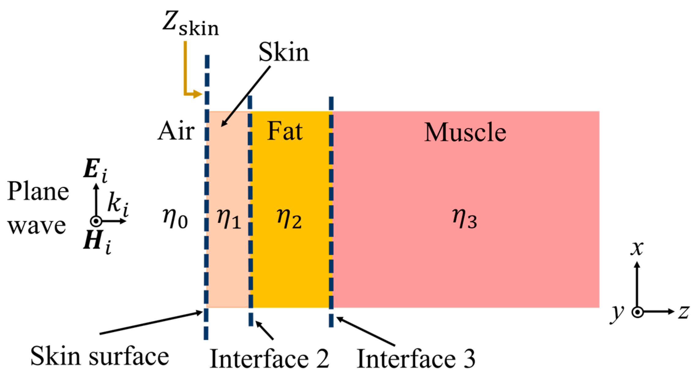
2.1. Impedance Deduction of the Skin Surface

A simplified layered model of a superficial human body was created according to the guidelines developed by the European Society for Hyperthermic Oncology [19]. This model is shown in Figure 2, and consisted of the following three tissues: 1.8 mm skin, 10 mm fat, and 90 mm muscle. Their corresponding electrical parameters are shown in Table 1. In scenarios such as microwave imaging, the wireless charging of implantable devices, and non-invasive microwave hyperthermia, the microwave source is typically on the outside of the body, delivering microwave energy to the tissues by radiation. Therefore, the microwave radiation source was constructed in the free space on the left side of the superficial human body model, such as a plane wave vertically incident along the z-direction.
During the propagation of radiated microwaves, reflections occur at the skin surface due to the difference in wave impedance between the air and the skin surface of the human body. Microwave energy loss due to interfacial reflection can further limit the microwave penetration depth inside the human body. To further analyze the interfacial reflection loss, the impedance on each interface in the human body model needed to be calculated.
The skin, fat, and muscle in Figure 2 were the 1st, 2nd, and 3rd tissue layers of the human body model, respectively. The characteristic impedance of the nth tissue layer was η n = μ / ( ε 0 ε r n j σ n / ω ) . The skin surface, the skin–fat interface, and the fat–muscle interface in Figure 2 were Interface 1, 2, and 3, respectively. The impedance Z i f a c e n on the interface n could be calculated as follows:
Z i f a c e n = η n Z i f a c e n + 1 + η n tanh γ n d n η n + Z i f a c e n + 1 tanh γ n d n     ( n = 1,2 ) η n                                               ( n = 3 ) ,
where γ n is the propagation constant of the plane wave in the nth tissue layer and d n is the thickness of the nth tissue layer.
According to (1), the impedance on the skin surface (Interface 1) of the lossy human body at 2.45 GHz was Z s k i n =   Z i f a c e 1 = 57.51 j 73.80 .
The reflection coefficient ( Γ s k i n ) of a vertically incident plane wave on the skin surface can be calculated as follows:
Γ s k i n = Z s k i n η 0 Z s k i n + η 0     ,
where η 0 is the characteristic impedance of the microwaves in the air.
According to (2), the reflection coefficient of microwaves on the skin surface at 2.45 GHz could be calculated as Γ s k i n = 0.74 . Therefore, 54.76% of the microwave energy was lost by reflection and less than half of the microwave energy could be transmitted into the human body, which limited the penetration depth of the radiated microwaves.

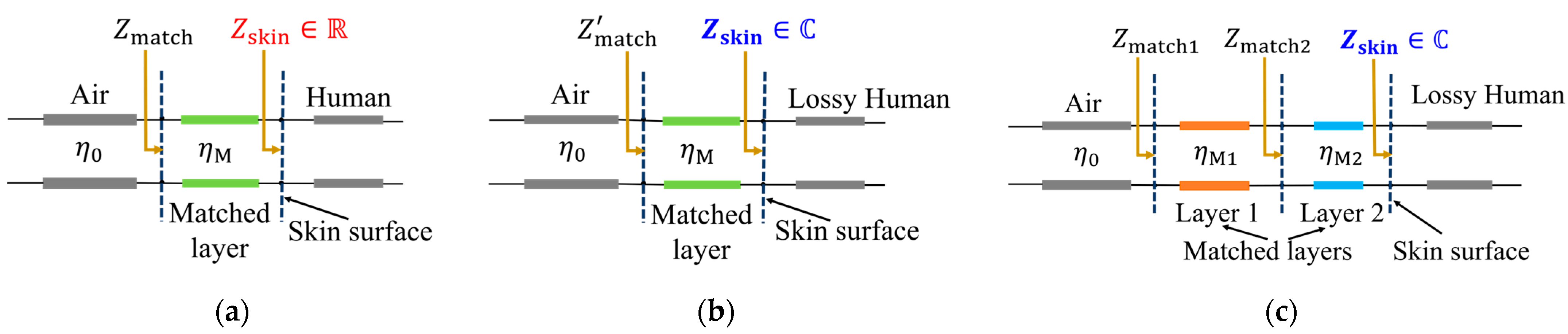
2.2. A Single-Layered Medium Match for a Real Impedance Model of the Skin Surface

Increasing the penetration depth of radiated microwaves in the human body can be achieved by matching the impedance of the air and human skin surfaces to reduce microwave interfacial reflection loss. To simplify the impedance matching problem, the common approach is to assume that the impedance of the skin surface Z s k i n is a real impedance Z s k i n R [18], and then the matching between the real impedance model of the skin surface and the wave impedance in the air can be achieved by loading a single-layer medium or the metasurface [17,18].
The traditional method is the 1/4 wavelength match method, which uses a single-layered uniform ideal medium with a characteristic impedance η M and thickness d M = λ M / 4 to match the real impedance model of the skin surface, as shown in Figure 3a. λ M is the wavelength of the microwaves in the matched layer.
The characteristic impedance η M of the matched layer can be calculated by making Z m a t c h = η 0 , as follows:
η M = η 0 R e Z s k i n     ,
where Z m a t c h is the impedance on the air-matched layer interface. The reflection coefficient on the matched layer surface is Γ = 0 . It has been shown that this method can achieve the matching of real impedance models of the skin surface using a single-layered medium.

2.3. A Single-Layered Medium Match for a Complex Impedance Model of the Skin Surface

According to the impedance deduction of the air–skin interface in Section 2.1, the impedance of the skin surface in the superficial lossy human body was a complex impedance. In order to more accurately analyze the matching of skin surface impedances, complex impedance models of the skin surface ( Z s k i n C ) were developed for the lossy human body. When only the 1/4 wavelength single-layered medium from Section 2.2 was loaded onto the complex impedance model of the skin surface, as shown in Figure 3b, the impedance Z m a t c h of the air-matched layer interface could be calculated as follows:
Z m a t c h = η M Z s k i n + j η M tan β M d M η M + j Z s k i n tan β M d M     ,
The corresponding reflection coefficient of the air-matched layer interface at 2.45 GHz was Γ = Z m a t c h η 0 Z m a t c h + η 0 = 0.54 . Although this reflection coefficient was reduced from that without a matched layer, 29.16% of the microwave energy was still reflected into the air and there was still interfacial reflection loss. Therefore, the 1/4 wavelength match method did not achieve the full matching of the complex impedance of the skin surface and there were still reflection losses that limited the microwave penetration depth inside the lossy human body.
To further improve the impedance matching effect, optimization of the relative permittivity and thickness of a single matched layer is possible. Theoretically, optimization to obtain an appropriate relative permittivity and thickness can provide better matching results for the complex impedance model of a skin surface, thereby increasing the penetration depth of the microwaves in a lossy human body. However, the optimal relative permittivity obtained is uncontrollable, making it difficult to find an actual medium that exactly matches this optimal value, thus limiting its practical application.

2.4. A Two-Layered Medium Match for a Complex Impedance Model of the Skin Surface

To further enhance the practicality of the match method while effectively increasing the microwave penetration depth in a lossy human body, we proposed a two-layered medium match method with controllable relative permittivity for the complex impedance model of the skin surface.
This method achieved an impedance match on the skin surface by loading a two-layered uniform medium, as shown in Figure 3c. The matched Layer 2 was used to convert Z s k i n to a real impedance Z m a t c h 2 , and the matched Layer 1 was further used to achieve the matching of the impedance Z m a t c h 2 with η 0 . The relative permittivity of the matched Layer 2 could be arbitrarily selected and was assumed to be ε r M 2 . The corresponding characteristic impedance of the matched Layer 2 was η M 2 = μ / ( ε 0 ε r M 2 ) , and the reflection coefficient on the skin surface was as follows:
Γ s k i n = Z s k i n η M 2 Z s k i n + η M 2 = Γ s k i n e j φ s k i n ,
where φ s k i n is the phase of Γ s k i n .
The minimum thickness d M 2 of the matched Layer 2 corresponding with the transformation of Z m a t c h 2 into a real impedance could be calculated as follows:
d M 2 = φ s k i n 2 π λ M 2 2                                         ( φ s k i n > 0 ) ( φ s k i n + π ) 2 π λ M 2 2                 ( φ s k i n < 0 ) .
The corresponding impedance Z m a t c h 2 on the surface of the matched Layer 2 was as follows:
Z m a t c h 2 = η M 2 Z s k i n + j η M 2 tan β M 2 d M 2 η M 2 + j Z s k i n tan β M 2 d M 2     ,
where β M 2 is the phase constant of the electromagnetic wave in the matched Layer 2.
Matching the impedance Z m a t c h 2 with η 0 was realized by loading the matched Layer 1 with thickness d M 1 , as follows:
d M 1 = λ M 1 / 4 ,
where λ M 1 is the wavelength of the microwave in the matched Layer 1. The characteristic impedance of the matched Layer 1 could be calculated according to (3) as follows:
η M 1 = η 0 Z m a t c h 2 ,
The relative permittivity ε r M 1 of the matching Layer 1 was as follows:
ε r M 1 = ( η 0 η M 1 ) 2 .
At this time, the impedance on the air-matched Layer 1 interface Z m a t c h 1 was equal to η 0 , so the reflection coefficient on the air-matched Layer 1 interface at 2.45 GHz was Γ = Z m a t c h 1 η 0 Z m a t c h 1 + η 0 = 0 , which theoretically eliminated the reflection loss. Therefore, the proposed method could increase the microwave energy transmitted into the human body, which is promising to further increase the microwave penetration depth inside a lossy human body.
In addition, according to (6), (8), and (10), the correspondence between the different parameters ( ε r M 2 ,   ε r M 1 , d M 2 ,   a n d d M 1 ) of the two matched layers at 2.45 GHz could be obtained, as shown in Figure 4. Among them, the relative permittivity ε r M 2 of the matched Layer 2 in this method could be arbitrarily selected. The relative permittivity ε r M 1 of the matching Layer 1 was variable with the change of ε r M 2 , so that the appropriate ε r M 1 could be chosen by controlling ε r M 2 . Therefore, the proposed method could improve practicality while satisfying the increased microwave penetration depth.
For example, when the matching Layer 2 was air, i.e., the relative permittivity was ε r M 2 = 1 , the relative permittivity of the corresponding matching Layer 1 was ε r M 1 = 6.82 . The medium mica (glass-bonded) has a relative permittivity equal to 6.7 , very close to ε r M 1 , so it could be used as the matched Layer 1.

3. Simulations and Results

3.1. Simulation Models

In order to verify the effectiveness of the proposed method to match the complex impedance model of the skin surface and increase the microwave penetration depth, four full-wave simulations of the radiated microwave propagation process corresponding with the different impedance match methods were carried out for the layered model of a lossy human body using CST Microwave Studio.
The four simulations in the lossy human body model (as shown in Figure 2) included (1) without a matched layer (no-matched layer), (2) using the 1/4 wavelength single-layered medium match method for real impedance models of the skin surface (Method 1), (3) using the single-layer-medium optimized match method for complex impedance models of the skin surface (Method 2), and (4) using the two-layered medium match method for complex impedance models (Method 3).
In Method 1, the relative permittivity and the thickness of the single matched layer were ε r M = 6.54 and d M = 12   m m , respectively. In Method 2, the optimum relative permittivity and the thickness of the matched layer were ε r M = 9.34 and d M = 13.87   m m , respectively. In Method 3, the relative permittivity and the thickness of the matched Layer 2 (air) were ε r M 2 = 1 and d M 2 = 3.85   m m , respectively. The relative permittivity and the thickness of the matched Layer 1 (mica (glass-bonded)) were ε r M 1 = 6.7 and d M 1 = 11.72   m m , respectively. The microwave source was a plane wave vertically incident along the z-direction with a central frequency of 2.45 GHz (which was within the Industrial Scientific Medical Band (ISMB)). The input power P i n of the 61.225 mm × 61.225 mm area was 0.5 W. The above four full-wave simulations were carried out under the same periodic boundary conditions. It should be noted that the above match methods could exhibit sensitivity to variations in boundary conditions in practical applications.

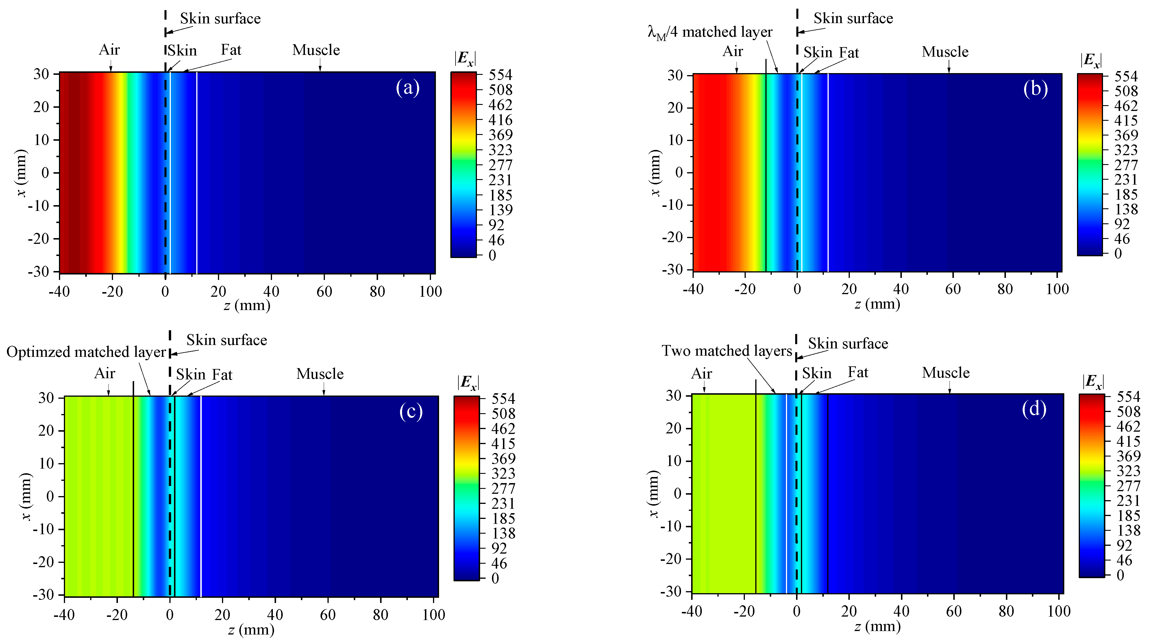
3.2. Full-Wave Results

The electric field and energy flow density distributions obtained from the above four simulations are shown in Figure 5 and Figure 6, respectively. It was found that the electric fields and energy flow densities inside the human body were greater after loading the matched layer onto the skin surface than without the matched layer. The two impedance match methods (Method 2 and Method 3) for the complex impedance model had larger electric fields and energy flow densities on the skin surface than the 1/4 wavelength match method (Method 1) for the real impedance model. Method 2 and Method 3 could transmit more microwave energy into a lossy human body.

4. Discussion

4.1. Comparison of Different Impedance Match Methods on Microwave Penetration Effects

In order to further analyze the advantages of the proposed method, we compared the interfacial reflection coefficients, the field distribution, and the microwave penetration depths in the above four simulations.
The reflection coefficients of the microwaves from Method 2 and Method 3 at an input power P i n = 0.5   W were Γ = 0.002 and Γ = 0.015 , respectively. They were 99.79% and 97.99% lower than Γ = 0.746 in the model without a matched layer, respectively, and 99.70% and 97.19% lower than Γ = 0.533 in Method 1 with the 1/4 wavelength matched layer, respectively. This evidenced that the two impedance match methods (Method 2 and Method 3) for the complex impedance model of a skin surface could significantly reduce the microwave interface reflection loss for a complex impedance model of the skin surface.
Based on the simulation results, the electric field and energy flow density distribution comparison curves on the z-axis for the different methods at an input power P i n = 0.5   W are shown in Figure 7 and Figure 8. Table 2 also shows the electric fields and energy flow density distributions of the different interfaces. Method 3 shows larger electric fields on the interfaces compared to the model without a matched layer and Method 1, with minimum growth ratios of 50.16% and 18.22%, respectively. Method 3 also shows larger energy flow densities on the interfaces compared to the model without a matched layer and Method 1, with minimum growth ratios of 125.50% and 38.62%, respectively.- Moreover, the differences in the electric fields and energy flow densities at each interface between Method 2 and Method 3 were less than 0.03 V/m and 3.11 W/m2, respectively, so that the field results obtained using the two methods were approximate. The above results indicated that the impedance match methods for a complex impedance model of the skin surface could significantly increase the microwave field entering into each tissue in a lossy human body.
When the energy flow densities were attenuated to S a v _ z = 43.86   W / m 2 (i.e., the energy flow density corresponded with e 1 of the maximum value of the electric field amplitude on the skin surface in the model without a matched layer at the input power P i n = 0.5   W ), the perpendicular distance between the corresponding position and the skin surface was defined as the penetration depth d . Table 3 shows the corresponding microwave penetration depths at different input powers P i n in the four simulations. Method 2, with a single matched layer, increased the penetration depths by 83.73 % and 21.32 % compared with the model without a matched layer and Method 1 at P i n = 0.5   W , respectively. The difference between the penetration depths at P i n = 0.5   W for Method 2 and Method 3 was 0.01 mm, and Method 3 (with two matched layers) increased the penetration depths by 83.81 % and 21.37 % compared with the model without a matched layer and Method 1, respectively.
Moreover, the penetration depth increased with an increase in the input power P i n . The increased proportions of the penetration depths in Method 3 compared with those in the model without a matched layer at P i n = 0.5   W , P i n = 2   W , and P i n = 8   W were 83.81 % , 32.86 % , and 20.96 % , respectively. The increased proportion of the penetration depth in the proposed Method 3 compared with that in the model without a matched layer did not grow with an increase in the input power. Therefore, the improved ability of the microwave penetration depth of Method 3 relative to that of the no-matched layer did not increase with an increase in input power.
From the above results, it could also be seen that the field distribution results and penetration depth results of Method 3 and Method 2 were similar, indicating that Method 3 could achieve a similar effect of penetration depth increase as Method 2. Compared with Method 2, Method 3 was not required to have a parameter optimization process and was more practical as it was able to select a suitable medium for the matched Layer 1 by adjusting the relative permittivity of the matched Layer 2.
The advantages and effectiveness of the proposed Method 3 in increasing the penetration depth of radiated microwaves in a lossy human body were proven.

4.2. Comparison of Microwave Penetration Effects of the Proposed Method at Different Frequencies Commonly Used in Medicine Applications

Different microwave frequencies are used for different medical applications such as microwave imaging, the wireless charging of implantable devices, and non-invasive microwave hyperthermia. In order to realize that the proposed Method 3 could be applied to many different medical fields, the effectiveness of the method required verification at different frequencies commonly used in medicine applications.
When the frequency changes, the electrical parameters of various tissues in the human body also change accordingly. According to η = μ / ( ε 0 ε r n j σ / ω ) , the characteristic impedance of tissues varies with changes in frequency and electrical parameters, which in turn changes the impedance at the skin surface. Theoretically, the reflection of radiated microwaves at the skin surface can be avoided by calculating the complex impedance of the skin surface in a lossy human body model at different frequencies. By using the proposed Method 3, the corresponding two-layered matched medium could be loaded onto the skin surface to achieve an increase in the penetration depth of radiated microwaves in lossy human tissues at different frequencies.
We took four frequencies commonly used in medical applications as examples (f = 0.433 GHz, 0.915 GHz, 2.45 GHz, and 3.5 GHz) [9,11,12,21,22] and validated, through four sets of full-wave simulations, that the proposed Method 3 at the input power P i n = 0.5   W enhanced microwave penetration in a lossy human model (as shown in Figure 2) at different frequencies compared with scenarios without a matched layer.
Based on the four sets of simulation results at the above four frequencies, we obtained the reflection coefficients Γ of the skin surfaces corresponding with each of them and calculated the microwave penetration depths d when the energy flow densities were attenuated to S a v _ z = 43.86   W / m 2 , as shown in Table 4. It could be seen that due to the different impedances on the skin surface at different frequencies, the corresponding reflection coefficients Γ n o in the model without a matched layer were different, and the reflection coefficients were the largest at f = 3.5 GHz. The reflection coefficients Γ M _ 3 at different frequencies when using Method 3 were all less than 0.12, and all of them were reduced by more than 86% compared with those in the model without a matched layer. This indicated that, at the above commonly used frequencies, all the methods proposed in this paper could effectively reduce the reflection of microwave energy on the skin surface. Correspondingly, Method 3 had different degrees of penetration depth increase for radiated microwaves in lossy human models at different frequencies. Among the above four frequencies, when the reflection coefficient Γ n o in the model without a matched layer was larger, the degree of the penetration depth increase of the proposed method was larger. For the frequency f = 3.5, which had the largest Γ n o , Method 3 corresponded with a penetration depth increase of 1064.71% compared with that in the model without a matched layer. The above results verified the effectiveness of Method 3 in increasing the microwave penetration depth at different commonly used frequencies.

4.3. Comparison of Microwave Penetration Effects of the Proposed Method in Different Human Tissue Models

In clinical scenarios targeting different body parts, the structures and types of human tissues are different. In order to verify the applicability of the proposed Method 3 in different scenarios, we firstly built the following four simplified human tissue models at 2.45 GHz to simulate human tissues in different scenarios: (1) a simplified layered model of a superficial human body (Model 1), as shown in Figure 2; (2) a simplified multilayer planar tissue model with the human arm as the object of study (Model 2) [14], including the four tissues of skin, fat, muscle, and bone; (3) a simplified layered tissue model with the human breast as the object of study (Model 3), which contained three tissues from the skin, breast fat, and gland (corresponding with thicknesses of 1.82 mm, 10 mm, and 90 mm; relative permittivities of 42.853, 5.1467, and 57.201; and conductivities of 1.5915 S/m, 0.137 S/m, and 1.9679 S/m) [20]; and (4) a simplified layered liver model with the human liver organ as the object of study (Model 4), with a thickness of the liver layer of 50 mm, a relative permittivity of 43.035, and a conductivity of 1.6864 S/m [20].
Secondly, the required two-layer matched medium parameters corresponding with each of the above four models were calculated using the proposed Method 3. This method could flexibly regulate the relative permittivity of the matched Layer 1 by controlling the relative permittivity of the matching Layer 2. For convenience, we took air as the medium of the matched Layer 2 as an example, and calculated and selected the materials of the matched Layer 1 for the following different human tissue models, respectively: Model 1, mica (glass-bonded) ( ε r M 1 = 6.7 ) ; Model 2, Arlon AD 410 ( ε r M 1 = 4.1 ) ; Model 3, Rogers RO3206 ( ε r M 1 = 6.6 ) ; and Model 4, mica (glass-bonded) ( ε r M 1 = 6.7 ) .
Finally, full-wave simulations were carried out to verify the increased microwave penetration effect of the proposed method in different human tissue models over those without matched layers.
The simulation results are shown in Table 5. It could be seen that the microwave reflection coefficients corresponding with Method 3 in different human tissue models were less than 0.04, and they were all reduced by more than 95% compared with those without matched layers. This indicated that the proposed Method 3 could effectively reduce the microwave energy reflection from the skin surface in different human tissue models. The penetration depth of the corresponding radiated microwaves in the tissues could also be effectively increased by up to 145.24%, and the degree of increase was related to the electrical parameters of the different types of tissues. The above results verified the effectiveness of the proposed method in increasing the penetration depth of radiated microwaves in different human tissue models, and also showed the flexibility of choosing the matching layer material for different models through examples.

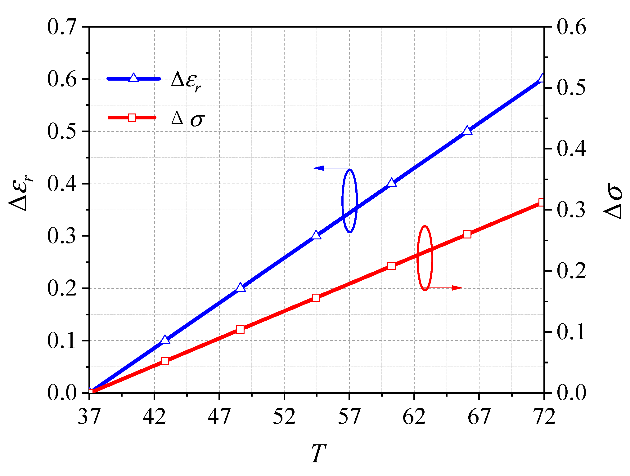
4.4. Influence of the Tissue Electrical Parameter Errors on the Microwave Penetration Effect of the Proposed Method

Temperature variations, tissue heterogeneity, and hydration levels all affect the electrical parameters of real human tissues, which in turn leads to changes in the characteristic impedance of each tissue. This also indicates that the homogeneous constant electrical parameter model of established human tissues differs from real human tissues, i.e., there is a tissue electrical parameter modeling error, which affects the matching effect and the increased penetration depth effect of a proposed method when it is used in real human tissues. To analyze the impact of tissue electrical parameter errors due to temperature variations, etc., on the penetration increase effect of the proposed method, we carried out a simulation validation using a single-layer human liver organ model as the research object. Specifically, we used a temperature variation as an example to study the impact of the resulting electrical parameter errors on the effectiveness of the proposed method.
In some common medical applications, the required temperature variations typically fall within a certain range. For example, the optimal heating temperature range for mild hyperthermia is 41–43 °C [23]. According to a temperature-dependent tissue electrical parameter model in the literature [24], within a range that included the above-specified interval (30–60 °C), the changes in the relative permittivity and conductivity of liver tissue ( ε r , σ ) were linearly related to the temperature change T ( ε r = 0.0172 T ,   σ = 0.00897 T ) at 915 MHz. Therefore, there was a definite linear correspondence between ε r and σ with temperature of σ / ε r = 0.52 . Taking the electrical parameters of the liver ( ε r = 46.764 ;   σ = 0.8612   S / m ) corresponding with T = 37 °C and f = 915 MHz as the nominal values, the change rule of the electrical parameter with temperature is shown in Figure 9.
We added different electrical parameter errors ( ε r ; σ ) to the liver tissues of Model 4 at 915 MHz and then performed full-wave simulations with the proposed Method 3 for these models after loading the two-layer matched medium. The microwave reflection coefficients and the penetration depths of the radiated microwaves in the liver tissue were calculated under different electrical parameter errors according to the simulation results, and the results are shown in Figure 10. The reflection coefficients were less than 0.05, and the differences are less than 0.005 compared with the reflection coefficients when there was no electrical parameter error, indicating that the method was able to reduce the reflection of the microwave energy at the interface better within the error range of ( 0.1 ε r 0.6 ;   0.052 σ 0.312 ) . Although the penetration depth of the proposed method was somewhat reduced ( d < 8.93   m m ) due to the electrical parameter error, there was still a 38% minimum increase compared with the corresponding microwave penetration depth of d = 20.515 mm without a matched layer, which indicated that the proposed method was still able to effectively improve the microwave penetration depth in the tissues under the above electrical parameter error range.

5. Conclusions

In this paper, a penetration depth increase method for radiated microwaves inside a lossy human body using a complex impedance match of the skin surface with a two-layered medium was proposed. The method avoided the impedance mismatch caused by the real impedance assumption on the skin surface of a lossy human body, and significantly reduced the microwave losses due to interfacial reflections. It could increase the energy transmitted through the skin surface into the human body to further increase the penetration depth of radiated microwaves in a lossy human body. The proposed two-layered medium match method was able to select a suitable medium for the matched Layer 1 by adjusting the relative permittivity of the matched Layer 2, which was more practical than the single-layer-medium optimized match method where the relative permittivity of the medium could not be adjusted. The simulation results showed that the reflection coefficient of the proposed two-layered medium match method was 0.015, and was reduced by 97.99 % and 97.19 % compared with those in the model with a no-matched layer and in the 1/4 wavelength medium match method for the real impedance model of a skin surface. Moreover, the proposed method increased the microwave penetration depth at the input power P i n = 0.5   W from d = 11.43   m m in the model without a matched layer to d = 21.01   m m ; the increase proportion was 83.81 % . The microwave penetration depth in the proposed method increased by 21.37 % compared with that of the 1/4 wavelength medium match method for the real impedance model of a skin surface. The applicability of the proposed method at different frequencies, using different human tissue models, and with different tissue electrical parameter errors as well as the effectiveness of the microwave penetration depth increase were analyzed and verified using full-wave simulations. These results indicate that the proposed method provides a good microwave penetration depth increase inside a lossy human body.

Author Contributions

Methodology, M.-L.M., D.Z., Y.W., F.L. and B.-Z.W.; Validation, Z.-J.H.; Writing—Original Draft, M.-L.M. and D.Z. All authors have read and agreed to the published version of the manuscript.

Funding

This work was funded in part by the University of Electronic Science and Technology of China “2021 Medical Oncology and Engineering Innovation Fund” project, No. ZYGX2021YGCX008, and the Radiation Oncology Key Laboratory of Sichuan Province.

Data Availability Statement

Data are contained within the article.

Conflicts of Interest

The authors declare no conflicts of interest.

References

  1. Alqadami, A.S.M.; Nguyen-Trong, N.; Stancombe, A.E.; Bialkowski, K.; Abbosh, A. Compact flexible wideband antenna for on-body electromagnetic medical diagnostic systems. IEEE Trans. Antennas Propag. 2020, 68, 8180–8185. [Google Scholar] [CrossRef]
  2. Misilmani, H.M.E.; Naous, T.A.; Khatib, S.K.A.; Kabalan, K.Y. A survey on antenna designs for breast cancer detection using microwave imaging. IEEE Access 2020, 8, 102570–102594. [Google Scholar] [CrossRef]
  3. Mobashsher, A.T.; Abbosh, A.M. Compact 3-D slot-loaded folded dipole antenna with unidirectional radiation and low impulse distortion for head imaging applications. IEEE Trans. Antennas Propag. 2016, 64, 3245–3250. [Google Scholar] [CrossRef]
  4. Mousavi, S.M.H.; Rezaeieh, S.A.; Darvazehban, A.; Mohammed, B.; Janani, A.S.; Abbosh, A.M. Tapered graded index lens antenna with enhanced penetration for near-field torso maging. IEEE Trans. Antennas Propag. 2023, 71, 78–88. [Google Scholar] [CrossRef]
  5. Zanoli, M.; Trefná, H.D. Iterative time-reversal for multi-frequency hyperthermia. Phys. Med. Biol. 2021, 66, 045027. [Google Scholar] [CrossRef]
  6. Baskaran, D.; Arunachalam, K. Design and experimental verification of 434 MHz phased array applicator for hyperthermia treatment of locally advanced breast cancer. IEEE Trans. Antennas Propag. 2021, 69, 1706–1715. [Google Scholar] [CrossRef]
  7. Geyikoğlu, M.D.; Çavuşoğlu, B. Microwave hyperthermia with X band flexible hyperthermia applicator for bone and joint cancer treatment. J. Electromagn. Waves Appl. 2022, 36, 1285–1297. [Google Scholar] [CrossRef]
  8. Baskaran, D.; Arunachalam, K. Implementation of thinned array synthesis in hyperthermia treatment planning of 434 MHz phased array breast applicator using genetic algorithm. IEEE J. Electromagn. RF Microw. Med. Biol. 2023, 7, 32–38. [Google Scholar] [CrossRef]
  9. Shah, I.A.; Zada, M.; Basir, A.; Yoo, H. Flexible metasurface-coupled efficient wireless Power transfer system for implantable devices. IEEE Trans. Microw. Theory Technol. 2024, 72, 2534–2547. [Google Scholar] [CrossRef]
  10. Shaw, T.; Samanta, G.; Mitra, D. Efficient wireless power transfer system for implantable medical devices using circular polarized antennas. IEEE Trans. Antennas Propag. 2021, 69, 4109–4122. [Google Scholar] [CrossRef]
  11. Iqbal, A.; Al-Hasan, M.; Mabrouk, I.B.; Basir, A.; Nedil, M.; Yoo, H. Biotelemetry and wireless powering of biomedical implants using a rectifier integrated self-diplexing implantable antenna. IEEE Trans. Microw. Theory Technol. 2021, 69, 3438–3451. [Google Scholar] [CrossRef]
  12. Zhang, K.; Zhang, Y.; Liu, X.; Guo, H.; Yang, X. Near-field wireless power transfer to deep-tissue implants for biomedical applications. IEEE Trans. Antennas Propag. 2020, 68, 1098–1106. [Google Scholar] [CrossRef]
  13. Iliopoulos, I.; Meo, S.D.; Zhadobov, M.; Pouliguen, P.; Potier, P.; Perregrini, L.; Sauleau, R.; Ettorre, M. Enhancement of penetration of millimeter waves by field focusing applied to breast cancer detection. IEEE Trans. Biomed. Eng. 2021, 68, 959–966. [Google Scholar] [CrossRef]
  14. Chen, Z.Y.; Gao, Y.M.; Du, M. Propagation characteristics of electromagnetic wave on multiple tissue interfaces in wireless deep implant communication. IET Microw. Antennas Propag. 2018, 12, 2034–2040. [Google Scholar] [CrossRef]
  15. Rodrigues, D.B.; Ellsworth, J.; Turner, P. Feasibility of heating brain tumors using a 915 MHz annular phased-array. IEEE Antennas Wirel. Propag. Lett. 2021, 20, 423–427. [Google Scholar] [CrossRef]
  16. Chavez-Santiago, R.; Khaleghi, A.; Balasingham, I. Matching layer for path loss reduction in ultra-wideband implant communications. In Proceedings of the 2014 36th Annual International Conference of the IEEE Engineering in Medicine and Biology Society (EMBC), Chicago, IL, USA, 26–30 August 2014. [Google Scholar]
  17. Yang, F.; Luo, J.; Xu, S.; Li, M. Design of artificial matching layers with arbitrary permittivity using a metasurface. IEEE Antennas Wireless Propag. Lett. 2018, 17, 1445–1448. [Google Scholar] [CrossRef]
  18. Cao, X.; Sato, H.; Xu, K.D.; Jiang, W.; Gong, S.; Chen, Q. A systematic method for efficient wireless powering to implantable biomedical devices. IEEE Trans. Antennas Propag. 2023, 71, 2745–2757. [Google Scholar] [CrossRef]
  19. Dobšíček Trefná, H.; Crezee, J.; Schmidt, M.; Marder, D.; Lamprecht, U.; Ehmann, M.; Nadobny, J.; Hartmann, J.; Lomax, N.; Abdel-Rahman, S.; et al. C Quality assurance guidelines for superficial hyperthermia clinical trials: II. Technical requirements for heating devices. Strahlenther. Onkol. 2017, 193, 351–366. [Google Scholar] [CrossRef]
  20. Andreuccetti, D.; Fossi, R.; Petrucci, C. An Internet Resource for the Calculation of Thedielectric Properties of Body Tissues in the Frequency Range 10 Hz–100GHz. IFAC-CNR, Florence (Italy). 1997. Available online: http://niremf.ifac.cnr.it/tissprop/ (accessed on 1 March 2024).
  21. Rana, J.N.; Muntaz, S.; Han, I.; Choi, E.H. Formation of reactive species via high power microwave induced DNA damage and promoted intrinsic pathway-mediated apoptosis in lung cancer cells: An in vitro investigation. Fundam. Res. 2024. [Google Scholar] [CrossRef]
  22. Li, J.; Wang, B.; Zhang, D.; Li, C.; Zhu, Y.; Zou, Y.; Chen, B.; Wu, T.; Wang, X. A preclinical system prototype for focused microwave breast hyperthermia guided by compressive thermoacoustic tomography. IEEE Trans. Biomed. Eng. 2021, 68, 2289–2300. [Google Scholar] [CrossRef]
  23. Bellizzi, G.G.; Sumser, K.; VilasBoas-Ribeiro, I.; Curto, S.; Drizdal, T.; van Rhoon, G.C.; Franckena, M.; Paulides, M.M. Standardization of patient modeling in hyperthermia simulation studies: Introducing the erasmus virtual patient repository. Int. J. Hyperth. 2020, 37, 608–616. [Google Scholar] [CrossRef] [PubMed]
  24. Deshazer, G.; Hagmann, M.; Merck, D.; Sebek, J.; Moore, K.B.; Prakash, P. Computational modeling of 915 MHz microwave ablation: Comparative assessment of temperature-dependent tissue dielectric models. Med. Phys. 2017, 44, 4859–4868. [Google Scholar] [CrossRef] [PubMed]
Figure 1. Illustration of the radiated microwaves penetrating into the human body from the skin surface by (a) a diffused beam, (b) a focused beam, and (c) a plane wave with a single-layered medium.
Electronics 13 03915 g001
Figure 2. The simplified layered model of the superficial human body.
Electronics 13 03915 g002
Figure 3. Real and complex impedance models of skin surfaces matched with different layered media: (a) real impedance model of a skin surface matched with a single-layered medium; (b) complex impedance model of a skin surface matched with a single-layered medium; (c) complex impedance model of a skin surface matched with a two-layered medium.
Electronics 13 03915 g003
Figure 4. Correspondence between different parameters of the two matched layers.
Electronics 13 03915 g004
Figure 5. The amplitude distribution of electric fields in three models: (a) no-matched layer; (b) Method 1; (c) Method 2; (d) Method 3.
Electronics 13 03915 g005
Figure 6. The intensity distribution of energy flow densities in three models: (a) no-matched layer; (b) Method 1; (c) Method 2; (d) Method 3.
Electronics 13 03915 g006
Figure 7. The amplitude distribution of electric fields on the z-axis.
Electronics 13 03915 g007
Figure 8. The energy flow density distribution on the z-axis.
Electronics 13 03915 g008
Figure 9. Temperature dependence of incremental electrical parameters of human liver tissue.
Electronics 13 03915 g009
Figure 10. Influence of electrical parameter errors of the tissue model on the microwave penetration effect of the proposed Method 3.
Electronics 13 03915 g010
Table 1. Electrical parameters of tissues [20].
Tissue f (GHz) ε r σ (S/m)
Skin2.4542.8531.5915
Fat2.455.28010.1045
Muscle2.4552.7291.7388
Table 2. The field distribution of different interfaces.
Model E x (V/m) S a v _ z (W/m2)
Air–SkinSkin–FatFat–MuscleAir–SkinSkin–FatFat–Muscle
No-matched layer133.84149.1448.19111.0863.4343.60
Method 1170.0289.4561.21181.11102.3670.35
Method 2200.97223.9472.35254.16143.0398.28
Method 3200.99223.9772.36251.05143.0598.32
Table 3. Penetration depth comparison.
Model d (mm)
P i n = 0.5 W * P i n = 2 W P i n = 8 W
No-matched layer11.4327.3642.7
Method 117.3132.6548
Method 22136.3151.52
Method 321.0136.3551.65
* P i n is the input power in the 61.225 mm × 61.225 mm area.
Table 4. The reflection coefficient and penetration depth comparison of different frequencies.
f (GHz) Γ d (mm)
No - Matched   Layer   ( Γ n o * )Method 3
( Γ M _ 3 * )
Γ n o Γ M 3 Γ n o No - Matched   Layer   ( d n o * )Method 3
( d M _ 3 * )
d M _ 3 d n o d n o
0.433 0.7400.01697.84%3454.4060%
0.9150.550.01098.18%35.9043.3720.81%
2.450.746 0.015 97.99%11.4321.01 83.81 %
3.50.860.11686.51%1.3615.841064.71%
* Γ n o is the reflection coefficient on the skin surface of the model without a matched layer. Γ M _ 3 is the reflection coefficient of Method 3. d n o is the microwave penetration depth in the model without a matched layer. d M _ 3 is the microwave penetration depth of Method 3.
Table 5. The reflection coefficient and penetration depth comparison of different human tissue models.
Human Tissue Model Γ d (mm)
No - Matched   Layer   ( Γ n o *)Method 3
( Γ M _ 3 *)
Γ n o Γ M 3 Γ n o No - Matched   Layer   ( d n o *)Method 3
( d M _ 3 *)
d M _ 3 d n o d n o
Model 10.746 0.015 97.99%11.4321.01 83.81 %
Model 20.60760.010798.24%15.9921.0631.71%
Model 30.74090.0095798.71%7.9819.57145.24%
Model 40.741780.030595.89%10.3318.3677.73%
* Γ n o is the reflection coefficient on the skin surface of the model without a matched layer. Γ M _ 3 is the reflection coefficient of Method 3. d n o is the microwave penetration depth of the model without a matched layer. d M _ 3 is the microwave penetration depth of Method 3.
Disclaimer/Publisher’s Note: The statements, opinions and data contained in all publications are solely those of the individual author(s) and contributor(s) and not of MDPI and/or the editor(s). MDPI and/or the editor(s) disclaim responsibility for any injury to people or property resulting from any ideas, methods, instructions or products referred to in the content.

