Article

Operation and Coordinated Energy Management in Multi-Microgrids for Improved and Resilient Distributed Energy Resource Integration in Power Systems

Energy Systems Research Laboratory, Department of Electrical and Computer Engineering, Florida International University, Miami, FL 33174, USA
*
Author to whom correspondence should be addressed.
Electronics 2024, 13(2), 358; https://doi.org/10.3390/electronics13020358
Submission received: 6 November 2023 / Revised: 11 January 2024 / Accepted: 13 January 2024 / Published: 15 January 2024

Abstract

:
Multi-microgrids (MMGs) revolutionize integrating and managing diverse distributed energy resources (DERs), significantly enhancing the overall efficiency of energy systems. Unlike traditional power systems, MMGs comprise interconnected microgrids that operate independently or collaboratively. This innovative concept adeptly addresses challenges posed by pulsed load effects, capitalizing on the cooperative nature of interconnected microgrids. A coordinated MMG system effectively redistributes and shares the impact of pulsed loads, mitigating voltage fluctuations and ensuring sustained system stability. The proposed cooperative MMG scheme optimizes power distribution and load prioritization, facilitating the seamless allocation of surplus energy from neighboring microgrids to meet sudden surges in demand. This study focuses on DC standalone multi-microgrid systems, showcasing their inherent adaptability, resilience, and operational efficiency in managing pulse, variable, and unpredictable generation deficits. Several experiments on a laboratory-scale DC multi-microgrid validate the system’s robust performance. Notably, transient current fluctuations during pulse loads are promptly stabilized through the effective collaboration of microgrids. Variable load experiments reveal distinct behaviors, shedding light on the profound influence of control strategies. This research reveals the transformative potential of MMGs in addressing energy challenges, with a particular focus on DC standalone multi-microgrid systems. The findings underscore the adaptability and resilience of the proposed cooperative scheme, marking a significant stride in the evolution of modern power systems.

1. Introduction

The introduction of distributed energy resources and the deployment of advanced metering, communication, and control technology at the distribution level has resulted in significant changes to the structure of traditional distribution networks in recent decades [1,2]. This progress has resulted in the birth of multi-microgrid systems, distinguished by incredible speed and more controllability and dependability. These multi-microgrid systems support a wide range of energy resources, from fixed and dispatchable power sources to probabilistic and intermittent distributed generators (DGs), and serve a wide range of energy consumers, including fixed, non-controllable loads as well as hourly and probabilistic variable loads. This dynamic composition has highlighted the critical importance of good energy management tactics in multi-microgrid systems [3]. A microgrid is a localized, small-scale power system integrating several energy generation, storage, and load control techniques. It provides a dependable, cost-effective, and long-lasting energy supply to a specific consumer, building, or industry and operates attached to or apart from the electrical grid. Because of the need to reduce dependency on centralized power networks and growing concerns about energy security, microgrids are becoming more and more popular. Microgrids may provide a renewable energy balance by combining various renewable energy sources [4]. Microgrids can be AC, DC, or hybrid AC/DC systems, making the appropriate architecture very prominent depending on the needs and requirements requested [5]. However, the use of microgrids faces several challenges, such as the unpredictable nature of renewable resource generation, disruptions in the transmission lines, interruptions in the equipment connecting microgrids (MGs) and the distribution system, and the risk of accidental power failures arising from specific load demand [6,7,8]. For instance, a heavy pulse load or load with a large startup current can cause a significant issue regarding the instability of a microgrid [9]. The high short-time current behavior not only requires the use of higher-rated power components but also has the potential to cause voltage and frequency shifts throughout the whole microgrid. These weak points can be very harmful in the case of the DC Microgrid because of the lack of the system’s infinite bus (grid), which generally acts as a stabilizing reference point for voltage and frequency regulation. The concept of a multi-microgrid system offers several benefits and solutions, emphasizing improving the robustness and dependability of the more significant power infrastructure. A MMG system ensures that cases of power outages or imbalances inside one microgrid due to any of the previously outlined reasons are handled with prompt assistance from other microgrids, utilizing its capacity to provide smooth power distribution and equilibrium maintenance across the linked microgrids. This collaborative approach successfully reduces interruptions and ensures a constant and reliable power supply, assuring the uninterrupted delivery of electricity to end customers.
Numerous studies have been conducted on the operation scheduling approaches of MMGs. In [10], a cooperative energy and reserve scheduling paradigm for multi-microgrid operation has been presented. The suggested technique enhances operational efficiency and saves costs by coordinating energy generation and storage across linked microgrids. In [11], the authors present real-time energy management of many microgrids. The study provides a stochastic spatiotemporal decomposition method in which uncertainty has been resolved via maximizing resource allocation through considering geographical and temporal aspects. Another study [12] proposes a secure, decentralized transactive energy management system that accounts for probable misbehaviors for numerous interconnected microgrids. The authors conclude that the suggested plan reduces the risks of hostile or unauthorized activity by implementing robust, strong security measures and monitoring systems. A separate study [13] focuses on the coordinated management of energy across networked microgrids inside distribution systems. The study examines strategies for enhancing energy production, consumption, and storage across numerous interconnected microgrids. It attempts to improve overall system efficiency, dependability, and grid resilience by applying a coordinated energy management method. Further research [14] offers a unique distributed economic model predictive control strategy for the collaborative management of multi-microgrids, successfully managing supply and demand uncertainties, lowering operating costs, and assuring supply-demand balance. Several studies have analyzed the resilience of a distribution network with multi-microgrids (MMGs) [15,16,17,18,19,20,21].
A key challenge for DC standalone systems (e.g., microgrids) is effectively managing specific types of loads, particularly high-demand loads. This challenge is compounded by the fact that these systems rely primarily on renewable energy sources, which are inherently unreliable due to their intermittent nature.
Several scholars have investigated the effects of integrating pulsed loads in standalone power systems. This research can be categorized into three main categories: (1) using energy storage systems, (2) analyzing how pulsed loads affect power systems, and (3) minimizing the adverse effects of pulsed loads. The works in the first category state that there are multiple types of energy storage, such as batteries, ultracapacitors, and flywheels. However, the characteristics of each one pose a challenge to accommodating pulse loads; batteries have high energy density but need more power density. In contrast, ultracapacitors and flywheels have opposite characteristics [22]. Combining both categories of ESS has been an area of study—for instance, hybrid battery-ultracapacitor systems [23].
In the second category, the impacts of pulsed load power and interval time on system frequency and voltage have been investigated in [24]. In addition, several studies have investigated pulsed loads’ effects on shipboards, such as [25], in which the authors highlight the importance of energy storage systems in preserving stability. Multiple studies have compared the impact of pulsed loads in power systems [25,26,27].
The objective of research studies is to minimize the impact of pulsed loads on power systems. In theory, research such as [28] analyzes the dynamics of pulse loads in marine integrated power systems (IPSs) by employing a novel approach known as the millisecond-time-scale-based state-space averaging mode (MTS-SSAM). This approach acknowledges the variability and irregularity in the switching periods of pulsed loads and adapts to them by operating on a millisecond time scale. Another paper [29] analyzes the challenge of meeting the peak power demands of pulsed power loads such as radar and beam weapons, which often exceed the generator’s capacity. This paper proposes a sizing process for hybrid energy storage systems based on Non-Dominated Sorting Genetic Algorithm and a decision-making method to achieve the most suitable result.
These research papers have primarily focused on integrating energy storage systems to manage the high demand of pulse load, microgrid operations, and optimizing economic aspects. However, numerous issues affect battery-based energy storage systems, most notably their inability to withstand fluctuating peak power demands, frequently decreasing battery life. The size of the battery bank can be increased as a standard solution, but doing so presents challenges like higher costs, thermal issues, and cell imbalances. Hybrid energy storage systems (battery-supercapacitor systems) can provide viable solutions, especially for enhancing efficiency and power quality. Furthermore, those systems prove highly practical for various contexts, including shipboard power systems, aircraft systems, and electric vehicles. However, there are many issues with hybrid energy storage implementation. Implementing a hybrid energy storage system that includes batteries and supercapacitors might require more work regarding control and management. The necessity for additional control circuitry and switching methods for managing the two energy storage technologies can increase system complexity and cost, which may only sometimes be justified by the benefits achieved in some applications.
A networked microgrid system is an excellent option for providing reliable power with high efficiency in various power systems that use sustainable energy sources. Unlike a single microgrid with limited capabilities or a conventional power grid with centralized vulnerabilities, the networked microgrid excels in decentralized, resilient power distribution across linked microgrids, ensuring uninterrupted supply despite pulse load-induced outages. These systems (i.e., multi-microgrids) may distribute pulse load demands effectively across linked microgrids, eliminating overloads and ensuring an uninterrupted power supply. Microgrid energy storage devices store extra energy during periods of low demand and swiftly release it when pulse loads evolve. Table 1 shows a comparison between the proposed approach and other similar power systems.
Furthermore, comprehensive control and monitoring capabilities allow real-time load balancing and planned management, which reduces stress on individual microgrids. Networked microgrids’ resilience enables continuous power supply even in the face of pulse load-induced outages, making them an excellent option for various applications, from industrial facilities to military applications.
The main research contributions of this paper are as follows:
  • The networked microgrid was studied and tested under different scenarios in both simulation and experiment.
  • The development and experimental testing of an energy management system to maintain a networked microgrid’s continuous operation under various renewable energy and load conditions, depending on which energy devices are available and how much power the load needs.
  • The proposed system architecture provides high performance against pulse loads and variable loads.
The rest of this paper is organized as follows: Section 2 describes the system architecture and component modeling; Section 3 shows the simulation and operation results under different scenarios; Section 4 describes the hardware setup and discusses the experimental test results; and finally, conclusions are given in Section 5.

2. System Architecture and Modeling

This section explains the structure of MMGs, general concepts of the energy management technique, and details of microgrid components.

2.1. Proposed Multi-Microgrid System Structure

The system addressed in this research comprises two DC microgrids supplying different load profiles, as shown in Figure 1. Each microgrid has several components, including a renewable energy source (RES) unit, energy storage (ES) unit, and multiple resistive load units connected. The RES and ES units are connected to the microgrid bus through a bidirectional DC/DC converter (BDC), and the loads are connected directly to Microgrid buses 1 and 2. A microgrid central controller (MCC) is responsible for the operation and coordination of the various components. The primary objective of the MCC is to ensure the optimal utilization of available resources, mainly managing the flow of energy between the RES unit, ES unit, and loads. These two microgrids are also connected, allowing for power exchange as necessary. A DC link facilitates this interconnection, allowing for smooth power transfer from one microgrid to the other. The DC link also allows for synchronization and voltage management, ensuring dependable and efficient power exchange.
In addition to their load profiles, both microgrids collaborate to solve an essential component: a pulse load coupled to the DC link. This pulse load poses a distinct problem due to its sudden and intermittent energy consumption. When such high-demand situations occur, the microgrids collaborate to provide a reliable, quick response. The coordinated effort includes effectively combining excess energy resources and maximizing the usage of energy storage devices to address any supply-demand imbalances.
A centralized energy management system coordinates the collaboration between the two microgrids. It directs resource allocation, monitors energy flow, and manages responses to pulse load events. This coordination enhances system adaptability and reliability, ensuring efficient power delivery to meet diverse load requirements.

2.2. Microgrid System

2.2.1. PV System Model

The photovoltaic system regulates its output current depending on sun irradiation and module temperature. Panel temperature, T p , is determined using a dynamic equation based on the energy balance [30].
d T p ( t ) d t = 1 H P ( G t Q r a d t P e l ( t ) )
H P (with H P > 0) represents the heat capacity, whereas G represents the amount of absorbed radiation. Additionally, Q r a d   indicates the radiation heat transfer, and P e l refers to the electric power established. To compute the voltage of the PV module, we apply a one-diode model as described in [31].
V p v t = V d t I p v t R s
The current I p v is calculated as follows, taking into consideration the voltage across the diode:
I p v ( t ) = I p h t I 0 t e x p V d t V t t 1 V d t R s h
V t stands for the terminal voltage, I 0 for the diode reverse saturation current, R s h for the shunt resistance, and I p h for the current under irradiation.

2.2.2. Battery System Model

The battery model discussed here is based on a general concept first presented in [32]. It is shown here as a perfect DC source connected in series with a controlled internal resistance called R B . The state-of-charge (SOC) of the battery is a crucial element in a nonlinear equation used to calculate the battery’s no-load voltage, abbreviated as E B . The following is the equation:
E B = E 0 K 1 S O C + A B Q ( 1 S O C )
In this context, E 0 stands for the battery’s constant voltage, K for its polarization voltage, Q for its ampere-hour capacity, and A and B for its charge and discharge characteristics. This model may be customized by changing the parameters A, B, and K to match the discharge characteristics of a particular battery type.

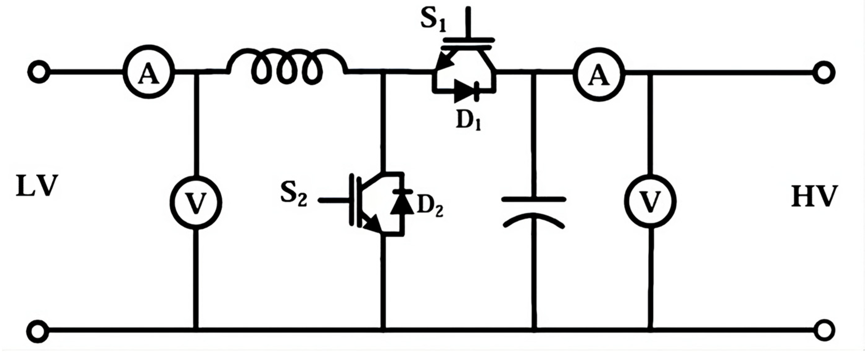
2.2.3. Bidirectional DC-DC Converter

The converter presented in Figure 2 offers two distinct operational modes: boost and buck. The boost mode enables controlled energy transfer from the low-voltage (LV) terminal to the high-voltage (HV) terminal by activating IGBT S2. When IGBT S2 is in the “on” state during the boost mode, it initiates a precise sequence of operations. This includes charging inductor L and directing energy discharge from capacitor C through the HV terminal.
On the other hand, when IGBT S2 transitions to the “off” state, it redirects the current path through inductor L and the freewheeling diode D1. This redirection efficiently charges capacitor C and facilitates energy transfer to the HV terminal.
In the buck mode of operation, energy transfer occurs from the high-voltage (HV) terminal to the low-voltage (LV) terminal through the controlled activation of IGBT S1, modulated via a specific duty cycle. When IGBT S1 is in the “on” state during the buck mode, it initiates a regulated process. In this phase, the input current from the HV terminal is directed through the filter inductor L, effectively facilitating energy transfer to the LV terminal.
A strategic occurrence transpires upon the transition of IGBT S1 to the “off” state. The stored energy in the inductor triggers the conduction of freewheeling diode D2. Consequently, the inductor’s current continues to flow through both inductor L and diode D2. During this phase, the inductor’s current gradually diminishes until IGBT S1 is activated again in the subsequent cycle.

2.2.4. Microgrid Energy Management System

Algorithm 1 initiates by assessing the available power generation (Pres) and the load demand (PLoad) within a microgrid. It calculates the energy surplus or deficit (NetExtra) by subtracting the load demand from the available power generation. If there is a surplus, the algorithm computes the amount of surplus energy that can be effectively stored in the energy storage system (ESS) and proceeds to charge the ESS. Conversely, in the case of a deficit, it calculates the necessary energy discharge from the ESS to meet the load demand, ensuring that the ESS discharges only up to its capacity. The algorithm then recalculates the available power (PAvail) while considering the ESS’s charge or discharge, optimizing energy management, and effectively balancing energy supply and demand within the microgrid before concluding its execution.
Algorithm 1: Microgrid EMS
Initialize Pres (Power Gen), Pload (Load Demand)
Calculate NetExtra = Pres − Pload
If NetExtra > 0:
   Calculate Charge = min(NetExtra, ESS Capacity)
   Charge ESS with Calculated energy
If NetExtra < 0
   Calculate Discharge = min(-NetExtra, ESS Capacity)
   Discharge ESS to meet load demand
Calculate Pavai considering ESS charge or discharge
End

2.3. Multi-Microgrid Operation

The energy management system in the multi-microgrid system is structured into two distinct parts, each comprising two modes to address varying operational scenarios:
External Load Disconnected:
  • Mode 1: When the generated power from the microgrids’ PV systems surpasses the local load demand of the two microgrids, resulting in a positive net generation, the system initiates Mode 1. Within this mode, it delves into each microgrid’s internal generation and load profiles. A positive balance within a microgrid ensures that each load receives the required power, and any remaining surplus is sent into the energy storage system (ESS). If there is still an excess of power after ESS charging, the PV systems transition into a Proportional-Integral (PI) control mode instead of Maximum Power Point Tracking (MPPT).
  • Mode 2: When the generated power from the microgrids’ PV systems falls short of meeting the local load demand of the two microgrids, resulting in a negative net generation, Mode 2 is activated. Within this mode, the system carefully evaluates Microgrid 1 and Microgrid 2. If one microgrid experiences a positive balance of generation and load, it shares power resources with the other microgrid, helping it meet its demand. However, if both microgrids are in deficit, the system initiates the disconnection of a secondary load in Microgrid 2 to restore power balance and ensure system stability.
External Load connected:
  • Mode 3: In this mode, when the generated power from the microgrids’ PV systems exceeds the local load demand plus the external load of the two microgrids, the system optimally allocates power resources. It first evaluates the power generation and local load within each microgrid, ensuring that excess power, if any, is appropriately distributed to meet local load requirements. Any surplus energy beyond local needs is then directed to supply the external load. The power source in this mode is a combination of PV and energy storage systems (ESSs), allowing for efficient energy sharing and utilization.
  • Mode 4: When the generated power from the microgrids’ PV systems falls short of meeting the local load and external load demands for the two microgrids, the system employs a strategy to balance the power deficit. It assesses each microgrid’s generation and load profiles, identifying which has a surplus and which faces a deficit. If one microgrid generates excess power, it shares it with the other microgrid to support its load demands, including the external load. In cases where both microgrids experience power deficits, the system initiates the disconnection of a secondary load in Microgrid 2 to ensure that the power supply remains stable.

3. Simulation and Operation Results

Simulation Results

In order to test the performance of the proposed system for managing power transfer between interconnected DC microgrids, several case scenarios were adopted:
External Pulse load connected:
In this scenario, an effective DC multi-microgrid system composed of two distinct microgrids coupled via a DC connection and governed by a microgrid central controller (MCC) reacts to an external pulse demand ranging from 50 W to 180 W, as shown in Figure 3. For instance, when the pulse load spikes at t = 3 s, both microgrids quickly respond by increasing their power production via renewable energy sources and energy storage units to satisfy the increased demand. In addition, a transient voltage fluctuation in the DC bus indicates the dynamic reaction of the system.
This scenario demonstrates the efficacy of the microgrids’ combined effort, coordinated by the MCC, in delivering a dependable, quick response to intermittent high-demand conditions, assuring a power supply that accommodates various loads. Both microgrids have a local load that needs to be supplied and then delivered the power requested from the external load based on the power status of the microgrid. Battery current graphs in Figure 4 show rapid surges in Microgrid 1 and Microgrid 2 at every load increase in response to the external pulse load, indicating instantaneous energy discharge to meet the demand. At the same time, the DC bus voltage at both microgrids remains constant at the desired level.
External variable load connected
The system adjusts to a more constant load pattern when changing from the prior pulse load scenario to a variable load profile. Microgrids of renewable energy sources (RES) and energy storage (ES) units synchronize their power generation with changing load needs while considering each microgrid’s available power after meeting its local demand. Microgrids may prioritize stored energy and optimize RES generation during low-demand times. When the load rises, they respond by increasing RES generation while successfully managing energy storage, as illustrated in Figure 5. This coordinated reaction provides balanced and efficient power distribution, showing the flexibility and coordination between the microgrids in tolerating fluctuating yet predictable load situations while considering their local load needs.
The fluctuations observed in the load change figure can be attributed to the dynamic nature of the multi-microgrid system. As the system adapts to varying load profiles, RES units adjust their power output, and ES units discharge or store energy to meet changing demands as demonstrated in Figure 6, introducing temporary power variations.
The coordinated responses between microgrids and the system’s central controller led to these fluctuations, demonstrating the system’s ability to adapt to dynamic load conditions while optimizing resource utilization efficiently, ultimately ensuring reliable and cost-effective power supply.
Generation deficit
This distinctive situation is aptly depicted in Figure 7, which illustrates the unfolding vital events. At t = 3.5 s, a critical moment occurs as Microgrid 2 grapples with an issue that severely impacts its ability to generate power. In response, the loads within Microgrid 2 depend entirely on Microgrid 1 to meet their power demands. Furthermore, during this period, an external microgrid input of a constant 36 W is introduced into the system. This added source acts as a critical lifeline to Microgrid 2, bridging the gap created by the deficit in its power generation. At t = 7 s, another significant development unfolds as a load change occurs within Microgrid 2. This change involves the disconnection of its second load, leading to observable shifts in the power dynamics.
Upon closer examination, it becomes evident that the disconnection of the load within Microgrid 2 results in a decrease in power generation from Microgrid 1. Simultaneously, Microgrid 2 experiences a notable increase in available power, although it remains in the negative range. This negative value signifies that Microgrid 2 is still receiving power, even though it must rely on external sources to meet its energy requirements. Figure 8 illustrates ES units discharge or store energy to meet changing demands as demonstrated.
This scenario underscores the importance of the interconnected multi-microgrid system in ensuring the continuity of power supply, even in the face of unexpected disruptions and deficits in localized power generation. It showcases the system’s ability to balance power distribution seamlessly and to adapt swiftly to maintain stable and efficient operations, emphasizing its intrinsic resilience and capacity to manage complex energy scenarios effectively.

4. Hardware and Experimental Test Results

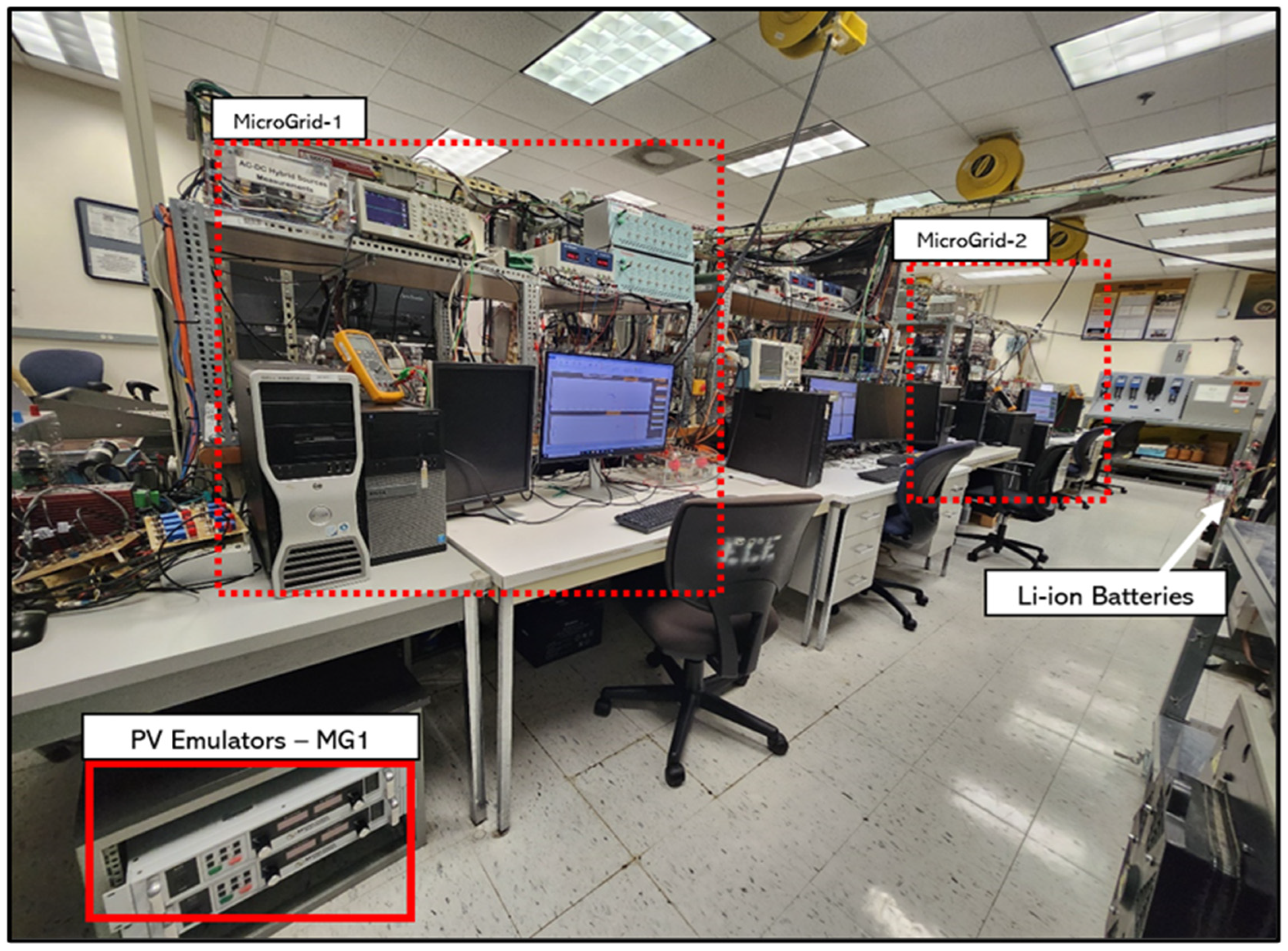
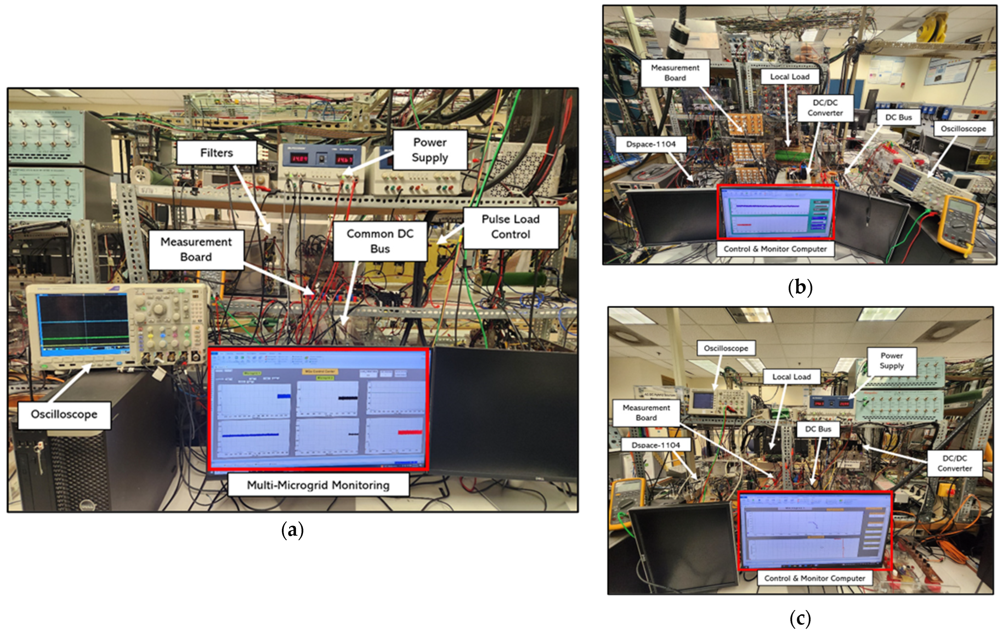
4.1. Experimental Setup

The proposed system was evaluated using a laboratory-scale DC multi-microgrid testbed. As depicted in Figure 9 and Figure 10, the testbed comprises two microgrids interconnected through a common DC bus, and an external programmable load has been introduced for a comprehensive evaluation. Each microgrid (MG) contains photovoltaic (PV) systems and lithium-ion batteries (LIBs) for energy storage. Through using DC boost converters to implement Maximum Power Point Tracking (MPPT) for each PV control, the PV systems are fine-tuned for efficient power generation.

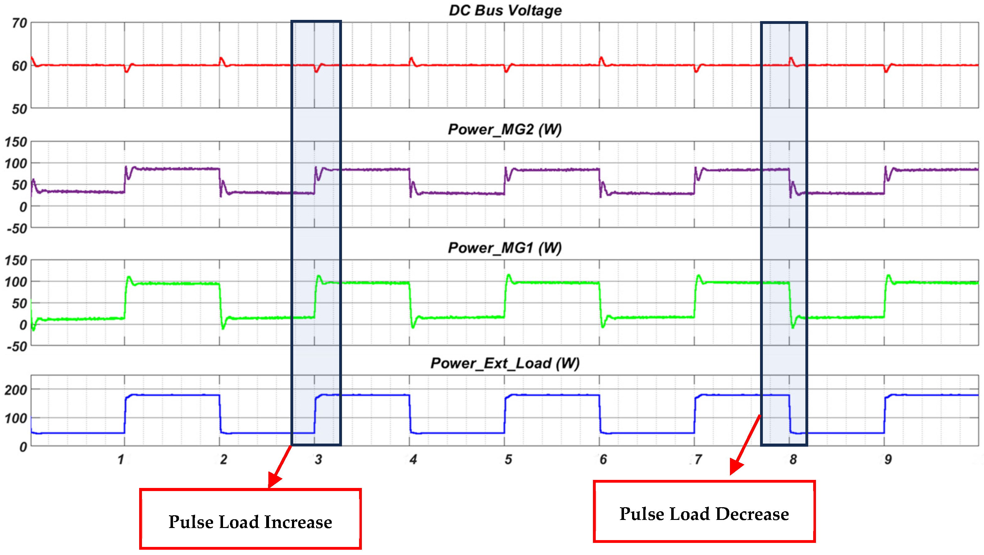
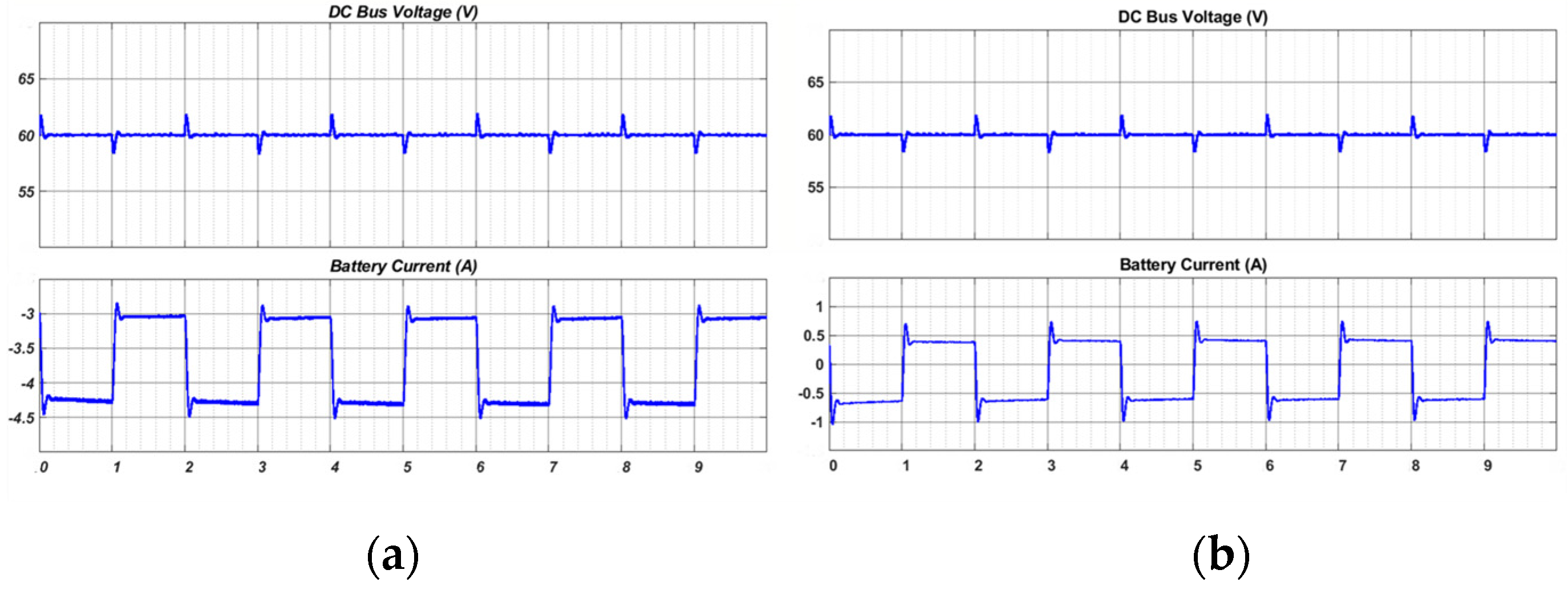
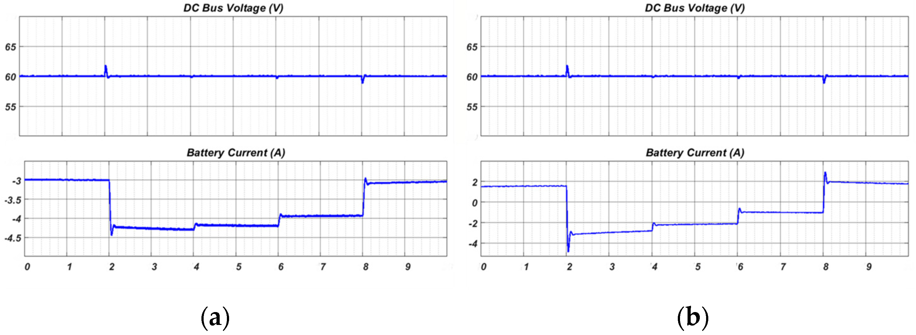
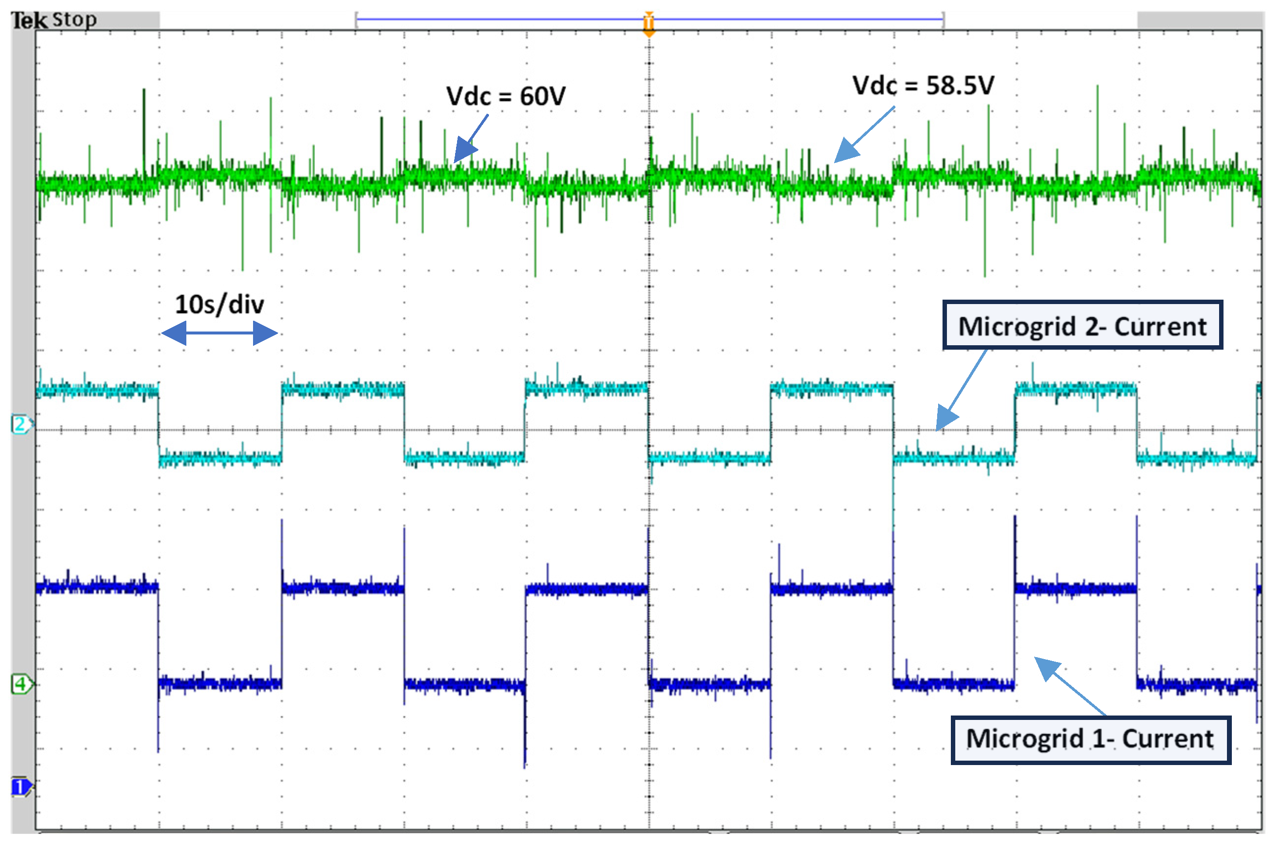
4.2. Scenario 1: External Pulse Load

The control system for the hybrid DC microgrid has been developed using the Matlab/Simulink R2022a software platform and is operated with the dSPACE 1104 real-time interface. Furthermore, the duty ratio, magnitude, and frequency of the pulsed load are precisely regulated by implementing the dSPACE 1104 board. Within this section, the investigation focuses on analyzing the influence of the pulsed power load and its specific characteristics on the overall performance of the multi-microgrid system. Microgrid 1 local load drew 180 watts of power during this experimental setup, while Microgrid 2 loads 1 and 2 consistently drew 110 watts and 120 watts of power, respectively. Simultaneously, a pulsed load with a magnitude of 360 watts, a 50% duty ratio, and a frequency of 0.1 Hz was applied. Figure 11 illustrates the DC bus voltage and the current drawn by the pulsed load from each microgrid.
Observable from the results, the voltage of the shared DC bus was initially at 60 V before the pulsed load was initiated. After the pulse load, the bus voltage experienced a decline to 58.5 V. The current injected from Microgrid 1 is 2.48 A, while the current from Microgrid 2 is 0.52 A. It can be noticed that a slight fluctuation in the current of MG1 during the pulse load occurrence is attributed to the dynamic response of the microgrid system. This is justified by the fact that when a sudden pulsed load is applied, MG1 and MG2 prioritize their local loads, affecting power distribution during load fluctuations. Load prioritization can result in divergent responses to pulse loads.

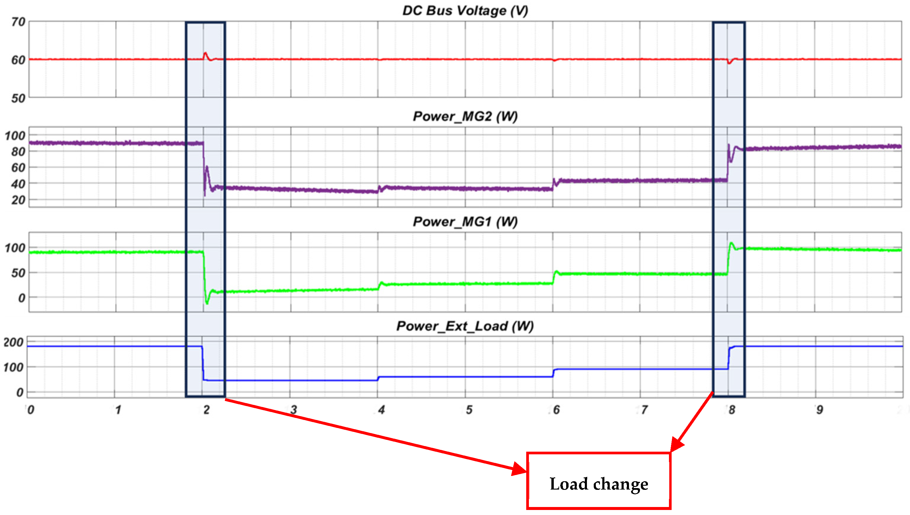
4.3. Scenario 2: External Variable Load

Another scenario was tested in this setup, which is a variable load where power demand changes gradually over an extended period. The objective of this scenario was to evaluate the ability of the multi-microgrid system to respond to changing load circumstances without causing sudden and disruptive effects on the system’s stability and performance. The variable load scenario contributes to a more thorough examination of the microgrid’s adaptability to various load types, complementing the findings obtained through the pulse load.
The external load demand in this scenario starts from 360 watts, which is the highest value. It can reach 80 watts as the lowest value with successive changes to investigate and evaluate the multi-microgrid response. We notice clearly from Figure 12 that the DC bus voltage fluctuates, especially during significant changes. At high resistance values, we see a slight decrease from the desired value to a lower value of 58.5 V. The currents from the two microgrids show that the first responds strongly due to the significant energy power it has from the PV solar system. The current in the second microgrid changes from positive to negative if the power is insufficient for the local load. The first microgrid can contribute to meeting the load of the second.

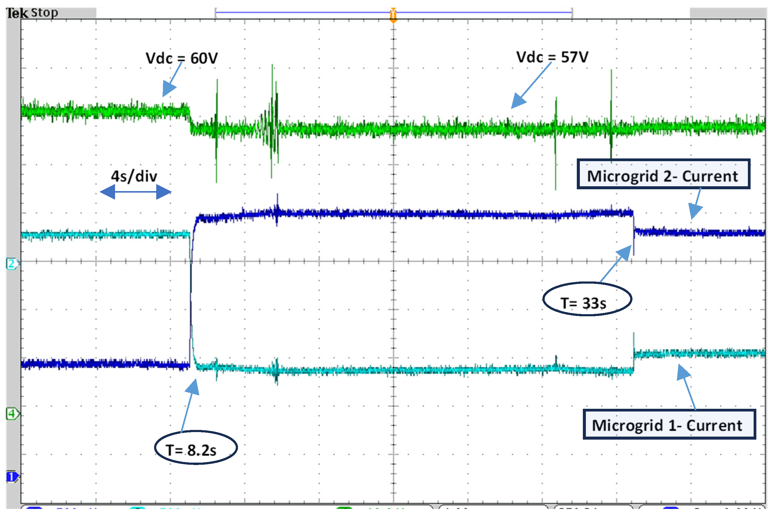
4.4. Scenario 3: Generation Deficit

In this scenario, a critical event is introduced to test the robustness of the multi-microgrid system when faced with a sudden power generation deficit. The system initially operates under normal conditions, with both Microgrid 1 and Microgrid 2 functioning correctly. However, at a specific time during the experiment, the power generation of Microgrid 2 experienced a complete shutdown, creating an immediate generation deficit.
The Investigation aims to analyze ”ow M’crogrid 1 responds to this deficit and whether it can effectively handle the additional load to maintain system stability. This scenario is significant because it simulates a real-world situation where a microgrid may need to compensate for an unexpected loss of power generation. Microgrid 1’s local load draws 180 watts of power during this setup, while Microgrid 2’s loads 1 and 2 remain at 110 watts and 120 watts, respectively. At t = 8.2 s, Microgrid 2’s power generation is abruptly disconnected. Figure 13 illustrates the DC microgrid bus voltage changes and the currents drawn from Microgrid 1 and 2 in response to the generation deficit. From the results, as Microgrid 2’s generation abruptly shuts down, Microgrid 1 experiences an increase in its local load from 180 to 450 watts due to the additional load from Microgrid 2 and the external load. The DC microgrid bus voltage initially drops but stabilizes as Microgrid 1’s control system responds to the increased load demand by adjusting its power output. The current injected from Microgrid 1 significantly increases to provide the required power, demonstrating the ability of the microgrid to adapt to changing conditions and handle a generation deficit without compromising system stability.
This scenario highlights the multi-microgrid system’s resilience and capacity to manage unexpected events, ensuring uninterrupted power supply to critical loads during a power generation deficit. It underscores the importance of a well-designed control system that can respond effectively to dynamic changes and maintain the reliability and functionality of the microgrid.

5. Conclusions

This paper presented an intensive study on DC standalone multi-microgrid systems and their characteristics and operational dynamics. Several scenarios were conducted, including a programmable pulse load, variable load, and generation deficit. The proposed system architecture, consisting of interconnected DC microgrids, renewable energy sources, and energy storage units, demonstrates its adaptability, resilience, and efficiency in managing various load scenarios. The experiments on a laboratory-scale DC multi-microgrid testbed validate the system’s performance in responding to external pulse loads, variable loads, and unexpected generation deficits.
The results show that MG1 exhibited some fluctuations in its current during pulsed load conditions, especially at the onset of the pulse load. This behavior can be attributed to the system’s dynamic response to the sudden application of a pulse load. Pulsed loads are characterized by their rapid power demand changes, which require a quick adaptation of the microgrid system. MG1 exhibited these transient current fluctuations when faced with the initial impact of the pulse load. However, MG1 and MG2 effectively collaborated to supply the external pulse load and maintain overall system stability.
Moreover, the microgrids’ responses were scrutinized in a separate experiment involving variable load conditions. MG1 and MG2 showcased contrasting behaviors, highlighting the influence of control strategies, component specifications, and load distribution in shaping system dynamics. Other than this, these systems play a critical role in the case of a generation deficit. Microgrid 1 successfully adapts to handle the additional load, stabilizing the system. This highlights the system’s robustness in managing unexpected events and underscores the importance of effective control systems in maintaining reliability.
Overall, this research contributes significantly to the advancement of cooperative multi-microgrid networks, offering an efficient and sustainable solution for managing the growing penetration of DERs and enhancing the resilience of modern power systems. These findings provide valuable insights into the practical implementation of multi-microgrid systems, particularly in addressing pulsed loads and generation deficits. Future studies could explore optimizing control strategies, enhancing system efficiency, and investigating scalability for broader applications in diverse energy management scenarios.

Author Contributions

Conceptualization, A.A. and O.A.M.; methodology, A.A. and O.A.M.; software, A.A.; validation, A.A.; writing—original draft preparation, A.A.; writing—review and editing, A.A. and O.M; visualization, A.A.; supervision, O.A.M.; project administration, O.A.M. All authors have read and agreed to the published version of the manuscript.

Funding

This research received no external funding.

Data Availability Statement

Data is contained within the article.

Conflicts of Interest

The authors declare no conflict of interest.

References

  1. Mo, X.; Zhu, J.; Chen, J.; Guo, Y.; Xia, Y.; Liu, M. A Stochastic Spatiotemporal Decomposition Decision-Making Approach for Real-Time Dynamic Energy Management of Multi-Microgrids. IEEE Trans. Sustain. Energy 2020, 12, 821–833. [Google Scholar] [CrossRef]
  2. Liu, Y.; Gooi, H.B.; Li, Y.; Xin, H.; Ye, J. A secure distributed transactive energy management scheme for multiple interconnected microgrids considering misbehaviors. IEEE Trans. Smart Grid 2019, 10, 5975–5986. [Google Scholar] [CrossRef]
  3. Peddakapu, K.; Srinivasarao, P.; Mohamed, M.R.; Arya, Y.; Kishore, D.J.K. Stabilization of frequency in Multi-Microgrid system using barnacle mating Optimizer-based cascade controllers. Sustain. Energy Technol. Assess. 2022, 54, 102823. [Google Scholar] [CrossRef]
  4. Karimi, H.; Jadid, S.; Makui, A. Stochastic energy scheduling of multi-microgrid systems considering independence performance index and energy storage systems. J. Energy Storage 2021, 33, 102083. [Google Scholar] [CrossRef]
  5. Chi, Y.; Xu, Y.; Hu, C.; Feng, S. A State-of-the-Art Literature Survey of Power Distribution System Resilience Assessment. In Proceedings of the 2018 IEEE Power & Energy Society General Meeting (PESGM), Portland, OR, USA, 5–10 August 2018. [Google Scholar]
  6. Saeed, M.H.; Fangzong, W.; Kalwar, B.A.; Iqbal, S. A Review on Microgrids’ Challenges Perspectives. IEEE Access 2021, 9, 166502–166517. [Google Scholar] [CrossRef]
  7. Vafamand, N.; Mardani, M.M.; Khooban, M.H.; Blaabjerg, F.; Boudjadar, J. Pulsed power load effect mitigation in DC shipboard microgrids: A constrained modelpredictive approach. IET Power Electron. 2019, 12, 2155–2160. [Google Scholar] [CrossRef]
  8. Aghmadi, A.; Hussein, H.; Polara, K.H.; Mohammed, O. A Comprehensive Review of Architecture, Communication, and Cybersecurity in Networked Microgrid Systems. Inventions 2023, 8, 84. [Google Scholar] [CrossRef]
  9. Horowitz, K.A.; Peterson, Z.; Coddington, M.; Ding, F.; Sigrin, B.; Saleem, D.; Baldwin, S.; Lydic, B.; Stanfield, S.; Enbar, N.; et al. An Overview of Distributed Energy Resource (DER) Interconnection: Current Practices and Emerging Solutions. 2019. Available online: www.nrel.gov/publications (accessed on 2 October 2023).
  10. Bullich-Massagué, E.; Díaz-González, F.; Aragüés-Peñalba, M.; Girbau-Llistuella, F.; Olivella-Rosell, P.; Sumper, A. Microgrid clustering architectures. Appl. Energy 2018, 212, 340–361. [Google Scholar] [CrossRef]
  11. Kou, P.; Liang, D.; Gao, L. Distributed EMPC of multiple microgrids for coordinated stochastic energy management. Appl. Energy 2017, 185, 939–952. [Google Scholar] [CrossRef]
  12. Moghateli, F.; Taher, S.A.; Karimi, A.; Shahidehpour, M. Multi-objective design method for construction of multi-microgrid systems in active distribution networks. IET Smart Grid 2020, 3, 331–341. [Google Scholar] [CrossRef]
  13. Babaiahgari, B.; Jeong, Y.; Park, J.-D. Stability Analysis for Interconnected DC Microgrids with Constant Power Loads. In Proceedings of the 2019 IEEE Energy Conversion Congress and Exposition (ECCE), Baltimore, MD, USA, 29 September–3 October 2019. [Google Scholar]
  14. Zhang, B.; Li, Q.; Wang, L.; Feng, W. Robust optimization for energy transactions in multi-microgrids under uncertainty. Appl. Energy 2018, 217, 346–360. [Google Scholar] [CrossRef]
  15. Arefifar, S.A.; Ordonez, M.; Mohamed, Y.A.R.I. Energy Management in Multi-Microgrid Systems—Development and Assessment. IEEE Trans. Power Syst. 2016, 32, 910–922. [Google Scholar] [CrossRef]
  16. Gao, H.; Liu, J.; Wang, L.; Wei, Z. Decentralized Energy Management for Networked Microgrids in Future Distribution Systems. IEEE Trans. Power Syst. 2018, 33, 3599–3610. [Google Scholar] [CrossRef]
  17. Arefifar, S.A.; Mohamed, Y.A.R.I.; El-Fouly, T. Optimized multiple microgrid-based clustering of active distribution systems considering communication and control requirements. IEEE Trans. Ind. Electron. 2015, 62, 711–723. [Google Scholar] [CrossRef]
  18. Jiang, W.; Yang, K.; Yang, J.; Mao, R.; Xue, N.; Zhuo, Z. A Multiagent-Based Hierarchical Energy Management Strategy for Maximization of Renewable Energy Consumption in Interconnected Multi-Microgrids. IEEE Access 2019, 7, 169931–169945. [Google Scholar] [CrossRef]
  19. Wang, Z.; Chen, B.; Wang, J.; Kim, J. Decentralized Energy Management System for Networked Microgrids in Grid-Connected and Islanded Modes. IEEE Trans. Smart Grid 2015, 7, 1097–1105. [Google Scholar] [CrossRef]
  20. Zhao, B.; Wang, X.; Lin, D.; Calvin, M.M.; Morgan, J.C.; Qin, R.; Wang, C. Energy management of multiple microgrids based on a system of systems architecture. IEEE Trans. Power Syst. 2018, 33, 6410–6421. [Google Scholar] [CrossRef]
  21. Toutounchi, A.N.; Seyedshenava, S.; Contreras, J.; Akbarimajd, A. A Stochastic Bilevel Model to Manage Active Distribution Networks with Multi-Microgrids. IEEE Syst. J. 2019, 13, 4190–4199. [Google Scholar] [CrossRef]
  22. Ahsan, M.B.F.; Mekhilef, S.; Soon, T.K.; Mubin, M.B.; Shrivastava, P.; Seyedmahmoudian, M. Lithium-ion battery and supercapacitor-based hybrid energy storage system for electric vehicle applications: A review. Int. J. Energy Res. 2022, 46, 19826–19854. [Google Scholar] [CrossRef]
  23. Farhadi, M.; Mohammed, O.A. Performance Enhancement of Actively Controlled Hybrid DC Microgrid Incorporating Pulsed Load. IEEE Trans. Ind. Appl. 2015, 51, 3570–3578. [Google Scholar] [CrossRef]
  24. Crider, J.M.; Sudhoff, S.D. Reducing impact of pulsed power loads on microgrid power systems. IEEE Trans. Smart Grid 2010, 1, 270–277. [Google Scholar] [CrossRef]
  25. Mohamed, A.; Salehi, V.; Mohammed, O. Real-time energy management algorithm for mitigation of pulse loads in hybrid microgrids. IEEE Trans. Smart Grid 2012, 3, 1911–1922. [Google Scholar] [CrossRef]
  26. Farhadi, M.; Mazloomzadeh, A.; Mohammed, O. Comparative Analysis of Energy Control Techniques for DC Microgrid and Pulsed Power Load Applications. In Proceedings of the IECON 2014—40th Annual Conference of the IEEE Industrial Electronics Society, Dallas, TX, USA, 29 October–1 November 2014. [Google Scholar]
  27. Farhadi, M.; Mohammed, O. Adaptive energy management in redundant hybrid DC microgrid for pulse load mitigation. IEEE Trans. Smart Grid 2015, 6, 54–62. [Google Scholar] [CrossRef]
  28. Sun, L.; Huang, W.; Li, R.; Gao, F.; Tai, N.; Yu, M. Capacity and Volume Balance of Buffering Converters for the Marine Pulsed Power System. IEEE Trans. Ind. Electron. 2022, 70, 322–333. [Google Scholar] [CrossRef]
  29. Gao, P.; Li, Y.; Huang, M.; Yao, W.; Zheng, X.; Zhang, C. An Energy Storage Equipment Sizing Process Based on Static and Dynamic Characteristics for Pulsed Power Load in Airborne Electrical Power System. IEEE Trans. Transp. Electrif. 2023; Early Access. [Google Scholar] [CrossRef]
  30. Jones, A.D.; Underwood, C.P. A Thermal Model For Photovoltaic Systems. 2001. Available online: www.elsevier.com/locate/solener (accessed on 5 October 2023).
  31. Sachs, J.; Sawodny, O. A Two-Stage Model Predictive Control Strategy for Economic Diesel-PV-Battery Island Microgrid Operation in Rural Areas. IEEE Trans. Sustain. Energy 2016, 7, 903–913. [Google Scholar] [CrossRef]
  32. Tremblay, O.; Dessaint, L.-A.; Dekkiche, A.-I. A Generic Battery Model for the Dynamic Simulation of Hybrid Electric Vehicles. In Proceedings of the 2007 IEEE Vehicle Power and Propulsion Conference, Arlington, TX, USA, 9–12 September 2007. [Google Scholar]
Figure 1. Proposed Multi-Microgrid System.
Electronics 13 00358 g001
Figure 2. Configuration of the bidirectional DC-DC converter.
Electronics 13 00358 g002
Figure 3. Simulation result—pulsed load connected.
Electronics 13 00358 g003
Figure 4. Microgrids’ simulation results for external pulsed profile. (a) Microgrid 1—DC Voltage and Battery Current; (b) Microgrid 2—DC Voltage and Battery Current.
Electronics 13 00358 g004
Figure 5. Simulation result—variable load connected.
Electronics 13 00358 g005
Figure 6. Microgrids’ simulation results for external variable profile. (a) Microgrid 1—DC Voltage and Battery Current; (b) Microgrid 2—DC Voltage and Battery Current.
Electronics 13 00358 g006
Figure 7. Simulation result—Microgrid 2 generation deficit.
Electronics 13 00358 g007
Figure 8. Microgrids’ simulation results for generation deficit case. (a) Microgrid 1—DC Voltage and Battery Current; (b) Microgrid 2—DC Voltage and Battery Current.Done.
Electronics 13 00358 g008
Figure 9. General Overview of Multi-Microgrid Testbed.
Electronics 13 00358 g009
Figure 10. Experimental setup of a DC microgrid. (a) Control desk and monitoring system of the multi-microgrid system; (b) Microgrid 1 hardware setup; (c) Microgrid 2 hardware setup.
Electronics 13 00358 g010
Figure 11. The operation test result of multi-microgrid system—pulsed load scenario.
Electronics 13 00358 g011
Figure 12. The operation test result of multi-microgrid system—variable load scenario.
Electronics 13 00358 g012
Figure 13. The operation test result of multi-microgrid system–power generation deficit in Microgrid 2 at t = 8.2 s then a load disconnects at t = 33 s.
Electronics 13 00358 g013
Table 1. Comparison of multi-microgrid, single microgrid, and conventional power grid’s key aspects and performance metrics.
AspectConventional Power GridSingle MicrogridMulti-Microgrid
Power DistributionCentralized to a large regionLocalized to a specific areaEfficient across linked microgrids
ResilienceRobust but vulnerable to outagesSusceptible to single failuresResilient to local disturbances
FlexibilityCentralized control and limited adaptabilityLimited flexibilityBalances loads across microgrids
Control and MonitoringCentralized control with extensive infrastructureEssential for stabilityRequires comprehensive monitoring
Handling Pulse LoadsMay experiences stability issues with high-intensity pulse loadsMay face challenges due to sudden load changesAdapts well to dynamic changes
Environmental ImpactMay have higher environmental impact, especially with non-renewable sourcesImpact depends on local resourcesPotentially lower impact due to efficient use of local renewables
Disclaimer/Publisher’s Note: The statements, opinions and data contained in all publications are solely those of the individual author(s) and contributor(s) and not of MDPI and/or the editor(s). MDPI and/or the editor(s) disclaim responsibility for any injury to people or property resulting from any ideas, methods, instructions or products referred to in the content.

