Abstract
With the proliferation of unmanned aerial vehicles (UAVs) and the escalating electromagnetic environment in space, there has been growing attention and research focus on the strong electromagnetic effects and electromagnetic protection design of UAVs. This paper aims to introduce the potential strong electromagnetic interference that UAVs may encounter during flight. It specifically concentrates on three crucial subsystems: the datalink system, the flight control and navigation system, and the power system. The goal is to provide an overview of the current state of research on the strong electromagnetic effects of UAVs, along with a discussion of commonly employed research methods. Additionally, this paper introduces various means of strong electromagnetic protection that can be utilized for UAVs. Finally, it concludes with a summary of the research status and development trends concerning the effects of strong electromagnetic interference and the corresponding protection measures for UAVs.
1. Introduction
Unmanned aerial vehicle (UAV) refers to a vehicle that operates through radio remote control or a predetermined program. With rapid advancements in Electronic Information Science and Technology (EISAT), Microcontroller Unit (MCU), and Artificial Intelligence (AI), UAV technologies have become increasingly well established. UAVs offer numerous advantages, including their small size, affordability, ease of operation, and high mobility, which has led to their wide utilization in various fields such as communication, aerial photography, logistics, agriculture, and electricity [1,2,3,4,5,6]. However, as UAV systems continue to integrate and develop, they are also becoming more susceptible to the complex electromagnetic environment, and especially to the presence of strong electromagnetic interference (EMI), which poses a significant threat to the safe and stable operation of UAVs.
When UAVs operate in environments with strong EMI, energy can enter the internal system via front-door or back-door coupling, potentially interfering with communication, control, and other functions of the UAV. In extreme cases, this interference may even result in uncontrolled crashes. The study of the effects of strong EMI on UAVs is of great significance, not only in ensuring the safe flight of UAVs but also in informing the electromagnetic compatibility (EMC) design. As a result, scholars have conducted extensive research on the impact of strong EMI on UAVs. However, there remains a lack of comprehensive summarization of this body of work. To facilitate clearer comparisons of the effects of different types of strong EMI on UAVs, it is essential to consolidate and summarize previous research.
The analysis of existing research on the EMI of UAVs reveals that investigations in this field encompass a range of strong electromagnetic interference types, including continuous wave and pulse wave interference. Research methods primarily involve test methods such as irradiation and injection tests, as well as simulation methods utilizing computer-based modeling. However, the current studies mostly focus on summarizing and analyzing macroscopic effect phenomena, with limited emphasis on understanding the fundamental principles of how strong EMI impacts the electronic components of UAVs. Therefore, future research should aim to enhance research methods, improve research precision, and place greater emphasis on comprehending the coupling process, impact modes, and underlying mechanisms of strong EMI on internal electronic components of UAVs.
This paper aims to provide an overview of the current research status and methods concerning the strong electromagnetic effects on each system of UAVs. Specifically, the focus will be on three key aspects: the datalink system, the flight control and navigation system, and the power system. By examining these areas, readers can gain insights into the current state of knowledge regarding the strong electromagnetic effects on UAVs. Additionally, effective measures that can be implemented to protect UAVs from strong EMI will be discussed. Finally, future research trends in this field will be explored.
2. Effects of Strong Electromagnetic Environments on the UAV
To comprehensively understand the impact of the complex electromagnetic environment in space on UAV flight, it is essential to analyze the characteristics of the UAV’s exposure to an electromagnetic environment. EMI during UAV flight can be classified into two main categories: internal EMI and external EMI. This paper focuses exclusively on the external EMI originating from the environment. A detailed analysis of this interference is presented in Table 1 [7].

Table 1.
Sources of electromagnetic interference (EMI) for unmanned aerial vehicles (UAVs).
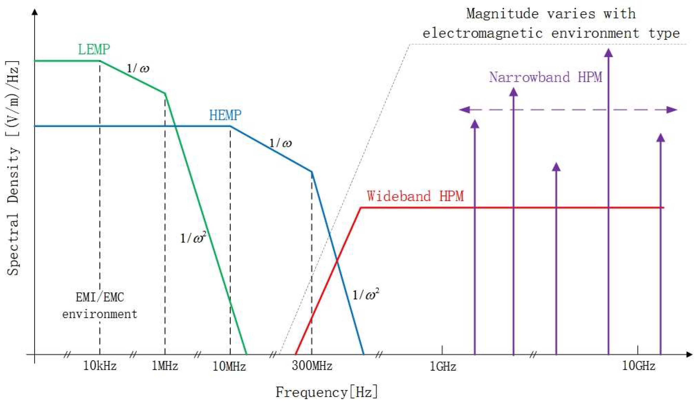
Strong EMI refers to the presence of high-amplitude electromagnetic disturbance signals that occur during the operation of electronic devices or systems. This high-amplitude EMI is evaluated relative to the normal operating environment of the electronic equipment or systems and has the potential to adversely affect their functionality and normal operation. This interference encompasses various types of waves, such as continuous waves (CWs), high-altitude electromagnetic pulses (HEMPs), lightning electromagnetic pulses (LEMPs), ultra-wideband electromagnetic pulses (UWB EMPs), and high-power microwaves (HPMs), among others [8]. To facilitate the classification of strong EMI, Giri and Tesche proposed a spectrum-based classification method, depicted in Figure 1 [9].
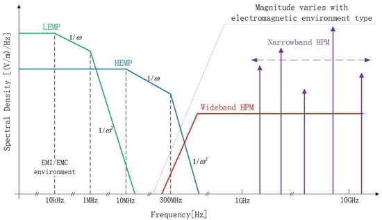
Figure 1.
Strong electromagnetic pulse waveform spectrum.
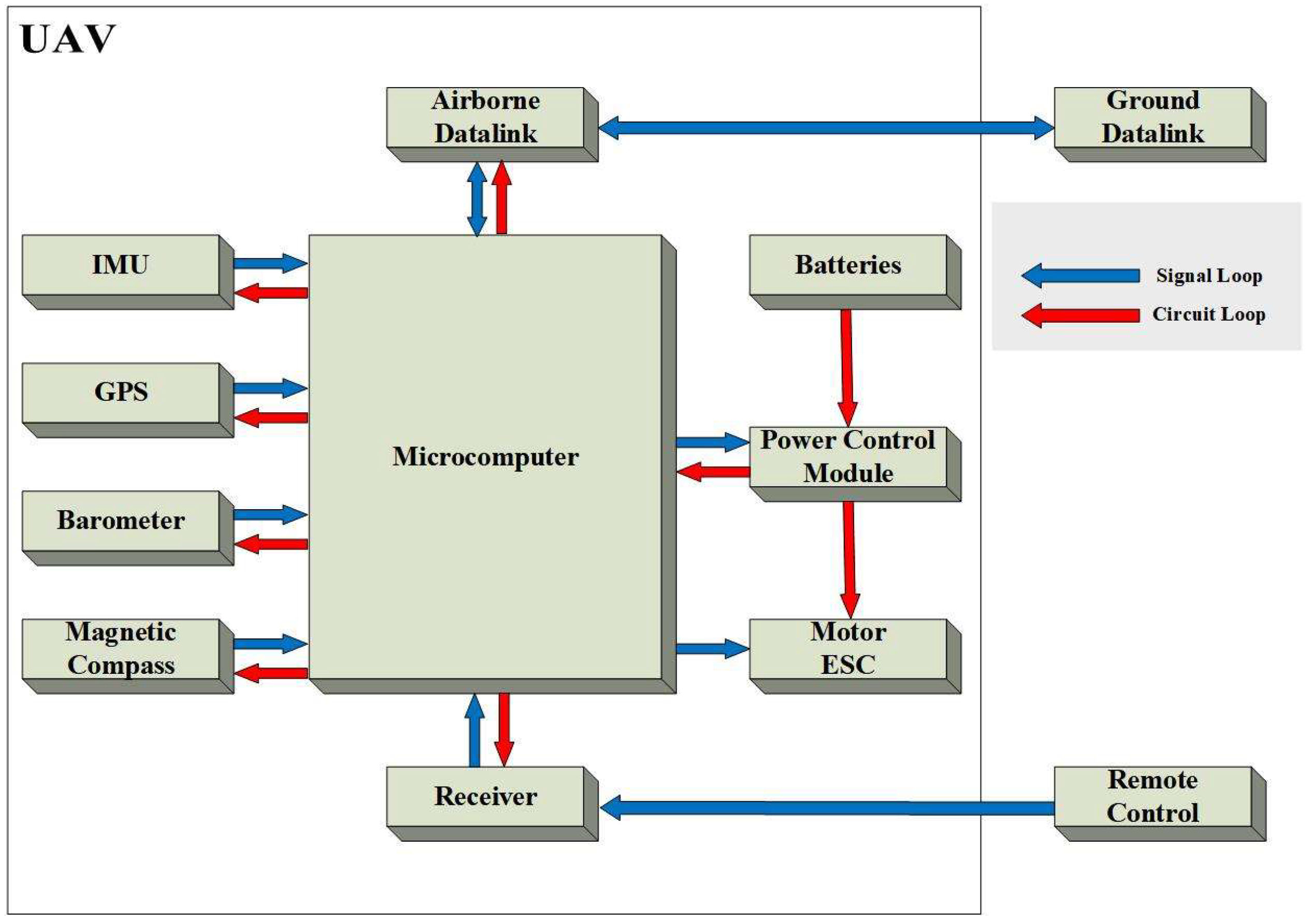
UAVs, as highly integrated electronic systems, consist of numerous electronic devices. From a holistic perspective, the UAV system can be divided into two loop systems, the signal loop and the circuit loop [10], as illustrated in Figure 2. The signal loop serves as the data transmission channel between UAV system components or between the UAV and the ground station, while the circuit loop represents the internal power supply circuitry of the UAV system. Strong EMI can couple into either of these loops, potentially impacting the internal electronics and subjecting the UAV to varying degrees of interference and damage.
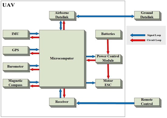
Figure 2.
UAV signal loop and circuit loop.
2.1. Effect of Strong Electromagnetism on the Datalink System
The UAV datalink system is a crucial two-way data transfer channel between the UAV and the ground control station, enabling real-time communication and long-distance remote control. It relies on wireless communication, including a data uplink for transmitting remote control signals and a data downlink for relaying the UAV’s status data and video images.
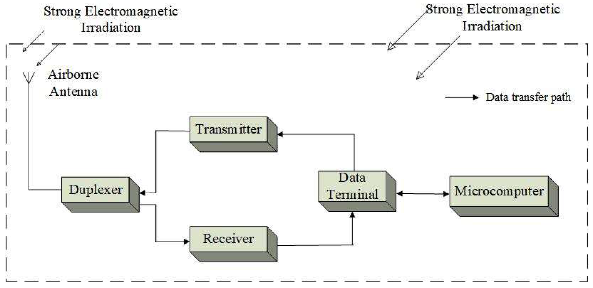
However, the antenna in the datalink system not only receives control signals from the ground station but also serves as a potential gateway for strong electromagnetic energy to enter the internal system. This can occur through front-door coupling and back-door coupling mechanisms, as depicted in Figure 3. The internal circuits of the UAV datalink system integrate numerous active sensitive devices, such as amplifiers and mixers [11]. Unfortunately, these devices are highly susceptible to interference from strong electromagnetic waves, leading to malfunction and impaired functionality.
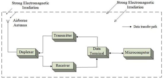
Figure 3.
Schematic of strong EMI on the datalink system.
The datalink system of UAVs is highly susceptible to strong EMI and has been a focal point of scholarly research. This paper presents Table 2, which offers a concise summary of the existing research on the impact of strong EMI on UAV datalink systems.

Table 2.
Current status of research on strong EMI on datalink systems.
CW interference, a common type of EMI, typically operates at low frequencies. Ref. [12] determined that the antenna is the primary coupling path for the datalink system by conducting CW irradiation tests and injection tests. It was observed that when the interfering signal frequency is close to the remote-control signal frequency, the RF front-end fails to effectively isolate the interfering signals, resulting in disruptions to the datalink. In Ref. [13], tests were conducted to assess the CW irradiation effects on UAV datalink systems. The results highlighted that the datalink cannot function properly under EMI at specific frequencies. Additionally, the polarization direction of the electromagnetic field can also influence the interference. MATLAB simulations were utilized in Ref. [14] to establish the relationship between the signal-to-noise ratio and the bit error rate (BER) of the datalink under single-frequency interference. Furthermore, a CW irradiation test on the datalink system was carried out, sweeping the frequency range from 200 MHz to 10 GHz in steps of 2 MHz, with a maximum electric field intensity of approximately 70 V/m. The findings indicate a higher probability of the datalink being unlocked when the interfering signal frequency falls within the operating frequency band of the telemetry link. This study elucidated the impact of CW interference at a single frequency on the datalink system. Building upon the irradiation test discussed in Ref. [14], Ref. [15] further confirmed the effect law and interference mechanism of single-frequency CW interference on the datalink system through CW injection tests. Ref. [16] extended the frequency sweep range and accuracy of the dynamic datalink test based on Ref. [14]. The irradiation source was swept from 0 to 18 GHz with a frequency step of 1 MHz, and the field intensity in the test area was increased to 200 V/m. Through these tests, sensitive frequency bands of the data uplink were identified, and the intrinsic connection between the field intensity threshold, automatic gain control (AGC) voltage, and BER was analyzed. Furthermore, Ref. [17] carried out in-band CW injection tests on the datalink system and investigated the effect of single-frequency and dual-frequency EMI on the datalink system. The results showed that, compared to single-frequency interference, when both frequencies of the dual-frequency interference fall within the operating band of the system, the energy causing the system to be unlocked is lower.
In addition to CW affecting the UAV datalink system, EMP can also have an impact and even cause permanent damage to the internal devices of the electronic system. Ref. [18] conducted irradiation tests on the UAV using three UWB EMP generators with different pulse repetition frequencies and amplitudes, and it was found that it can lead to the failure of the datalink between the remote control and the UAV. Analyzing the experimental results, it was determined that the amplitude magnitude has a greater effect on the UAV. Ref. [19] conducted electromagnetic irradiation tests using UWB EMP as the interference source and discovered that the data uplink of the UAV became unlocked when the repetition frequency was 5 Hz and the electric field intensity was 140 kV/m. Further test verification revealed that the first two low-noise amplifiers (LNA) inside the onboard receiver were damaged.
Unlike UWB EMP, where field intensity amplitudes dominate, the frequency of narrowband strong EMP has a greater impact on the UAV datalink system. In Ref. [20], L, S, and C-band HPM irradiation tests for UAV datalink were conducted, and the effect of different HPM bands on the UAV datalink system was summarized. On the one hand, when the HPM frequency falls within the datalink working band, the interfering signal can reach the RF front-end through the front-door coupling pathway, resulting in physical damage to the sensitive devices. On the other hand, when the frequency is far away from the working band, back-door coupling becomes the main coupling path, which can lead to an abnormal power supply to the datalink equipment. The study also demonstrated through theoretical calculations and interference signal injection tests that HPM can damage the LNA inside the receiver. In Ref. [21], a behavioral-level model of the UAV datalink system was constructed using SIMULINK to simulate the behavioral changes in the UAV after being subjected to HPM interference, and the simulation results aligned well with the results of the irradiation test.
Considering the potential variations in the effects of interference signals with different waveforms on the datalink, Ref. [22] established a typical electromagnetic pulse model. They employed simulation analysis methods to investigate the impacts of sinusoidal pulses, Gaussian noise, square-wave pulses, triangular pulses, electrically fast transient pulses, and surge pulses on the quality of image transmission in the data downlink. The results indicated that Gaussian noise, square wave pulses, and surge pulses exert a greater influence on the datalink. Additionally, sinusoidal pulses, Gaussian noise, and surge pulses have a more significant impact on the image transmission when the BER is similar among them.
Based on the aforementioned findings, it is apparent that extensive research has been conducted on the strong electromagnetic effects on the UAV datalink system. Various methods, including electromagnetic irradiation tests, electromagnetic injection tests, and simulation analysis, have been comprehensively employed to study the effects of different pulsed waves and continuous waves on the datalink system. However, most of the research has predominantly focused on analyzing the frequency of interfering signals, with comparatively less attention given to other parameters’ effects.
2.2. Effect of Strong Electromagnetism on the Flight Control and Navigation System
The flight control and navigation system is the central system of a UAV, consisting of the flight control module and navigation module, each serving specific functions. The system primarily comprises an inertial measurement unit (IMU), an onboard microcomputer, and a GPS receiver. The IMU integrates various sensor devices to measure the UAV’s three-axis attitude angle and motion parameters, as indicated in Table 3. The core component of the flight control and navigation system is the onboard microcomputer, responsible for processing and collecting signals from the sensors. It enables the intelligent control and autonomous decision-making of the UAV. The GPS receiver acquires satellite signals and continuously monitors the UAV’s real-time position information, providing accurate directional references and positional coordinates.

Table 3.
UAV’s main sensors and functions.
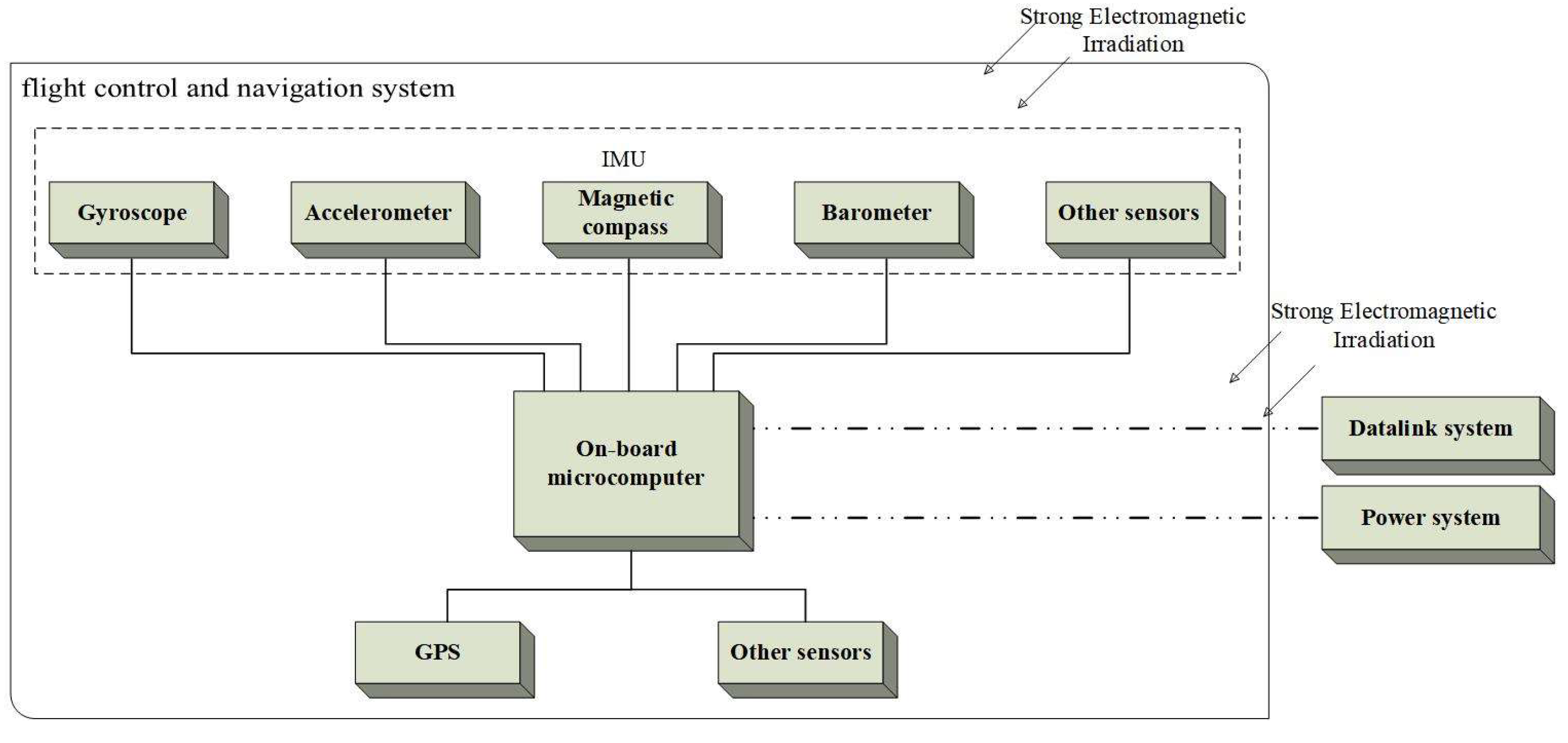
The flight control and navigation system of the UAV can be vulnerable to strong EMI, resulting in abnormal operation, as shown in Figure 4. Electromagnetic fields can interfere with sensors such as gyroscopes and magnetic compasses within the IMU, leading to compromised attitude estimation accuracy and reduced flight stability. Furthermore, EMI can impact the command signals from the onboard microcomputer, causing incorrect UAV operation. The GPS receiver, equipped with an antenna to receive satellite signals, faces challenges due to low power and long-distance transmission. To receive weak satellite signals, the receiver requires high sensitivity, thereby diminishing its ability to resist EMI. Table 4 presents a summary of the current state of research on the effects of strong EMI on the flight control and navigation system.
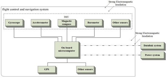
Figure 4.
Schematic of strong EMI on the flight control and navigation system. The dotted box at the top means that there are those five parts that make up the IMU, and the dotted line at the bottom means the connection to the on-board microcomputer to the other subsystems.

Table 4.
Current status of research on strong EMI on the flight control and navigation system.
The proper functioning of the flight control module is crucial for ensuring stable and safe UAV flight. However, operating in strong electromagnetic environments can lead to interference with various sensors and the onboard microcomputer, resulting in flight failures. Scholars have conducted investigations on the potential effects of strong EMI on UAV flight control modules. In Ref. [23], a test was conducted to examine the effects of LEMP magnetic fields on the magnetic sensor of the IMU, specifically under horizontal magnetic fields. It was observed that the magnetic sensor was significantly interfered with by the LEMP magnetic field, with the interference effect increasing as the magnetic field intensity rose. Ref. [24] focused on HEMP irradiation tests performed on a fixed-wing UAV under simulated flight conditions. When the electric field intensity reached 7.5 kV/m, it resulted in the disruption of normal circuit functions within the UAV and caused the onboard microcomputer to crash. Furthermore, a further increase in the field intensity led to the UAV’s descent and a loss of control. Examining the effects of HPM pulses ranging from 100 MHz to 3.4 GHz on various sensors of the flight control module, Ref. [25] conducted irradiation tests to assess their impact. By monitoring the UAV’s status and analyzing flight logs, significant changes in magnetometer readings were observed during the period of HPM pulse application, which then returned to normal after the pulses ceased. In Ref. [26], during HPM irradiation of the UAV, it was observed that the average rate of altitude decline was significantly higher than normal. The UAV’s flight direction also changed multiple times within a short period, exhibiting evident abnormal flight behavior, ultimately leading to an uncontrolled crash. An investigation indicated that the abnormal working of the flight control module, following the HPM attack, resulted in incorrect control instructions being issued, causing the UAV to lose control and crash.
To ensure stable navigation during UAV flight, most UAVs currently utilize a combination of inertial navigation and satellite navigation as their fundamental navigation method. Several scholars have conducted research on the impact of strong electromagnetic environments on satellite navigation receivers, revealing their susceptibility to EMI [36,37,38,39,40]. In Ref. [27], a mechanism analysis and experimental research were conducted on the interference of high-voltage line electromagnetic fields with UAV navigation systems. This study proposed a novel idea that plasma generated by high-voltage ionization produces a shielding effect on GPS signals. The shielding effect of corona plasma on electromagnetic waves was validated through tests and measurements. Quantitative tests on the positioning module were conducted in Ref. [28], where it was observed that the compass was affected when the power coupled to the cable reached −65.64 dBm. When the power reached −47.33 dBm, the GPS system was disabled. Under high electromagnetic field intensities of 470~862 MHz and 1.4~2.7 GHz, RF immunity tests were carried out in an anechoic chamber in Ref. [29]. The results indicated that the UAV’s GPS signal may be lost in strong electromagnetic environments of 1.4~2.7 GHz, which directly impacts the UAV’s autonomous control based on GPS positioning. The sensitivity of the BeiDou receiver to CW interference was investigated in Ref. [30]. Through simulations and irradiation and injection tests, it was concluded that antenna coupling is the main path for electromagnetic energy coupling. The interference effect of electromagnetic signals in the frequency band was found to be more evident. In Ref. [31], CW injection tests were conducted in the frequency range of 10 MHz to 5 GHz. The in-band electromagnetic sensitivity curves of different types of navigation satellite signals and the sensitive frequency bands of receiver unlocking were obtained. Additionally, a feasible method for EMI prediction applied to satellite navigation systems was proposed. The damage caused by LEMP to airborne GPS modules was studied in Ref. [32]. By using CST software and conducting injection tests on different ports of the GPS, changes in electromagnetic field intensity within the UAV under LEMP were obtained. Furthermore, damage thresholds of data input/output ports were identified. Wideband EMP irradiation tests on UAVs were conducted in Ref. [33] to analyze the effects of EMP irradiation at different repetition frequencies, field intensities, and power densities. Additionally, high-repetition-frequency UWB EMP irradiation tests were carried out in Ref. [34], using the DJI Mavic Pro UAV GPS receiver as the subject. The interference effects on the UAV GPS receiver resulted in phenomena such as failure to take off and loss of control. The coupling paths of irradiation interference on the navigation module were analyzed in Ref. [35] using an electromagnetic topology model. The model was simulated and tested in the frequency range of 2 MHz to 3 GHz, revealing that the coupling paths of electromagnetic waves vary across different frequency ranges.
In summary, scholars have investigated the effects of strong EMI on flight control and navigation systems. The studies indicate that strong EMI can disrupt the proper functioning of certain sensors and GPS receivers, thereby affecting the flight safety of UAVs. However, most current research primarily focuses on analyzing the phenomena observed on various sensors and GPS receivers, and further research on the operational processes, damage mechanisms, and coupling modes remains insufficiently in-depth.
2.3. Effect of Strong Electromagnetism on the Power System
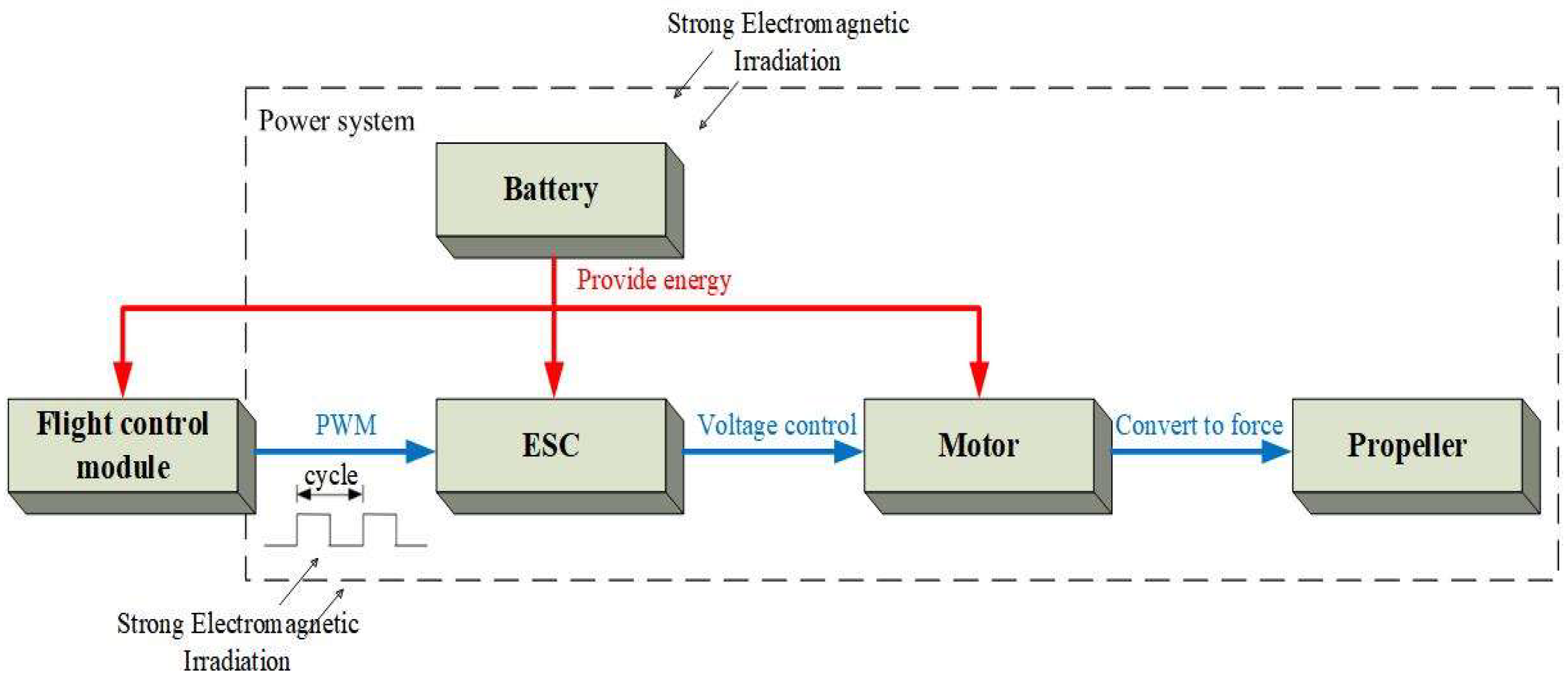
The power system serves as the source of flight power for UAVs, with the commonly used multi-rotor UAV as an example. The power system consists of four main components: the battery, motor, electronic speed control (ESC), and propeller [41]. Each component performs specific functions and roles, as outlined in Table 5. Notably, the motor and ESC play a crucial role in the flight stability and dynamic flight characteristics of the UAV. The ESC converts DC power to three-phase AC power and delivers it to the motor. The motor’s voltage is adjusted based on the pulse width modulation (PWM) signal output from the flight control module to control the motor speed [42].

Table 5.
Multi-rotor UAV power system components and functions.
When the UAV operates in a strong electromagnetic environment, certain components or circuits within the power system may be subjected to intense EMI, leading to malfunctions. Figure 5 illustrates a schematic diagram depicting the impact of strong EMI on the UAV power system. On the one hand, the interference can infiltrate the circuit through microstrip line coupling on the printed circuit board (PCB), causing damage to electronic components [43]. On the other hand, it can also affect the PWM control signal or cable voltage through cable coupling, resulting in motor runaway. Table 6 provides a summary of the current research on strong EMI on UAV power systems.
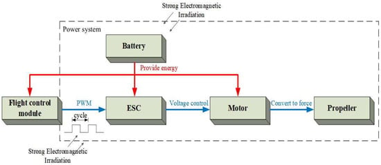
Figure 5.
Schematic of strong EMI on the power system.

Table 6.
Current status of research on strong EMI on the power system.
The power system is crucial for maintaining the flight of a UAV. When the power system experiences strong EMI, it can disrupt the UAV’s flight attitude and potentially lead to crashes or overturning. Consequently, research has been conducted to investigate the effects of strong EMI on the power system. In Ref. [44] the susceptibility of UAVs to high-powered electromagnetic pulses was analyzed based on control flow, resulting in a classification of three influence levels. Subsequent HPM irradiation tests revealed that the motors remained in a chattering state, suggesting that the MOSFET inside the ESC failed to function properly due to strong EMI. In Ref. [45], comparative tests were conducted on UAV motors operating in strong external magnetic fields using two different control algorithms. The results showed that the peak current of the motors increased significantly at a magnetic flux of 177 mT. While the motor speed controlled by the FOC algorithm remained relatively unchanged, the speed of motors controlled by the DTC algorithm varied by as much as 55%. The significant increase in current can shorten the flight time, and the change in motor speed can have a negative impact on flight, potentially leading to a UAV crash. Ref. [46] focused on the effects of L-band HPM on the working state of three typical UAVs. It was found that the motors and ESCs of two UAV types were damaged, resulting in their falling. A simulation indicated that HPM induced high-voltage pulses in the cable between the ESC and the motor, causing a sharp increase in motor speed and subsequent burnout. Through irradiation tests in Ref. [47], the coupling analysis of cable connections between the flight control module, ESC, and motor was explored. The study concluded that the cable serves as the primary coupling path for HPM energy, generating a high voltage and current that can damage UAV components. The coupling microwave frequency was also found to be related to the cable length. In Ref. [25], involving HPM irradiation on UAVs, the rotational speeds of the right front and left front motors decreased from 7500 rpm and 9000 rpm to 2000 rpm and 5000 rpm, respectively. It was found that HPM pulses can impact the PWM signals between the flight control module and the motor, leading to a sharp change in motor speed.
In summary, these studies have highlighted the impact of strong EMI on the motors, ESCs, and control signals of UAV power systems, thereby affecting flight performance. However, the majority of research has focused on HPM, with fewer studies exploring other forms of strong EMI. Additionally, the research mainly consists of summarizing and analyzing the observed phenomena, with limited studies delving into deeper coupling analysis and mechanisms.
3. Methods for the Study of Strong Electromagnetic Effects on the UAV
The study of strong EMI on electronic devices, equipment, and systems has been receiving increasing attention. Researchers have employed various methods to explore the damage mechanisms and laws associated with such interference. These methods can be broadly categorized into test research and simulation research. Test research involves simulating real working scenarios by setting different electromagnetic environments and test conditions. Researchers can obtain test data that help to evaluate the robustness and anti-interference capability of equipment and systems. Test research allows for practical validations of the performance of devices under different electromagnetic conditions. Simulation research, on the other hand, utilizes computer models and numerical simulation techniques to analyze the effects of strong EMI. By establishing mathematical and physical models, numerical calculations and simulations of electromagnetic field propagation, electromagnetic coupling, and electromagnetic effects can be performed. Simulation research aims to investigate the underlying mechanisms behind the effects of strong EMI on equipment and systems. This approach provides a more comprehensive analysis and enables the investigation of various parameters and mechanisms, even in cases where testing may be costly or challenging. The combined application of these research methods can provide strong support for understanding and responding to strong EMI.
3.1. Test Research
The interaction and coupling processes of strong EMI on target electronic devices, circuits, equipment, or systems involve multiple physical parameters. Theoretical analysis or modeling calculations may result in significant discrepancies between the obtained results and actual test results. Therefore, test research is typically necessary to accurately and realistically investigate the effects of strong EMI on these targets. To facilitate such experimental studies, corresponding test standards have been developed, such as the International Electrotechnical Commission-developed EMC test standard IEC-61000-4-3 [48], the U.S. military standards MIL-STD-461 [49] and MIL-STD-464 [50], the Radio Technical Commission for Aeronautics to develop the test standard DO-160 [51], and so on [52]. Test research on strong electromagnetic effects on equipment under test (EUT, referring to objects in different systems, including electronic devices, circuits, equipment, systems, etc.) can be classified into the following two main categories:
- Irradiation test: The EUT is directly exposed to the strong electromagnetic irradiation field. This method simulates electromagnetic fields in the real environment and can evaluate the performance and tolerance of devices in such scenarios.
- Injection test: High current or high voltage is directly injected or applied to the EUT, and it should be ensured that the waveform of the injected signal is consistent with the actual situation.
3.1.1. Irradiation Test
An irradiation test is commonly utilized for assessing the effects of strong EMI on electronic systems. This testing method involves irradiating the EUT while it is in operation by transmitting electromagnetic waves through an antenna. The working status of the EUT is monitored to determine the impact of the strong EMI. Additionally, this testing method enables the determination of the field intensity or power threshold required to induce specific phenomena.
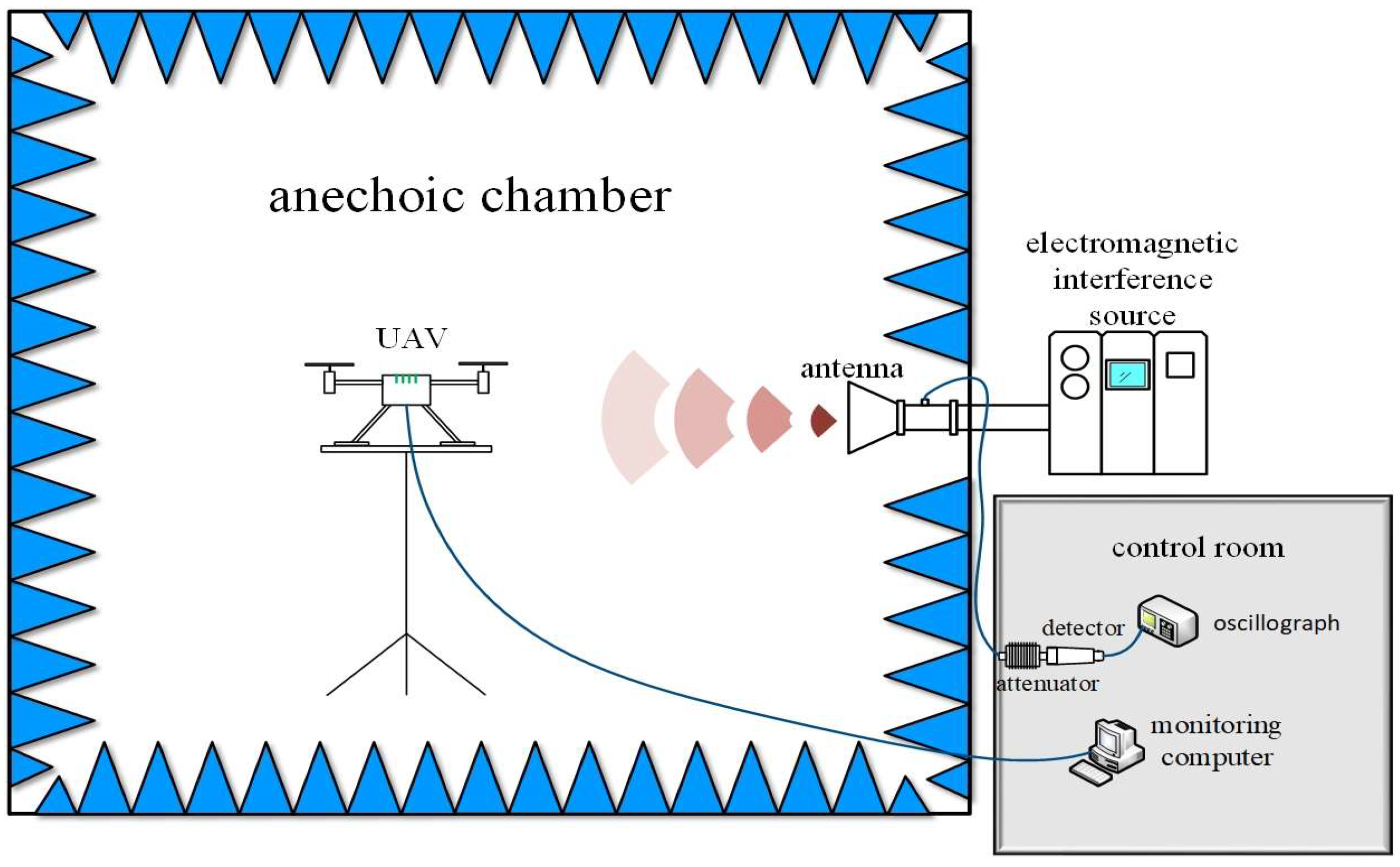
There are several common test sites used for irradiation testing, including outdoor test sites, a TEM chamber, reverberation chamber, and anechoic chamber. The characteristics of these test sites are summarized in Table 7. In the case of UAVs as the EUT, the most prevalent method is to conduct irradiation tests in an anechoic chamber. This method allows for more accurate measurements of the irradiation field intensity and energy density at the test location. Furthermore, it enables real-time monitoring of the UAV’s state and the occurrence of any relevant phenomena. Figure 6 illustrates the typical components of a test system used in such an irradiation test.

Table 7.
Irradiation test site and characteristics.
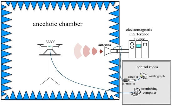
Figure 6.
Composition of the UAV anechoic chamber irradiation test system.
3.1.2. Injection Test
Although the irradiation test provides a more realistic representation of the electronic equipment’s performance in a strong electromagnetic environment, many laboratories lack the necessary test conditions and equipment for such testing methods. Consequently, scientists have proposed an injection test method, where large currents or high voltages are directly applied or injected into the EUT. Compared to the irradiation test, the injection test offers improved test efficiency for the same input power, and allows for the better control of interference signal parameters, resulting in more accurate data. There is some debate as to whether irradiation testing and injection testing can be fully equivalent, given the differences in the physical processes involved in the coupling and effects of electromagnetic irradiation versus signal injection on the EUT [53]. However, studies conducted in Refs. [54,55,56,57] have concluded that under specific conditions, the injection test can be considered as an equivalent replacement for irradiation testing. It can to some extent reflect the effect characteristics of the EUT under the interference of a strong electromagnetic environment.
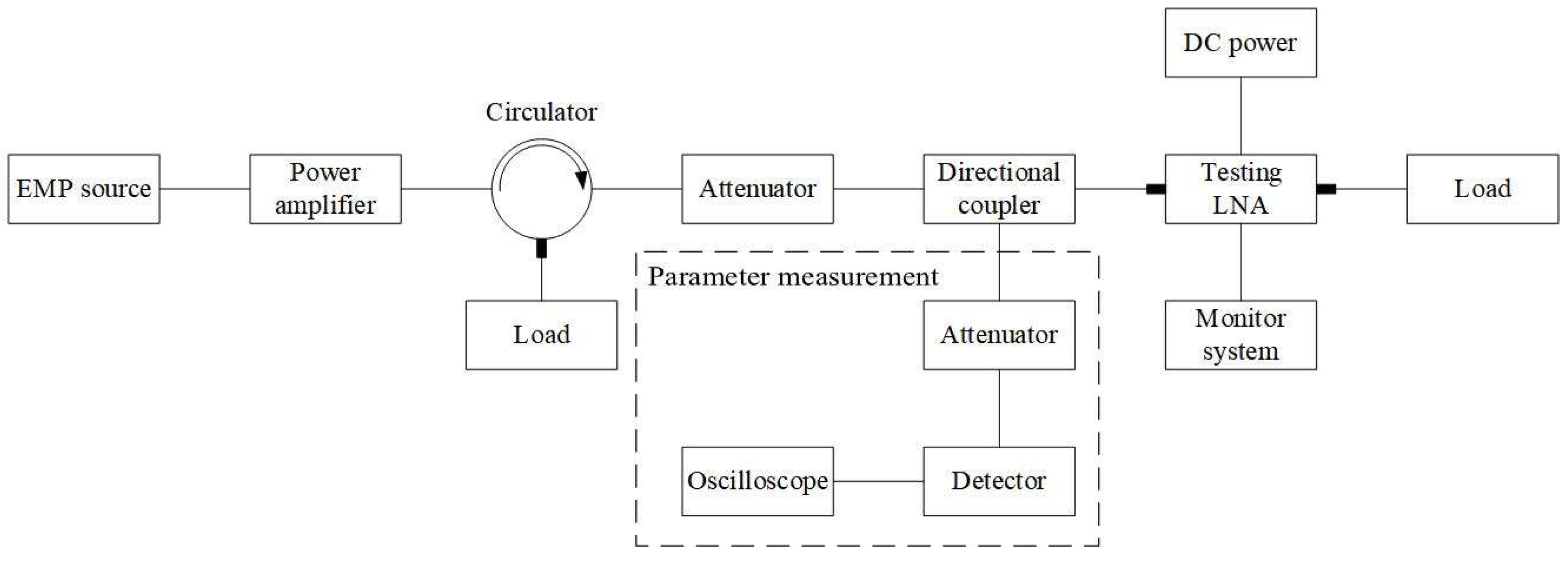
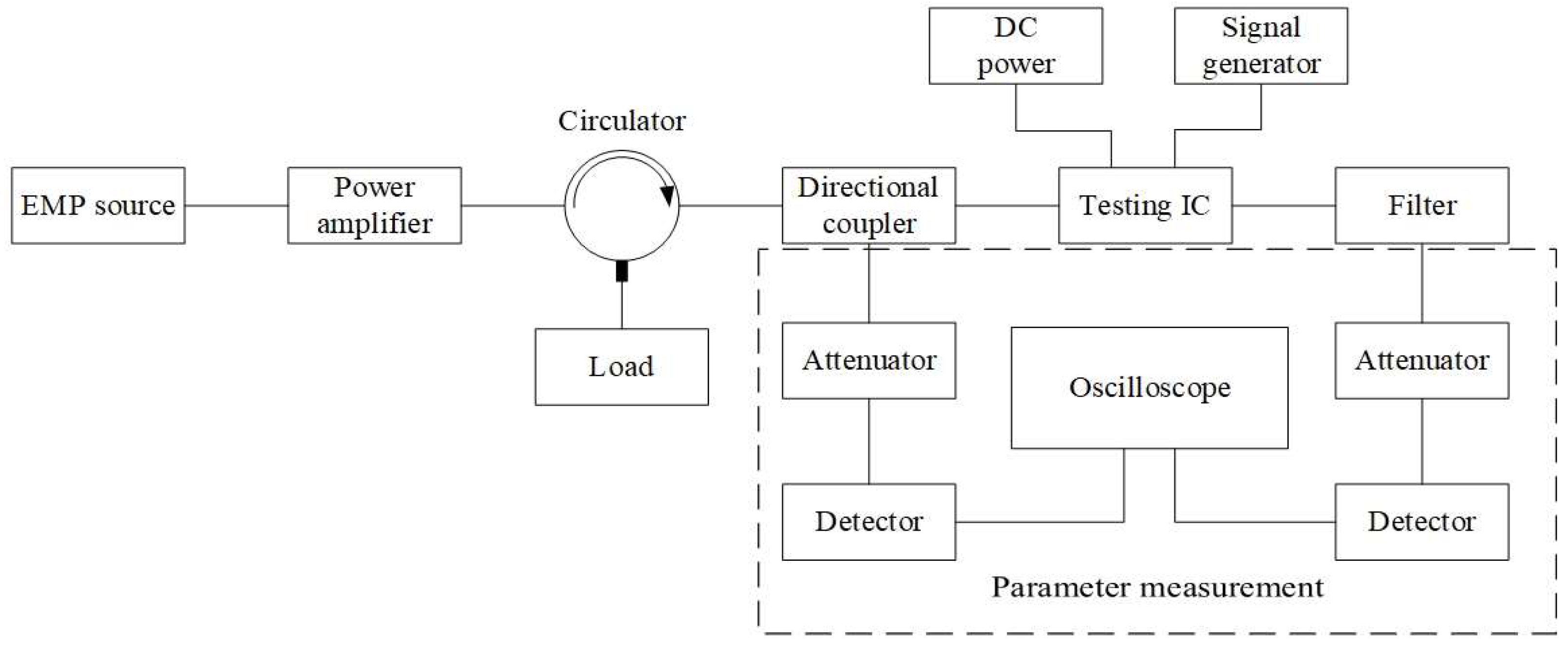
The injection test method is commonly applied in the evaluation of strong electromagnetic effects on electronic devices or circuits, such as LNAs and integrated circuits. The typical components of an injection test system can be seen in Figure 7 and Figure 8.
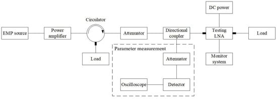
Figure 7.
LNA injection test system components.
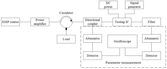
Figure 8.
IC injection test system components.
3.1.3. Summary
Irradiation tests and injection tests are the primary methods used to study strong electromagnetic effects. For UAVs, researchers can choose between these two methods, depending on the specific research objectives.
The irradiation test is the foundational method for investigating strong electromagnetic effects in UAVs and can be widely applied to study individual systems or devices. For example, in Ref. [58], an anechoic chamber test method was developed to assess the effects of EMP interference on the entire UAV. Additionally, irradiation tests can be targeted at specific subsystems or devices of the UAV. In Ref. [59], an irradiation test was conducted on the core components of the UAV datalink, while Ref. [60] focused on irradiation tests on the secondary remote control datalink system of the UAV. Moreover, Ref. [35] designed irradiation tests specifically for the UAV’s GPS positioning module.
However, due to the limitations of irradiation tests, accurately quantifying relevant test data can be challenging. In the case of circuits and devices like UAV datalinks and GPS navigation receivers, an injection test can provide a more precise determination of the observed phenomena and outcomes. For instance, Ref. [32] developed an equivalent alternative test method for the electromagnetic effects of UAV GPS modules based on LEMP injections. Similarly, Ref. [15] designed a research method on the electromagnetic effects of UAV datalinks using the injection method.
When selecting the appropriate test method, it is essential to strike a balance between test conditions, the simulation accuracy of the test environment, and the EUT. This enables control over the cost and technological considerations associated with the testing process.
3.2. Simulation Research
With the rapid advancement of computer arithmetic, simulation technology has become widely employed in scientific research. Electromagnetic simulation involves the modeling and simulation of the electromagnetic performance of the research object. Instead of using physical prototypes, researchers utilize established models to analyze and calculate various parameters. This enables the study of field changes, heat distribution, force distribution, and structural characteristics within electronic systems, devices, and circuits under different electromagnetic environments. Researchers can uncover the damage mechanisms and underlying laws governing their behavior.
Benefiting from the development of supercomputers, high-performance electromagnetic computational methods and technologies have advanced rapidly. Typical electromagnetic simulation methods can be divided into time domain and frequency domain algorithms, from which numerous different types of electromagnetic simulation software are derived, as shown in Table 8.

Table 8.
Electromagnetic simulation methods and typical software.
Electromagnetic simulation methods are widely used in the study of strong electromagnetic effects in electronic systems. Ref. [61] proposed a numerical simulation method based on finite elements in the frequency and time domain for simulating the coupling of the electromagnetic wave to the wire in a metallic cavity with small apertures and slits. Ref. [62] utilized CST to establish a simulation model of the UAV shell and tested its shielding effectiveness. Furthermore, Ref. [63] employed CST to simulate the transient voltage and current changes caused by internal cables in aircraft under electromagnetic pulse irradiation, and proposed a cable layout scheme to mitigate the risk of lightning strikes.
Apart from electromagnetic simulation methods, various other numerical simulation methods have also been applied in the study of strong electromagnetic effects in electronic systems. Ref. [64] investigated the electromagnetic semi-physical simulation technique for UAVs and proposed the electromagnetic simulation method injected from the antenna port and on-board cables. Ref. [65] investigated the effect of UWB EMP on UAV wireless communication based on MATLAB/SIMULINK. Ref. [66] designed a multi-UAV path planning scheme for finding the lowest cost flight path in a radar-interfering environment. Ref. [67] proposed a method for assessing the degree of interference of UAV datalink in complex environments by combining support vector machines and power criterion. Ref. [68] proposed a method based on a convolutional neural network for the EMI identification and electromagnetic environment risk assessment of a UAV datalink.
Simulation has proven to be a valuable and successful tool in studying strong electromagnetic effects. By establishing reasonable simulation models, applying appropriate calculation methods, and adjusting solving parameters accordingly, simulation can to some extent replace physical tests. The high efficiency and flexibility of simulation greatly enhance research productivity. Therefore, a research approach combining simulation and physical testing is vital for advancing our understanding of strong electromagnetic effects in electronic systems.
4. Protection against Strong EMI for the UAV
With the increasing complexity of the electromagnetic environment, the design of strong electromagnetic protection for UAVs has become a significant area of research. EMC theory, which encompasses EMI sources, coupling paths, and sensitive equipment, applies to electromagnetic protection research as well. However, due to the uncertainty and variability of EMI sources, it is challenging to achieve effective protection by limiting them. As a result, the focus is primarily on two aspects: the coupling path and the sensitive equipment. Traditional strong electromagnetic protection methods for UAVs include front-door protection and back-door protection [69]. In addition, some new technologies have been gradually applied to the field of strong electromagnetic protection on the UAV.
4.1. Front-Door Protection Methods
Front-door coupling refers to the entry of electromagnetic wave energy into the internal electronic system through signal channels such as antennas or sensors. This energy generates current that flows through the wiring, primarily along the cables, potentially leading to damage to the front-end equipment within the system [70]. Front-door protection involves implementing measures to reduce the coupling of electromagnetic energy from antennas and sensors or to limit its transmission into the system. Methods include protection technologies based on surface electromagnetic structures and limiting technologies, and so on.
4.1.1. Protection Technologies Based on Surface Electromagnetic Structures
Two typical methods within this category involve using frequency selective surface (FSS) or energy selective surface (ESS) as shields for the antennas. FSS is a two-dimensional periodic array structure composed of resonant units, typically metal patch units or aperture units on a metal plate or other active devices. FSS can achieve both the in-band passage and out-of-band absorption of electromagnetic waves [71], thereby reducing the coupling energy of antennas to out-of-band EMI. Ref. [72] proposed a communication band shielding configuration method based on UAV-Drive FSS, which can shield the communication band from EMI, and can also be used for the shielding design of the datalink system of the UAV itself. The ESS is an electromagnetic structure with the ability to transform wave impedance nonlinearly, transmitting low energy and shielding high energy electromagnetic signals [73]. If the ESS is applied to UAV protection, the energy amplitude subjected to EMI can be reduced, thus protecting internal devices and circuits. Ref. [74] proposed a strong, adaptive electromagnetic protection method based on ESS to enable an adaptive protection threshold and self-triggering characteristic.
4.1.2. Limiting Technologies
In addition to reducing the electromagnetic energy coupled to the UAV at the front-end of the antennas and sensors, limiting technologies are also commonly used for front-door protection. Adding RF front-end protection units to reduce the transmission of electromagnetic energy to the internal UAV system, such as through the use of limiting devices in the front-end of the receiver, can weaken the interference signal and protect the internal system. For instance, limiting devices such as gas discharge tubes (GDT), metal oxide varistors (MOV), and transient voltage suppression (TVS) are often used [75,76,77]. Ref. [78] evaluated the anti-HEMP protection performance of the front-end equipment of the receiving antenna system based on electromagnetic coupling simulation and an injection test, and examined the conduction-coupling response characteristics of the surge protector, and verified the protection function of the surge protector for a low-voltage antenna system. Ref. [79] discussed the electromagnetic protection effect of a differential limiter in the receiver, and its use in the front stage of LNA can effectively suppress the strong EMI without affecting the reception and amplification of weak communication signals. Ref. [80] conducted a wideband HPM irradiation test on a UAV datalink to examine the protection effect by adding limiting protection modules in the RF front-end. In Ref. [81], a comprehensive field-circuit protection method is proposed by considering the front-door protection methods of the RF front-end, which can effectively protect the sensitive modules and devices from the influence of strong EMI.
4.2. Back-Door Protection Methods
Back-door coupling refers to electromagnetic energy entering the internal electronic system through aperture, ground, power line, or direct penetration, forming a complex electromagnetic field distribution which affects the sensitive circuits or components and prevents the system from working normally [82]. Back-door protection is mainly implemented by taking measures to reduce the electromagnetic field energy coupled into the system, and there are different protection methods for different coupling paths.
4.2.1. Shielding Protection
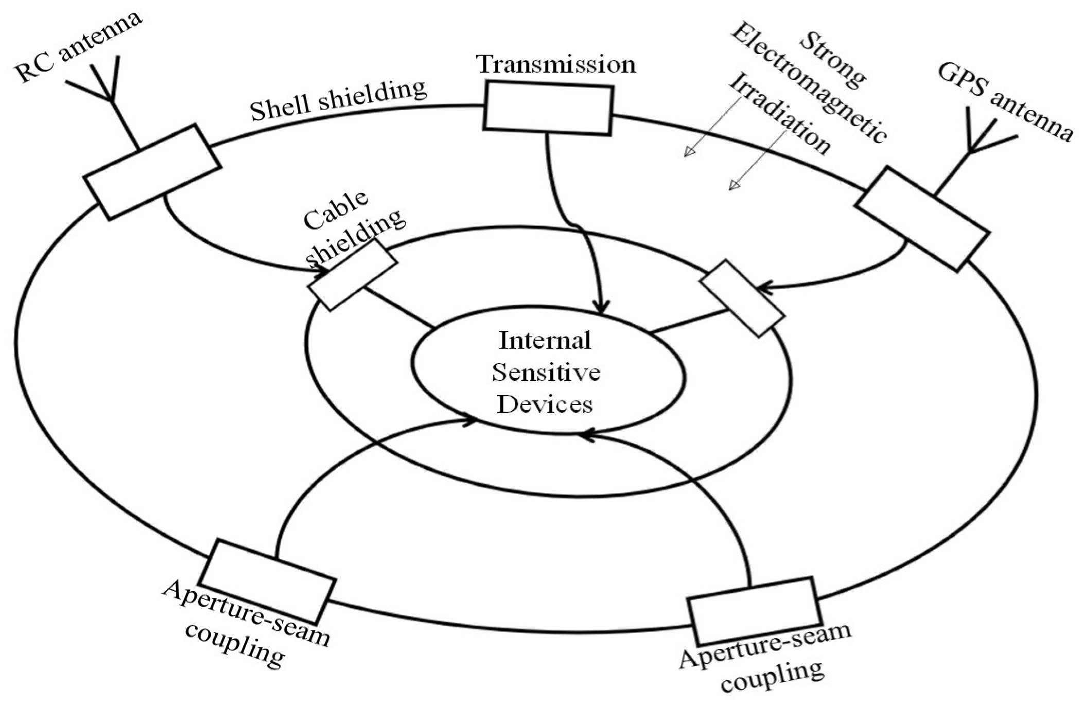
Electromagnetic shielding aims to restrict the propagation of EMI through space. It involves using a shield to surround and protect a device or circuit, causing the EMI signal to be attenuated through reflection or absorption. In the context of strong electromagnetic protection for UAVs, shielding methods primarily include shell shielding and cable shielding. The electromagnetic shielding topology model for UAVs is illustrated in Figure 9.
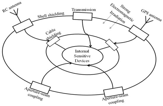
Figure 9.
Electromagnetic shielding topology model for the UAV.
Shell shielding involves using materials with electromagnetic shielding or absorbing properties for the UAV’s outer shell to minimize the transmission of EMI to the internal system. Commonly used materials in UAV shell manufacturing include carbon fiber composites, glass fiber composites, and plastics, chosen for their lightweight characteristics [83]. While these materials may have excellent mechanical properties, they often lack sufficient electrical conductivity to effectively shield against electromagnetic waves. To enhance the shielding properties of the enclosure, a highly conductive layer can be embedded within the composite material [84] or specific wave-absorbing structures can be utilized to shield electromagnetic waves [85]. Additionally, the placement of heat dissipation apertures on the UAV shell should be strategically distributed to minimize the coupling energy of strong EMI.
In a study conducted by Ref. [86], the installation of aluminum foil on the shell of the UAV was utilized as a shielding measure to investigate its effectiveness against LEMP. The results demonstrated that the maximum voltage recorded within the UAV cabin was only 1 V when subjected to a 150 kV lightning pulse. This finding indicates that the application of aluminum foil on the UAV’s surface successfully reduced the impact of EMI. In Ref. [87], low-level swept field tests were employed to analyze the variations in shielding effectiveness among different materials, including carbon fiber composites and aluminum, as well as the impact of the test samples’ apertures. In Ref. [88], a proposition was made to apply a layer of reduced graphene oxide on the shell of the UAV in order to assess its effectiveness in electromagnetic shielding within the frequency range of 100 MHz to 10 GHz. The results demonstrated that the material exhibited a low reflection coefficient and a high absorption capacity, indicating its suitability as an ideal material for electromagnetic shielding purposes. In Ref. [89], COMSOL multiphysics simulations were utilized to model the impact of LEMP on the nose, wings, and fuselage of the UAV. The findings indicated that by adequately covering the surface of the UAV’s shell with a layer of effective electrical conductors, it was possible to fundamentally prevent lightning from entering the UAV. Ref. [90] investigated the electromagnetic shielding effect of UAV shells with different aperture positions under plane wave irradiation with different polarization directions using the modal method of moments. It was shown that both the aperture positions and the irradiation field polarization directions have significant influence on the electromagnetic shielding effect of the shells.
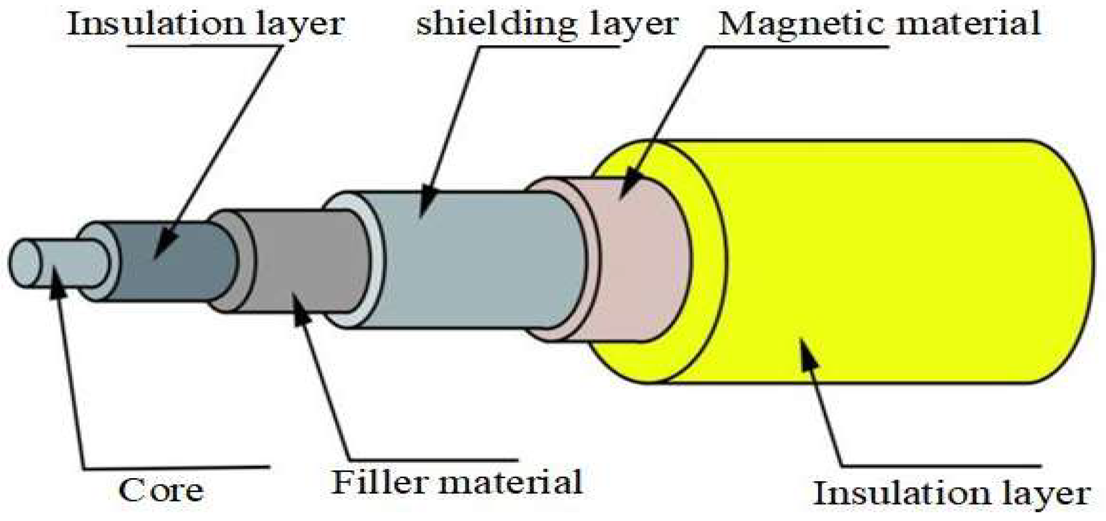
Cables, as the conduits for information and power transmission between electronic systems, are often directly exposed to complex electromagnetic environments, making them susceptible to interference [91]. Cable shielding is employed to reduce the electromagnetic energy coupled to the cables by incorporating a shielding layer, thereby enhancing their resistance to external EMI. The structure of a shielded cable is shown in Figure 10.
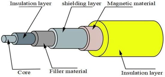
Figure 10.
Shielded cable construction.
Ref. [92] investigated the shielding efficiency of UAV airborne cables and experimentally verified that the shielding efficiency depends on the type of EMI. Ref. [93] analyzed the performance of an aircraft cable protection system consisting of shielding and drain wire in indirect lightning strike environments through testing and computational simulation. Ref. [94] established and compared crosstalk prediction models for two different shielded cables based on transmission line theory, and also investigated the effect of the structural parameters of the cable shield on the shielding performance. In addition to the cable shielding performance affecting the electromagnetic protection result, the cable layout inside the UAV also has an influence. Ref. [95] proposed reducing the impact of EMI on UAV systems by designing cable laying channels, grounding methods, and earthing points in an appropriate way. Ref. [96] simulated the internal cable coupling of the UAV under strong EMP and investigated the effect of the wiring method and cable type on the induced voltage.
4.2.2. Conduction Protection
In a strong electromagnetic environment, conductors such as cables inside the UAV may couple electromagnetic energy and transmit it as voltage and current through the cables to the internal system [97]. Conduction protection involves the installation of nonlinear circuit elements between the cables within the UAV to mitigate the impact of interference on the system through voltage clamping or current release. The main measures employed for conduction protection include limiting and filtering. Unlike the front-door protection’s use of limiting technologies, conduction protection applies these measures to the circuits inside the UAV rather than the RF front-end. Filtering restricts specific frequency components of the signal from passing through the protected circuit system.
In typical conduction protection circuits, the combination of limiting and filtering methods is often used to create multi-level protection networks, offering enhanced protection against strong EMI. In Ref. [98], in order to reduce the impact of transient and surge voltage on the power source and electronic equipment of UAV, researchers proposed the design idea of an airborne power surge protector, and verified its surge suppression performance. Ref. [99] conducted a test of the HEMP conduction protection module using a pulsed current injection test system. Ref. [100] designed a conduction protection component for wireless communication systems against strong EMP using transient current release and steady state filtering, which can be applied in the UAV datalink module.
4.3. New Technologies of Strong Electromagnetic Protection for the UAV
Due to the increasingly complex and challenging electromagnetic environment, as well as the trend of electronic systems towards miniaturization, integration, and intelligence, traditional methods of strong electromagnetic protection face limitations in addressing current bottleneck issues. Consequently, new materials and technologies such as new electromagnetic protection materials [101], electromagnetic bionic technology [102], and electromagnetic adaptive protection technology [103] have gained significant attention and are gradually being applied in the design of strong electromagnetic protection for electronic systems.
In Ref. [104], a software solution was developed to address the problem of power interference causing the resetting of the flight control and navigation system of UAVs. This software enables the automatic reset and resumption of normal operation for the digital signal processor, even after interference has occurred. Ref. [105] investigated a narrowband interference suppression technique based on fast Fourier transform, providing a solution that can adapt to changing interference environments and effectively suppress narrowband interference in UAV networks. Ref. [106] proposed an anti-jamming method for UAV swarm communication based on spectrum sensing, intelligent decision-making, adaptive interference and signal separation, dynamic spectrum access, and other cognitive communication technologies. This method enables UAV swarms to communicate under EMI. In Ref. [107], the modeling and testing of UAV electronic systems demonstrated that pulse-coupled waveforms under high-field-intensity conditions could be accurately predicted using low-amplitude field intensity data as a training set. This method provides a simple and effective simulation technique for predicting the response of electronic devices to electromagnetic pulses. Ref. [108] proposed an intelligent anti-jamming design method specific to UAVs, focusing on the airborne end. This method enables the automatic identification of EMI frequency, intensity, and type, as well as an assessment of the threat level. It then automatically takes appropriate measures, such as adjusting the antenna direction, increasing the working signal power, and changing the movement direction, to circumvent EMI. Ref. [109] proposed an electromagnetic protection method against in-band interference based on injection test results of the datalink. By monitoring the electromagnetic environment in real-time and establishing a database from previous test results, when it is determined that external EMI is sufficient to affect normal UAV operation, the UAV automatically switches the working frequency to eliminate the impact of in-band EMI. Ref. [110] introduced a cognitive module to enhance the anti-EMI capability of frequency hopping technology. The proposed highly robust frequency hopping technology based on cognition enables adaptive frequency hopping to counteract EMI.
The methods of strong electromagnetic protection vary depending on the type of UAV. For instance, rotary-wing UAVs and fixed-wing UAVs exhibit significant differences in their structures and operating principles, consequently leading to distinct electromagnetic protection requirements and methods. Rotary-wing UAVs, characterized by multiple rotating motors and smaller sizes with high device integration, necessitate electromagnetic protection measures that account for both external electromagnetic interference and internal component interactions. In contrast, fixed-wing UAVs have fewer rotating parts, resulting in electromagnetic protection primarily focusing on the communication and navigation links’ anti-interference performance. Common protection methods include shielding electronic equipment, optimizing cable layout, and reinforcing shell shielding. Moreover, the methods of electromagnetic protection can also vary based on the classification of different flight scenarios. UAVs used for aerial photography, logistics, and similar tasks encounter minimal external EMI during flight and therefore prioritize internal EMI. Conversely, UAVs employed for electric power surveys or flights at high altitudes are more susceptible to strong EMI and require comprehensive protection utilizing various methods.
5. Conclusions
The vulnerability of UAVs to strong EMI has become increasingly prominent with the expansion of the UAV market and system integration. This paper provides a review of research on strong EMI in UAVs and introduces commonly used research methods for studying strong EMI. Additionally, it discusses protection methods to address strong EMI.
The research into strong EMI on UAV mainly focuses on the typical front-door coupling paths, such as the datalink system and the navigation receiver, with fewer studies targeting back-door coupling. Most of the research adopts a combination of test and simulation, but the monitoring methods of the test research are relatively isolated, and the modelling accuracy of the simulation research still fails to reach the level of the principled research. Various means of strong EMI protection exist, but purely traditional methods often struggle to meet protection requirements. The application of new protective materials and technologies is still in the research stage and has not been practically applied in the UAV design process.
In light of the aforementioned research gaps, we aim to address these deficiencies and advance the field in the following areas. Firstly, we will enhance our experimental methods by incorporating additional monitoring techniques. This will allow us to integrate the macroscopic phenomena resulting from strong EMI with a deeper understanding of the underlying mechanisms. Secondly, we will consider the structural and material parameters of UAVs and establish more accurate simulation models and algorithms to obtain precise simulation results. This is particularly challenging due to the complex nature of UAVs as relatively large electronic systems. Finally, we will explore and introduce novel electromagnetic protection technologies into the design and manufacturing of UAVs, thereby enhancing their resilience against strong electromagnetic interference.
In summary, although there have been research efforts on strong EMI and protection in UAVs, this field is still in its early stages. As new technologies and materials are continually applied to UAVs, related research must keep pace with these advancements. There is still ample room for improvement in the research on strong EMI and protection in UAVs, including but not limited to the following aspects:
- Quantifying test research: The credibility of simulation-based research data is limited, so it is important to improve testing methods to gather measured data and ensure reliability.
- Diversifying monitoring methods: Most existing studies focus on observing obvious phenomena, but strong EMI on electronic systems often manifests as microscopic phenomena. Therefore, there is a need to explore more accurate monitoring methods.
- Systematizing mechanism analysis: While current studies mainly focus on internal component damage, understanding how component damage leads to overall UAV system failure is equally important.
- Developing practical protection methods: Traditional shielding and limiting methods often struggle to meet strong EMI protection requirements. Therefore, it is necessary to consider factors such as cost and effectiveness, and to incorporate more practical and reliable methods into UAV design and production.
Author Contributions
Conceptualization, Z.Z. and Y.Z. (Yang Zhou); investigation, Z.Z.; resources, Y.Z. (Yang Zhou) and Y.Z. (Yang Zhang); writing—original draft preparation, Z.Z.; writing—review and editing, Y.Z. (Yang Zhou) and Y.Z. (Yang Zhang); supervision, B.Q.; project administration, B.Q. All authors have read and agreed to the published version of the manuscript.
Funding
This research was funded by the Hunan Natural Science Foundation (2023JJ40675) and School Research Programma of National University of Defense Technology (Approval No. ZK22-42).
Data Availability Statement
The data presented in this study are available in this article.
Conflicts of Interest
The authors declare no conflicts of interest.
Abbreviations
The following abbreviations are used in this manuscript:
| UAV | unmanned aerial vehicle |
| EISAT | electronic information science and technology |
| MCU | microcontroller unit |
| AI | artificial intelligence |
| EMI | electromagnetic interference |
| EMC | electromagnetic compatibility |
| CW | continuous wave |
| HEMP | high-altitude electromagnetic pulse |
| LEMP | lightning electromagnetic pulse |
| UWB EMP | ultra-wideband electromagnetic pulse |
| HPM | high-power microwave |
| BER | bit error rate |
| AGC | automatic gain control |
| LNA | low-noise amplifier |
| IMU | inertial measurement unit |
| ESC | electronic speed control |
| PWM | pulse width modulation |
| PCB | printed circuit board |
| EUT | equipment under test |
| FDTD | finite difference time domain |
| FIT | finite integration technique |
| FEM | finite element method |
| MOM | method of moments |
| FSS | frequency selective surface |
| ESS | energy selective surface |
| GDT | gas discharge tube |
| MOV | metal oxide varistor |
| TVS | transient voltage suppression |
References
- Li, B.; Fei, Z.; Zhang, Y. UAV Communications for 5G and Beyond: Recent Advances and Future Trends. IEEE Internet Things J. 2019, 6, 2241–2263. [Google Scholar] [CrossRef]
- Luo, Y.; Yu, X.; Yang, D.; Zhou, B. A survey of intelligent transmission line inspection based on unmanned aerial vehicle. Artif. Intell. Rev. 2022, 56, 173–201. [Google Scholar] [CrossRef]
- Selvaraj, R.; Kuthadi, V.M.; Baskar, S. Real-time agricultural field monitoring and smart irrigation architecture using the internet of things and quadrotor unmanned aerial vehicles. Agron. J. 2022, 115, 1–20. [Google Scholar] [CrossRef]
- Lyu, M.; Zhao, Y.; Huang, C.; Huang, H. Unmanned Aerial Vehicles for Search and Rescue: A Survey. Remote Sens. 2023, 15, 3266. [Google Scholar] [CrossRef]
- Motlagh, N.H.; Kortoçi, P.; Su, X.; Lovén, L.; Hoel, H.K.; Haugsvær, S.B.; Srivastava, V.; Gulbrandsen, C.F.; Nurmi, P.; Tarkoma, S. Unmanned Aerial Vehicles for Air Pollution Monitoring: A survey. IEEE Internet Things J. 2023, 10, 21687–21704. [Google Scholar]
- Peddinti, P.R.T.; Puppala, H.; Kim, B. Pavement Monitoring Using Unmanned Aerial Vehicles: An Overview. J. Transp. Eng. B Pavements 2023, 149, 03123002. [Google Scholar] [CrossRef]
- Li, Y.; Ding, Q.; Li, K.; Valtchev, S.; Li, S.; Yin, L. A Survey of Electromagnetic Influence on UAVs from an EHV Power Converter Stations and Possible Countermeasures. Electronics 2021, 10, 701. [Google Scholar] [CrossRef]
- Fei, C.; Wei, X.D. Summary of Research on Strong Electromagnetic Pulse Effect in Radar Receiver. Sci. J. Intell. Syst. Res. 2021, 3, 155–161. [Google Scholar]
- Giri, D.V.; Tesche, F.M. Classification of Intentional Electromagnetic Environments (IEME). IEEE Trans. Electromagn. Compat. 2004, 46, 322–328. [Google Scholar]
- Sun, Y.; Li, L.; Wang, W. Discussion on the Safety Engineering of UAV in UHV Transmission Line Routing Inspection. Shandong Electr. Power 2017, 44, 15–19. [Google Scholar]
- Zhu, X.; Lai, J.; Chen, S. Cooperative Location Method for Leader-Follower UAV Formation Based on Follower UAV’s Moving Vector. Sensors 2022, 22, 7125. [Google Scholar]
- Chen, Y.; Zhang, D.; Cheng, E.; Wang, X. Investigation on susceptibility of UAV to radiated IEMI. In Proceedings of the 2018 IEEE International Symposium on Electromagnetic Compatibility and 2018 IEEE Asia-Pacific Symposium on Electromagnetic Compatibility (EMC/APEMC), Suntec City, Singapore, 14–18 May 2018. [Google Scholar]
- Zhang, T.; Chen, Y.; Cheng, E. Continuous wave radiation effects on UAV data link system. In Proceedings of the 2013 Cross Strait Quad-Regional Radio Science and Wireless Technology Conference, Chengdu, China, 21–25 July 2013. [Google Scholar]
- Du, B.; Chen, Y.; Cheng, E.; Zhang, D.; Tian, Q. Experiment Analysis of Continuous Wave Electromagnetic Irradiation Effect for a Certain Type of UAV Data Link. J. Microw. 2018, 34, 86–91, 96. [Google Scholar]
- Du, B.; Chen, Y.; Gao, W.; Liu, L.; Cheng, E.; Zhang, D. Research on Electromagnetic Effect of Unmanned Aerial Vehicle Data Link Based on Injection Method. High Volt. Eng. 2018, 44, 3322–3327. [Google Scholar]
- Zhang, D.; Chen, Y.; Cheng, E.; Zhang, Q. Electromagnetic radiation effects on dynamic datalink of UAV. J. Terahertz Sci. Electron. Inf. Technol. 2020, 18, 643–649. [Google Scholar]
- Xu, T.; Chen, Y.; Wang, Y.; Zhao, M. Research on In-Band Continuous Wave Electromagnetic Interference Effect of Unmanned Aerial Vehicle Data Link. J. Beijing Inst. Technol. 2021, 10, 1084–1094. [Google Scholar]
- Yu Sakharov, K.; Sukhov, A.V.; Ugolev, V.L.; Gurevich, Y.M. Study of UWB Electromagnetic Pulse Impact on Commercial Unmanned Aerial Vehicle. In Proceedings of the 2018 International Symposium on Electromagnetic Compatibility (EMC EUROPE), Amsterdam, The Netherlands, 27–30 August 2018. [Google Scholar]
- Gao, S.; Cheng, E.; Chen, Y.; Wang, Y. Research on ultra-wideband electromagnetic pulse irradiation effect and protection method of Unmanned Aerial Vehicle. J. Phys. Conf. Ser. 2019, 1325, 012165. [Google Scholar]
- Zhang, D.; Zhou, X.; Cheng, E.; Wan, H.; Chen, Y. Investigation on Effects of HPM Pulse on UAV’s Datalink. IEEE Trans. Electromagn. Compat. 2020, 62, 829–839. [Google Scholar] [CrossRef]
- Gao, C.; Xue, Z.; Li, W.; Ren, W. The influence of electromagnetic interference of HPM on UAV. In Proceedings of the 2021 International Conference on Microwave and Millimeter Wave Technology (ICMMT), Nanjing, China, 23–26 May 2021. [Google Scholar]
- Jia, Y.; Tu, X.; Yan, W.; Wang, E.; Zhao, Y.; Ding, S. Study on the Influence of Electromagnetic Pulse on UAV Communication Link. Am. J. Electr. Electron Eng. 2019, 7, 42–48. [Google Scholar] [CrossRef][Green Version]
- Zhang, D.; Chen, Y.; Tian, Q.; Cheng, E. Lightning pulse magnetic field effects on UAV system. High Power Laser Part. Beams 2015, 10, 177–182. [Google Scholar]
- Zhao, M.; Wu, W.; Li, J.; Cheng, Y.; Ma, L.; Guo, J.; Liu, Y. Effect of High Altitude Electromagnetic Pulse on Flight Control System of Typical UAV. Mod. Appl. Phys. 2018, 9, 73–76+83. [Google Scholar]
- Lubkowski, G.; Lanzrath, M.; Lavau, L.C.; Suhrke, M. Response of the UAV Sensor System to HPEM Attacks. In Proceedings of the 2020 International Symposium on Electromagnetic Compatibility—EMC EUROPE, Rome, Italy, 23–25 September 2020. [Google Scholar]
- Wen, Y.; Yuan, S.; Yan, Z. Intense Electromagnetic Pulse Test for Fixed Wing Aircraft. Electron Inf. Warf. Technol. 2021, 36, 70–73. [Google Scholar]
- Fan, L.; Pan, X.; Huang, Z.; Zu, X. The mechanism and experimental study on the interference of high voltage lines to navigation system. Lat. Am. Appl. Res. 2018, 48, 175–179. [Google Scholar] [CrossRef]
- He, K.; Yu, D.; Guo, B.; Chai, M.; Zhou, C.; Zhang, D. An Equivalent Dynamic Test System for Immunity Characterization of the UAV Positioning Module Using Bulk Current Injection Method. IEEE Lett. Electromagn. Compat. Pract. Appl. 2020, 2, 161–164. [Google Scholar]
- Torrero, L.; Mollo, P.; Molino, A.; Perotti, A. RF immunity testing of an Unmanned Aerial Vehicle platform under strong EM field conditions. In Proceedings of the 2013 7th European Conference on Antennas and Propagation (EuCAP), Gothenburg, Sweden, 8–12 April 2013. [Google Scholar]
- Fan, Y.; Cheng, E.; Wei, M.; Zhang, Q.; Chen, Y. Effects of CW Interference on the BDS Receiver and Analysis on the Coupling Path of Electromagnetic Energy. IEEE Access 2019, 7, 155885–155893. [Google Scholar] [CrossRef]
- Zhang, Q.; Cheng, E.; Wang, Y.; Chen, Y.; Ma, L. Research on the electromagnetic interference effect of UAV satellite navigation system. J. Syst. Eng. Electron. 2020, 42, 2684–2691. [Google Scholar]
- Zhang, W.; Shi, Y.; He, Y.; Shen, J.; Pan, X.; Fang, Z.; Chen, H. Study on damage effects of lightning electromagnetic pulse on typical airborne GPS module. High Power Laser Part. Beams 2021, 33, 22–28. [Google Scholar]
- Zhang, J.; He, Y.; Pan, X.; Qiao, Z.; Chen, H.; Shen, J.; Yang, Z. Vulnerability Analysis of UAV Against Mesoband Electromagnetic Pulse. J. Proj. Rocket Missiles Guid. 2020, 40, 110–115, 120. [Google Scholar]
- Zhao, T.; Yu, D.; Zhou, D.; Chai, M.; He, K.; Zhou, C.; Wei, J. Ultra-wide spectrum electromagnetic pulse effect and experimental analysis of UAV GPS receiver. High Power Laser Part. Beams 2019, 31, 49–53. [Google Scholar]
- Yu, D.; He, K.; Guo, B.; Lei, S.; Chai, M.; Wang, D.; Tian, Z. Failure process and mechanism of irradiation interference in unmanned aerial vehicle positioning system. High Power Laser Part. Beams 2023, 35, 46–54. [Google Scholar]
- MÅnsson, D.; Thottappillil, R.; Nilsson, T.; LundÉn, O.; BÄckstrÖm, M. Susceptibility of Civilian GPS Receivers to Electromagnetic Radiation. IEEE Trans. Electromagn. Compat. 2008, 50, 434–437. [Google Scholar] [CrossRef]
- Baek, J.; Yoo, S.; Kim, S.Y. Jamming Effect Analysis of Two Chinese GNSS BeiDou-II Civil Signals. Int. J. Electr. Comput. Eng. 2012, 2, 840–845. [Google Scholar] [CrossRef]
- Su, B.; Cao, H. Study on the Power Limiter under Strong Electromagnetic Field of Beidou Navigation Receiver. In Proceedings of the 2019 IEEE 6th International Symposium on Electromagnetic Compatibility (ISEMC), Nanjing, China, 1–4 November 2019. [Google Scholar]
- Huang, X.; Chen, Y.; Wang, Y. Simulation of Interference Effects of UWB Pulse Signal to the GPS Receiver. Discret. Dyn. Nat. Soc. 2021, 2021, 9935543. [Google Scholar]
- Diao, Z.; Wu, G.; Long, X.; Yin, Y.; Tan, J.; Zhou, W.; Liu, G. Jamming Analysis and Experimental Validation of GPS Deception Signal to Electric Patrol UAV. In Proceedings of the 2023 6th International Conference on Energy, Electrical and Power Engineering (CEEPE), Guangzhou, China, 12–14 May 2023. [Google Scholar]
- Mishra, A.; Pal, S.; Singh, P. Design and analysis of an Eight Rotor Co-Axial UAV using carbon fiber composites. Mater. Today Proc. 2022, 68, 1011–1015. [Google Scholar]
- Efe, M.Ö. Battery power loss compensated fractional order sliding mode control of a quadrotor UAV. Asian J. Control 2011, 14, 413–425. [Google Scholar]
- Ye, Z.; Ru, M.; Wu, X. Crosstalk Analysis of Printed Circuit Board Traces with Right-Angled Bent Corners via Time Domain Hybrid Method. IEEE Trans. Electromagn. Compat. 2022, 64, 2227–2237. [Google Scholar] [CrossRef]
- Qiao, Z.; Pan, X.; He, Y.; Chen, H.; Shen, J.; Ye, C. Damage of high power electromagnetic pulse to unmanned aerial vehicles. High Power Laser Part. Beams 2017, 29, 61–66. [Google Scholar]
- Heggo, M.; Mohammed, A.; Melecio, J.; Kabbabe, K.; Tuohy, P.; Watson, S.; Durovic, S. The Operation of UAV Propulsion Motors in the Presence of High External Magnetic Fields. Robotics 2021, 10, 79. [Google Scholar] [CrossRef]
- Mao, Q.; Xiang, Z.; Huang, L.; Meng, J.; Wang, H.; Yang, C.; Cui, Y. High-Power Microwave Pulse-Induced Failure on Unmanned Aerial Vehicle System. IEEE Trans. Plasma Sci. 2023, 51, 1885–1893. [Google Scholar]
- Zhao, M.; Chen, Y.; Zhou, X.; Zhang, D.; Nie, Y. Investigation on Falling and Damage Mechanisms of UAV Illuminated by HPM Pulses. IEEE Trans. Electromagn. Compat. 2022, 64, 1412–1422. [Google Scholar]
- IEC 61000-4-3:2020; Electromagnetic Compatibility (EMC)—Part 4-3: Testing and Measurement Techniques—Radiated, Radio-Frequency, Electromagnetic Field Immunity Test. International Electrotechnical Commission: London, UK, 2020.
- MIL−STD−461G, 2015; Requirements for the Control of Electromagnetic Interference Characteristics of Subsystems and Equipment. NASA Organization: Washington, DC, USA, 2015.
- MIL-STD-464D, 2020; Electromagnetic Environmental Effects Requirements for Systems. NASA Organization: Washington, DC, USA, 2020.
- DO-160G, 2010; Environmental Conditions and Test Procedures for Airborne Equipment. RTCA: Washington, DC, USA, 2010.
- Wei, G.; Lu, X.; Pan, X. Recent Progress and Development in Test Methods for High Intensity Electromagnetic Field Radiation Effect. High Volt. Eng. 2016, 42, 1347–1355. [Google Scholar]
- Pignari, S.; Canavero, F.G. Theoretical assessment of bulk current injection versus radiation. IEEE Trans. Electromagn. Compat. 1996, 38, 469–477. [Google Scholar] [CrossRef]
- Sun, J.; Pan, X.; Lu, X.; Wan, H.; Wei, G. Test Method of Bulk Current Injection for High Field Intensity Electromagnetic Radiated Susceptibility into Shielded Wire. IEEE Trans. Electromagn. Compat. 2022, 64, 275–285. [Google Scholar]
- Spadacini, G.; Grassi, F.; Pignari, S.A.; Bisognin, P.; Piche, A. Bulk current injection as an alternative radiated susceptibility test enforcing a statistically quantified overtesting margin. IEEE Trans. Electromagn. Compat. 2018, 60, 1270–1278. [Google Scholar]
- Tan, L.; Li, Z.; Xiang, Y.; Feng, P.; Guo, Y. A critical analysis of the bulk current injection immunity test based on common-mode and differential-mode. Microelectron. Reliab. 2018, 91, 188–193. [Google Scholar] [CrossRef]
- Lu, X.; Wei, G.; Pan, X.; Fan, L.; Wan, H. Dual-port pulsed differential-mode current injection method for high-level electromagnetic pulse radiated susceptibility testing. IET Sci. Meas. Technol. 2016, 10, 505–512. [Google Scholar] [CrossRef]
- Ibeobi, S.; Pan, X. Study of electromagnetic pulse (EMP) effect on surveillance unmanned aerial vehicles (UAVs). J. Mech. Eng. Autom. Control Syst. 2021, 2, 44–53. [Google Scholar] [CrossRef]
- Zhang, T.; Chen, Y.; Tian, Q.; Cheng, E. Continuous-Wave Electromagnetic Radiation Effects of UAV. J. Microw. 2014, 30, 19–22. [Google Scholar]
- Zhang, D.; Chen, Y.; Tian, Q.; Cheng, E. Mechanism of continuous wave electromagnetic radiation on UAV’s vice telecontrol system. High Power Laser Part. Beams 2015, 27, 189–195. [Google Scholar]
- Carpes, W.P.; Pichon, L.; Razek, A. Analysis of the coupling of an incident wave with a wire inside a cavity using an FEM in frequency and time domains. IEEE Trans. Electromagn. Compat. 2002, 44, 470–475. [Google Scholar] [CrossRef]
- Cheng, E.; Chen, Y.; Liu, W.; Zhang, D.; Li, G. Test method for shielding effectiveness of unmanned aerial vehicle enclosure. High Power Laser Part. Beams 2017, 29, 55–60. [Google Scholar]
- Chen, C.; Yan, W.; Zhao, Y.; Wang, E.; Fu, C.; Ma, R.; Zhu, J. Simulation and analysis of EMP transient electromagnetic effect of aircraft. J. Eng. 2018, 2019, 2464–2467. [Google Scholar] [CrossRef]
- Song, Z.; Yu, B.; Ye, F.; Zhao, J. Research on Electromagnetic Simulation for UAV Focused on Environment Applicability. J. Syst. Simul. 2003, 15, 433–436. [Google Scholar]
- Wen, T.; Song, Q.; Gao, Y. The Analysis about UWB’s EMI Cause to UAV System Based on Matlab/Simulink. In Proceedings of the The 2006 4th Asia-Pacific Conference on Environmental Electromagnetics, Dalian, China, 1–4 August 2006. [Google Scholar]
- Xie, J.; Fu, Q.; Jia, R.; Li, M. Multi-UAV Path Planning under Radar Threats. In Proceedings of the 2023 IEEE International Conference on Smart Internet of Things (SmartIoT), Xining, China, 25–27 August 2023. [Google Scholar]
- Zhang, W.; Ding, W.; Liu, C. Prediction of interference effect on UAV data link in complex environment. Syst. Eng. Electron. 2016, 38, 760–766. [Google Scholar]
- Xu, T.; Chen, Y.; Wang, Y.; Zhang, D.; Zhao, M. EMI Threat Assessment of UAV Data Link Based on Multi-Task CNN. Electronics 2023, 12, 1631. [Google Scholar] [CrossRef]
- Liu, T.; Xu, L.; Li, Q.; Yao, B.; Shi, X. Joint Analysis of Front-Door and Back-Door Couplings of PIN Limiter Based on Improved Equivalent Circuit Model. Electronics 2022, 11, 3921. [Google Scholar]
- Du, X.; Wei, G.; Zhao, H.; Pan, X. Research on Continuous Wave Electromagnetic Effect in Swept Frequency Radar. Math. Probl. Eng. 2021, 2021, 4862451. [Google Scholar]
- Yu, D.; Liu, P.; Dong, Y.; Zhou, Q.; Zhou, D. Active absorptive frequency selective surface. Electron. Lett. 2017, 53, 1087–1088. [Google Scholar] [CrossRef]
- Tan, J.; Dai, X.; Tang, F.; Zhao, M.; Kato, N. Intelligent Configuration Method Based on UAV-Driven Frequency Selective Surface for Communication Band Shielding. IEEE Internet Things J. 2023, 10, 11507–11517. [Google Scholar]
- Wu, Z.; Xu, Y.; Liu, P.; Tian, T.; Lin, M. An Ultra-Broadband Energy Selective Surface Design Method: From Filter Circuits to Metamaterials. IEEE Trans. Antennas Propag. 2023, 71, 5865–5873. [Google Scholar]
- Yang, C.; Liu, P.; Huang, X. A Novel Method of Energy Selective Surface for Adaptive HPM/EMP Protection. IEEE Antennas Wirel. Propag. Lett. 2013, 12, 112–115. [Google Scholar]
- Zhong, S.; Qin, F.; Gao, Y.; Yan, Z. Response Characteristics of Gas Discharge Tube to High-Power Microwave. IEEE Access 2021, 9, 111486–111492. [Google Scholar] [CrossRef]
- Magnusson, J.; Saers, R.; Liljestrand, L.; Engdahl, G. Separation of the energy absorption and overvoltage protection in solid-state breakers by the use of parallel varistors. IEEE Trans. Power Electron. 2014, 29, 2715–2722. [Google Scholar] [CrossRef]
- Kim, S.; Park, J.; Lee, W. Development and Verification of Indirect Lightning-Induced Transient Protection Circuit for Avionics System. Appl. Comput. Electromagn. Soc. J. 2021, 36, 670–675. [Google Scholar]
- Wu, G.; Yue, B.; Yang, Y.; Wang, H.; Cui, Z.; Peng, L.; Wu, W.; Chen, W. High-altitude electromagnetic pulse survivability test study on shortwave receiving antenna system by pulsed current injection. High Power Laser Part. Beams 2019, 31, 79–87. [Google Scholar]
- Xu, F.; Guan, B. Extending Dynamic Range of Receiver with Differential Limiter. Mod. Radar 2009, 31, 78–80, 88. [Google Scholar]
- Wang, Y.; Ma, L.; Chen, Y. Electromagnetic Energy Coupling Path and Protection Method of UAV Datalink against Broad-Spectrum High-Power Microwave Radiation. Radioengineering 2022, 31, 201–209. [Google Scholar] [CrossRef]
- Zheng, S.; Deng, F.; Wang, D.; Hou, D.; Liu, P. Overview of the HPM field-circuit integrated protection methods for electronic equipment and system RF-channels. Chin. J. Ship Res. 2015, 10, 7–14. [Google Scholar]
- Song, S.; Jiang, H.; Huang, Y. Simulation and Analysis of HEMP Coupling Effect on a Wire Inside an Apertured Cylindrical Shielding Cavity. Appl. Comput. Electromagn. Soc. J. 2012, 27, 505–515. [Google Scholar]
- Liang, Y.C.; Chin, P.C.; Sun, Y.P.; Wang, M.R. Design and Manufacture of Composite Landing Gear for a Light Unmanned Aerial Vehicle. Appl. Sci. 2021, 11, 509. [Google Scholar] [CrossRef]
- Ruan, J.; Chang, Z.; Rong, H.; Alomar, T.S.; Zhu, D.; Almasoud, N.; Liao, Y.; Zhao, R.; Zhao, X.; Li, Y.; et al. High-conductivity nickel shells encapsulated wood-derived porous carbon for improved electromagnetic interference shielding. Carbon 2023, 213, 118208. [Google Scholar] [CrossRef]
- Sarkar, B.; Miquet-Westphal, F.; Bobbara, S.; George, B.; Beltrame, G.; Dousset, D.; Wu, K.; Cicoira, F. Electromagnetic interference shielding in lightweight carbon xerogels. Mater. Res. Express 2023, 10, 045601. [Google Scholar] [CrossRef]
- Permata, D.; Gurning, M.C.; Martin, Y.; Sitorus, H.B.H.; Muda, M.A.; Sinaga, H.H. Electromagnetic interference shielding in unmanned aerial vehicle against lightning strike. Telkomnika 2019, 17, 915–919. [Google Scholar] [CrossRef]
- Somolinos, D.R.; Gallardo, B.P.; Estevez, J.C.; Acosta, L.D.; de Francisco, P.G.; Anon-Cancela, M. Shielding Effectiveness Measurement of an UAV Simplified Demonstrator Through Low-Level Swept Field (LLSF) Test. IEEE Trans. Electromagn. Compat. 2022, 64, 1665–1673. [Google Scholar] [CrossRef]
- Kubacki, R.; Przesmycki, R.; Laskowski, D. Shielding Effectiveness of Unmanned Aerial Vehicle Electronics with Graphene-Based Absorber. Electronics 2023, 12, 3973. [Google Scholar] [CrossRef]
- Salameh, M.S.H.A.; Musa, B.A.M. COMSOL solutions to EMI hardening of UAVs against lightning strikes. In Proceedings of the 2023 International Microwave and Antenna Symposium (IMAS), Cairo, Egypt, 7–9 February 2023. [Google Scholar]
- Zhou, C.; Zhang, M. Analysis of the Shielding Effectiveness for Unmanned Aerial Vehicle Fuselage Based on Modal Method of Moments. Int. J. Simul. Syst. Sci. Technol. 2016, 17, 57.1–57.6. [Google Scholar]
- Gassab, O.; Shao, Y.; Su, Z.; He, F.; Zhou, G.; Hong, Z.; He, F.; Meng, J.; Zhao, D.; Yin, W. Coupling Analysis of Shielded and Unshielded Star Quad Cables Excited by an Intentional Electromagnetic Pulse. IEEE Trans. Electromagn. Compat. 2023, 65, 689–704. [Google Scholar] [CrossRef]
- Averin, S.V.; Kirillov, V.Y.; Mashukov, E.V.; Reznikov, S.B.; Shevtsov, D.A. Ensuring the electromagnetic compatibility of onboard cables for unmanned aerial vehicles. Russ. Aeronaut. 2017, 60, 442–446. [Google Scholar] [CrossRef]
- Jo, J.; Kim, Y.; Kim, D.; Lee, H.; Myong, R.S. Effect of Shielding and Drain Wire on Lightning-Induced Currents in Rotorcraft Cables. IEEE Trans. Electromagn. Compat. 2022, 64, 2015–2023. [Google Scholar] [CrossRef]
- Xu, M.; Wang, Y.; Li, X.; Dong, X.; Zhang, H.; Zhao, H.; Shi, X. Analysis of the Influence of the Structural Parameters of Aircraft Braided-Shield Cable on Shielding Effectiveness. IEEE Trans. Electromagn. Compat. 2020, 62, 1028–1036. [Google Scholar] [CrossRef]
- Jiao, Y. Elementary Introduction to Electromagnetic Interference in Cabling of UAVs and Its Countermeasures. Electron. Electro-Optical. Syst. 2009, 1, 36–38. [Google Scholar]
- Wu, Y. EMC Studies of Cables inside the Cabin under Strong Electromagnetic Pulse. Master’s Thesis, Nanjing University of Posts and Telecommunications, Nanjing, China, 2017. [Google Scholar]
- Liang, T.; Spadacini, G.; Grassi, F.; Pignari, S.A. Coupling of Wideband Radiated IEMI to Cables above Ground. IEEE Trans. Electromagn. Compat. 2020, 62, 589–597. [Google Scholar]
- Yuan, X.; Guo, X. Research on a New Kind of DCDC Power Surge Protective Device in Unmanned Aerial Vehicle. Comput. Meas. Control 2011, 19, 1487–1488, 1501. [Google Scholar]
- Du, L.; Li, Y.; Gao, C. Design and Realization of HEMP Conducted Protection Module Testing System. J. Microwaves 2017, 33, 59–62, 79. [Google Scholar]
- Du, C.; Mao, C.; Cui, Z.; Sun, D.; Hao, J.; Wu, W.; Chen, W.; Wu, Z.; Qiu, Y. Design and validation test of high-altitude electromagnetic pulse conductive protector module for wireless communication system. High Power Laser Part. Beams 2021, 33, 73–80. [Google Scholar]
- D Soyaslan, D. High structural insulation composite material development with electromagnetic protection effect reinforced with carbon fibers and particles. J. Ind. Text. 2021, 51, 424–434. [Google Scholar] [CrossRef]
- Chang, X.; Liu, S.; Man, M.; Han, W.; Chu, J.; Yuan, L. Bio-Inspired Electromagnetic Protection Based on Neural Information Processing. J. Bionic Eng. 2014, 11, 151–157. [Google Scholar]
- Li, Y.; Gao, D.; Guo, Y.; Wei, W.; Wang, Y.; Jiang, H.; Peng, F.; Meng, F.; Zhou, Z. A temperature-responsive composite for adaptive microwave absorption. Chem. Eng. J. 2022, 427, 131746. [Google Scholar] [CrossRef]
- Zeng, Y.; Yan, J.; Zhou, Z. Anti-jamming Design of Navigation and Flight Control System Based on DSP. Comput. Meas. Control 2009, 17, 83–84, 134. [Google Scholar]
- Tan, X.; Su, S.; Sun, X. Research on Narrowband Interference Suppression Technology of UAV Network Based on Spread Spectrum Communication. In Proceedings of the 2020 IEEE International Conference on Artificial Intelligence and Information Systems (ICAIIS), Dalian, China, 20–22 March 2020. [Google Scholar]
- Wu, J.; Liu, R.; Zhao, S. The Cognitive Communication based Anti-jamming Method for UAV Swarm Communication. IOP Conf. Ser. Mater. Sci. Eng. 2020, 799, 012043. [Google Scholar] [CrossRef]
- Liu, Y.; Wu, W.; Cheng, Y.; Zhao, M.; Ma, L.; Guo, J. Prediction of Electromagnetic Pulse Irradiation Response Based on Support Vector Machine. J. Phys. Conf. Ser. 2021, 1802, 022010. [Google Scholar]
- Wang, Y.; Ma, L.; Chen, Y. UAV intelligent electromagnetic attack and defense technology. High Power Laser Part. Beams 2021, 33, 151–158. [Google Scholar]
- Zhao, M.; Xu, T.; Cheng, E.; Zhou, X.; Sun, L.; Chen, Y. Mechanism and protection on the data link of UAV exposed to electromagnetic interference. High Power Laser Part. Beams 2021, 33, 49–56. [Google Scholar]
- Xue, R.; Zhao, M. Cognitive-Based High Robustness Frequency Hopping Strategy for UAV Swarms in Complex Electromagnetic Environment. Wirel. Commun. Mob. Comput. 2022, 2022, 4139345. [Google Scholar] [CrossRef]
Disclaimer/Publisher’s Note: The statements, opinions and data contained in all publications are solely those of the individual author(s) and contributor(s) and not of MDPI and/or the editor(s). MDPI and/or the editor(s) disclaim responsibility for any injury to people or property resulting from any ideas, methods, instructions or products referred to in the content. |
© 2024 by the authors. Licensee MDPI, Basel, Switzerland. This article is an open access article distributed under the terms and conditions of the Creative Commons Attribution (CC BY) license (https://creativecommons.org/licenses/by/4.0/).

