


Overview of Reconfigurable Antenna Systems for IoT Devices


Abstract
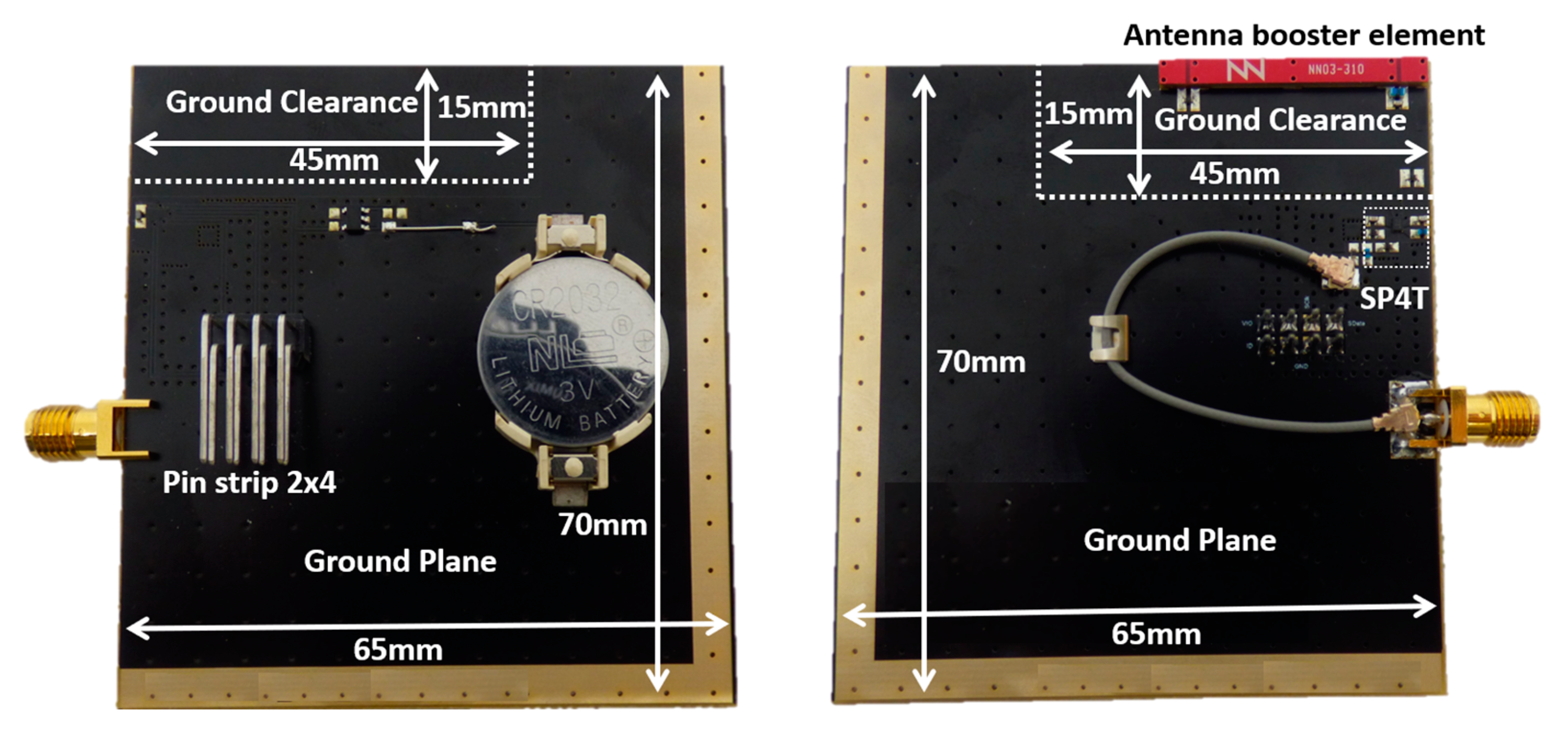
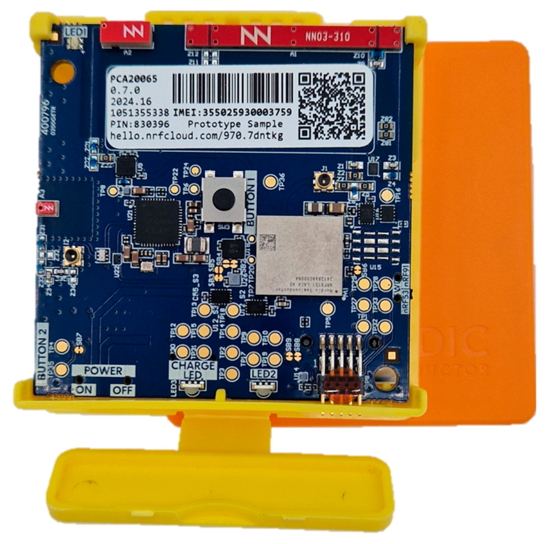
:1. Introduction
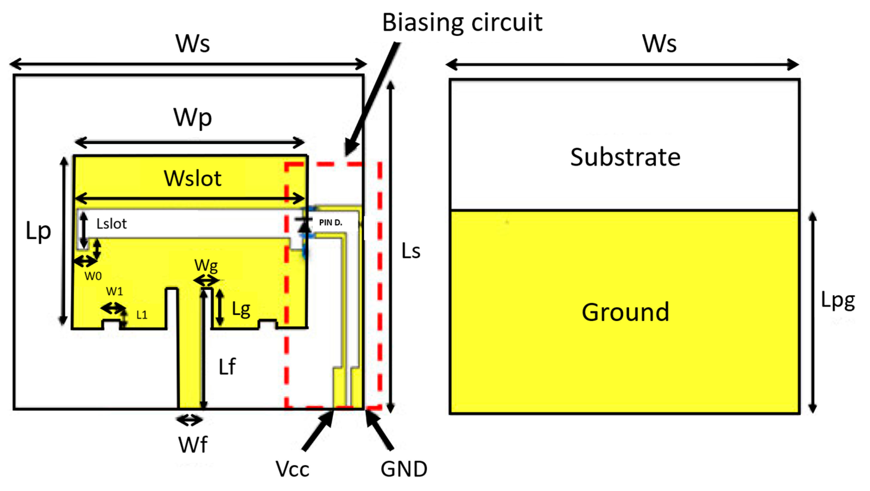
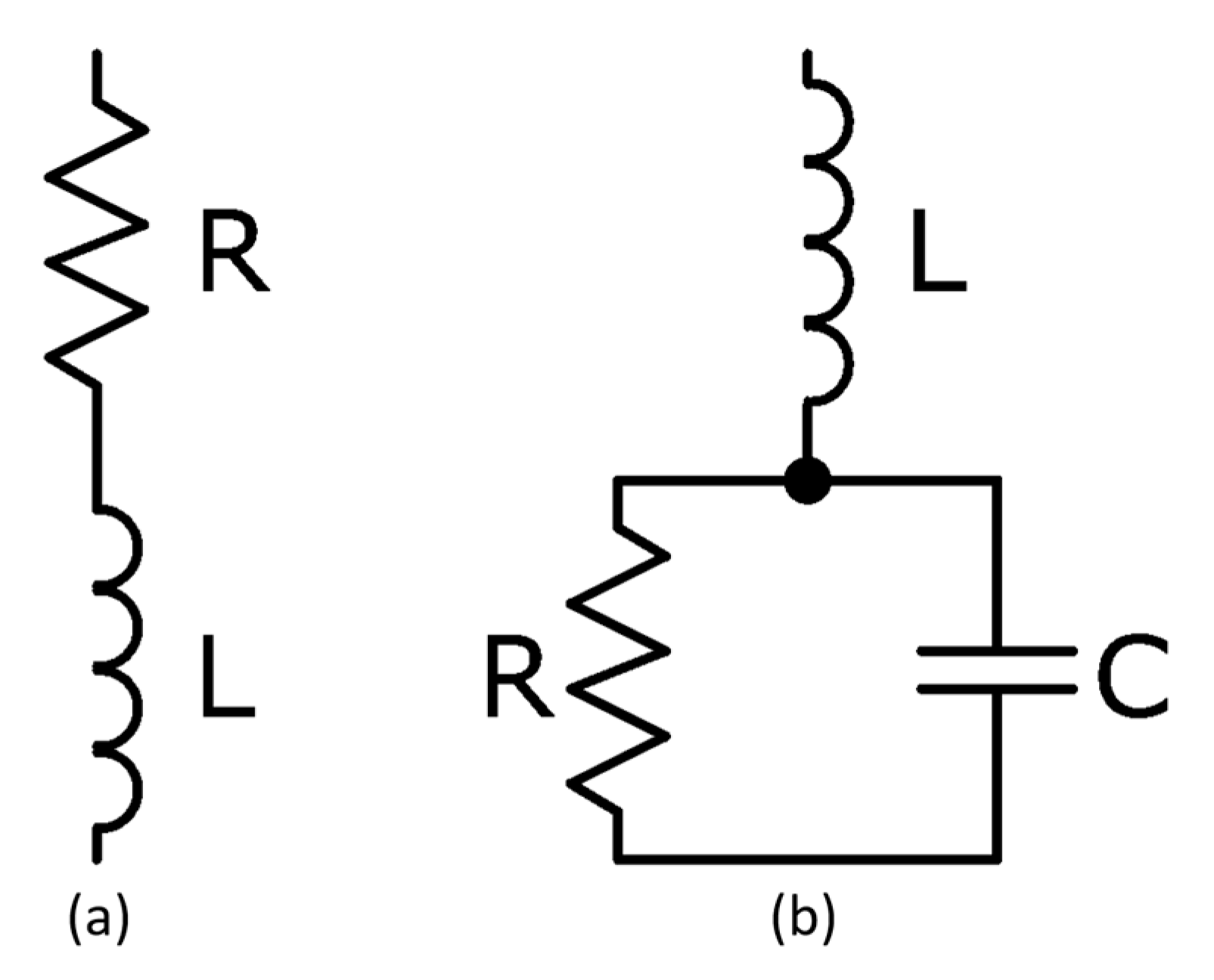
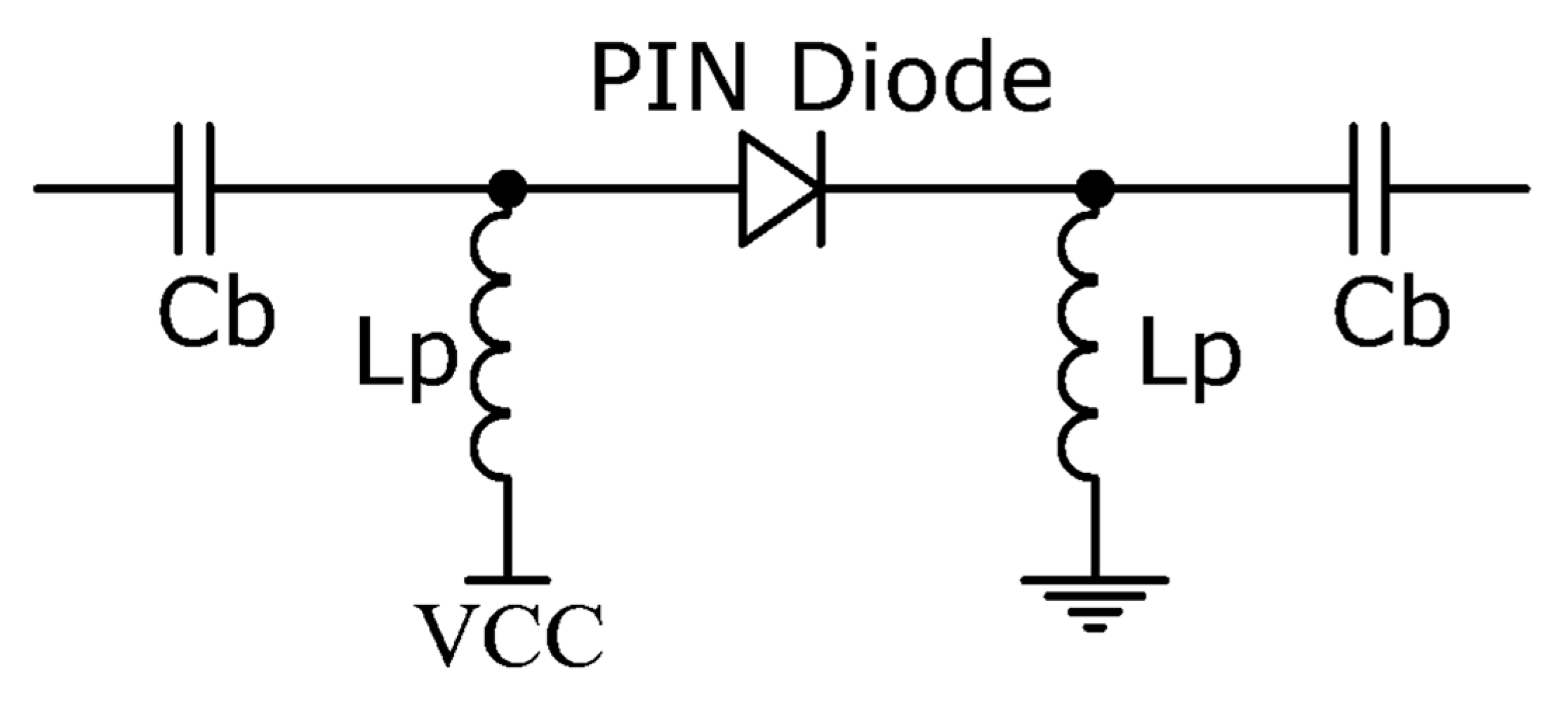
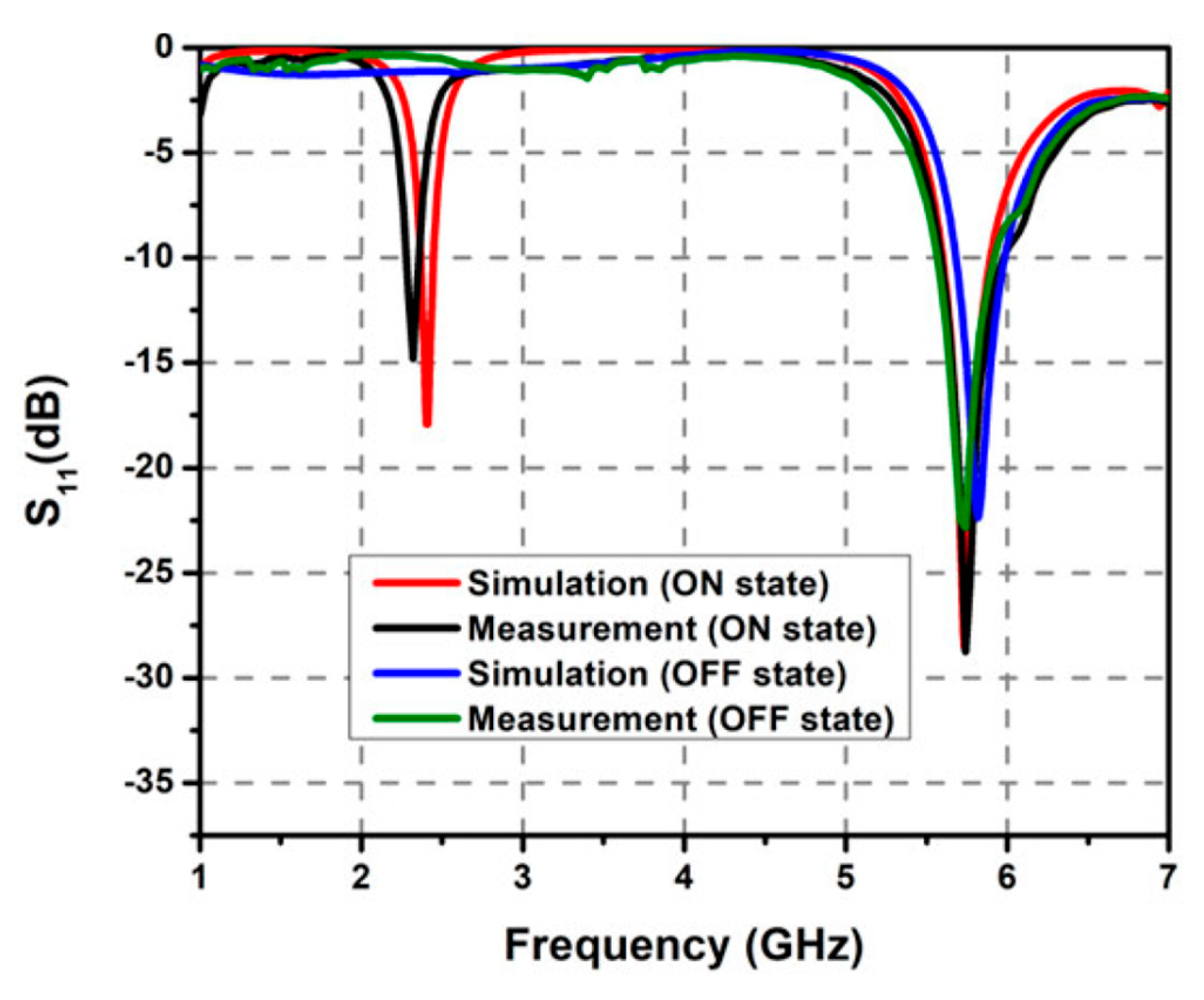
2. PIN Diode
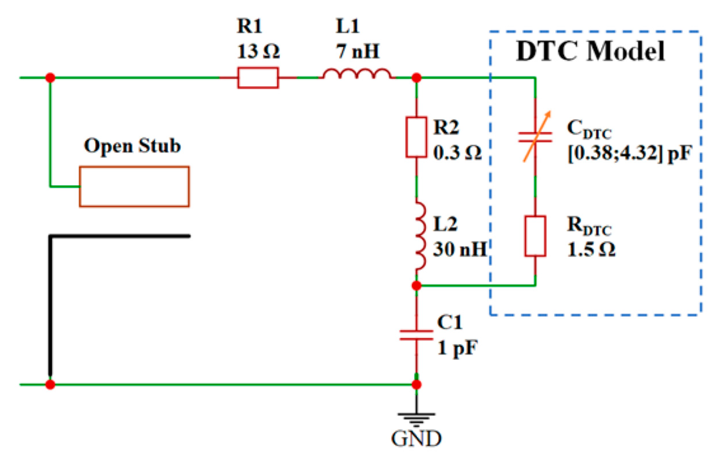
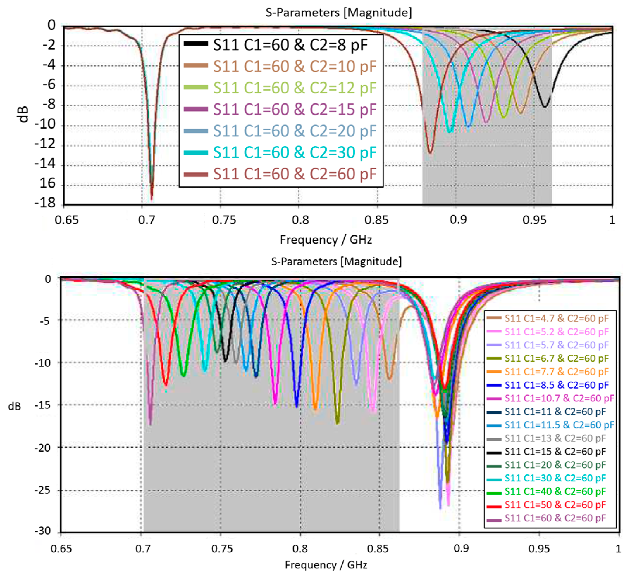
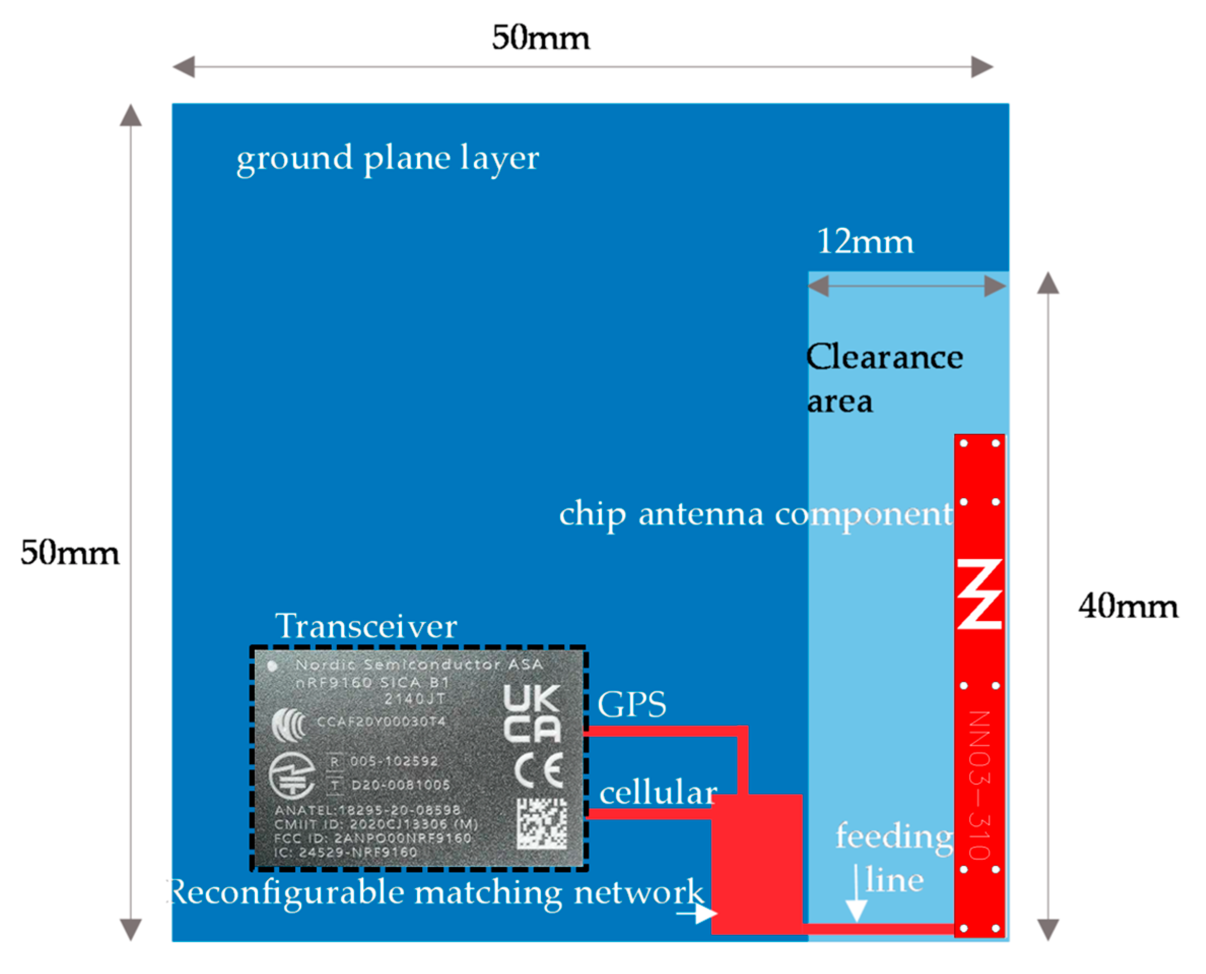
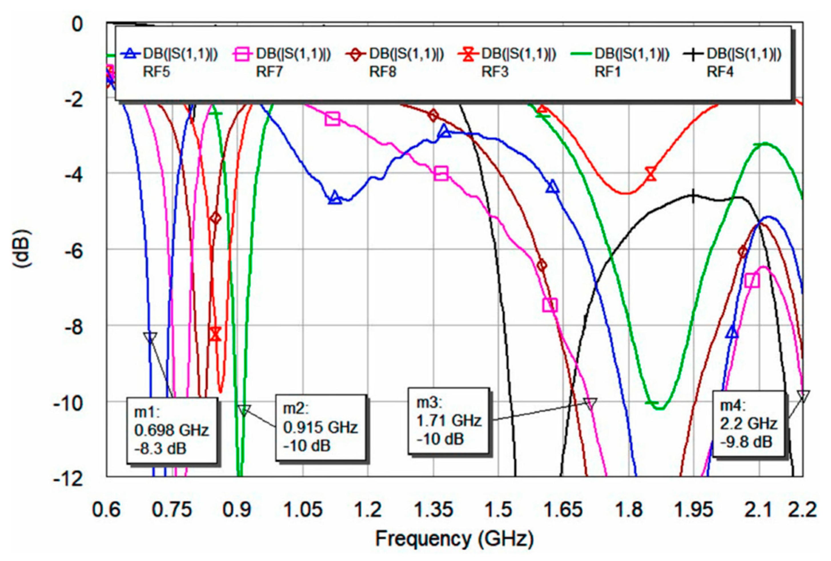
3. Digital Tunable Capacitors
4. Varactor Diodes
5. RF Switches: MEMS
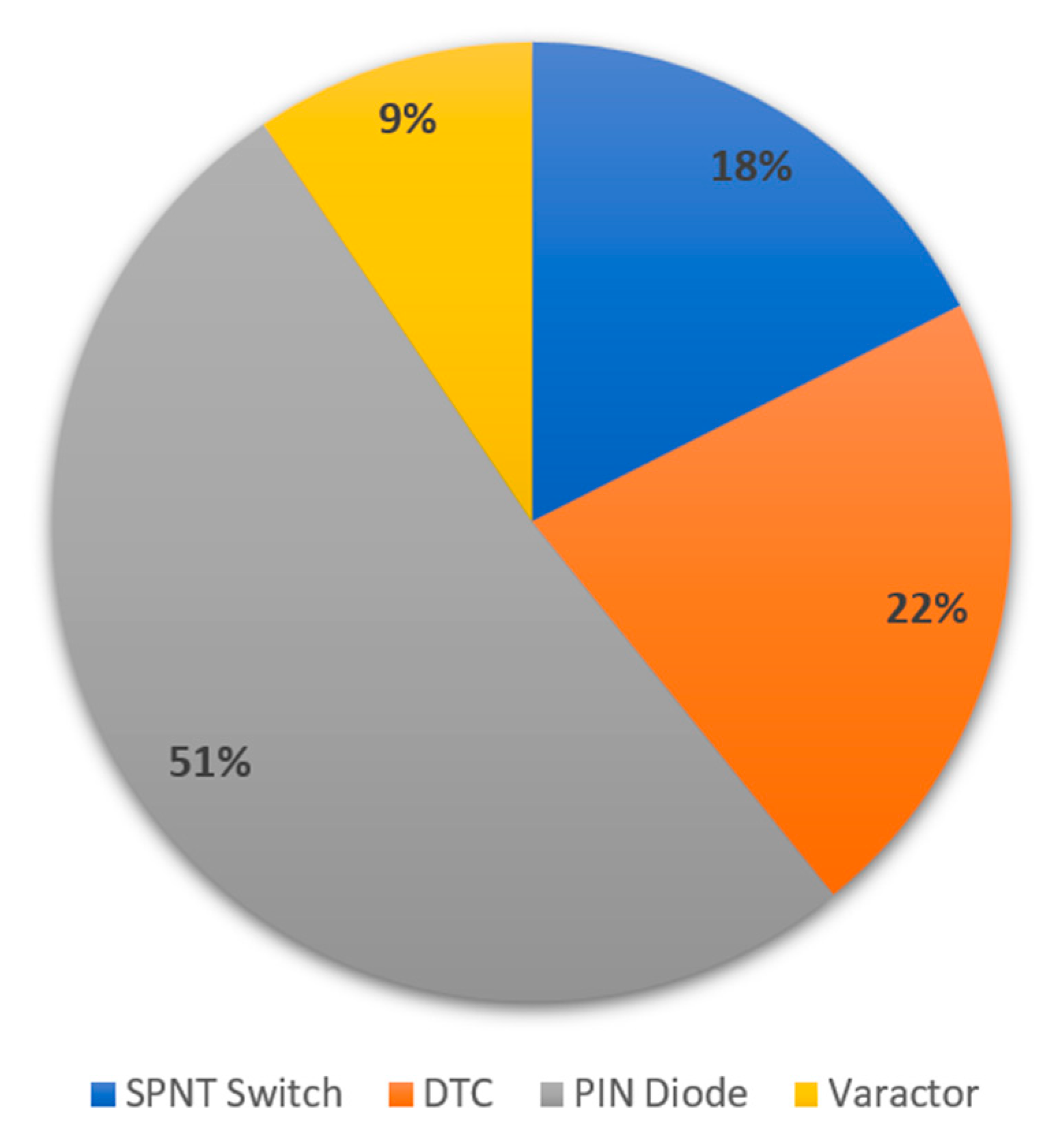
6. Discussion
7. Conclusions
Author Contributions
Funding
Data Availability Statement
Conflicts of Interest
References
- Patriotis, M.; Ayoub, F.N.; Christodoulou, C.G.; Chryssomallis, M.T. Reconfigurable Four-Sector Cube Antenna for IoT Devices. In Proceedings of the 2020 IEEE International Symposium on Antennas and Propagation and North American Radio Science Meeting, Montreal, QC, Canada, 5–10 July 2020; pp. 1815–1816. [Google Scholar] [CrossRef]
- Santamaria, L.; Ferrero, F.; Lizzi, L. Radiation Pattern Agile Antenna for Smart IoT Gateways. In Proceedings of the 2018 IEEE International Symposium on Antennas and Propagation & USNC/URSI National Radio Science Meeting, Boston, MA, USA, 8–13 July 2018; pp. 977–978. [Google Scholar] [CrossRef]
- Amin, H.Y.; Chen, J.; Berg, M.; Pärssinen, A. Tunable Front-end Design with a Dual-band Antenna for Small Cellular Devices. In Proceedings of the 2019 13th European Conference on Antennas and Propagation (EuCAP), Krakow, Poland, 31 March–5 April 2019; pp. 1–5. [Google Scholar]
- Ciccia, S.; Giordanengo, G.; Vecchi, G. Energy Efficiency in IoT Networks: Integration of Reconfigurable Antennas in Ultra Low-Power Radio Platforms Based on System-on-Chip. IEEE Internet Things J. 2019, 6, 6800–6810. [Google Scholar] [CrossRef]
- Chen, Z.; Wong, H.; Xiang, J.; Liu, S.-Z. Polarization-Reconfigurable Antennas for Internet of Things. In Proceedings of the 2019 International Conference on Microwave and Millimeter Wave Technology (ICMMT), Guangzhou, China, 19–22 May 2019; pp. 1–3. [Google Scholar] [CrossRef]
- Zeng, Z.; Shen, S.; Zhong, X.; Li, X.; Tsui, C.-Y.; Bermak, A.; Murch, R.; Sanchez-Sinencio, E. Design of Sub-Gigahertz Reconfigurable RF Energy Harvester from −22 to 4 dBm With 99.8% Peak MPPT Power Efficiency. IEEE J. Solid-State Circuits 2019, 54, 2601–2613. [Google Scholar] [CrossRef]
- Janisha, R.S.; Vishnu, D.; Sheeba, O. A Study on Frequency Reconfigurable Antenna in Modern Communication Systems. In Proceedings of the 2020 Fourth International Conference on I-SMAC (IoT in Social, Mobile, Analytics and Cloud) (I-SMAC), Palladam, India, 7–9 October 2020; pp. 318–321. [Google Scholar] [CrossRef]
- Devi, P.K.; Sujatha, M.; Prasath, J.A. Design of Reconfigurable Integrated patch antenna in ISM band for IoT applications. In Proceedings of the 2020 7th International Conference on Smart Structures and Systems (ICSSS), Chennai, India, 15–18 July 2020; pp. 1–4. [Google Scholar] [CrossRef]
- Leszkowska, L.; Czeleń, M.; Rzymowski, M.; Nyka, K.; Kulas, Ł. Miniaturized and Lightweight ESPAR Antenna for WSN and IoT Applications. In Proceedings of the 2024 18th European Conference on Antennas and Propagation (EuCAP), Glasgow, UK, 17–22 March 2024; pp. 1–4. [Google Scholar] [CrossRef]
- Yahya, M.S.; Soeung, S.; Rahim, S.K.A.; Musa, U.; Ba Hashwan, S.S.; Haque, M.A. Machine Learning-Optimized Compact Frequency Reconfigurable Antenna With RSSI Enhancement for Long-Range Applications. IEEE Access 2024, 12, 10970–10987. [Google Scholar] [CrossRef]
- Awan, W.A.; Hussain, Q.; Abbas, A.; Sufian, A.; Hussain, N.; Lee, S.; Kim, N. Compact Size Frequency-Agile Antenna Enabling Multi-Mode Functionality for Internet of Things Applications. In Proceedings of the 2024 18th European Conference on Antennas and Propagation (EuCAP), Glasgow, UK, 17–22 March 2024; pp. 1–3. [Google Scholar] [CrossRef]
- Alwahishi, R.; Ali, M.M.M.; Elzwawi, G.H.; Denidni, T.A. Beam-Switching Antenna Using Reconfigurable Intelligent Frequency Selective Surfaces for Internet of Things Applications. IEEE Internet Things J. 2024, 11, 4152–4162. [Google Scholar] [CrossRef]
- Arboleda, M.B.; Shamim, A. 3D Spatially Reconfigurable Circularly Polarized Antenna in Package with Embedded Electronics. In Proceedings of the 2024 18th European Conference on Antennas and Propagation (EuCAP), Glasgow, UK, 17–22 March 2024; pp. 1–4. [Google Scholar] [CrossRef]
- Ram, M.A.M.; Dey, S. A 3-bit Intelligent Reflective Surface with Reconfigurable Phase States, Polarization Insensitivity and Angular Stability for Wi-Fi and IoT applications. In Proceedings of the 2024 IEEE Wireless Antenna and Microwave Symposium (WAMS), Visakhapatnam, India, 29 Febraury–3 March 2024; pp. 1–5. [Google Scholar] [CrossRef]
- Subashree, V.; Hemanth, G.; Jagan, M. Developing a Biomedical Circular Patch Antenna with a Low Sar Content. In Proceedings of the 2024 2nd International Conference on Computer, Communication and Control (IC4), Indore, India, 8–12 October 2024; pp. 1–6. [Google Scholar] [CrossRef]
- Sennesael, J.; Kapusuz, K.Y.; Lemey, S.; Van Torre, P.; Rogier, H. Compact Reconfigurable Matching Network for Antenna Detuning Mitigation in Smart Surfaces. In Proceedings of the 2024 IEEE International Microwave Filter Workshop (IMFW), Cocoa Beach, FL, USA, 21–23 February 2024; pp. 72–74. [Google Scholar] [CrossRef]
- Wang, Z.; Dong, Y. Novel Pattern Reconfigurable Epsilon-Near-Zero (ENZ) Antenna for Intelligent IoT Communication Applications. IEEE Internet Things J. 2024, 11, 22364–22375. [Google Scholar] [CrossRef]
- Wu, C.; Ma, Y.; Venkatesh, S.; Mehlman, Y.; Ozatay, M.; Wagner, S.; Sturm, J.C.; Verma, N. A Monolithically Integrable Reconfigurable Antenna Based on Large-Area Electronics. IEEE J. Solid-State Circuits 2024, 59, 1475–1485. [Google Scholar] [CrossRef]
- Inserra, D.; Li, G.; Dai, J.; Shi, J.; Wen, G.; Li, J.; Huang, Y. Dual-Orthogonal Polarization Amplifying Reconfigurable Intelligent Surface With Reflection Amplifier Based on Passive Circulator. IEEE Trans. Microw. Theory Tech. 2024, 71, 4383–4394. [Google Scholar] [CrossRef]
- Sennesael, J.; Kapusuz, K.Y.; Lemey, S.; Van Torre, P.; Rogier, H. Compact AFSIW Antenna With Integrated Digitally Controlled Impedance Tuner for Smart Surfaces. IEEE Trans. Circuits Syst. II Express Briefs 2024, 71, 1111–1115. [Google Scholar] [CrossRef]
- Tam, S.-W.; Razzaghi, A.; Wong, A.; Narravula, S.; Xu, W.; Loo, T.; Kambale, A.; Lowrance, A.; Carnu, O.; Lin, Y.; et al. A 28 nm CMOS Dual-Band Concurrent WLAN and Narrow Band Transmitter With On-Chip Feedforward TX-to-TX Interference Cancellation Path for Low Antenna-to-Antenna Isolation in IoT Devices. IEEE J. Solid-State Circuits 2024, 59, 1301–1311. [Google Scholar] [CrossRef]
- IEEE.org. Available online: https://ieeexplore.ieee.org/Xplore/home.jsp (accessed on 14 June 2024).
- MDPI. Available online: https://www.mdpi.com/about/journals (accessed on 14 June 2024).
- Dalal, K.; Singh, T.; Singh, P.K. Multiband reconfigurable antennas for future wireless communication systems. Indian J. Radio Space Phys. 2020, 49, 79–97. [Google Scholar]
- Mohamadzade, B.; Simorangkir, R.B.V.B.; Maric, S.; Lalbakhsh, A.; Esselle, K.P.; Hashmi, R.M. Recent Developments and State of the Art in Flexible and Conformal Reconfigurable Antennas. Electronics 2020, 9, 1375. [Google Scholar] [CrossRef]
- Zhang, H.-B.; Ban, Y.-L.; Qiang, Y.-F.; Guo, J.; Yu, Z.-F. Reconfigurable Loop Antenna With Two Parasitic Grounded Strips for WWAN/LTE Unbroken-Metal-Rimmed Smartphones. IEEE Access 2017, 5, 4853–4858. [Google Scholar] [CrossRef]
- Kingsly, S.; Thangarasu, D.; Kanagasabai, M.; Alsath, M.G.N.; Thipparaju, R.R.; Palaniswamy, S.K.; Sambandam, P.; Selvam, Y.P.; Subbaraj, S. Multiband Reconfigurable Filtering Monopole Antenna for Cognitive Radio Applications. IEEE Antennas Wirel. Propag. Lett. 2018, 17, 1416–1420. [Google Scholar] [CrossRef]
- Ullah, S. A Tunable Microstrip Planar Antenna using Truncated Ground Plane for WiFi/LTE2500/WiMAX/5G/C, Ku, K-Band Wireless Applications. Int. J. Electr. Eng. Appl. Sci. (IJEEAS) 2019, 2, 77–84. Available online: https://ijeeas.utem.edu.my/ijeeas/article/view/5059 (accessed on 26 May 2024).
- Vamseekrishna, A.; Madhav, B.T.P.; Anilkumar, T.; Reddy, L.S.S. An IoT Controlled Octahedron Frequency Reconfigurable Multiband Antenna for Microwave Sensing Applications. IEEE Sens. Lett. 2019, 3, 3502204. [Google Scholar] [CrossRef]
- Hussain, N.; Awan, W.A.; Naqvi, S.I.; Ghaffar, A.; Zaidi, A.; Iftikhar, A.; Li, X.J. A Compact Flexible Frequency Reconfigurable Antenna for Heterogeneous Applications. IEEE Access 2020, 8, 173298–173307. [Google Scholar] [CrossRef]
- Singh, P.P.; Goswami, P.K.; Sharma, S.K.; Goswami, G. Frequency Reconfigurable Multiband Antenna for IoT Applications in WLAN, Wi-Max, and C-Band. Prog. Electromagn. Res. C 2020, 102, 149–162. [Google Scholar] [CrossRef]
- Haydhah, S.A.; Ferrero, F.; Lizzi, L.; Sharawi, M.S.; Zerguine, A. A Multifunctional Compact Pattern Reconfigurable Antenna With Four Radiation Patterns for Sub-GHz IoT Applications. IEEE Open J. Antennas Propag. 2021, 2, 613–622. [Google Scholar] [CrossRef]
- Sreelakshmi, K.; Rao, G.S.; Kumar, M.N.V.S.S. A Compact Grounded Asymmetric Coplanar Strip-Fed Flexible Multiband Reconfigurable Antenna for Wireless Applications. IEEE Access 2020, 8, 194497–194507. [Google Scholar] [CrossRef]
- Khan, T.; Rahman, M.; Akram, A.; Amin, Y.; Tenhunen, H. A Low-Cost CPW-Fed Multiband Frequency Reconfigurable Antenna for Wireless Applications. Electronics 2019, 8, 900. [Google Scholar] [CrossRef]
- Abd, A.K.; Rasool, J.M.; Rahman, Z.-A.S.A.; Al-Yasir, Y.I.A. Design and Analysis of Novel Reconfigurable Monopole Antenna Using Dip Switch and Covering 5G-Sub-6-GHz and C-Band Applications. Electronics 2022, 11, 3368. [Google Scholar] [CrossRef]
- Dildar, H.; Althobiani, F.; Ahmad, I.; Khan, W.U.R.; Ullah, S.; Mufti, N.; Ullah, S.; Muhammad, F.; Irfan, M.; Glowacz, A. Design and Experimental Analysis of Multiband Frequency Reconfigurable Antenna for 5G and Sub-6 GHz Wireless Communication. Micromachines 2021, 12, 32. [Google Scholar] [CrossRef] [PubMed]
- SUllah, S.; Ullah, S.; Ahmad, I.; Khan, W.U.R.; Ahmad, T.; Habib, U.; Albreem, M.A.; Alsharif, M.H.; Uthansakul, P. Frequency Reconfigurable Antenna for Portable Wireless Applications. Comput. Mater. Contin. 2021, 68, 1546–2226. [Google Scholar] [CrossRef]
- Mahlaoui, Z.; Antonino-Daviu, E.; Ferrando-Bataller, M. Radiation Pattern Reconfigurable Antenna for IoT Devices. Int. J. Antennas Propag. 2021, 2021, 1–13. [Google Scholar] [CrossRef]
- Kumar, J.; Basu, B.; Talukdar, F.A.; Nandi, A. Stable-multiband frequency reconfigurable antenna with improved radiation efficiency and increased number of multiband operations. IET Microw. Antennas Propag. 2019, 13, 642–648. [Google Scholar] [CrossRef]
- Al-Fadhali, N.; Majid, H.A.; Omar, R.; Dahlan, S.H.; Ashyap, A.Y.I.; Shah, S.M.; Rahim, M.K.A.; Esmail, B.A.F. Substrate integrated waveguide cavity backed frequency reconfigurable antenna for cognitive radio applies to internet of things applications. Int. J. RF Microw. Comput.-Aided Eng. 2019, 30. [Google Scholar] [CrossRef]
- Abutarboush, H.F.; Shamim, A. A Reconfigurable Inkjet-Printed Antenna on Paper Substrate for Wireless Applications. IEEE Antennas Wirel. Propag. Lett. 2018, 17, 1648–1651. [Google Scholar] [CrossRef]
- Chen, Y.; Zhang, L.; He, Y.; Li, W.; Wong, S.-W. A Pattern Reconfigurable SIW Horn Antenna Realized by PIN Diode Switches. In Proceedings of the 2021 Computing, Communications and IoT Applications (ComComAp), Shenzhen, China, 26–28 November 2021; pp. 112–115. [Google Scholar] [CrossRef]
- Jarchavi, S.M.R.; Shabbir, M.; Alibakhshikenari, M.; Falcone, F.; Limiti, E. Design of a UWB/Tri-Band Reconfigurable Flexible Antenna for IoT Applications. In Proceedings of the 2022 16th European Conference on Antennas and Propagation (EuCAP), Madrid, Spain, 27 March–1 April 2022; pp. 1–4. [Google Scholar] [CrossRef]
- Patriotis, M.; Ayoub, F.N.; Christodoulou, C.G. Four-Element Beam Switching Antenna for Compact IoT Devices. In Proceedings of the 2020 14th European Conference on Antennas and Propagation (EuCAP), Copenhagen, Denmark, 15–20 March 2020; pp. 1–4. [Google Scholar] [CrossRef]
- Chilukuri, S.; Rangaiah, Y.P.; Lokam, A.; Dahal, K. A Multi-Band Frequency and Pattern Reconfigurable Antenna for Wi-Fi/WiMAX and WLAN Applications: Frequency and Pattern Reconfigurable Antenna. In Proceedings of the 2018 9th International Conference on Mechanical and Aerospace Engineering (ICMAE), Budapest, Hungary, 10–13 July 2018; pp. 208–212. [Google Scholar] [CrossRef]
- Santamaria, L.; Ferrero, F.; Staraj, R.; Lizzi, L. Slot-Based Pattern Reconfigurable ESPAR Antenna for IoT Applications. IEEE Trans. Antennas Propag. 2021, 69, 3635–3644. [Google Scholar] [CrossRef]
- Zhou, S.-G.; Huang, G.-L.; Liu, H.-Y.; Lin, A.-S.; Sim, C.-Y.-D. A CPW-Fed Square-Ring Slot Antenna with Reconfigurable Polarization. IEEE Access 2018, 6, 16474–16483. [Google Scholar] [CrossRef]
- Sam, P.T.; Doondi, K.J.; Nesasudha, M. Concentric Circular Discs Reconfigurable Antenna for Internet of Things Applications at 2.45 GHz Band. In Proceedings of the 2020 IEEE Recent Advances in Intelligent Computational Systems (RAICS), Thiruvananthapuram, India, 3–5 December 2020; pp. 175–177. [Google Scholar] [CrossRef]
- Ja, H.A.; Ahmad, M.Y.; Shah, N.M.; Izam, T.F.T.M.N. Frequency Reconfigurable Shorting-Pin Loaded Rectenna for Smart Living. In Proceedings of the 2019 IEEE Asia-Pacific Microwave Conference (APMC), Singapore, 10–13 December 2019; pp. 1452–1454. [Google Scholar] [CrossRef]
- Behera, D.; Mishra, D.; Behera, S.K.; Pandav, S.; Gorai, A.; Mohapatra, S.K. A Frequency and Pattern Reconfigurable Planar Antenna for IoT Applications. In Proceedings of the 2023 International Conference on Communication, Circuits, and Systems (IC3S), Bhubaneswar, India, 26–28 May 2023; pp. 1–4. [Google Scholar] [CrossRef]
- Bammidi, D.; Kota, C.B.R. Design and validation of frequency reconfigurable multiband antenna using varied current distribution method. Meas. Sens. 2023, 29, 100844. [Google Scholar] [CrossRef]
- Infineon Technologies AG. BAR50-02V. Available online: https://www.infineon.com/cms/en/product/rf/rf-diode/rf-pin-diode/antenna-switch/bar50-02v/ (accessed on 28 July 2024).
- Musa, U.; Shah, S.M.; Majid, H.A.; Mahadi, I.A.; A Rahim, M.K.; Yahya, M.S.; Abidin, Z.Z. Design and Implementation of Active Antennas for IoT-Based Healthcare Monitoring System. IEEE Access 2024, 12, 48453–48471. [Google Scholar] [CrossRef]
- Skyworks. Available online: https://www.skyworksinc.com/en/Products/Diodes/SMP1321-Series (accessed on 28 July 2024).
- Padmanathan, S.; Al-Hadi, A.A.; Elshirkasi, A.M.; Al-Bawri, S.S.; Islam, M.T.; Sabapathy, T.; Jusoh, M.; Akkaraekthalin, P.; Soh, P.J. Compact Multiband Reconfigurable MIMO Antenna for Sub- 6GHz 5G Mobile Terminal. IEEE Access 2022, 10, 60241–60252. [Google Scholar] [CrossRef]
- Anguera, J.; Andújar, A. Antenna Booster Technology for Wireless Communications; Institute of Engineering and Technology: Stevenage, UK, 2024; ISBN -13 978-1-83953-300-6. [Google Scholar]
- Anguera, J.; Andújar, A.; Leiva, J.L.; Massó, O.; Tonnesen, J.; Rindalsholt, E.; Brandsegg, R.; Gaddi, R. Reconfigurable Multiband Operation for Wireless Devices Embedding Antenna Boosters. Electronics 2021, 10, 808. [Google Scholar] [CrossRef]
- Trinh, L.H.; Ferrero, F.; Lizzi, L.; Staraj, R.; Ribero, J.-M. Reconfigurable Antenna for Future Spectrum Reallocations in 5G Communications. IEEE Antennas Wirel. Propag. Lett. 2016, 15, 1297–1300. [Google Scholar] [CrossRef]
- Ilvonen, J.; Valkonen, R.; Holopainen, J.; Viikari, V. Multiband Frequency Reconfigurable 4G Handset Antenna with MIMO Capability. Prog. Electromagn. Res. 2014, 148, 233–243. [Google Scholar] [CrossRef]
- del Barrio, S.C.; Foroozanfard, E.; Morris, A.; Pedersen, G.F. Tunable Handset Antenna: Enhancing Efficiency on TV White Spaces. IEEE Trans. Antennas Propag. 2017, 65, 2106–2111. [Google Scholar] [CrossRef]
- Houret, T.; Lizzi, L.; Ferrero, F.; Danchesi, C.; Boudaud, S. DTC-Enabled Frequency-Tunable Inverted-F Antenna for IoT Applications. IEEE Antennas Wirel. Propag. Lett. 2020, 19, 307–311. [Google Scholar] [CrossRef]
- Paola, C.D.; Barrio, S.C.D.; Zhang, S.; Morris, A.S.; Pedersen, G.F. MEMS Tunable Frame Antennas Enabling Carrier Aggregation at 600 MHz. IEEE Access 2020, 8, 98705–98715. [Google Scholar] [CrossRef]
- Asadallah, F.; Shehadeh, G.; Costantine, J.; Tawk, Y.; Eid, A.; Tentzeris, M.M. A Digitally Tuned Flexible Reconfigurable Antenna for IoT Devices. In Proceedings of the 2020 IEEE International Symposium on Antennas and Propagation and North American Radio Science Meeting, Montreal, QC, Canada, 5–10 July 2020; pp. 1803–1804. [Google Scholar] [CrossRef]
- Asadallah, F.A.; Costantine, J.; Tawk, Y.; Lizzi, L.; Ferrero, F.; Christodoulou, C.G. A digitally tuned reconfigurable patch antenna for IoT devices. In Proceedings of the 2017 IEEE International Symposium on Antennas and Propagation & USNC/URSI National Radio Science Meeting, San Diego, CA, USA, 9–14 July 2017; pp. 917–918. [Google Scholar] [CrossRef]
- Houret, T.; Lizzi, L.; Ferrero, F.; Danchesi, C.; Boudaud, S. Energy efficient reconfigurable antenna for ultra-low power IoT devices. In Proceedings of the 2017 IEEE International Symposium on Antennas and Propagation & USNC/URSI National Radio Science Meeting, San Diego, CA, USA, 9–14 July 2017; pp. 1153–1154. [Google Scholar] [CrossRef]
- Asadallah, F.A.; Costantine, J.; Tawk, Y. A digitally tuned reconfigurable semi-bowtie antenna for IoT devices. In Proceedings of the 12th European Conference on Antennas and Propagation (EuCAP 2018), London, UK, 9–13 April 2018; pp. 1–2. [Google Scholar] [CrossRef]
- Ramadan, A.H.; Asadallah, F.A.; Costantine, J.; Tawk, Y. A New Compact Digitally Tuned Filtenna. In Proceedings of the 2019 13th European Conference on Antennas and Propagation (EuCAP), Krakow, Poland, 31 March–5 April 2019; pp. 1–3. [Google Scholar]
- Asadallah, F.A.; Eid, A.; Shehadeh, G.; Costantine, J.; Tawk, Y.; Tentzeris, E.M. Digital Reconfiguration of a Single Arm 3-D Bowtie Antenna. IEEE Trans. Antennas Propag. 2021, 69, 4184–4188. [Google Scholar] [CrossRef]
- pSemi. UltraCMOS® Digitally Tunable Capacitor. Available online: https://www.psemi.com/products/rf-phase-amplitude-control/digital-tunable-capacitors-dtcs/pe64907 (accessed on 15 February 2021).
- Trinh, L.-H.; Ferrero, F. Multiband Frequency Tuneable Antennas for Selection Combining Strategy in White Space Applications. Appl. Sci. 2022, 12, 11062. [Google Scholar] [CrossRef]
- Ferrero, F.; Trinh, L.H. 868MHz Antenna Input Impedance Reconfiguration for IoT applications. In Proceedings of the 2022 IEEE Conference on Antenna Measurements and Applications (CAMA), Guangzhou, China, 14–17 November 2022; pp. 1–2. [Google Scholar] [CrossRef]
- Riaz, S.; Zhao, X. An Eight-Port Frequency Reconfigurable MIMO Slot Antenna with Multi-Band Tuning Characteristics. In Proceedings of the 2018 12th International Symposium on Antennas, Propagation and EM Theory (ISAPE), Hangzhou, China, 3–6 December 2018; pp. 1–4. [Google Scholar] [CrossRef]
- Han, S.; Wang, Z.; Dong, Y. Miniaturized Circularly Polarized Reconfigurable Capacitance-Loaded Patch Antenna. IEEE Antennas Wirel. Propag. Lett. 2024, 23, 1226–1230. [Google Scholar] [CrossRef]
- Habib, I.; Diallo, A.; Le-Thuc, P.; Staraj, R.; Ngom, B. Frequency reconfigurable dual band PIFA antenna for IoT and NB-IoT applications. In Proceedings of the 2023 IEEE Conference on Antenna Measurements and Applications (CAMA), Genoa, Italy, 15–17 November 2023; pp. 644–648. [Google Scholar] [CrossRef]
- Macom. MA4P7455-287T. Available online: https://www.macom.com/products/product-detail/MA4P7455-287T (accessed on 14 June 2024).
- Wang, Z.; Dong, Y.; Ning, Y. Frequency Reconfigurable SRR-Based Compact Antenna for IoT Application. In Proceedings of the 2020 IEEE Asia-Pacific Microwave Conference (APMC), Hong Kong, China, 10–13 November 2020; pp. 148–150. [Google Scholar] [CrossRef]
- Skyworks. Available online: https://www.skyworksinc.com/Products/Diodes/SMV2019-Series (accessed on 14 June 2024).
- Diallo, K.; Diallo, A.; Dioum, I.; Ouya, S.; Ribero, J.-M. Compact Reconfigurable Antenna for NB-IoT or LTE-M and MIMO LTE2500 Applications. In Proceedings of the 2020 International Workshop on Antenna Technology (iWAT), Bucharest, Romania, 25–28 February 2020; pp. 1–4. [Google Scholar] [CrossRef]
- Skyworks. Available online: https://www.skyworksinc.com/en/Products/Diodes/SMV2020-079LF (accessed on 14 June 2024).
- Grant, P.D.; Denhoff, M.W.; Mansour, R.R. A Comparison between RF MEMS Switches and Semiconductor Switches. In Proceedings of the 2004 International Conference on MEMS, NANO and Smart Systems (ICMENS’04), Banff, AB, Canada, 25–27 August 2004; pp. 515–521. [Google Scholar] [CrossRef]
- Positano, F.; Santamaria, L.; Staraj, R.; Lizzi, L. Low Profile Pattern Reconfigurable ESPAR for UAVs in IoT Applications. In Proceedings of the 2023 17th European Conference on Antennas and Propagation (EuCAP), Florence, Italy, 26–31 March 2023; pp. 1–4. [Google Scholar] [CrossRef]
- Ban, Y.-L.; Sun, S.-C.; Li, P.-P.; Li, J.L.-W.; Kang, K. Compact Eight-Band Frequency Reconfigurable Antenna for LTE/WWAN Tablet Computer Applications. IEEE Trans. Antennas Propag. 2014, 62, 471–475. [Google Scholar] [CrossRef]
- Santamaria, L.; Ferrero, F.; Staraj, R.; Lizzi, L. Electronically Pattern Reconfigurable Antenna for IoT Applications. IEEE Open J. Antennas Propag. 2021, 2, 546–554. [Google Scholar] [CrossRef]
- Mbock, T.; Santamaria, L.; Lizzi, L. Slot-based Pattern Reconfigurable Antenna for Adaptive and Energy-Efficient IoT Devices. In Proceedings of the 2021 IEEE Conference on Antenna Measurements & Applications (CAMA), Antibes Juan-les-Pins, France, 15–17 November 2021; pp. 595–596. [Google Scholar] [CrossRef]
- Leng, T.; Pan, K.; Zhou, X.; Li, Y.; Abdalla, M.A.; Hu, Z. Non-Volatile RF Reconfigurable Antenna on Flexible Substrate for Wireless IoT Applications. IEEE Access 2021, 9, 119395–119401. [Google Scholar] [CrossRef]
- Bichara, R.M.; Asadallah, F.A.-Z.; Awad, M.; Costantine, J. A Miniaturized Reconfigurable Antenna using Quantum Genetic Algorithm Optimization. In Proceedings of the 2021 IEEE International Symposium on Antennas and Propagation and USNC-URSI Radio Science Meeting (APS/URSI), Singapore, 4–10 December 2021; pp. 763–764. [Google Scholar] [CrossRef]
- Asadallah, F.A.; Khalek, H.A.; Modad, B.A.A.; Hosn, J.A.; Costantine, J.; Kanj, R.; Tawk, Y. A Miniaturized Reconfigurable UHF Antenna. In Proceedings of the 2018 IEEE International Symposium on Antennas and Propagation & USNC/URSI National Radio Science Meeting, Boston, MA, USA, 8–13 July 2018; pp. 295–296. [Google Scholar] [CrossRef]
- Mansour, A.M.; Mokhtar, B.; Gomah, K.; Marghany, K.; Abdelmonsef, A.; Rizk, M.R.M.; Shehata, N. Compact reconfigurable multi-size pixel antenna for cognitive radio networks and IoT environments. In Proceedings of the 2016 Loughborough Antennas & Propagation Conference (LAPC), Loughborough, UK, 14–15 November 2016; pp. 1–5. [Google Scholar] [CrossRef]
- Positano, F.; Gallo, L.G.; Santamaria, L.; Staraj, R.; Lizzi, L. High-Gain Wire-Patch Based Pattern Reconfigurable Antenna for IoT Applications. In Proceedings of the 2022 IEEE International Symposium on Antennas and Propagation and USNC-URSI Radio Science Meeting (AP-S/URSI), Denver, CO, USA, 10–15 July 2022; pp. 1476–1477. [Google Scholar] [CrossRef]
- Vaseem, M.; Su, Z.; Yang, S.; Shamim, A. Flexibility Assesment of Fully Inkjet-Printed Reconfigurable Antenna With VO 2 Switch. In Proceedings of the 2018 IEEE Indian Conference on Antennas and Propogation (InCAP), Hyderabad, India, 16–19 December 2018; pp. 1–2. [Google Scholar] [CrossRef]
- Cayan, A.M.; Basbug, S. Four-Way Reconfigurable Repeater with U-Slot Microstrip Antennas for Outdoor IoT Applications. In Proceedings of the 2022 11th International Conference on Renewable Energy Research and Application (ICRERA), Istanbul, Turkey, 18–21 September 2022; pp. 523–527. [Google Scholar] [CrossRef]
- Mohammed, A.L.S.; Thakur, A.; Ali, T. A Compact Reconfigurable Dual band mm-wave 5G Antenna. In Proceedings of the 2018 3rd International Conference on Communication and Electronics Systems (ICCES), Coimbatore, India, 15–16 October 2018; pp. 682–687. [Google Scholar] [CrossRef]
- Qazi, F.Z.; Rukmini, M.S.S.; Chidrawar, S.K. Performance of GSO algorithm with ANN by using Matlab for RF MEMS Reconfigurable Antenna. In Proceedings of the 2018 2nd International Conference on I-SMAC (IoT in Social, Mobile, Analytics and Cloud) (I-SMAC)I-SMAC (IoT in Social, Mobile, Analytics and Cloud) (I-SMAC), Palladam, India, 30–31 August 2018; pp. 258–261. [Google Scholar] [CrossRef]
- Kulkarni, S.; Yanamshetti, R. MEMS based circular microstrip patch antenna at 2.4GHz for Wi-Fi applications. In Proceedings of the 2017 International Conference on Electrical, Electronics, Communication, Computer, and Optimization Techniques (ICEECCOT), Mysuru, India,, 15–16 December 2017; pp. 1–4. [Google Scholar] [CrossRef]
- Chen, L.; Huang, Y.; Wang, H.; Zhou, H.; Liu, K. A Reconfigurable Metal Rim Antenna With Smallest Clearance for Smartphone Applications. IEEE Access 2022, 10, 112250–112260. [Google Scholar] [CrossRef]
- Qorvo. QPC8013Q—Qorvo. Available online: https://www.qorvo.com/products/p/QPC8013Q (accessed on 14 June 2024).
- Anguera, J.; Andujar, A.; Puente, C.R. Mateos Modular Multi-Stage Antenna System and Component for Wireless Communications. U.S. Patent 11,482,772, 25 October 2022. [Google Scholar]
- Garcia, E.; Andújar, A.; Pijoan, J.L.; Anguera, J. Reconfigurable Antenna Booster System for Multiband Operation in IoT Devices With an SP4T Switch. IEEE Open J. Antennas Propag. 2024; ahead of print. [Google Scholar] [CrossRef]
- Anguera, J.; Andújar, A.; Puente, C. Multiband Antenna Booster Architecture with a Single Switch. U.S. Patent Application No. 17/749,989, 24 November 2022. [Google Scholar]
- Qorvo. QM13345. Available online: https://store.qorvo.com/products/detail/qm13345-qorvo/627347/ (accessed on 14 June 2024).
- Nordicsemi. Nordic Thingy: 91 Prototyping Platform. Available online: https://www.nordicsemi.com/Products/Development-hardware/Nordic-Thingy-91 (accessed on 28 July 2024).
- Nordic Semiconductor. Available online: https://www.nordicsemi.com/ (accessed on 14 June 2024).
- Ignion—IoT Antenna Technololgy. Available online: https://ignion.io/ (accessed on 11 February 2021).
- Johanson Technology. IoT Multiband Antenna Solution. 2022. Available online: https://www.johansontechnology.com/downloads/iot-multiband-antenna-solution.pdf (accessed on 12 June 2024).
- Ignion. AN_NN03-310_Thingy91. 2023. Available online: https://ignion.io/files/AN_NN03-310_Thingy91.pdf (accessed on 12 June 2024).
- Taoglas. PCS.50.A. 2022. Available online: https://www.taoglas.com/datasheets/PCS.50.A.pdf (accessed on 12 June 2024).
- Kyocera AVX. EC646-01. 2023. Available online: https://datasheets.kyocera-avx.com/1004795-EC646-01.pdf (accessed on 12 June 2024).
- Abracon. Tunable Antenna for Global NB-IoT and LTE Coverage. 2020. Available online: https://abracon.com/uploads/resources/Tunable-Antenna-for-Global-NB-IoT-and-LTE-Coverage.pdf (accessed on 18 June 2024).
- LM2735-Q1 520-kHz and 1.6-MHz Space-Efficient Boost and SEPIC DC/DC Regulator. Available online: https://www.ti.com/lit/ds/symlink/lm2735-q1.pdf?ts=1719354050399&ref_url=https%253A%252F%252Feu.mouser.com%252F (accessed on 26 June 2024).


| Reconfigurable Antenna Technique | Description | Suitable for IoT Devices | Suitable for Small Devices | Cost | Complexity |
|---|---|---|---|---|---|
| Electrical | Uses electrical components: RF switches and PIN/varactor diodes to change antenna properties. | Yes: low-power consumption, compact design possible. | Yes: electrical components can be miniaturized for small devices. | Relatively low cost | Low to moderate: established technology with well-understood components. |
| Mechanical | Physically changes the shape of the antenna: motors, gears. | No: bulky mechanisms and motors consume significant amounts of power. | No: mechanisms are inherently bulky and not suitable for miniaturization. | Moderate to high cost | High: moving parts require complex design and fabrication. |
| Optical | Uses light to change the properties of the antenna: light-sensitive materials. | Potentially: fast reconfiguration, but power consumption for light source needs evaluation. | Potentially: miniaturization is possible depending on the light source, but research is ongoing. | Potentially high cost: emerging technology, potentially complex light source setups. | High: emerging technology with potentially complex light source setups and material control mechanisms. |
| Material | Uses materials that change properties in response to external stimuli: temperature, voltage, light. | Potentially: low-power possibilities depending on the material, but research is ongoing. | Potentially: material properties could be suitable for miniaturization, depending on the material. | Cost varies: it depends on material properties and the complexity of control mechanisms. | Moderate to high: depends on material properties and control mechanisms. Can range from relatively simple to complex. |
| Reference | Reconfiguration | Antenna Dimensions | Frequency of Operation | Multiband Compatibility |
|---|---|---|---|---|
| [51] | 3 PIN Diodes | 625 mm2 | 2.38 GHz, 2.48 GHz, 3.98 GHz, 4 GHz, 4.45 GHz, 6.99 GHz, 7.2 GHz, 8.25 GHz | Yes |
| [53] | 1 PIN Diode | 1804 mm2 | 2.4 GHz and 5.8 GHz | Yes |
| [55] | 2 PIN Diode | 18,000 mm3 | 0.8 GHz to 6 GHz | Yes |
| [68] | DTC | 3360 mm2 | 868 MHz, 915 MHz, 1 GHz, 1.8 GHz and 2.1 GHz | Yes |
| [70] | DTC | 1792 mm3 | 470 to 700 MHz | No |
| [71] | DTC | 360 mm2 | 820 to 960 MHz | No |
| [74] | 2 Varactor Diodes | 980 mm3 | 703–960 MHz | No |
| [76] | 2 Varactor Diodes | 9600 mm2 | 840 MHz to 950 MHz | No |
| [78] | 2 Varactor Diodes | 1242 mm3 | 700–900 MHz and 2500–2700 MHz | Yes |
| [95] | 1 SP4T Switch | 730 mm2 | 690–960 MHz and 1700–2700 MHz | Yes |
| [57] | 2 SP8T Switches | 90 mm3 | 698–960 MHz and 1710–2170 MHz | Yes |
| [98] | 1 SP4T Switch | 90 mm3 | 698–960 MHz and 1710–2170 MHz | Yes |
| Feature | Varactor | PIN Diode | Digital Tunable Capacitor | RF Switch: MEMS |
|---|---|---|---|---|
| Function | Variable capacitor | Resistance in on state (3 Ω [52] when the current is 10 mA), capacitance in off state (0.2 pF [52]) | Adjustable capacitance (circuit) | Connects/disconnects a switch. Low resistance in on state and low capacitance in off state (0.8 Ω and 145 fF [101]). |
| Construction | Similar to diodes (designed for capacitance variation) | Two doped regions (p-type and n-type) | Array of capacitors and switches | Microscopic mechanical switch |
| Control Signal | Continuously variable voltage | Voltage applied | Digital signal (binary) | Digital signal (binary) |
| Tuning Range | Fine-tuning | Wide range | Discrete values, typically for fine-tuning | Wide range |
| Current Handling | Limited | Can handle moderate currents | Limited (by capacitors) | Can handle moderate currents |
| Voltage needed | 0 up to 22 V + extra circuit voltage needed to transform from typical 3 V batteries to these high voltages. | 0 up to 100 V + extra circuit voltage needed to transform from 3 V batteries to these high voltages. | ~3 V compatible with batteries in IoT devices. | ~3 V compatible with batteries in IoT devices. |
| Power Consumption | >0.01 mW | 1 mW up to 110 mW | ~0.5 mW | ~0.5 mW |
Disclaimer/Publisher’s Note: The statements, opinions and data contained in all publications are solely those of the individual author(s) and contributor(s) and not of MDPI and/or the editor(s). MDPI and/or the editor(s) disclaim responsibility for any injury to people or property resulting from any ideas, methods, instructions or products referred to in the content. |
© 2024 by the authors. Licensee MDPI, Basel, Switzerland. This article is an open access article distributed under the terms and conditions of the Creative Commons Attribution (CC BY) license (https://creativecommons.org/licenses/by/4.0/).
Share and Cite
García, E.; Andújar, A.; Anguera, J. Overview of Reconfigurable Antenna Systems for IoT Devices. Electronics 2024, 13, 3988. https://doi.org/10.3390/electronics13203988
García E, Andújar A, Anguera J. Overview of Reconfigurable Antenna Systems for IoT Devices. Electronics. 2024; 13(20):3988. https://doi.org/10.3390/electronics13203988
Chicago/Turabian StyleGarcía, Elena, Aurora Andújar, and Jaume Anguera. 2024. "Overview of Reconfigurable Antenna Systems for IoT Devices" Electronics 13, no. 20: 3988. https://doi.org/10.3390/electronics13203988