Article

A Tunable Microstrip-to-Waveguide Transition for Emergency Satellite Communication Systems

1
School of Engineering, Chengdu College of University of Electronic Science and Technology of China, Chengdu 611731, China
2
School of Physical Science and Technology, Southwest Jiaotong University (SWJTU), Chengdu 611756, China
*
Author to whom correspondence should be addressed.
Electronics 2024, 13(22), 4370; https://doi.org/10.3390/electronics13224370
Submission received: 17 October 2024 / Revised: 3 November 2024 / Accepted: 6 November 2024 / Published: 7 November 2024
(This article belongs to the Special Issue Microwave Devices: Analysis, Design, and Application)

Abstract

:
A tunable microstrip-to-waveguide transition is proposed for the ground station of emergency satellite communication systems. The proposed transition, consisting of a microstrip, three matched patches, three waveguides, and three metal screws, can not only convert the microstrip’s TEM-dominated mode into the waveguide’s TE mode within the transmitting frequency band, but also possesses the ability to filter out the amplified noise signals within the receiving frequency band around 12.5 GHz. Importantly, by adjusting the screws’ lengths, it is feasible to change the suppression frequency within the receiving frequency band and keep a good match within the transmitting frequency band. The measured results demonstrate that the proposed transition has a return loss of over 10 dB from 14 to 14.5 GHz and an out-of-band suppression of over 20 dB, from 12.25 to 12.7 GHz, with a typical value of −48 dB around 12.55 GHz. This unique feature eliminates the need for additional waveguide filters that prevent the amplified noise signal, thereby contributing to the miniaturization of the ground station.

1. Introduction

With the trend of globalization, the importance of emergency satellite communication systems has become increasingly prominent, especially as regards natural disasters, wars, and other critical events [1,2,3,4,5]. To achieve outstanding performance for entire systems, we need to introduce innovative technologies to enhance the capabilities of their components including, but not limited to, filters [6,7,8], antennas [9,10,11], transitions, suitable transmission lines, or others. As the two important transmission lines, waveguides and microstrip lines are usually utilized in combination to enhance the performance of a system. The former can offer low-loss characteristics and the latter has the advantage of integration. Moreover, the transitions between them are especially important and extensively applied to microwave, millimeter wave, and terahertz fields [12,13,14,15,16,17].
Commonly, transitions offer the fundamental function to achieve mode transformation between integrated circuits and waveguides. In addition, they hold immense importance in enhancing the overall system’s performance, such as in bandwidth expansion [18,19,20,21,22,23,24,25], miniaturization [26,27,28,29,30], dual band operation [31], etc. Typically, the radial shaped probe, the defected ground slot, the radiation probe, or the complementary split ring resonators can be utilized to provide wideband performance [18,19,20,23]. Generally, there are several approaches to achieving miniaturization. One way involves reducing the physical dimensions of the transition itself [26], while another way is to design the transitions such that they are integrated with additional components such as filters and directional couplers [27,28]. It also is feasible to achieve system miniaturization by designing suitable transitions for miniaturized waveguides such as H-plane waveguides [29] and integrated waveguides [30]. The implementation of dual-band transitions, which can effectively perform the functions of two separate single-band ones, offers significant advantages in terms of reducing system costs [31]. Furthermore, the tuning screw is one of the common approaches to achieving the tunable functionin microwave devices. S. Wong et al. proposed dual- and triple-band tunable filters using screws [32]. P. Sanchez-Olivares et al. achieved a mechanically reconfigurable conformal array antenna by introducing tuning screws into the radial waveguide divider [33]. L. Polo-López et al. proposed a novel waveguide reflection-type phase shifter with tuning screws to construct a reconfigurable linear phased array antenna [34].
For the ground stations of emergency satellite communication systems, the transmitting terminal, the receiving terminal, and the antenna are connected by a duplexer. Hence, the amplified noise signals from the transmitting terminal can always result in a worse signal-to-noise ratio in the receiving terminal. For the conventional approach, an extra waveguide filter is used to suppress amplified noise signals but would enlarge the system size. In this paper, we propose a novel microstrip-to-waveguide transition that integrates the function of out-of-band suppression within the receiving frequency band, thus eliminating the need for an extra waveguide filter. Meanwhile, the out-of-band suppression frequency in the receiving frequency band is tunable by adjusting the length of the tuning screws.

2. Transition Design

In the ground station, the operating frequency band of the transmitting terminal is from 14 to 14.5 GHz, and that of the receiving terminal is from 12.25 to 12.75 GHz. When the transmitter works, it generates noise signals within the receiving frequency band. The noise signals inevitably transport to the receiving terminal by the duplexer because the duplexer cannot completely attenuate them. In order to enhance the suppression, in the conventional solution, an extra waveguide filter is introduced between the transition and the duplexer, as shown in Figure 1. In our design, the microstrip-to-waveguide transition located between the power amplifier and the duplexer integrates the out-of-band suppression function, and thus, the waveguide filter becomes unnecessary.
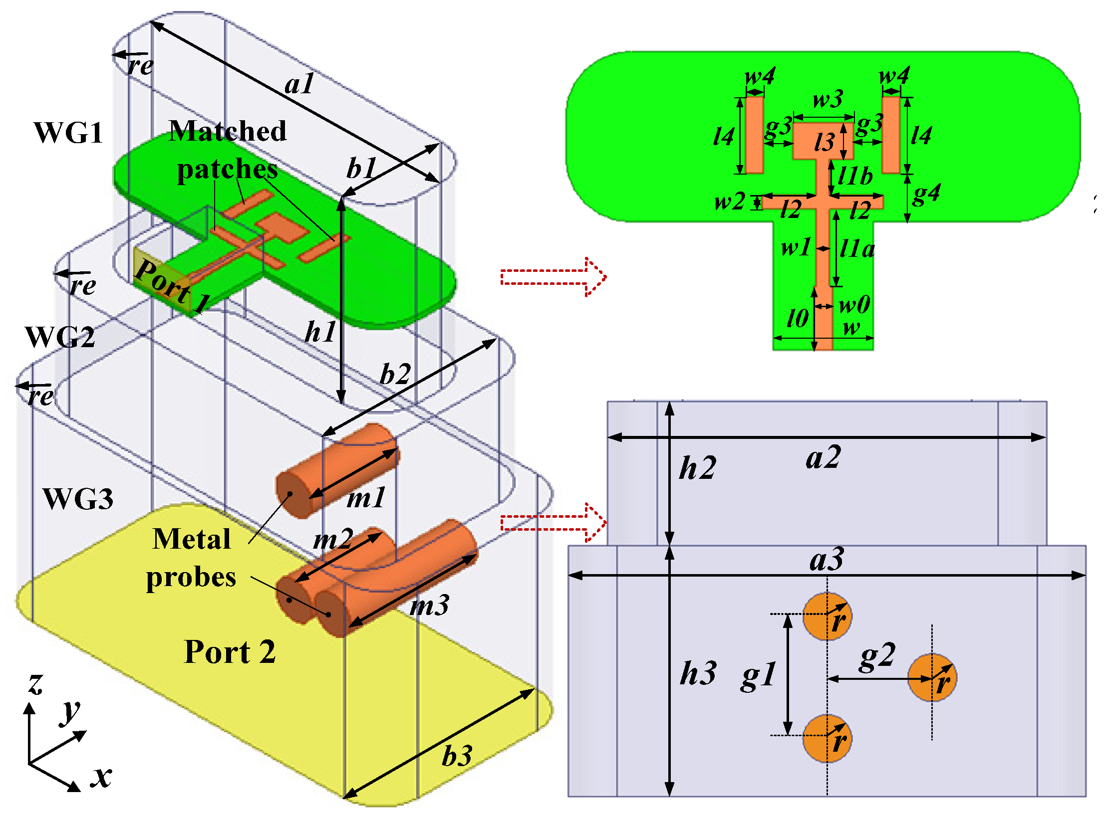
According to the microwave theory [35], a λ/2 open-ended transmission line can be regarded as a resonator. When the resonator is located along the E-plane of the waveguide, it obstructs the propagation of electromagnetic waves. Hence, to enhance suppression within the receiving frequency band, we use open-ended metal probes to construct the resonator, as shown in Figure 2. As λ/2 is much larger than the b3 of WG3, we utilize three metal probes instead of one metal probe, and its total length is determined by:
m 1 + m 2 + m 3 = λ / 2
λ = c / f  
where c is the speed of light in a vacuum and λ is wavelength at the receiving frequency band.
As shown in Figure 2, the proposed transition comprises a microstrip patch, three matched patches, three waveguides (WG1, WG2, WG3), and three metal probes. As we can see, three metal probes are introduced into WG3 to achieve out-of-band suppression within the receiving frequency band, thereby eliminating the extra waveguide filter and reducing the size of the device. Importantly, one can change the suppression frequency by adjusting the total length of the metal probes according to Equation (1). Furthermore, three matched patches and WG2 are used to compensate the match within the transmitting frequency band. Here, the microstrip utilizes Rogers Ro 4003(tm) dielectric, which is characterized by a relative permittivity of 3.55 and a loss tangent of 0.0027. The cavity shell is aluminum.
To achieve the desired performance, we employ the High Frequency Structure Simulator (HFSS) of ANSYS Electronics Desktop 2018.2 [36] to analyze the microstrip-to-waveguide transition. In the simulation, the solution type in the HFSS is set as “Modal”. The parameters are listed in Table 1.
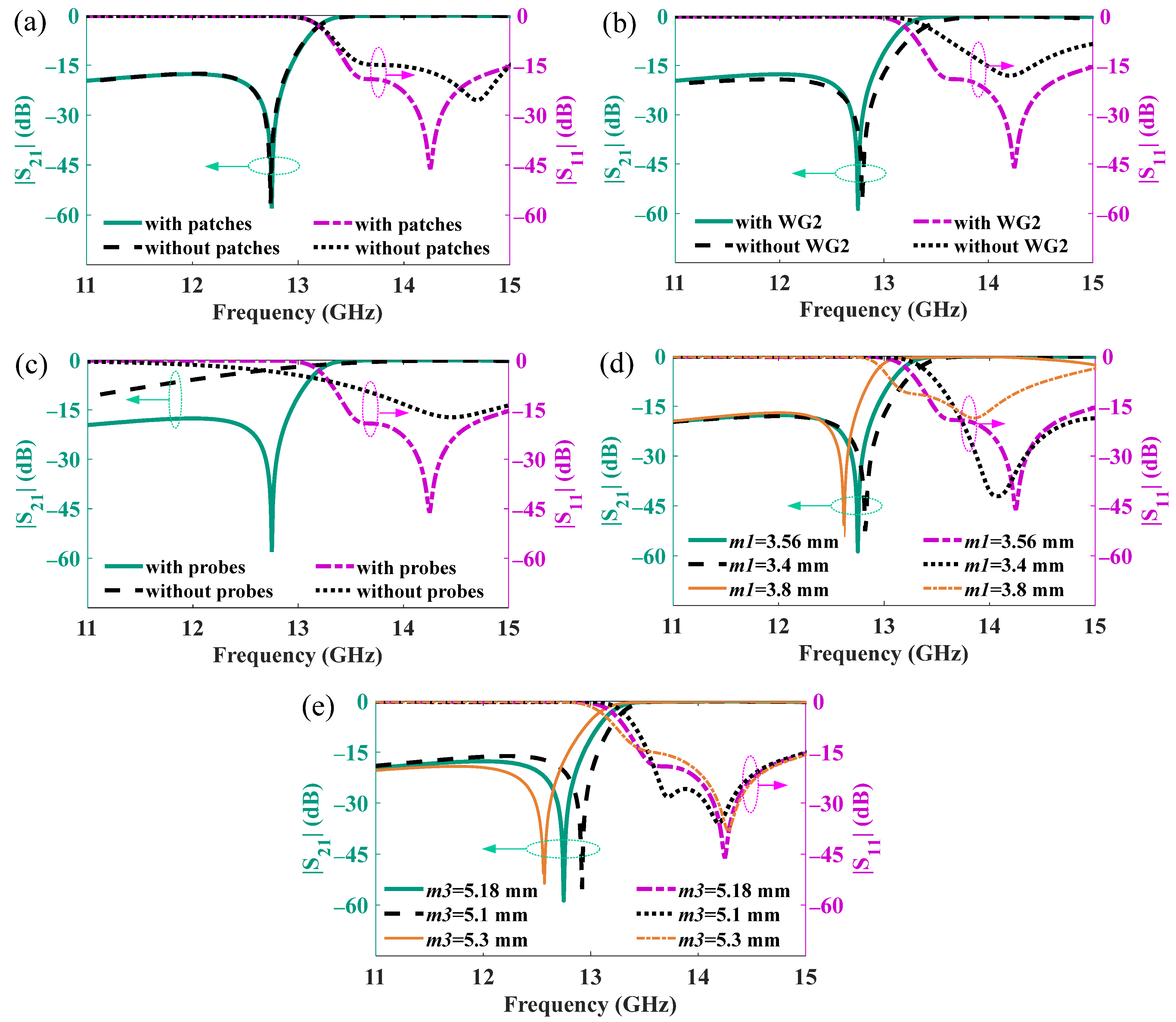
Figure 3a,b shows the S parameters of the transition without the three matched patches and WG2, respectively. It is clear that the patches and WG2 can enhance the match in the transmitting frequency band and hardly generate influence on suppression within the receiving frequency band. Figure 3c shows the S parameters of the transition without the three metal probes. The results clearly indicate that the three metal probes in WG3 can significantly improve out-of-band suppression within the receiving frequency band, especially with |S21| ~−55 dB at 12.75 GHz. Meanwhile, the length of the metal probes can change the suppression frequency at the receiving frequency band, as shown in Figure 3d,e. It is clear that increasing the probe length can lower the suppression frequency. A change in m1 or m2 would lead to a mismatch in the transmitting frequency band, while a change in m3 would slightly influence the passband characteristics. As a result, we can design a suitable m1, m2, and m3 to enhance the out-of-band suppression and then optimize the three patches and WG2 to enhance the match from 14 to 14.5 GHz.

3. Experiment Results and Discussion

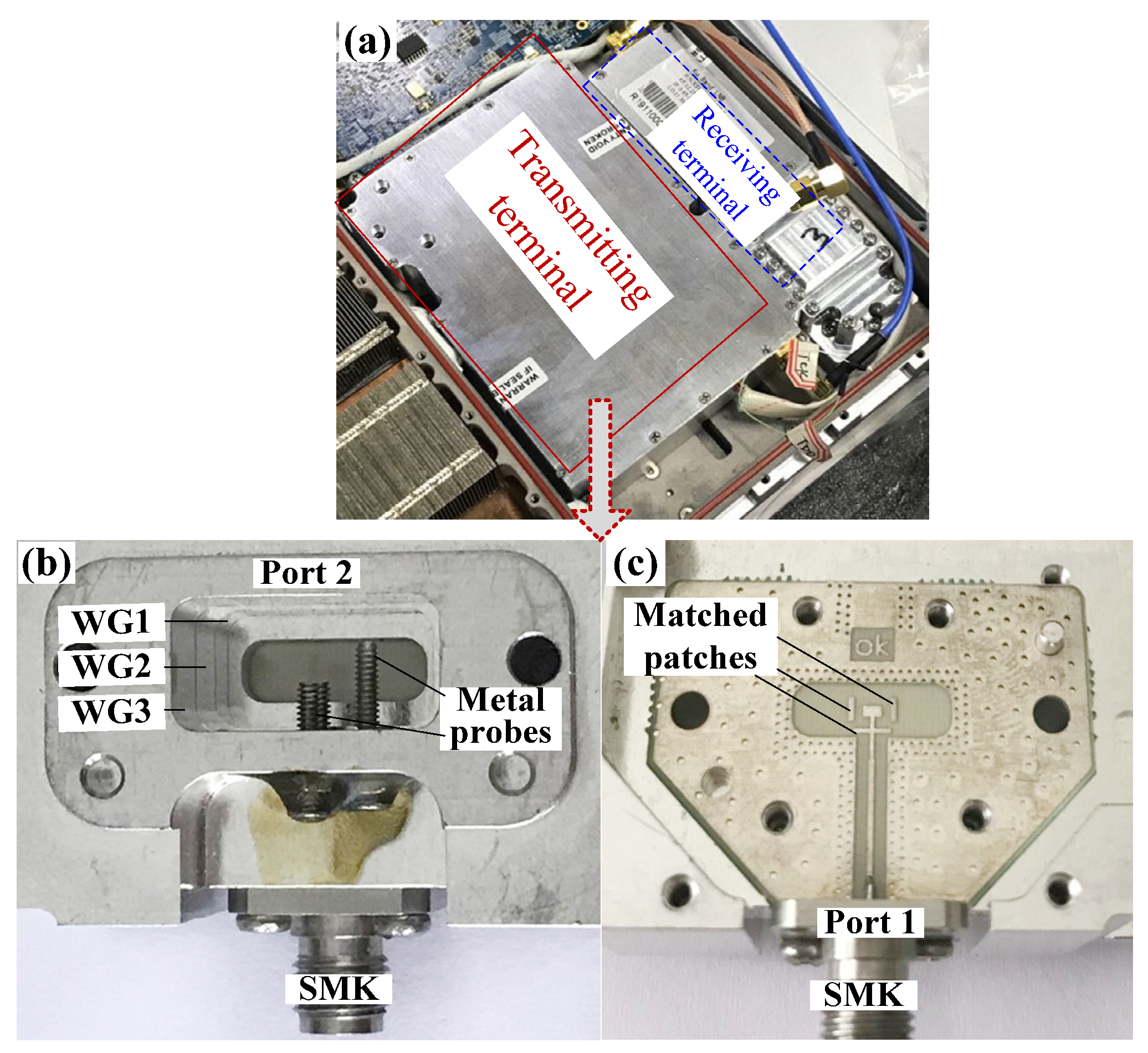
The ground station with the fabricated microstrip-to-waveguide transition is shown in Figure 4a. Figure 4b shows three waveguides with three screws, and Figure 4c shows the microstrip with three matched patches. Here, three tuning screws are used as the three metal probes for the following two reasons. Firstly, it can sharply reduce the fabrication difficulty and lower the cost. Secondly, it can achieve the tunability of suppression frequency within the receiving frequency band by easily adjusting the screws’ lengths.
We utilize the vector network analyzer (Rohde & Schwarz ZNB 40, from 10 MHz to 40 GHz) to measure the S parameters. Here, the microstrip of the transition is connected to a 2.92 coaxial connector (SMK) with 50 Ω impedance, while WG3 of the transition is connected to a waveguide-to-coaxial adapter. In the actual product, the microstrip is directly connected to a power amplifier without the coaxial connector, and thus, the type of connector does not impact its performance.
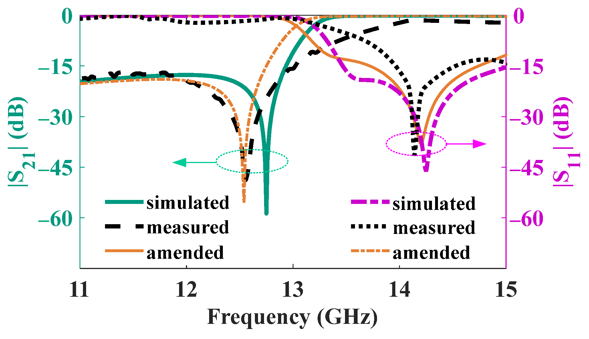
The measured and simulated |S21| and |S11| are shown in Figure 5. As we can see, the measured |S11| is less than −10 dB from 14 GHz to 14.5 GHz, typically ~−40 dB at 14.15 GHz. While the measured |S21| is less than −20 dB within the receiving frequency band of 12.25–12.75 GHz, with a typical value of −48 dB around 12.55 GHz. As we can see, there is a little deviation between the measured and simulated results. On the one hand, it can be caused by inevitable machining and measured errors. On the other hand, manual adjustment of deviation in m1, m2, and m3 can directly lead to discrepancies in the measurement. As shown in Figure 3d,e, when m1, (m2), or m3 increases, the transmission zero in the receiving frequency band decreases, which agrees well with the theoretical prediction from Equation (1). Figure 5 shows that the measured transmission zero is lower than simulated one, indicating that we should increase m1, (m2), or m3. Furthermore, reflection zero in the operating frequency band increases with the increasing of m3. Meanwhile, a large m1 (m2) would lead to mismatches in the operating frequency band, as the screws with m1 (m2) are located at the center of the E-plane, which has the strongest electric field. Hence, it is better to fine-tune m1 (m2) and coarsely adjust m3 to make the simulated results closer to the measured ones.
According to the above analysis, we further perform the simulation and thus obtain the amended results with m1 = m2 = 3.62 mm and m3 = 5.3 mm, as shown in Figure 5. The results indicate that the primary source of the discrepancy between the measured results and the simulated ones is derived from the difference in the screw lengths in measurement relative to the simulated ones.
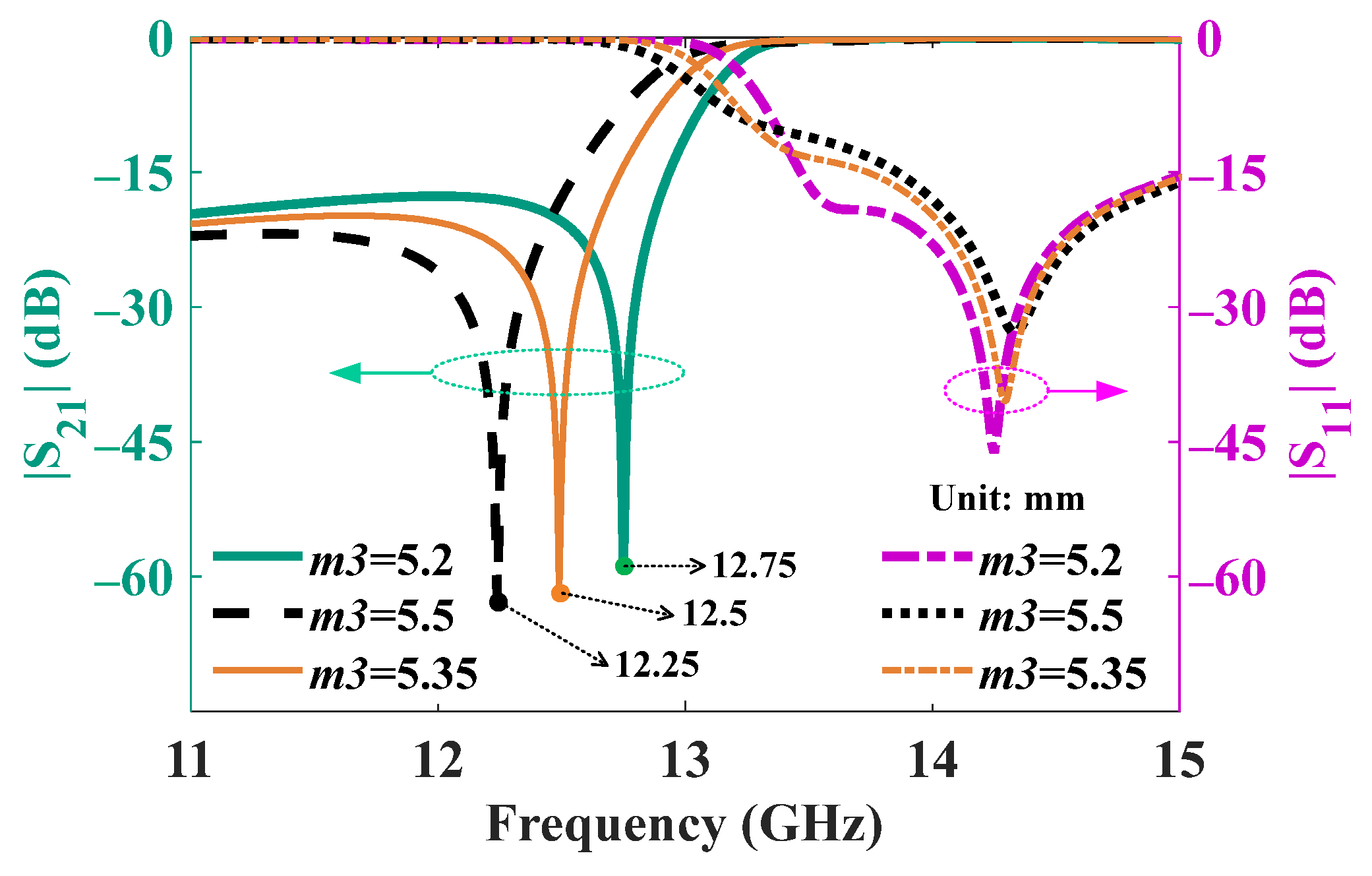
Furthermore, we obtain the simulated S parameters for different m3, as shown in Figure 6. As m3 changes from 5.5 mm to 5.2 mm, the suppression frequency ranges from 12.25 GHz to 12.75 GHz in the receiving frequency band, and |S11| can keep less than −10 dB within the transmitting frequency band from 14 GHz to 14.5 GHz. Though the measured results exhibit differences with the designed ones, the proposed transition has demonstrated its tunable capability to significantly enhance out-of-band suppression within the whole receiving frequency band.

4. Discussion

The comparison between the previous literature and this work is shown in Table 2. Compared to the previous transitions, the proposed microstrip-to-waveguide transition provides significantly greater out-of-band suppression. Meanwhile, we have introduced the tuning screw to demonstrate the effectiveness of tuning capability in a transition. Though the tuning screw is widely used in filters, antennas, and shifters [32,33,34], it is not common in transitions. This advantage helps prevent amplified noise signals around the receiving frequency band from entering the receiving terminal, and thus eliminates the need for additional waveguide filters. As the amplified noise signals are uncertainly located within the receiving frequency band, we need to enhance suppression through tuning. Meanwhile, as the amplified noise signal is usually narrowband, there is no need to increase noise suppression within the entire receiving frequency band.

5. Conclusions

In this paper, we propose a novel tunable microstrip-to-waveguide transition for the ground station of emergency satellite communication systems. Both simulated and measured results confirm that the transition can effectively suppress the amplified noise signals within the receiving frequency band. Importantly, tuning screw technology has been introduced into the proposed transition to achieve the tunability of the transmission zero in the receiving frequency band. This is particularly crucial in the actual debugging process, as the frequency of the amplified noise signals randomly distribute within the receiving frequency band. Specially, three tuning metal screws are incorporated to enhance the out-of-band suppression within the entire receiving frequency band of 12.25–12.75 GHz. In addition, in order to enhance the match in the transmitting frequency range of 14–14.5 GHz, three matched patches and three waveguides are involved in the transition. This work is instrumental in advancing the miniaturization of ground stations for emergency satellite communication systems. In the future, we will promote the system test of the ground station with the proposed microstrip-to-waveguide transition.

Author Contributions

Conceptualization, Y.X.; methodology, Y.X.; software, Y.X. and X.T.; formal analysis, Y.X. and D.G.; data curation, Y.X.; writing—original draft preparation, Y.X. and X.T.; writing—review and editing, Y.X., D.G. and X.T. All authors have read and agreed to the published version of the manuscript.

Funding

This work was supported by the School-Level Scientific Research Project of Chengdu College of University of Electronic Science and Technology of China (No. 2024-KXYJ-03), and the Sichuan Key Research and Development Program (No. 2022YFG0226), National Natural Science Foundation of China (No. 62301459).

Data Availability Statement

Dataset available on request from the authors.

Conflicts of Interest

The authors declare no conflicts of interest.

References

  1. Alagöz, F.; Gür, G. Energy efficiency and satellite networking: A holistic overview. Proc. IEEE 2011, 99, 1954. [Google Scholar] [CrossRef]
  2. Darwish, T.; Kurt, G.K.; Yanikomeroglu, H.; Bellemare, M.; Lamontagne, G. LEO satellites in 5G and beyond networks: A review from a standardization perspective. IEEE Access 2022, 10, 35040. [Google Scholar] [CrossRef]
  3. Yuan, D.; Qin, Y.; Wu, Z.; Shen, X. An emergency positioning system fusing GEO satellite Doppler observation and INS for SOTM. IEEE Trans. Instrum. Meas. 2021, 70, 8503804. [Google Scholar] [CrossRef]
  4. Guo, S.; Li, G.; Zheng, J.; Ren, Q.; Wu, Y.; Shen, G.; Yue, H. Integrated navigation and communication service for LEO satellites based on BDS-3 global short message communication. IEEE Access 2023, 11, 6623. [Google Scholar] [CrossRef]
  5. Leyva-Mayorga, I.; Soret, B.; Röper, M.; Wübben, D.; Matthiesen, B.; Dekorsy, A.; Popovski, P. Leo small-satellite constellations for 5G and beyond-5G communications. IEEE Access 2020, 8, 184955. [Google Scholar] [CrossRef]
  6. Tang, X.; Zang, Y.; Li, X.; Xu, C. A metamaterial bandpass filter with end-fire coaxial coupling. Electronics 2024, 13, 3158. [Google Scholar] [CrossRef]
  7. Li, S.; Yao, Y.; Cheng, X.; Yu, J. Design of a dual-band filter based on the band gap waveguide. Electronics 2024, 13, 3982. [Google Scholar] [CrossRef]
  8. Yang, L.; Zhu, X.; Gómez-García, R. High-order quasi-elliptic-type wideband bandpass filter with ultrabroad input-reflectionless stopband range. IEEE Microw. Wirel. Technol. Lett. 2023, 33, 655. [Google Scholar] [CrossRef]
  9. Rahmat-Samii, Y.; Densmore, A.C. Technology trends and challenges of antennas for satellite communication systems. IEEE Trans. Antennas Propag. 2015, 63, 1191–1204. [Google Scholar] [CrossRef]
  10. Yang, Z.; Browning, K.C.; Warnick, K.F. High-efficiency stacked shorted annular patch antenna feed for Ku-band satellite communications. IEEE Trans. Antennas Propag. 2016, 64, 2568. [Google Scholar] [CrossRef]
  11. Montori, S.; Cacciamani, F.; Gatti, R.V.; Sorrentino, R.; Arista, G.; Tienda, C.; Encinar, J.A.; Toso, G. A transportable reflectarray antenna for satellite Ku-band emergency communications. IEEE Trans. Antennas Propag. 2015, 63, 1393. [Google Scholar] [CrossRef]
  12. Topak, E.; Hasch, J.; Zwick, T. Compact topside millimeter-wave waveguide-to-microstrip transitions. IEEE Microw. Wirel. Compon. Lett. 2013, 23, 641. [Google Scholar] [CrossRef]
  13. Kim, J.; Choe, W.; Jeong, J. Submillimeter-wave waveguide-to-microstrip transitions for wide circuits/wafers. IEEE Trans. Terahertz Sci. Technol. 2017, 7, 440. [Google Scholar] [CrossRef]
  14. Liu, Z.; Xu, J.; Wang, W. Wideband transition from microstrip line-to-empty substrate-integrated waveguide without sharp dielectric taper. IEEE Microw. Wirel. Compon. Lett. 2019, 29, 20. [Google Scholar] [CrossRef]
  15. Xu, Z.; Xu, J.; Qian, C. Novel In-line microstrip-to-waveguide transition based on E-plane probe T-junction structure. IEEE Microw. Wirel. Compon. Lett. 2021, 31, 1051. [Google Scholar] [CrossRef]
  16. Wu, C.; Zhang, Y.; Li, Y.; Zhu, H.; Xiao, F.; Yan, B.; Xu, R. Millimeter-wave waveguide-to-microstrip inline transition using a wedge-waveguide iris. IEEE Trans. Microw. Theory Tech. 2022, 70, 1087. [Google Scholar] [CrossRef]
  17. Yuan, B.; Wu, P.; Yu, Z.; Hao, C. Wideband end-wall transition from microstrip to waveguide with via-less choke structure for terahertz application. IEEE Trans. Terahertz Sci. Technol. 2022, 12, 317. [Google Scholar] [CrossRef]
  18. Lou, Y.; Chan, C.H.; Xue, Q. An in-line waveguide-to-microstrip transition using radial-shaped probe. IEEE Microw. Wirel. Compon. Lett. 2008, 18, 311. [Google Scholar] [CrossRef]
  19. Molaei, B.; Khaleghi, A. A novel wideband microstrip line to ridge gap waveguide transition using defected ground slot. IEEE Microw. Wirel. Compon. Lett. 2015, 25, 91. [Google Scholar] [CrossRef]
  20. Piekarz, I.; Sorocki, J.; Delmonte, N.; Silvestri, L.; Marconi, S.; Alaimo, G.; Auricchio, F.; Bozzi, M. Wideband microstrip to 3-D-printed air-filled waveguide transition using a radiation probe. IEEE Microw. Wirel. Compon. Lett. 2022, 32, 1179. [Google Scholar] [CrossRef]
  21. Yu, L.; Quan, X.; Chi, H.C. A broadband waveguide-to-microstrip transition/power splitter using finline arrays. IEEE Microw. Wirel. Compon. Lett. 2007, 17, 310. [Google Scholar]
  22. Huang, X.; Wu, K.L. A broadband U-slot coupled microstrip-to-waveguide transition. IEEE Trans. Microw. Theory Tech. 2012, 60, 1210. [Google Scholar] [CrossRef]
  23. Ren, Y.H.; Li, K.; Wang, F.W.; Gao, B.J.; Wu, H.D. A broadband magnetic coupling microstrip to waveguide transition using complementary split ring resonators. IEEE Access 2019, 7, 17347. [Google Scholar] [CrossRef]
  24. Hafeez-Ur-Rehman; Song, H., II; Park, S.; Jang, J.H. Broadband partially covered microstrip-to-waveguide transition with enhanced radiation suppression for millimeter-wave transmission. IEEE Microw. Wirel. Compon. Lett. 2024, 34, 367. [Google Scholar] [CrossRef]
  25. Liu, Z.; Yao, Y.; Liu, Z.; Li, Q.; Cheng, X. Sub-THz Inline transition from microstrip line to waveguide for large-sized MMICs. IEEE Trans. Comp. Packag. Manufact. Technol. 2024, 14, 1474. [Google Scholar] [CrossRef]
  26. Oh, H.S.; Yeom, K.W. A full Ku-band reduced-height waveguide-to-microstrip transition with a short transition length. IEEE Trans. Microw. Theory Tech. 2010, 58, 2456. [Google Scholar] [CrossRef]
  27. Gholami, M.; Yagoub MC, E. Integrated microstrip-to-waveguide transition with microstrip directional coupler. IEEE Microw. Wirel. Compon. Lett. 2018, 28, 389. [Google Scholar] [CrossRef]
  28. Choi, S.T.; Yang, K.S.; Tokuda, K.; Kim, Y.H. A V-band planar narrow bandpass filter using a new type integrated waveguide transition. IEEE Microw. Wirel. Compon. Lett. 2004, 14, 545. [Google Scholar] [CrossRef]
  29. Kloke, K.H.; Joubert, J.; Odendaal, J.W. Coaxial end-launched and microstrip to partial H-plane waveguide transitions. IEEE Trans. Microw. Theory Tech. 2015, 63, 3103. [Google Scholar] [CrossRef]
  30. Dai, X. An integrated millimeter-wave broadband microstrip-to-waveguide vertical transition suitable for multilayer planar circuits. IEEE Microw. Wirel. Compon. Lett. 2016, 26, 897. [Google Scholar] [CrossRef]
  31. Arnieri, E.; Greco, F.; Boccia, L.; Amendola, G. Vertical waveguide-to-microstrip self-diplexing transition for dual-band applications. IEEE Microw. Wirel. Compon. Lett. 2022, 32, 1407. [Google Scholar] [CrossRef]
  32. Wong, S.W.; Deng, F.; Wu, Y.M.; Lin, J.Y.; Zhu, L.; Chu, Q.X.; Yang, Y. Individually frequency tunable dual- and triple-band filters in a single cavity. IEEE Access 2017, 5, 11615. [Google Scholar] [CrossRef]
  33. Sanchez-Olivares, P.; Masa-Campos, J.L. Mechanically reconfigurable conformal array antenna fed by radial waveguide divider with tuning screws. IEEE Trans. Antennas Propag. 2017, 65, 4886. [Google Scholar] [CrossRef]
  34. Polo-López, L.; Luis Masa-Campos, J.; Muriel-Barrado, A.T.; Sanchez-Olivares, P.; Garcia-Marin, E.; Córcoles, J.; Ruiz-Cruz, J.A. Mechanically reconfigurable linear phased array antenna based on single-block waveguide reflective phase shifters with tuning screws. IEEE Access 2020, 8, 113487. [Google Scholar] [CrossRef]
  35. Pozar, D.M. Microwave Engineering, 3rd ed.; Wiley: Hoboken, NJ, USA, 2005. [Google Scholar]
  36. ANSYS HFSS [Online]. 2018. Available online: https://www.ansys.com/products/electronics/ansys-hfss (accessed on 4 September 2022).
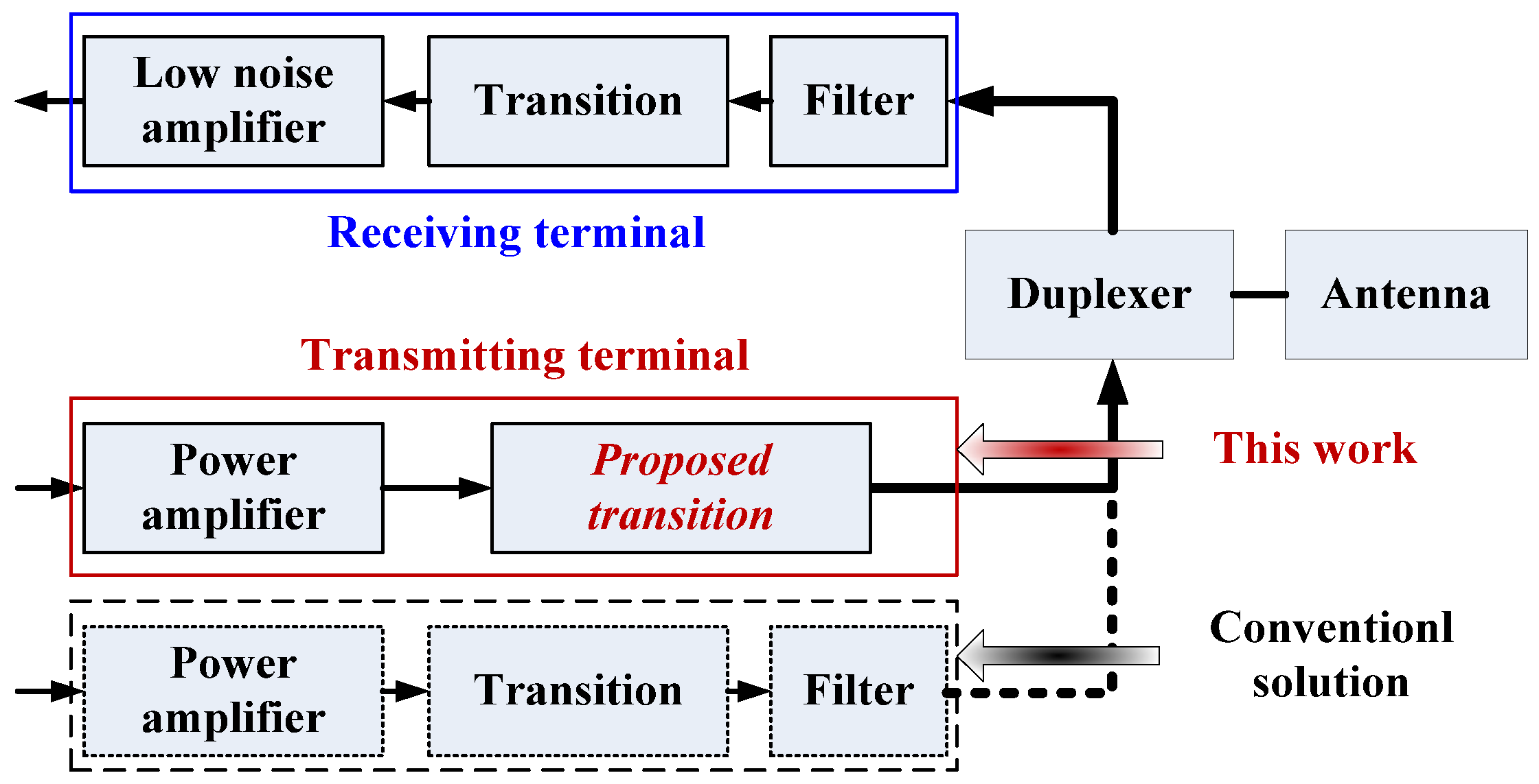
Figure 1. The location of the transition in the ground station.
Electronics 13 04370 g001
Figure 2. Configuration of the microstrip-to-waveguide transition (green color: Rogers Ro 4003(tm) dielectric, silver gray color: cavity shell).
Electronics 13 04370 g002
Figure 3. S parameters for (a) the transition without three patches, (b) the transition without WG2, (c) the transition without three metal probes, and (d) a different m1 (=m2) value, and (e) a different m3 value.
Electronics 13 04370 g003
Figure 4. Fabricated prototype of the microstrip-to-waveguide transition. (a) The ground station, (b) three waveguides with three screws, and (c) the microstrip with three matched patches.
Electronics 13 04370 g004
Figure 5. Measured and simulated S parameters.
Electronics 13 04370 g005
Figure 6. Simulated S parameters for different m3 values.
Electronics 13 04370 g006
Table 1. The parameters for the MTM BPF.
ParameterValue (mm)ParameterValue (mm)
a111.8g23.2
b14a315.8
h17.5b37.9
m13.56h37.8
g13.8g30.67
g41.14l01.5
w10.3l1b0.84
w20.34w40.4
l21.24l41.8
a213.4w00.42
b27.2l1a1.8
h24.5w31.4
m23.56l30.85
m35.18r0.75
w2.3re1.5
Table 2. Performance comparison between current transitions and this work.
Refs.Operating Band (GHz)|S11|
(dB)
Out-of-Band
Suppression
Tunability
[19]11.7–18.7<−10~20 dB @11.5 GHzNo
[20]8–14.5<−10 ~29 dB @7 GHzNo
[21]8.75–12.4<−13NonNo
[23]8.58–12.01<−15~8 dB @8 GHzNo
[26]12–18 <−15 NonNo
[30]33–36.7 <−15 ~20 dB @32 GHzNo
This work14–14.5<−10 ~48 dB @12.55 GHzYes
Disclaimer/Publisher’s Note: The statements, opinions and data contained in all publications are solely those of the individual author(s) and contributor(s) and not of MDPI and/or the editor(s). MDPI and/or the editor(s) disclaim responsibility for any injury to people or property resulting from any ideas, methods, instructions or products referred to in the content.