
An Optimization Method for Design Solutions to Active Reflective Surface Control Systems Based on Axiomatic Design and Multi-Criteria Decision Making

 ,
,
Abstract
:1. Introduction
2. Methods
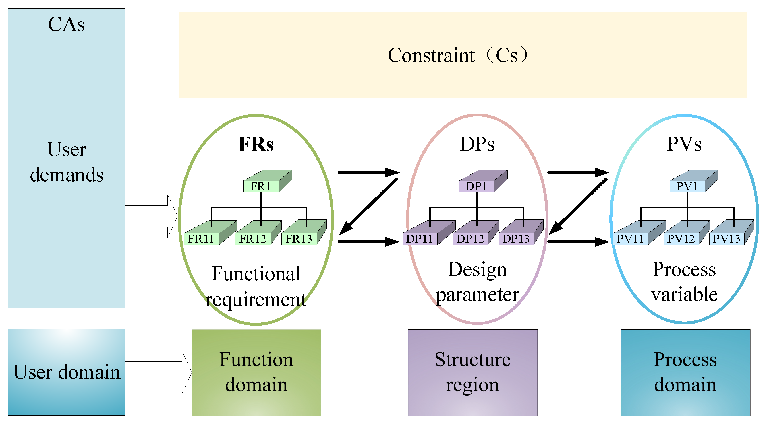
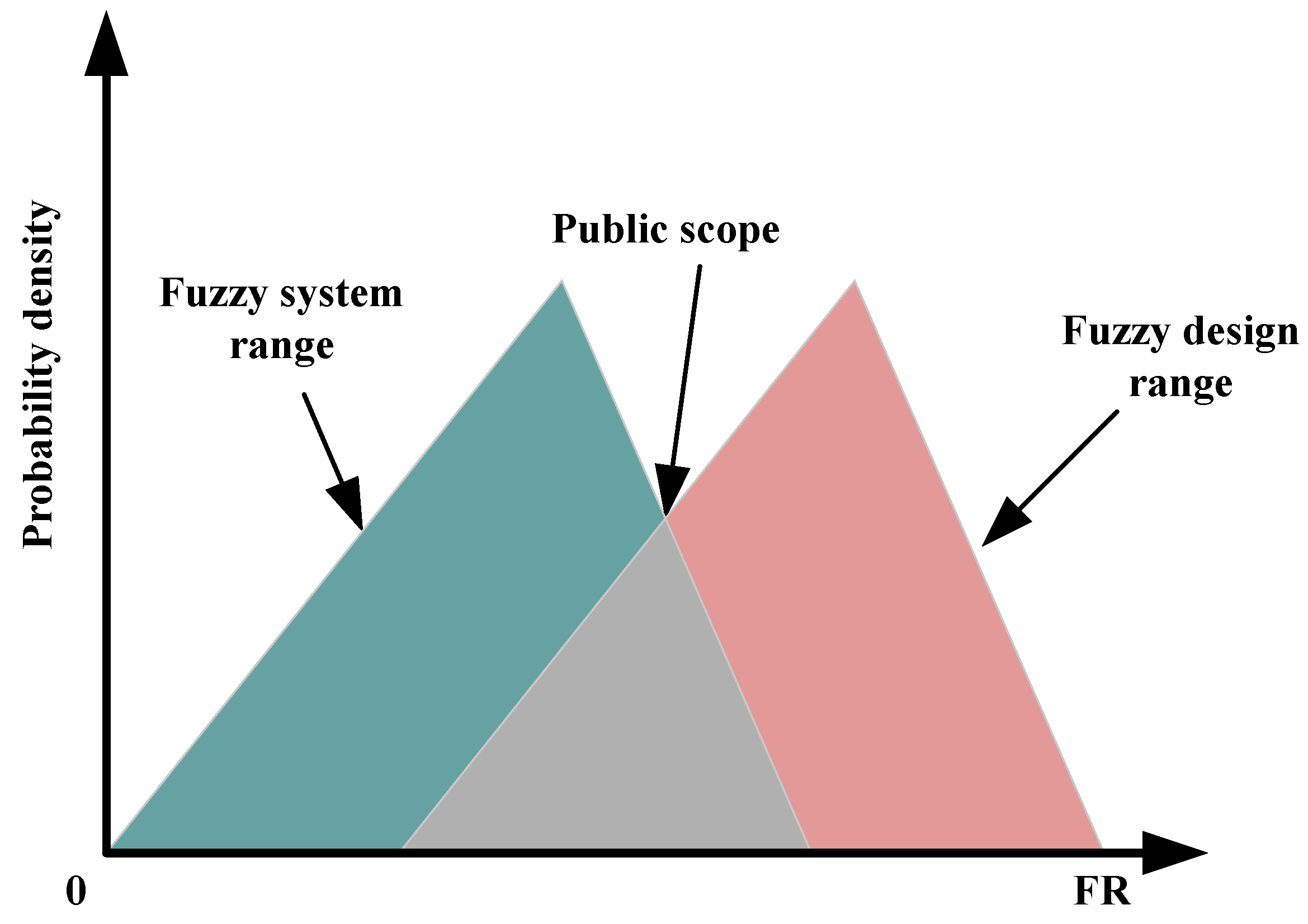
2.1. Principles of Axiomatic Design
2.2. Multi-Criteria Decision Process
3. Axiomatic Design of Systems
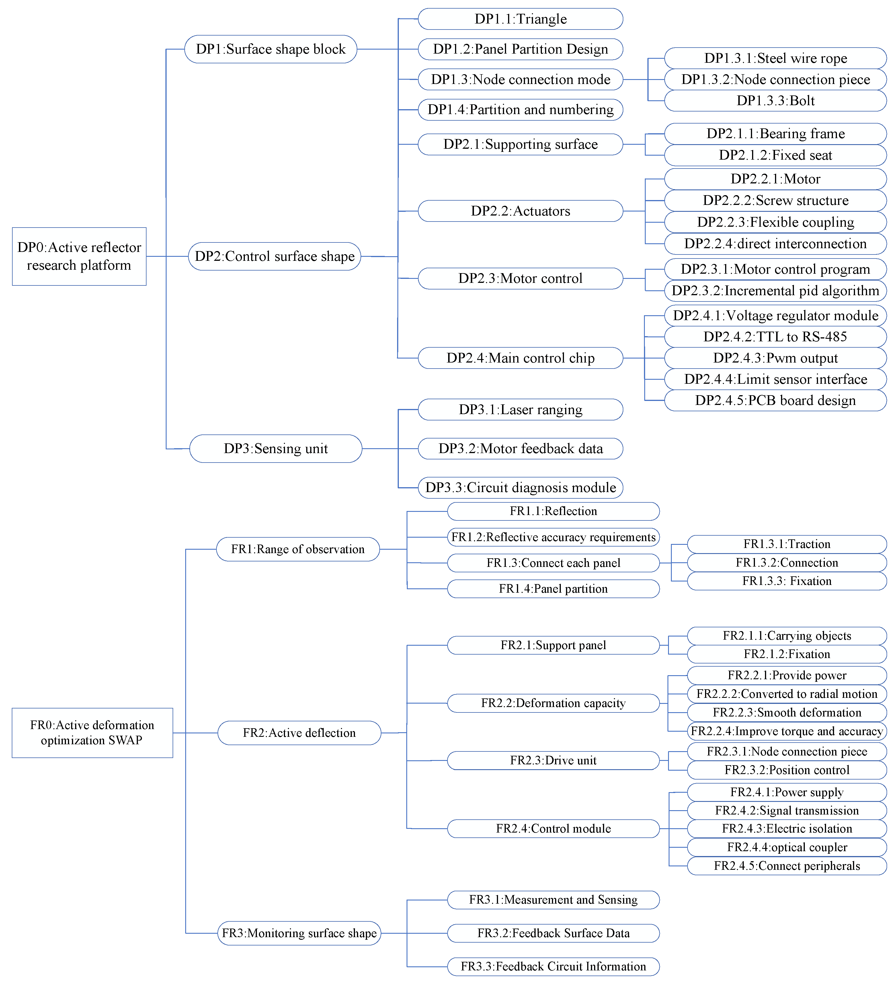
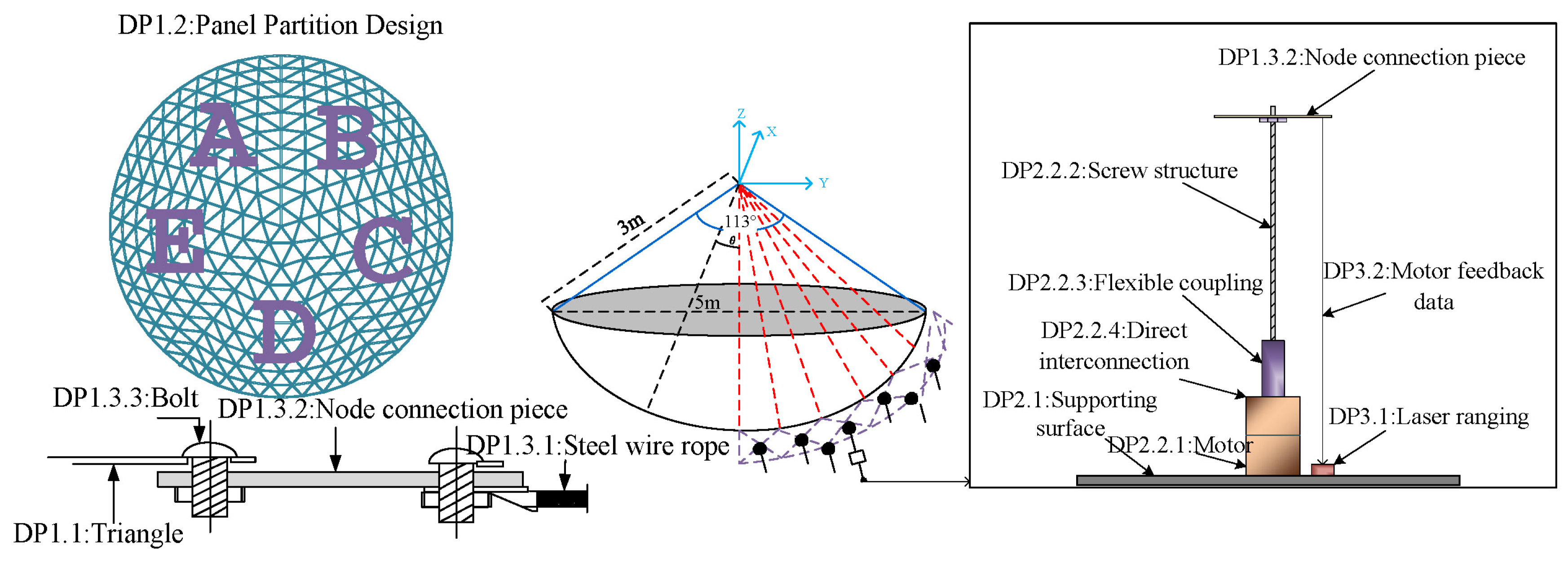
3.1. Structural Hierarchy Design Process
3.1.1. The First Layer of Analysis
3.1.2. The Second Layer of Analysis
3.1.3. The Third Layer of Analysis
3.2. Entire Design Matrix
3.3. Solution
4. Multi-Criteria Decision Making
4.1. Evaluation
4.2. Control Experiments
4.3. Results
5. Conclusions
Author Contributions
Funding
Data Availability Statement
Acknowledgments
Conflicts of Interest
References
- Wang, B.; Cheng, W.; Wang, H.; Zuo, Y. The Experimental Study of Active Surface System for the Large-Aperture, High-Accuracy Radio Telescope. In Proceedings of the 2023 17th Symposium on Piezoelectricity, Acoustic Waves, and Device Applications (SPAWDA), IEEE, Chengdu, China, 10–12 November 2023; pp. 1–4. [Google Scholar]
- Zhang, L. Research on Control Mechanism of FAST Nodes Based on Goal Programming. In Proceedings of the 2022 IEEE International Conference on Electrical Engineering, Big Data and Algorithms (EEBDA), Changchun, China, 25–27 February 2022; pp. 1040–1044. [Google Scholar]
- Wang, Y.; Xiong, Y.; Hao, J.; He, J.; Liu, Y.; He, X. Active Control Model for the “FAST” Reflecting Surface Based on Discrete Methods. Symmetry 2022, 14, 252. [Google Scholar] [CrossRef]
- Zhao, Z.; Xue, X.; Guo, Y. Structural analysis and automatic modeling of ring beam of 500 m aperture radio telescope. Mod. Comput. 2019, 25, 8–13. [Google Scholar]
- Zhang, T.; Guo, Y.; Zhang, Q. The creation of the digital twin model of the FAST reflector unit. Mod. Comput. 2020, 25, 15–21. [Google Scholar]
- Zhang, Q.; Zhao, Y.; Lin, H.; Zhao, Z. Monotone Co-Design Method of Active Reflector Control System Based on Motor Selection. Mach. Build. Autom. 2024, 53, 223–228. [Google Scholar] [CrossRef]
- Lee, K.D.; Suh, N.P.; Oh, J.H. Axiomatic design of machine control system. CIRP Ann. 2001, 50, 109–114. [Google Scholar] [CrossRef]
- Aydoğan, S.; Günay, E.E.; Akay, D.; Kremer, G.E.O. Concept design evaluation by using Z-axiomatic design. Comput. Ind. 2020, 122, 103278. [Google Scholar] [CrossRef]
- Kannan, D.; Govindan, K.; Rajendran, S. Fuzzy axiomatic design approach based green supplier selection: A case study from Singapore. J. Clean. Prod. 2015, 96, 194–208. [Google Scholar] [CrossRef]
- Zhou, H.; Xue, S.; Bao, Z.; Zhang, X.; Chen, Y. Agricultural Micro-Tiller Detachability Research and Multi-Module Design Development. Sustainability 2024, 16, 8594. [Google Scholar] [CrossRef]
- Yang, Y.; Zuo, Q.; Zhang, K.; Li, X.; Yu, W.; Ji, L. Research on Multistage Heterogeneous Information Fusion of Product Design Decision-Making Based on Axiomatic Design. Systems 2024, 12, 222. [Google Scholar] [CrossRef]
- Liu, Q.; Chen, J.; Yang, K.; Liu, D.; He, L.; Qin, Q.; Wang, Y. An integrating spherical fuzzy AHP and axiomatic design approach and its application in human–machine interface design evaluation. Eng. Appl. Artif. Intell. 2023, 125, 106746. [Google Scholar] [CrossRef]
- Saleh, N.; Gaber, M.N.; Eldosoky, M.A.; Soliman, A.M. Vendor evaluation platform for acquisition of medical equipment based on multi-criteria decision-making approach. Sci. Rep. 2023, 13, 12746. [Google Scholar] [CrossRef] [PubMed]
- Lu, H.; Zhao, L.; Wang, X.; Zhao, H.; Wang, J.; Li, B. Comprehensive performance assessment of energy storage systems for various application scenarios based on fuzzy group multi criteria decision making considering risk preferences. J. Energy Storage 2023, 72, 108408. [Google Scholar] [CrossRef]
- Sánchez-Lozano, J.; Fernández-Martínez, M. Near-Earth object hazardous impact: A multi-criteria decision making approach. Sci. Rep. 2016, 6, 37055. [Google Scholar] [CrossRef] [PubMed]
- Come Zebra, E.I.; Windt, H.J.v.d.; Nhambiu, J.O.P.; Golinucci, N.; Gandiglio, M.; Bianco, I.; Faaij, A.P.C. The Integration of Economic, Environmental, and Social Aspects by Developing and Demonstrating an Analytical Framework That Combines Methods and Indicators Using Mavumira Village as a Case Study. Sustainability 2024, 16, 9829. [Google Scholar] [CrossRef]
- Alqahtani, F.M.; Noman, M.A. An Integrated Fuzzy Delphi and Fuzzy AHP Model for Evaluating Factors Affecting Human Errors in Manual Assembly Processes. Systems 2024, 12, 479. [Google Scholar] [CrossRef]
- Kulak, O.; Kahraman, C. Multi-attribute comparison of advanced manufacturing systems using fuzzy vs. crisp axiomatic design approach. Int. J. Prod. Econ. 2005, 95, 415–424. [Google Scholar] [CrossRef]
- Haoqi, W. Research on Model-Based Systems Design Theory and Modeling Methodology. Ph.D. Thesis, Beijing Institute of Technology, Beijing, China, 2018. [Google Scholar]
- Kuo, M.S.; Liang, G.S.; Huang, W.C. Extensions of the multicriteria analysis with pairwise comparison under a fuzzy environment. Int. J. Approx. Reason. 2006, 43, 268–285. [Google Scholar] [CrossRef]
- Lu, M.; Wevers, K. Application of grey relational analysis for evaluating road traffic safety measures: Advanced driver assistance systems against infrastructure redesign. IET Intell. Transp. Syst. 2007, 1, 3–14. [Google Scholar] [CrossRef]
- Chen, M.F.; Tzeng, G.H. Combining grey relation and TOPSIS concepts for selecting an expatriate host country. Math. Comput. Model. 2004, 40, 1473–1490. [Google Scholar] [CrossRef]
- Kritchanchai, D.; Senarak, D.; Supeekit, T.; Chanpuypetch, W. Evaluating Supply Chain Management Models for Third Party Logistics Operated Supply Processing Distribution in Thai Hospitals: An Analytical Hierarchy Fuzzy TOPSIS Approach. Logistics 2024, 8, 116. [Google Scholar] [CrossRef]
- Liu, J.; Zhang, Q.; Xie, M.; Lin, M.; Xu, Z. A blockchain platform selection method with heterogeneous multi-criteria Decision-Making based on hybrid distance measures and an AHP-EWM weight method. Expert Syst. Appl. 2024, 256, 124910. [Google Scholar] [CrossRef]
- Maghsoodi, A.I.; Mosavat, M.; Hafezalkotob, A.; Hafezalkotob, A. Hybrid hierarchical fuzzy group decision-making based on information axioms and BWM: Prototype design selection. Comput. Ind. Eng. 2019, 127, 788–804. [Google Scholar] [CrossRef]
- Kahraman, C.; Cebi, S.; Onar, S.C.; Oztaysi, B. A novel trapezoidal intuitionistic fuzzy information axiom approach: An application to multicriteria landfill site selection. Eng. Appl. Artif. Intell. 2018, 67, 157–172. [Google Scholar] [CrossRef]
- Cebi, S.; Ilbahar, E.; Atasoy, A. A fuzzy information axiom based method to determine the optimal location for a biomass power plant: A case study in Aegean Region of Turkey. Energy 2016, 116, 894–907. [Google Scholar] [CrossRef]
- Carnevalli, J.A.; Miguel, P.A.C.; Calarge, F.A. Axiomatic design application for minimising the difficulties of QFD usage. Int. J. Prod. Econ. 2010, 125, 1–12. [Google Scholar] [CrossRef]


| Criteria | Description |
|---|---|
| A. Filtering criteria | |
| A1. Degrees of freedom | Freedom of motion |
| A2. Reliability | Start–stop performance and life |
| A3. Connection type | Installation location of the actuator |
| A4. Carrying capacity/kg | Maximum load capacity at run time |
| A5. Drive distance/cm | Maximum distance that the actuator can drive |
| B. Evaluation criteria | |
| B1. Maximum speed | Maximum operating speed of the actuator |
| B2. Reproducibility | Ability of the actuator to return to the same position |
| B3. Cost | Purchase and installation costs |
| A6 | A7 | A8 | A9 | A10 | A11 | |
|---|---|---|---|---|---|---|
| Degrees of freedom | Two degrees of freedom | Two degrees of freedom | Two degrees of freedom | Two degrees of freedom | Two degrees of freedom | Two degrees of freedom |
| Drive type | Electricity | Electricity | Electricity | Electricity | Electricity | Electricity |
| Control type | Servo motor | Servo motor | Servo motor | Servo motor | Servo motor | Servo motor |
| Reliability | General | Good | Good | Better | Good | Better |
| Structural complexity | Simpler | General | Complication | Relatively simple | Relatively complicated | General |
| Bearing capacity | 0–9 | 0–20 | 0–11 | 0–13 | 0–15 | 0–17 |
| Drive distance | 0–200 | 0–280 | 0–150 | 0–400 | 0–600 | 0–650 |
| Speed | 0–150 | 0–400 | 0–200 | 0–300 | 0–200 | 0–200 |
| Reproducibility | 0.02 | 0.045 | 0.1 | 0.05 | 0.03 | 0.04 |
| Cost (×1000) | 20.5 | 22.5 | 18.5 | 25 | 35.5 | 32 |
| Alternative | TOPSlS Relative Closeness | TOPSIS Ranking | Entropy-Weighted Score | Entropy Ranking | VIKOR Qi | VIKOR Ranking | TOPSIS and Grey Relational Analysis Integration | Yi + Ranking |
|---|---|---|---|---|---|---|---|---|
| A6 | 0.581588 | 3 | 0.042529 | 4 | 1 | 6 | 0.7235 | 4 |
| A7 | 0.653621 | 2 | 0.04286 | 3 | 0.029449 | 1 | 0.798 | 1 |
| A8 | 0.053011 | 6 | 0.027392 | 6 | 0.70424 | 5 | 0.724 | 3 |
| A9 | 0.715366 | 1 | 0.056303 | 1 | 0.215041 | 2 | 0.677 | 6 |
| A10 | 0.160129 | 5 | 0.032012 | 5 | 0.428575 | 4 | 0.729 | 2 |
| A11 | 0.399471 | 4 | 0.043794 | 2 | 0.428003 | 3 | 0.681 | 5 |
| TOPSIS Analysis | The TOPSIS method computes a relative closeness score for each alternative, ranking them based on proximity to the ideal solution. Alternative A9 exhibits the highest closeness score of 0.715366, securing the top position in the TOPSIS ranking. A7 follows closely with a score of 0.653621, ranked second, while A8 scores the lowest, with a relative closeness value of 0.053011, placing it in the sixth position. These results suggest that A9 and A7 are the most desirable alternatives when considering all criteria collectively under TOPSIS. |
| EWM | The EWM, which assigns weights based on the degree of information entropy, highlights A9 as the top-ranking alternative, with a weighted score of 0.056303, followed by A11 with a score of 0.043794. A8, again, ranks the lowest, with a score of 0.027392, reinforcing its relative inadequacy across the criteria when assessed independently. This outcome reflects the entropy weighting’s emphasis on criteria dispersion, where the most informative criteria receive higher weighting. |
| VIKOR | The VIKOR method, focused on balancing compromise solutions, assigns the lowest Qi score 0.029449 to A7, designating it as the most preferred alternative. A9 ranks second, with Qi = 0.215041, indicating a competitive compromise solution, while A6 records the highest Qi score of 1, positioning it as the least desirable under this approach. VIKOR’s results suggest that A7 provides the most balanced solution when weighing ideal and anti-ideal distances. |
| TOPSIS-GRA | The integrated TOPSIS-GRA approach further corroborates the results, with A7 achieving the highest composite score of 0.798, followed closely by A10 at 0.729. A9, which ranked first in the standalone TOPSIS method, shows a relative decline, obtaining the lowest score of 0.677 in this integration, ranking sixth. This integrated approach offers a nuanced view by combining the strengths of TOPSIS and GRA, allowing for a more robust assessment by accounting for both similarity to the ideal solution and relational closeness among alternatives. |
| A6 | A7 | A8 | A9 | A10 | A11 | |
|---|---|---|---|---|---|---|
| - | 0.322 | - | 3.322 | 0.322 | 3.322 | |
| 0.7 | 1.7 | - | 1.7 | 4.7 | 1.7 | |
| 3.32 | 4.39 | 3.58 | 3.81 | 4.0 | 4.17 | |
| 7.64 | 8.46 | 7.23 | 8.64 | 8.9 | 8.68 | |
| 7.23 | 8.64 | 7.64 | 8.23 | 7.64 | 7.64 | |
| 4.64 | 3.46 | 2.32 | 3.32 | 4.07 | 3.64 | |
| 0 | 0 | 0 | 0 | 0 | 0 | |
| Information content | - | 26.96 | - | 29.022 | 29.632 | 29.152 |
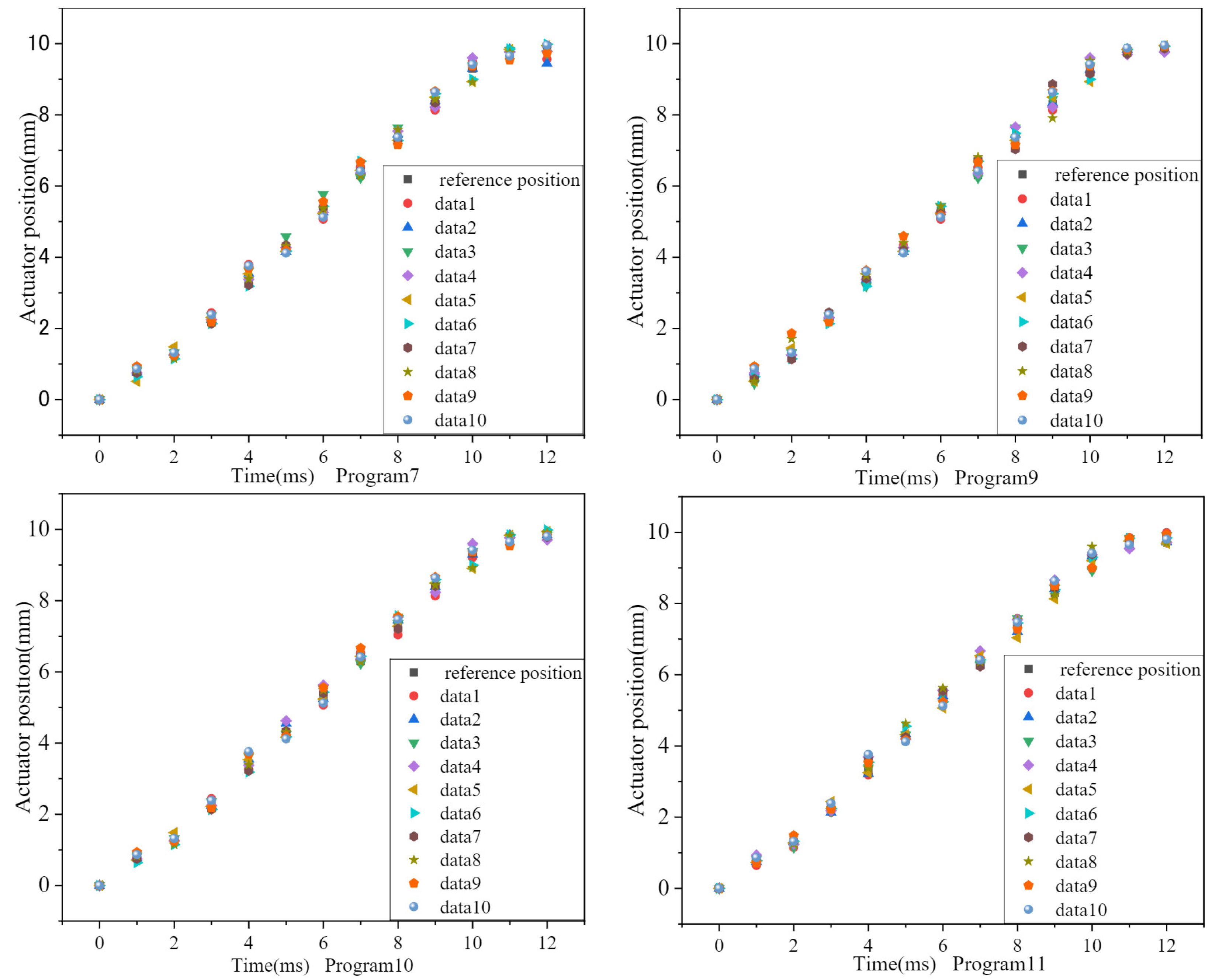
| Program | A7 | A9 | A10 | A11 |
|---|---|---|---|---|
| Average error/mm | 0.213 | 0.296 | 0.312 | 0.358 |
Disclaimer/Publisher’s Note: The statements, opinions and data contained in all publications are solely those of the individual author(s) and contributor(s) and not of MDPI and/or the editor(s). MDPI and/or the editor(s) disclaim responsibility for any injury to people or property resulting from any ideas, methods, instructions or products referred to in the content. |
© 2024 by the authors. Licensee MDPI, Basel, Switzerland. This article is an open access article distributed under the terms and conditions of the Creative Commons Attribution (CC BY) license (https://creativecommons.org/licenses/by/4.0/).
Share and Cite
Zhang, Q.; Zhang, X.; Zhao, Q.; Zhao, S.; Zhao, Y.; Guo, Y.; Zhao, Z. An Optimization Method for Design Solutions to Active Reflective Surface Control Systems Based on Axiomatic Design and Multi-Criteria Decision Making. Electronics 2024, 13, 4655. https://doi.org/10.3390/electronics13234655
Zhang Q, Zhang X, Zhao Q, Zhao S, Zhao Y, Guo Y, Zhao Z. An Optimization Method for Design Solutions to Active Reflective Surface Control Systems Based on Axiomatic Design and Multi-Criteria Decision Making. Electronics. 2024; 13(23):4655. https://doi.org/10.3390/electronics13234655
Chicago/Turabian StyleZhang, Qinghai, Xiaoqian Zhang, Qingjian Zhao, Shuang Zhao, Yanan Zhao, Yang Guo, and Zhengxu Zhao. 2024. "An Optimization Method for Design Solutions to Active Reflective Surface Control Systems Based on Axiomatic Design and Multi-Criteria Decision Making" Electronics 13, no. 23: 4655. https://doi.org/10.3390/electronics13234655
APA StyleZhang, Q., Zhang, X., Zhao, Q., Zhao, S., Zhao, Y., Guo, Y., & Zhao, Z. (2024). An Optimization Method for Design Solutions to Active Reflective Surface Control Systems Based on Axiomatic Design and Multi-Criteria Decision Making. Electronics, 13(23), 4655. https://doi.org/10.3390/electronics13234655