Abstract
To solve the online path planning of multi-robots in dynamic environments, a novel secondary immune responses-based immune path planning algorithm (SIRIPPA) is presented. The algorithm comprises two immune stages. In the primary immune stage, the antibodies are mainly designed for obstacle avoidance and a primary immune kinetic model is designed in terms of the different impacts of obstacles on robot behaviors. The primary immune antibodies and their concentration values are mainly taken as the prior knowledge to accelerate the secondary immune response. In the secondary immune stage, aiming at the same obstacle antigens, which invade once more, the immune system quickly produces many behavior antibodies. Combining the primary immune results and secondary immune response results, the path planning performance of multi-robots is improved. The simulation experiment indicates that, in static environment tests, compared to corresponding immune planning algorithms, the SIRIPPA exhibits an average reduction of 6.22% in the global path length, a decrease of 23.00% in the average smoothness, and an average energy consumption reduction of 27.55%; the algorithm exhibits a better performance for path planning. The simulation test in a dynamic environment shows the good flexibility and stability of the SIRIPPA. Additionally, the experimental results in a real environment further support the validity of the SIRIPPA.
1. Introduction
As one of the most important tasks for autonomous mobile robot navigation, path planning refers to searching for the optimal and collision-free path from the starting point to the goal based on the optimization criteria (e.g., minimal working cost or shortest route) [1]. According to the environmental acquisition mode and the size of the acquired environment, path planning can be divided into global path planning and local path planning. Global path planning methods include the genetic algorithm (GA) [2] and ant colony algorithm (ACA) [3]. The genetic algorithm (GA) is an optimization search algorithm that simulates the evolutionary process of natural organisms. Witch has a wide range of applications in combinatorial optimization, function optimization, automatic control, production scheduling, and path planning processes [4]. The GA possesses excellent global and distributed search capabilities. However, when addressing path planning problems, the algorithm tends to have a high computational load, impacting its real-time performance. The ACA is characterized by its global optimization capability, positive feedback, and high robustness. However, its search efficiency is low, and the search capability is limited to the division of grids. The commonly used algorithms for local path planning include the artificial potential field (APF) method [5], fuzzy algorithm [6], neural network algorithm [7], and rapidly exploring random tree (RRT) algorithm [8]. The APF method solves path planning by constructing the attractive and repulsive potential fields and is characterized by a simple model and its low calculation requirements. However, it can also easily become trapped in local minima. The fuzzy planning algorithm overcomes the issue of becoming trapped in local minima. However, the acquisition of fuzzy rules and the selection of the fuzzy set universe are influenced by human factors. As for the neural network algorithm, it is difficult to acquire complete learning samples, especially the samples in dynamic environments. The significant characteristic of the RRT (rapidly exploring random tree) algorithm and its variants lies in the random exploration of space, particularly in path planning for high-dimensional spaces. However, due to the inherent randomness of the RRT algorithm, the computational efficiency of the algorithm is relatively low, impacting its real-time applicability in complex environments.
In recent years, in order to continuously enhance the performance of path planning algorithms, particularly in terms of their search capabilities and convergence speeds in complex dynamic environments, many researchers have undertaken a series of design improvements. Kairong Li et al. [9] improved the method for establishing the initial population, crossover operators, etc., and proposed an improved multi-objective genetic algorithm (IMGA), which improved the feasibility of the initial path and the shortcomings of traditional genetic algorithms, such as slow convergence speed and susceptibility to local traps, effectively shortening the path length. However, there is still significant randomness in individual selections and the stability of the algorithm is low. Kangjing Shi et al. [10] conducted genetic operations, including crossovers and mutations, on the initial path obtained by the ant colony algorithm (ACA) to achieve an enhanced path planning solution. They introduced a path planning algorithm that integrated the GA and ACA (GA-ACO), resulting in the improved efficiency and accuracy of path planning. Nevertheless, since the turning angles of robots are still constrained by the number of distance-detection sensors, further enhancements are required for the planning performance in terms of the length and smoothness. AD Sabiha et al. [11] integrated and optimized the GA and PSO, applied the TLBO to determine the optimal online path, and minimized the path smoothness. They proposed a new GA-PSO path planning algorithm, which improved the planning efficiency; however, there is still a need for the improvement of local planning performances in dynamic, unpredictable environments. Path planning in complex environments is a hotspot and difficulty research area in robotics studies. Although considerable planning methods are provided for online dynamic planning, they still remain in the simulation phase.
Inspired by the biological immune system (BIS), the artificial immune system (AIS) has been an active area of research in robotics for its strong adaptability, diversity, learning, recognition, and memory capabilities. [12]. The secondary immune response is a crucial feature of the biological immune system. Its advantage lies in its rapid and robust immune reaction against pathogens previously encountered, leading to more effective resistance against invasions. If the mechanism of the secondary immune response is incorporated into artificial immune-based path planning algorithms, this advantage translates into a faster search ability and the enhanced adaptability of the algorithm to complex, dynamic environments. Therefore, in order to solve online path planning in dynamic environments, a new secondary immune response-based immune path planning algorithm (SIRIPPA) is proposed in this paper. Its planning performance is initially tested through simulations in both static and dynamic environments. Subsequently, an experiment is conducted to further validate its efficacy.
2. Path Planning Model Based on the Immune Network Theory
2.1. Idiotypic Immune Network Hypothesis
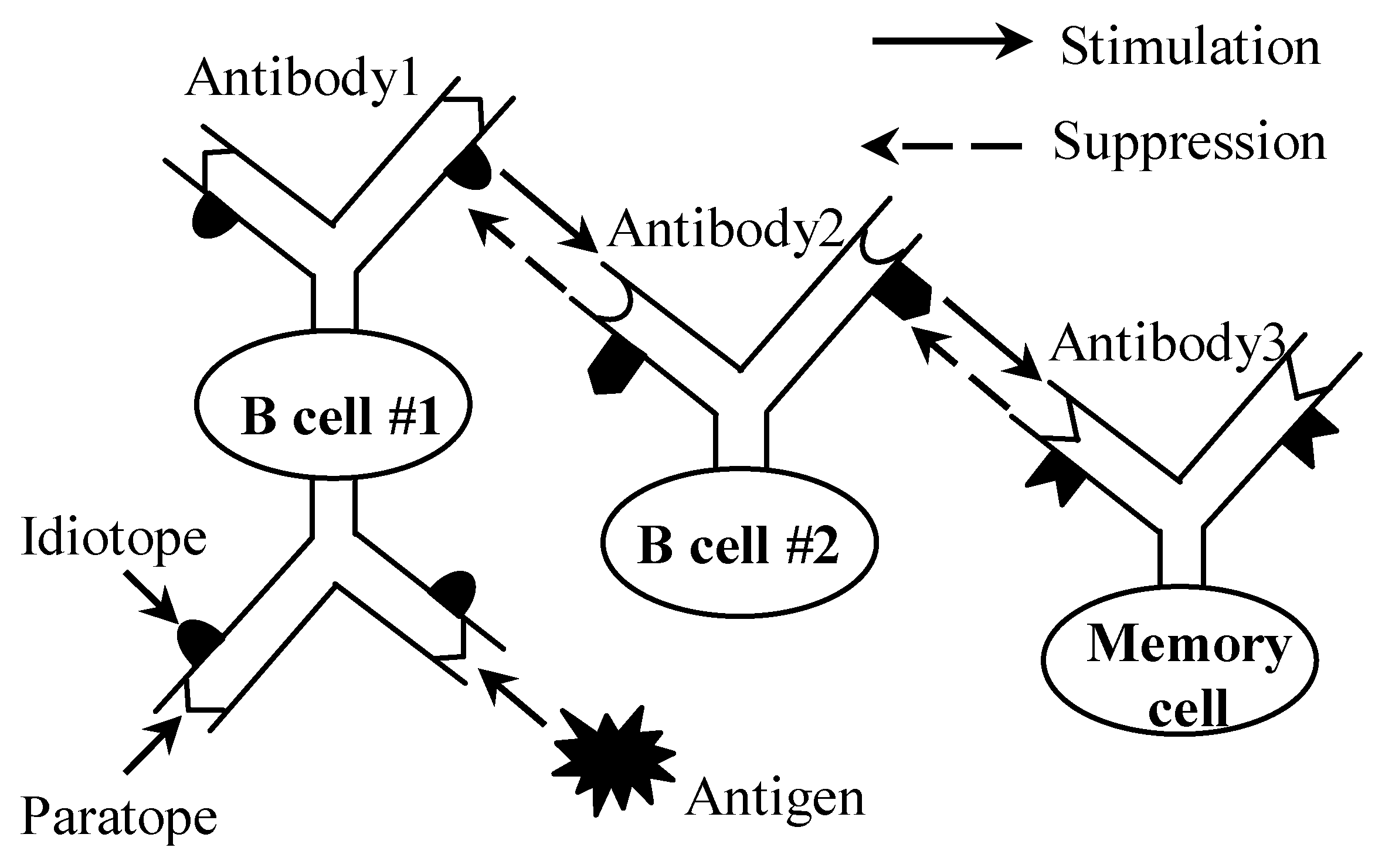
The biological immune system is a highly evolved, complex, and adaptable system capable of identifying and resisting antigenic foreign bodies, such as bacteria and viruses, while maintaining stability in an in vivo environment. The idiotypic network hypothesis [13] developed by Jerne in 1972 is one of the important immune theories. The idea of the hypothesis is schematically shown in Figure 1. The biological immune network involves a series of processes related to self-recognition and the elimination of differences [14]. When an antigen invades, the B cell whose paratope can identify the antigen is activated. Most of the activated B cells differentiate and produce antibodies to clear the antigen, while the others differentiate into memory cells. Through the identification of paratopes and idiotopes among multi-antibodies, a complex immune network is constructed to effectively cope with the invasion of foreign antigens.
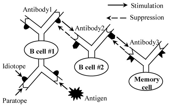
Figure 1.
Biological immune network.
2.2. Descriptions of Immune Planning Model
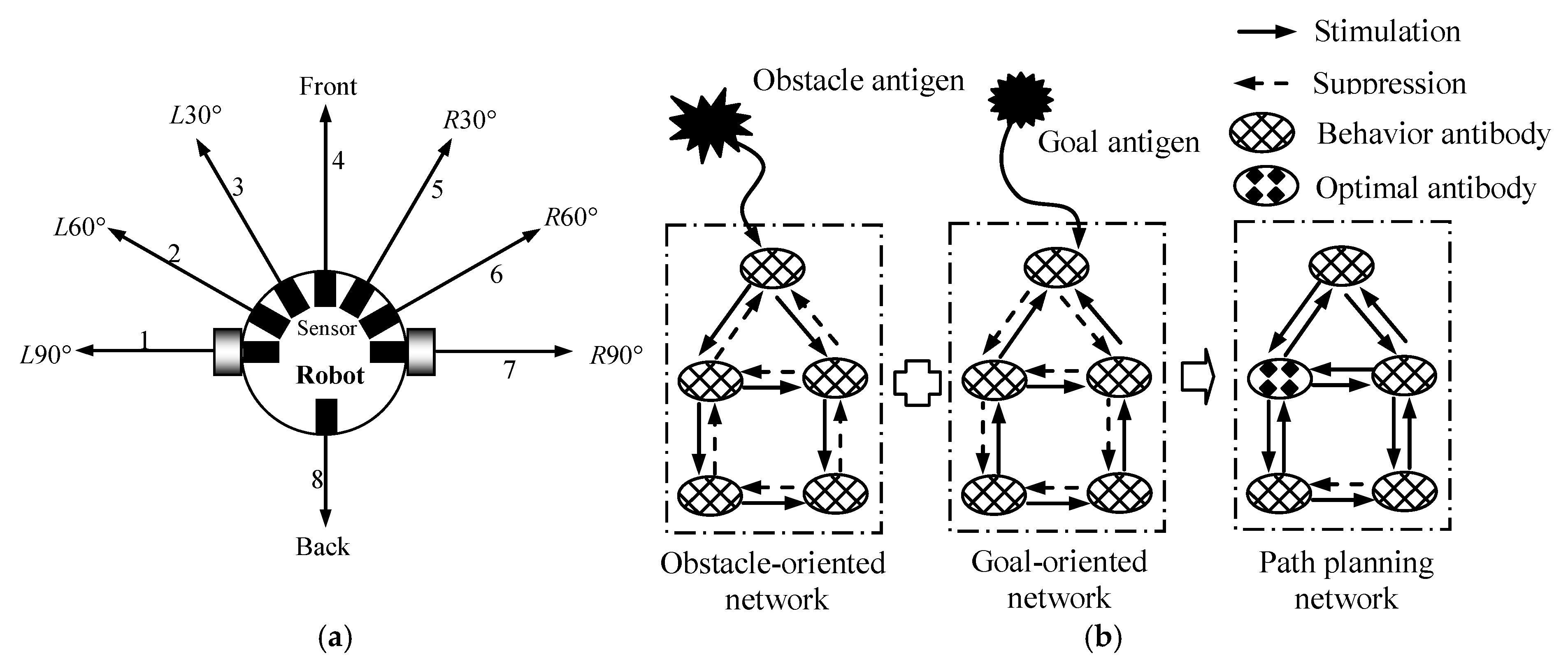
To solve the path planning problem in dynamic environments, inspired by Jerne’s idiotopic network hypothesis, an immune path planning model was designed, as shown in Figure 2 in this paper. The environmental information was chosen as the antigen and the robot behaviors were selected as the antibodies. In the artificial immune system, an omni-directional mobile robot (see Figure 2a) was selected as an immune agent. It was equipped symmetrically, but unevenly, with eight distance-detection sensors around it. Eight detection directions, D1 (i.e., L90°, L60°, L30°, front, R30°, R60°, R90°, and back) corresponded to eight movement directions, M1, of the robot, namely M1 = D1. Figure 2b shows the construction principle of the immune planning network. Because of the complexity and uncertainty of the environment surrounding the robots, it was difficult for the multi-robots to cope with the environmental information effectively using a single immune network. To address the balance between the influence of obstacles and the goal, a mutual-coupled immune network was employed, consisting of an obstacle-oriented network and a goal-oriented network. In the obstacle-oriented network, the obstacle information (i.e., the distance between an obstacle and a robot) was defined as the obstacle antigen. In the goal-oriented network, the goal information (i.e., the direction of an obstacle relative to a robot) was defined as the goal antigen. Once a mobile robot detected an obstacle antigen and a goal antigen, the obstacle-oriented and goal-oriented networks were produced. During the immune path planning phase, a series of optimal antibodies (i.e., optimal robot behaviors) were selected for the multi-robots to complete their navigations through the stimulation and suppression among antigens and antibodies in the planning network.
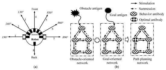
Figure 2.
Immune path planning model. (a) Immune agent; (b) principle of the immune path planning network.
Based on the genetic algorithm, the IMGA [9], GA-ACO [10], and GA-PSO [11] could complete their path planning activities by selecting optimal antibodies. However, because the number of antibodies presented in the three algorithms above was limited to the number of robot distance sensors and the included angle between the two adjacent sensors was relatively large, the turning angle for obstacle avoidance was usually larger, especially in the environments with many obstacles. A large turning angle easily resulted in the longer length and reduced smoothness of the planned path. In addition, some antibodies with the same concentrations were easily produced based on a single immune concentration calculation and the robot approached its goal by zigzagging because of the random selection of antibodies. The stronger adaptive and self-adjusting functions of the BIS had a great relationship with the action of the secondary immune response. To solve the path planning in dynamic environments and further improve the planning performance, based on the biological secondary immune response, a secondary immune planning model was designed in this paper to subdivide the turning angles of the robots, which was helpful in shortening the length and improving the smoothness of the planned path.
3. Secondary Immune Path Planning
3.1. Secondary Immune Response
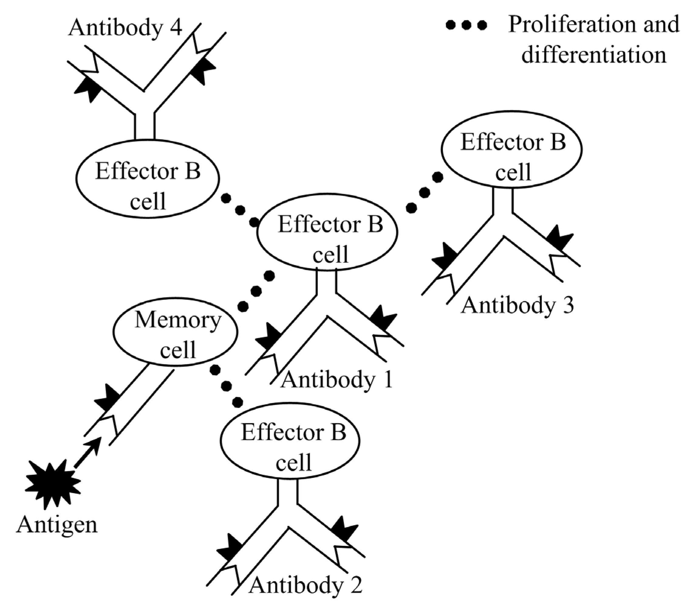
In a biological immune system, memory cells generated by the primary immune response can exist for long time. When the same antigen invades the body again, the memory cells are quickly activated, proliferated, and differentiated to produce effector B cells. Then, the effector B cells produce antibodies to clear the antigen in time. This phenomenon in the BIS is called the second immune response. Figure 3 shows the principle of the biological secondary immune response [15]. The secondary immune response plays a crucial role in maintaining the dynamic immune balance of the BIS owing to the vast number of antibodies and the faster response speed. In view of this, the introduction of the secondary immune response was implemented in the path planning process to enhance the planning performance.
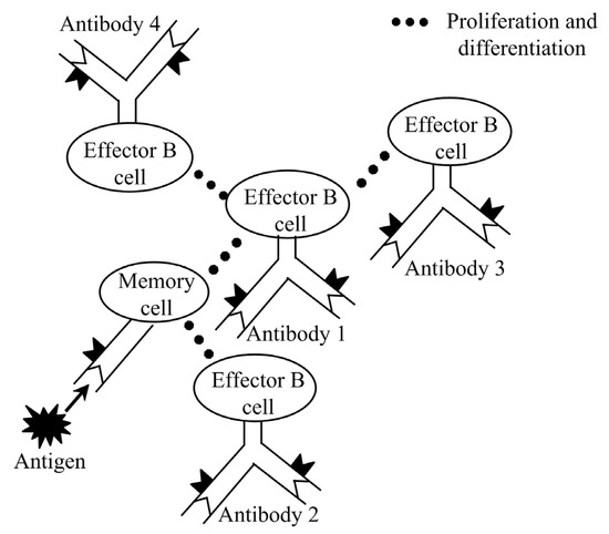
Figure 3.
Biological secondary immune response.
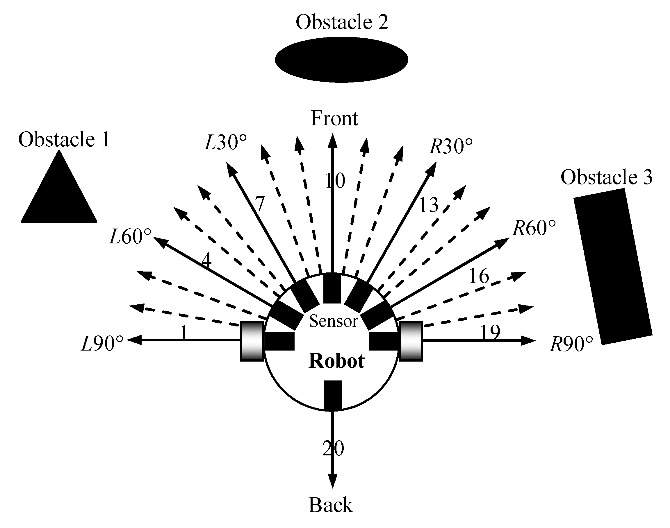
Due to the paramount importance of obstacle avoidance in the path planning process for mobile robots, we exclusively addressed the influences of obstacles on robots during the primary immune stage. In this stage, we specifically regarded the obstacle information in the direction of M1 as the memory B cells. In the secondary immune stage, when the same antigen invaded the body again, the memory B cells underwent rapid proliferation and differentiation, and more movement directions M2 (i.e., L90°, L80°, L70°, L60°, L50°, L40°, L30°, L20°, L10°, front, R10°, R20°, R30°, R40°, R50°, R60°, R70°, R80°, R90°, and back) were produced for the mobile robot, as shown in Figure 4.
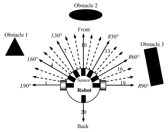
Figure 4.
The proliferation and differentiation of memory B cells.
3.2. Definitions of Antigen and Antibody
Definition 1.
Let the obstacle information detected by a robot be the primary immune antigen, e′.
where e′ is coded by a binary value. is the detection result regarding obstacles in direction l. ∀ l ∈ {1, 2, …, 8}, , where the elements “0” and “1” represent “no obstacle” and “obstacle” in direction l, respectively. The string length, 8, of e′ depends on the number of distance-detection sensors.
Definition 2.
Let the information for the obstacle and goal be the secondary immune antigen, e″.
where is the obstacle antigen coded by the binary value, which has a string length of 20. It is related to the moving directions of a mobile robot in the secondary immune stage. ∀ l ∈ {1, 2, …, 20}, . is the goal antigen and is also coded by the binary value. ∀ l ∈ {1, 2, …, 20}, , where the elements “0” and “1” denote “no goal” and “goal” in direction l, respectively.
Definition 3.
The primary immune antibody is designed according to the primary immune antigen, e′, and consists of the paratope and idiotope. The preconditions of the obstacle and robot behavior are taken as the paratope, and the interaction antibody, stimulation value, and suppression value are taken as the idiotope.
Figure 5 shows the model of primary immune antibody i ().

Figure 5.
Definition of antibody i.
Antibody can be formulated as:
where is the paratope of primary immune antibody i. The term denotes the precondition of the obstacle, and its string length corresponds to the number of distance-detection sensors. ∀ l ∈ {1, 2, …, 8}, , where the elements “0” and “1” still denote “no obstacle” and “obstacle”, respectively. The element “#” denotes that the condition can be taken as either “0” or “1”. denotes the robot’s behavior (i.e., movement direction) and . The detailed definitions of the paratope, , are shown in Table 1. is the idiotope of ; IAj denotes the interaction with antibody . represents the stimulation value of on and mij represents the suppression value of on .

Table 1.
Definitions regarding the paratopes of primary immune antibodies.
Definition 4.
The secondary immune antibody is designed according to the secondary immune antigen e″ and still consists of the paratope and idiotope.
In the secondary immune stage, because the turning angles of the robots were subdivided based on the proliferation and differentiation of the memory cells, more moving directions were produced. Thus, the number of secondary immune antibodies was expanded. The secondary immune antibody, i (), can be formulated as:
The detailed definitions of the paratope, , are shown in Table 2. ∀ l ∈ {1, 2, …, 20}, , where the elements “0”, “1”, and “#” are defined as the same definitions in . is the robot’s behavior (i.e., movement direction). and are the stimulation values of and on , respectively.

Table 2.
Definitions regarding the paratopes of secondary immune antibodies.
Thus, the primary immune antibody set, , and the secondary immune antibody set, , were obtained.
3.3. Antibody Selection of Robots Based on the Immune Concentration
Although two types of antibody sets, A′ and A″, were designed and presented in Section 3.2, only activated antibodies were likely to be selected to execute the path planning stage. In the primary immune stage, aiming at the obstacle antigen, the activated primary antibody group, Ap, was obtained through operator Tp.
where the symbols “¯” and “∨” denote the “NOT” and “AND” operators, respectively. N is the number of activated primary antibodies and N ≤ 8. ∀ ; if , then .
On the basis of Farmer’s immune kinetic model, the concentration, , of the activated primary antibody group, Ap, at time, t, is obtained through operator Ψp.
where α1 and α2 are the stimulation and suppression coefficients among the primary immune antibodies, respectively. In the braces, the last equational term was the primary immune kinetic model for the calculation of concentration Cp.
The stimulation value, mji, of on is described as:
where the symbol “⊕” denotes the “exclusive-or” operator.
∀; if , then .∀, and if , then .
The suppression value, mij, of on is described as:
If or , then .
In the secondary immune stage, when the same obstacle antigen invaded again, some of the secondary immune antibodies in were activated through operator Ts to form an activated secondary immune antibody group, As.
where D is the number of activated secondary immune antibodies and D ≤ 20. ; if , then .
To improve the quality of the activated secondary immune antibodies and accelerate the planning speed, the concentration, , of the activated primary immune antibodies was taken as a priori knowledge to initialize the concentration, , of .
The initial concentration, , of D activated secondary immune antibodies is described as:
where fix(·) is the round function and returns the integer part of a number.
The selection of the activated secondary immune antibodies for path planning depended on the final concentration, Cs, of the activated secondary immune antibodies, As. ∀; the concentration of antibody i at time t is calculated according to the secondary immune kinetic model (i.e., Equations (16)–(18)):
In Equation (16), Si(t) is the stimulation level at time t. is the normalized concentration of antibody at time t − 1. In Equation (17), β1 is the stimulation coefficient of on . β2 is the stimulation coefficient of on . The consumption factor, k, denotes the natural death of the antibody, .
The stimulation value, , of on is described as:
∀; if , then .
The stimulation value, , of on is described as:
; if , then .
The whole acquisition process regarding concentration of the activated secondary immune antibodies As can be described through operator Ψs as:
Finally, the optimal antibody, a*, was selected through operator Γ in As.
3.4. Flow of the Secondary Immune Planning Algorithm
To further improve the immune planning performance, inspired by the secondary immune response, a secondary immune planning model was designed and a new secondary immune responses-based immune path planning algorithm was put forward. The algorithmic steps presented in Algorithm 1 illustrate the key stages of the SIRIPPA path planning algorithm.
| Algorithm 1. SIRIPPA Algorithm |
| Begin: Initialization: stimulation coefficient α1, suppression coefficient α2, stimulation coefficient β1, suppression coefficient β2, consumption factor k, etc. Set the primary immune antibody set, A′, and secondary immune antibody set, A″. While (robots that have not achieved their goals) Code the primary immune antigen, e′, and secondary immune antigen, e″, according to the environmental information. Primary immune stage: Secondary immune stage: Select the optimal antibody: end while end |
4. Simulation Tests of the SIRIPPA
To test and verify the validity and stability of the proposed SIRIPPA, selected simulations were performed using MATLAB 8.2 on an Intel Core 11th 2.4 GHz computer (Intel Co., Santa Clara, CA, USA) with 8 GB of RAM. In the SIRIPPA, α1 = 0.2, α2 = 0.04, β1 = 0.5, β2 = 0.5, and k = 0.5.
4.1. Simulation Tests in Static Environments
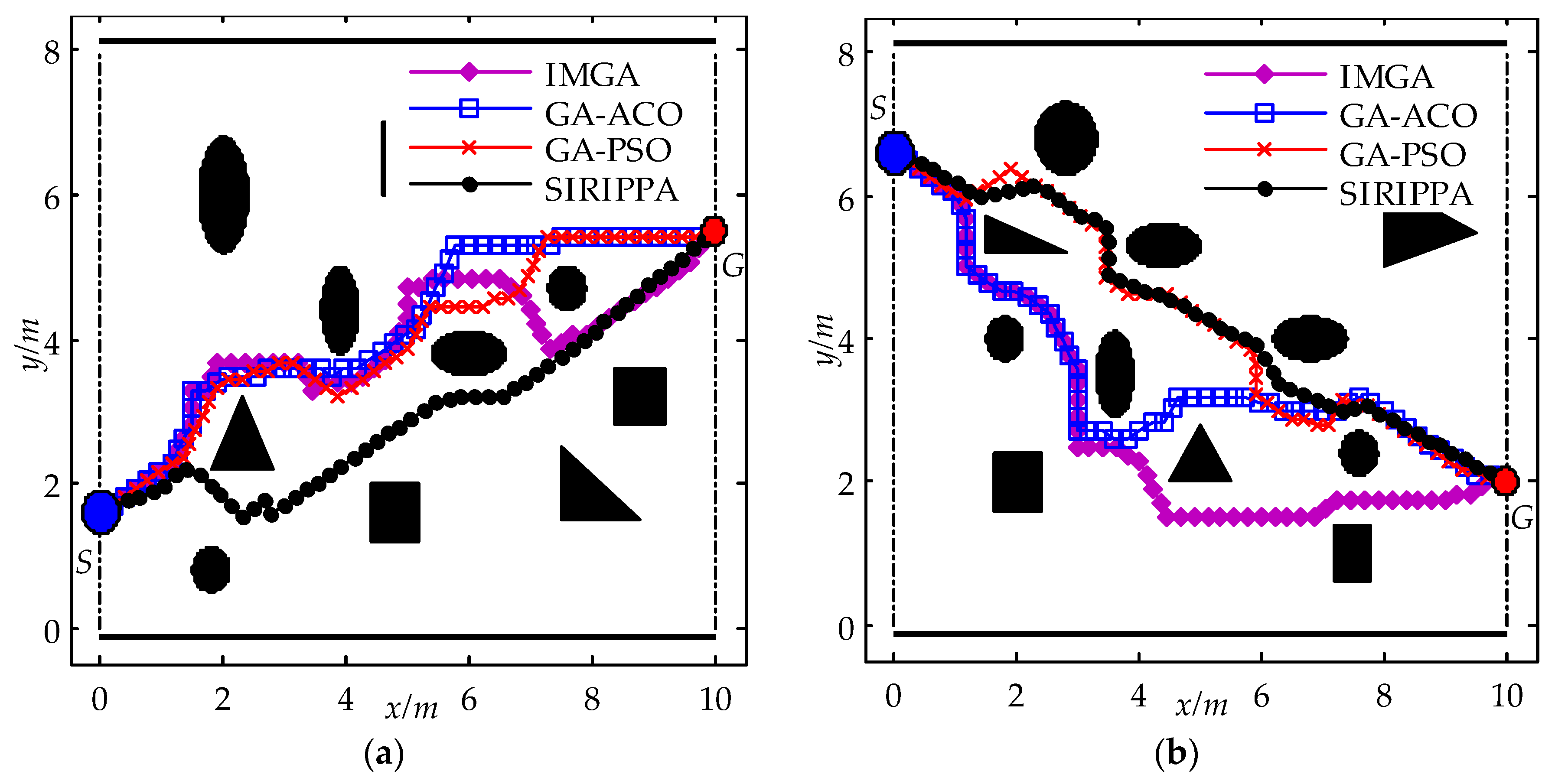
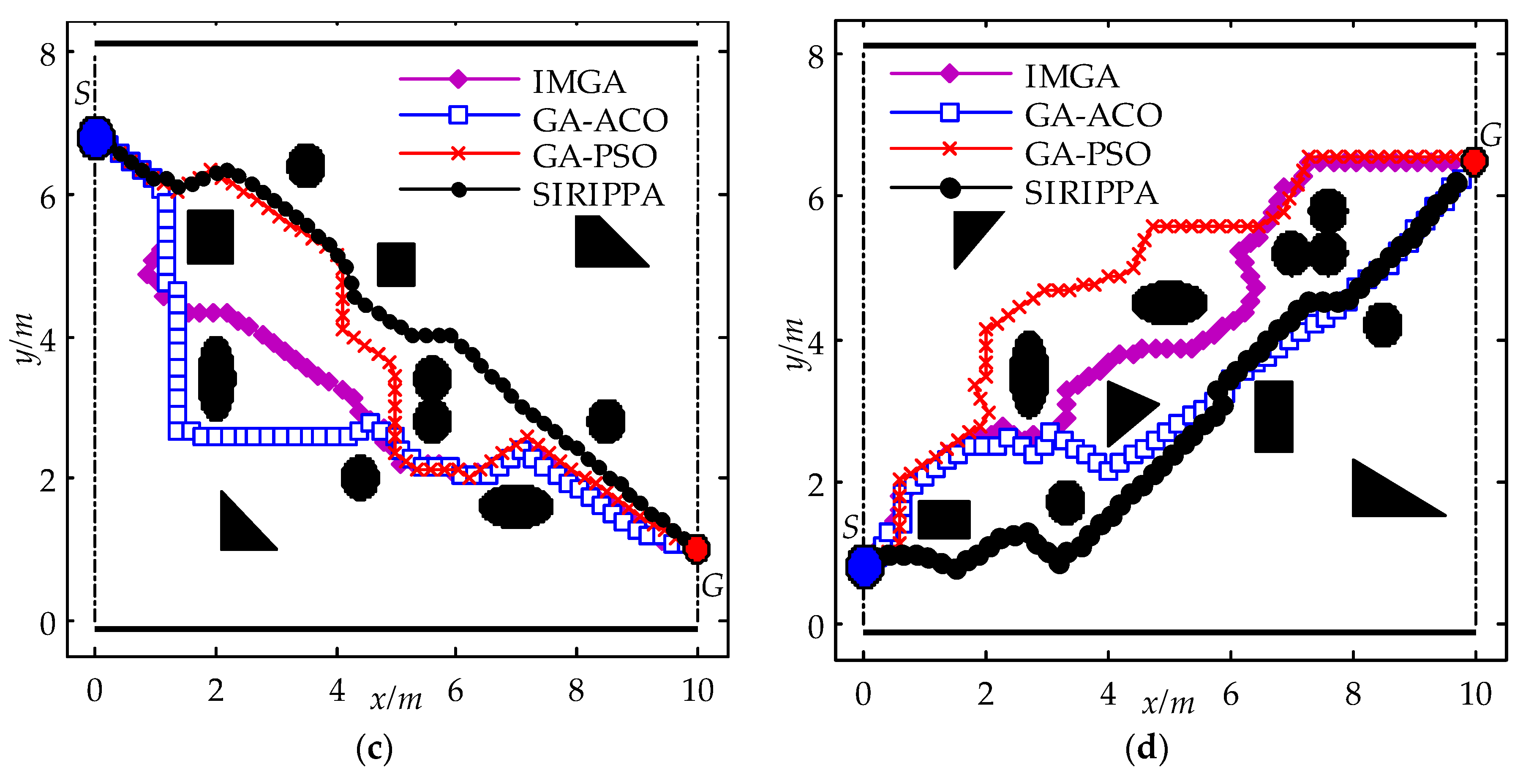
To verify the path planning performance of the SIRIPPA and considering the four different static environments, shown in Figure 6, selected simulation tests were performed firstly, and the planning results of the SIRIPPA were compared with those of the IMGA, GA-ACO, and GA-PSO. All the parameter values of the IMGA, GA-ACO, and GA-PSO were from the relevant literature. Figure 6 shows the planning results for the four immune algorithms.
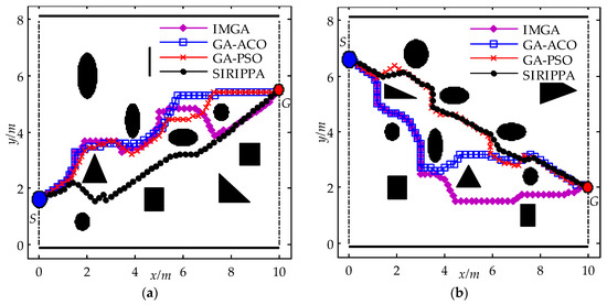
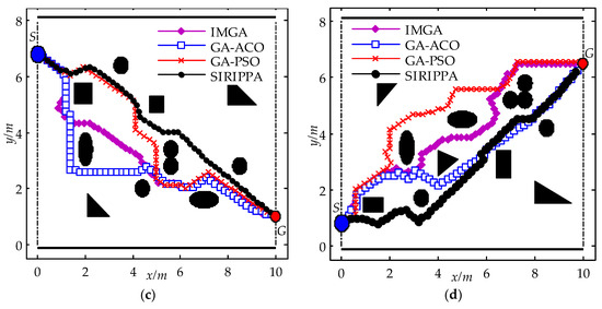
Figure 6.
Path planning results for four immune algorithms in static environments. (a) Environment I; (b) environment II; (c) environment III; (d) environment IV.
In environment I, the obstacles were distributed sparsely around the line between S and G. From Figure 6a, it can be observed that the paths planned by the IMGA, GA-ACO, and GA-PSO appear to be the same. In the SIRIPPA, the turning angles of the robots were effectively subdivided based on the secondary immune response, and the secondary immune planning model enhanced the rationality of the antibody selection. As a result, the robot could navigate around the obstacles with smaller turning angles and approach the goal more rapidly. Comparing the path of the SIRIPPA with the paths of other immune algorithms, it can be observed that the path length of the SIRIPPA is shorter than the other paths. The reduced number of zigzags in the path of the SIRIPPA indicates greater path smoothness. In environment II (Figure 6b), the obstacles are densely distributed around the line between S and G. Due to the limitation of the number of antibodies, both the IMGA and GA-ACO reached the goal, G, after several turns, revealing their limited planning capabilities. In the GA-PSO, the addition of antibodies and the provision of more robot behaviors contributed to greater smoothness compared to the IMGA and GA-ACO. However, because the functions of the added antibodies in the GA-PSO were similar, the competition among these similar antibodies restricted further improvements in the planning performance. In the SIRIPPA, a large number of antibodies were not only provided, but also consistently matched the secondary immune planning model. Additionally, there was no function conflict among the different antibodies, effectively enhancing the planning performance of the SIRIPPA. The path planned by the SIRIPPA was obviously better than that of the GA-PSO. The planning results of the SIRIPPA in environments III and IV (Figure 6c,d) also show its better planning performance.
Table 3 provides detailed performance comparisons in terms of the path length, smoothness, and energy consumption, e, among the four immune planning algorithms. e relates to the length, l, and the smoothness, ϑ, of the planned path:
where L is the linear distance between the starting point, S, and goal, G. θ is the angle between the x-axis and the direction from S to G. The parameter l indeed represents the current displacement or movement distance of the mobile robot, and ϑ denotes the angle between the robot’s direction and the x-axis.

Table 3.
Comparisons among four immune planning algorithms in four environments.
From the table, it can be observed that, for the IMGA and GA-ACO, the paths of the GA-ACO are smoother than the paths of the MIGA, and the energy consumption of the GA-ACO decrease by about 17.43% because the redefinitions of the immune antibodies in the GA-ACO improve its planning performance. However, due to the similarity between the immune planning model of the GA-ACO and the IMGA model, the advantage of the GA-ACO is not evident, and the path lengths of the IMGA and GA-ACO in the four environments are similar. In the GA-PSO, the provision of a large number of antibodies enabled the robot to effectively and swiftly avoid obstacles by selecting more appropriate behaviors. Consequently, the planning performance in terms of the path length, smoothness, and energy consumption was superior to the performance of the IMGA and GA-ACO. In the SIRIPPA, to enhance the flexibility of the antibody selection, a considerable number of primary and secondary immune antibodies were provided. Drawing inspiration from the secondary immune response, a secondary immune kinetic model was designed for the calculation of the antibody concentration. All the aforementioned enhancements effectively improved the planning performance of the SIRIPPA. From Table 3, it can be seen that the path lengths of the SIRIPPA in four environments are the shortest, the smoothness of the SIRIPPA is highest, and the energy consumption is the lowest, which shows the validity and advantage of the SIRIPPA in complicated environments. Compared to the corresponding immune planning algorithms, the SIRIPPA demonstrates an average reduction of 6.22% for the global path length, a decrease of 23.00% for average smoothness, and an average reduction of 27.55% for energy consumption. The proposed SIRIPPA algorithm exhibited a superior performance for path planning.
4.2. Simulation Test in a Dynamic Environment
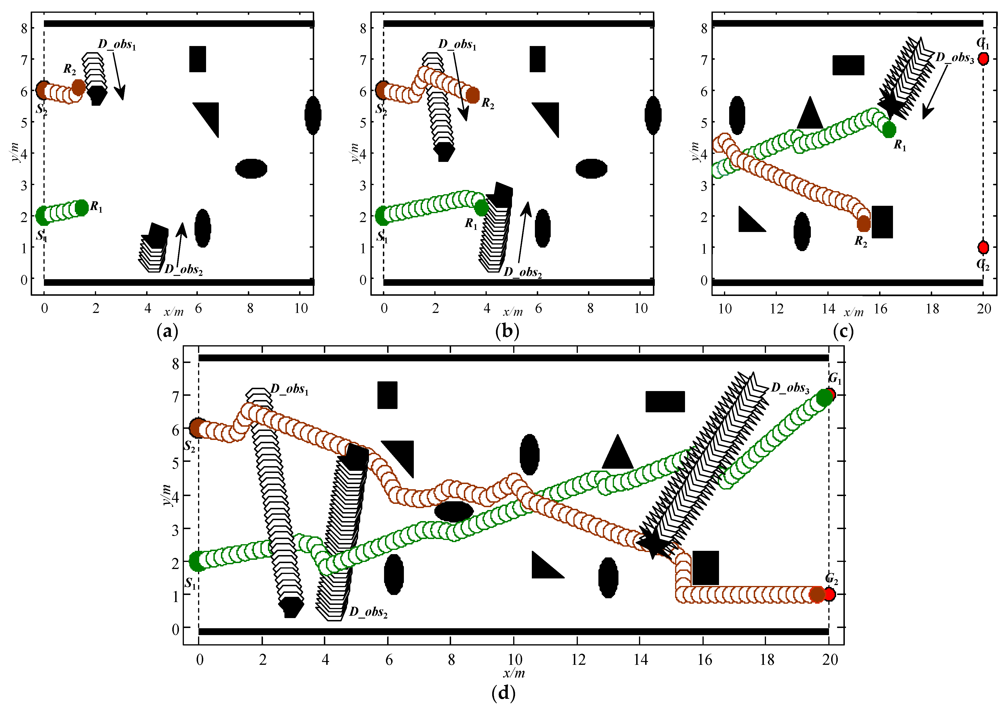
Path planning in static environments can effectively validate the variations in planning capabilities among different immune algorithms. However, in practical applications, dynamic obstacles inevitably exist in the working environments of robots. To validate the effectiveness of the proposed SIRIPPA in dynamic environments, a simulation test for multi-robots was conducted. The dynamic environment is illustrated in Figure 7, featuring two mobile robots, several static obstacles, and three dynamic obstacles approaching from various directions at different velocities. The partial parameters of the dynamic environment are shown in Table 4. It should be noted that, although the paper provides the motion parameters of the dynamic obstacles, the information about the dynamic obstacles in the actual environment was obtained through the robot’s autonomous detection.
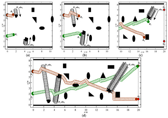
Figure 7.
Path planning results of the SIRIPPA in a dynamic environment. (a) Avoid D_obs1; (b) avoid D_obs2; (c) avoid D_obs3; (d) achieve the goals.

Table 4.
Partial parameters of the dynamic environment.
The entire dynamic planning process is depicted in Figure 7. Figure 7a illustrates that robots R2 and R1 initiate their movements from the starting points S2 and S1, respectively. As initially no obstacles were detected by R1, it moved straight to the goal, G1, demonstrating the uniqueness and stability of antibody selection. R2 encountered the dynamic obstacle D_obs1 quickly and activated the primary immune antibodies. Under the continuous stimulation of the same antigen regarding D_obs1, a large number of antibodies were produced through proliferation and differentiation in a short time relying on the secondary immune response. R2 attempted to avoid D_obs1 by selecting the optimal antibody based on the concentration. Figure 7b shows that R2 successfully avoids D_obs1, and R1 attempts to avoid D_obs2 through the antibody selection. Afterward, R1 and R2 enter the influence range of static obstacles. At this moment, although there are no external dynamic obstacles, the two robots act as dynamic obstacles for each other. They should not only avoid the static obstacles, but also avoid each other at the same time. Figure 7c shows that the two robots avoid static obstacles and each other, and R1 encounters dynamic obstacle D_obs3 again. Unlike the avoidance manner of D_obs2, R1 actively detours D_obs3 from its front. From Figure 7d, it can be observed that the two robots can avoid the static and dynamic obstacles and reach their goals safely, which shows the strong planning capability of the SIRIPPA in dynamic environments.
5. Experiment
5.1. Experimental Environment
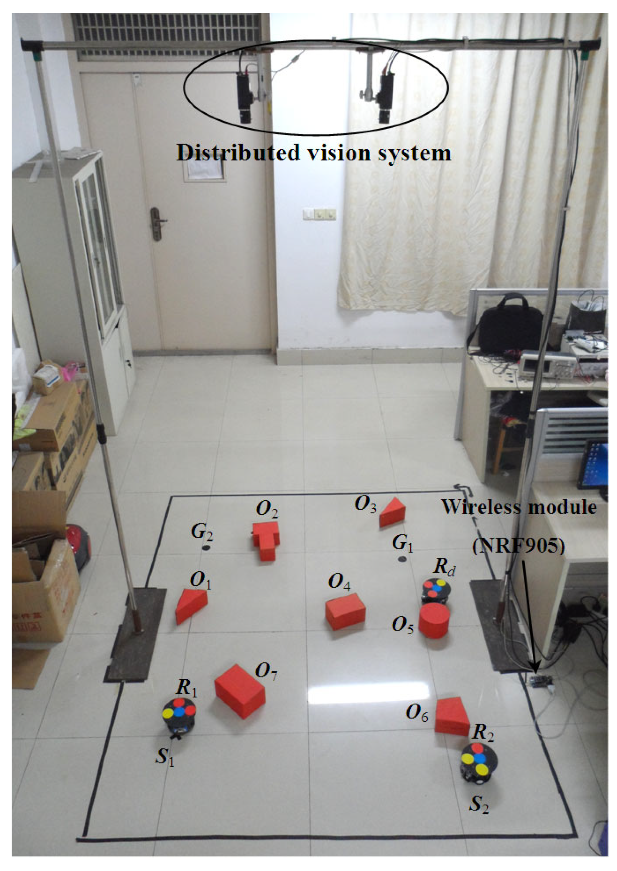
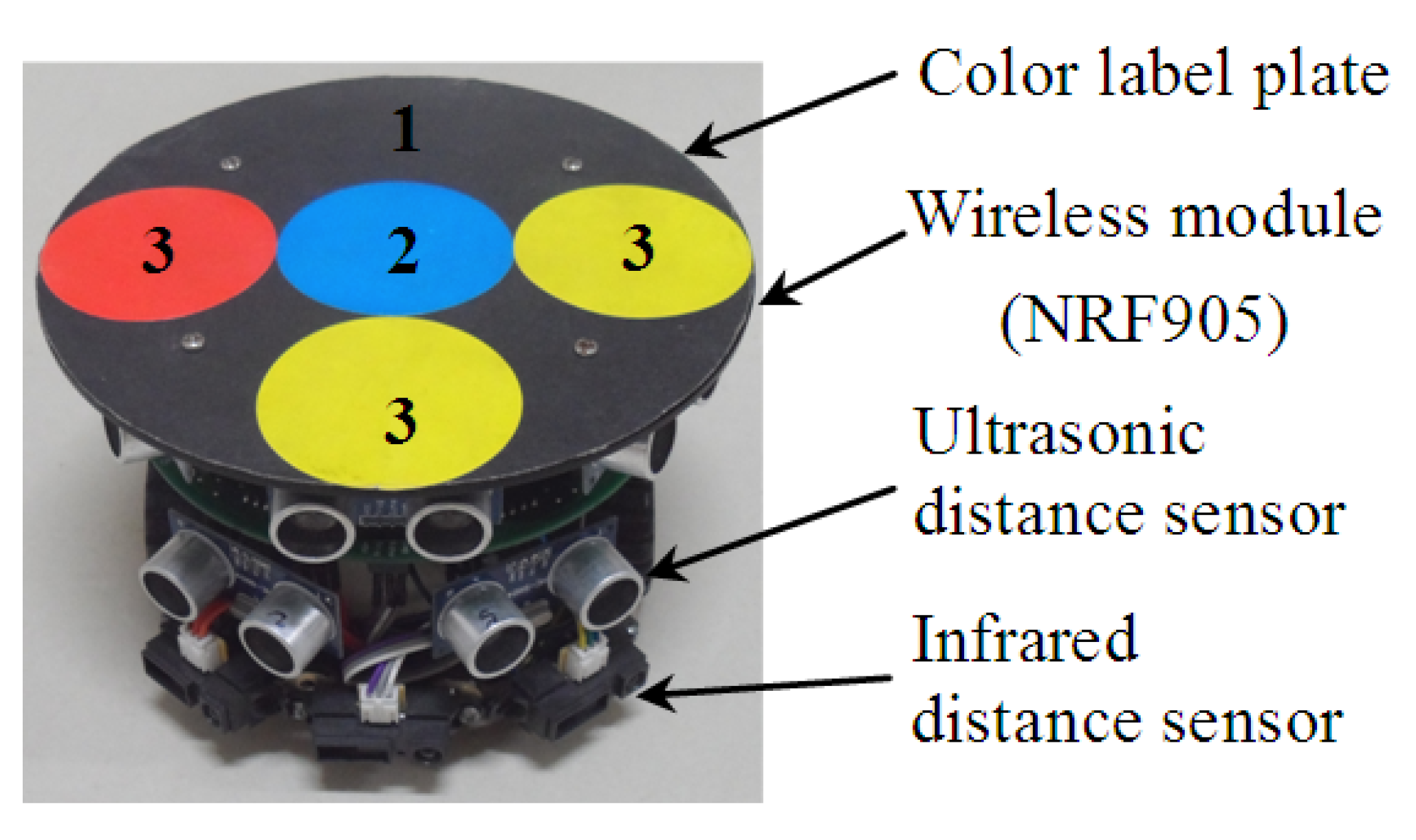
To further verify the validity of the proposed SIRIPPA in a real environment, an online dynamic planning experiment was performed. Figure 8 provides an experimental environment for the path planning of multi-robots, where there are three mobile robots (i.e., R1, R2, and Rd), seven static obstacles (i.e., O1, O2, …, O7), two overhead cameras, a wireless module, and a host computer. Two cameras were used as the global vision system to capture the environment of multi-robots, and the final global environment map was produced based on the image mosaic technique [16]. Figure 9 shows the designed mobile robot, which was driven in the differential mode by connecting two direct motors to two wheels. The mobile robot was equipped symmetrically, but unevenly, with five ultrasonic distance sensors and three infrared distance sensors around it. The ultrasonic sensor model was HC-SR04 and the infrared sensor model was GP2Y0A41SK0F. These sensors were primarily used for rapidly determining whether obstacles were present around the mobile robot. When both the ultrasonic and infrared sensors detected the absence of obstacles in the robot’s surroundings, the distributed vision system did not need to check for obstacle information in that direction. The distributed vision system was activated only when obstacles were detected within the sensor’s coverage area, allowing it to further confirm the specific direction and distance information of the obstacles. To obtain the accurate position and pose information, a color-label plate [17] was installed on the top of the robot, which consisted of one baseplate (black) and four color labels. Label 2 (blue) was the main color label. Label 3 was the auxiliary color label and its color could be red or yellow. The center coordinate of the main color label was defined as the robot coordinate. The direction of the vector between the middle auxiliary color label (i.e., label 3) and main color label (i.e., label 2) was defined as the forward direction of the mobile robot. Different robots could be distinguished according to the different color sequences of three auxiliary color labels. The localizations of three robots were realized based on two overhead cameras, shown in Figure 8.
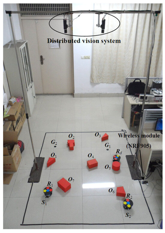
Figure 8.
Experimental environment for path planning.
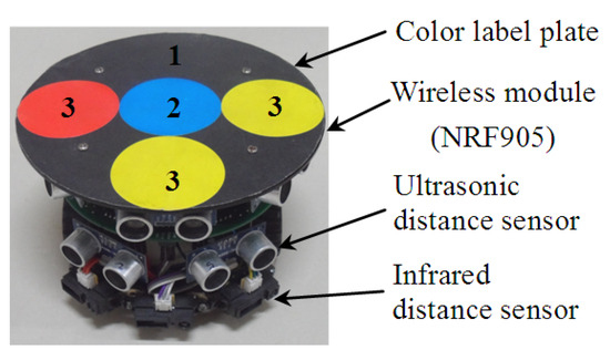
Figure 9.
Mobile robot.
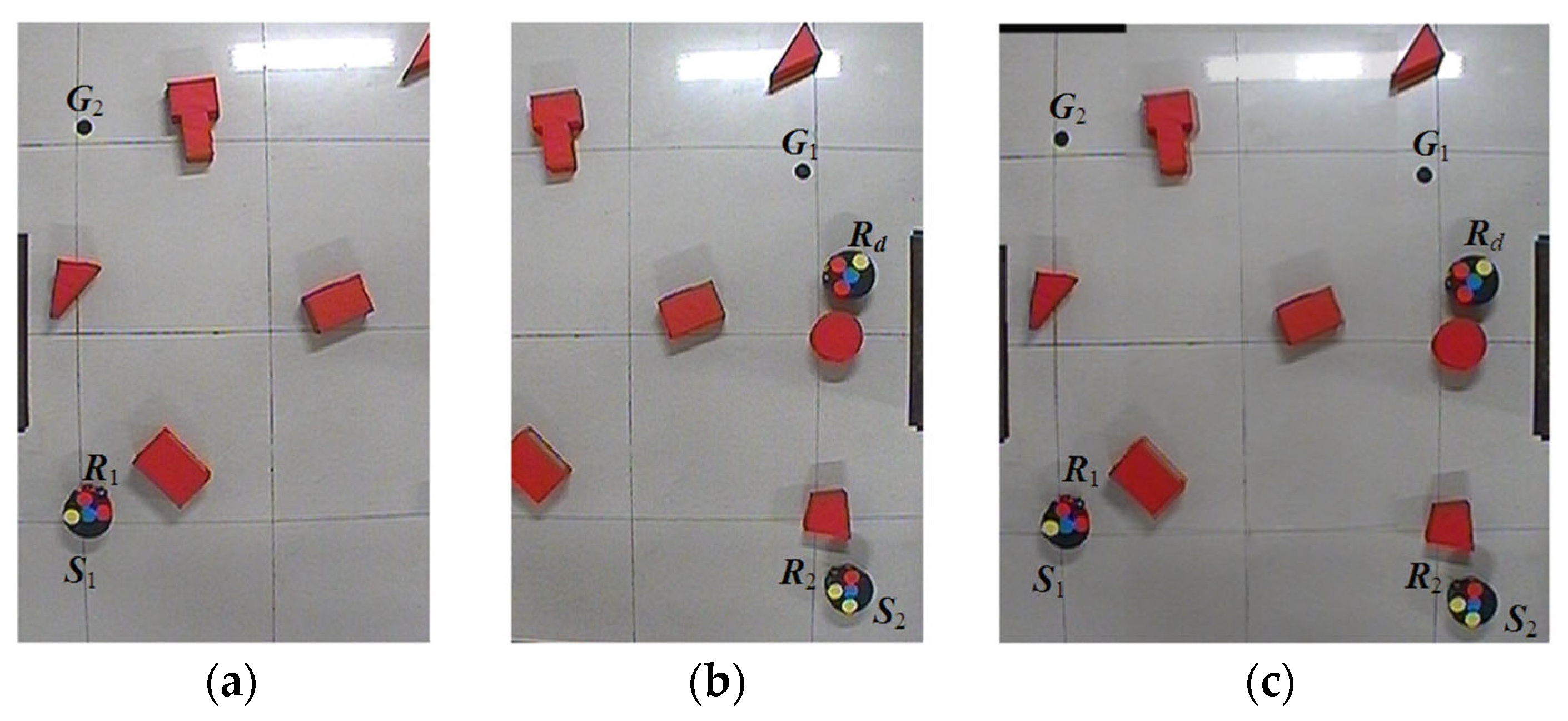
Figure 10a,b show the left and right images captured by the two cameras. Figure 10c shows the whole working environment of the multi-robots after the image mosaic. The experimental requirements can be described as follows: robots R1 and R2 executed the online path planning from S1 and S2 to G1 and G2, respectively, using the proposed SIRIPPA. Robot Rd was considered a dynamic obstacle moving in the environment. All robots could wirelessly communicate with the host computer and receive control commands through the NRF905 wireless module.
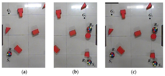
Figure 10.
Acquisition of the robot working environment. (a) Left image; (b) right image; (c) whole working environment.
5.2. Experimental Results
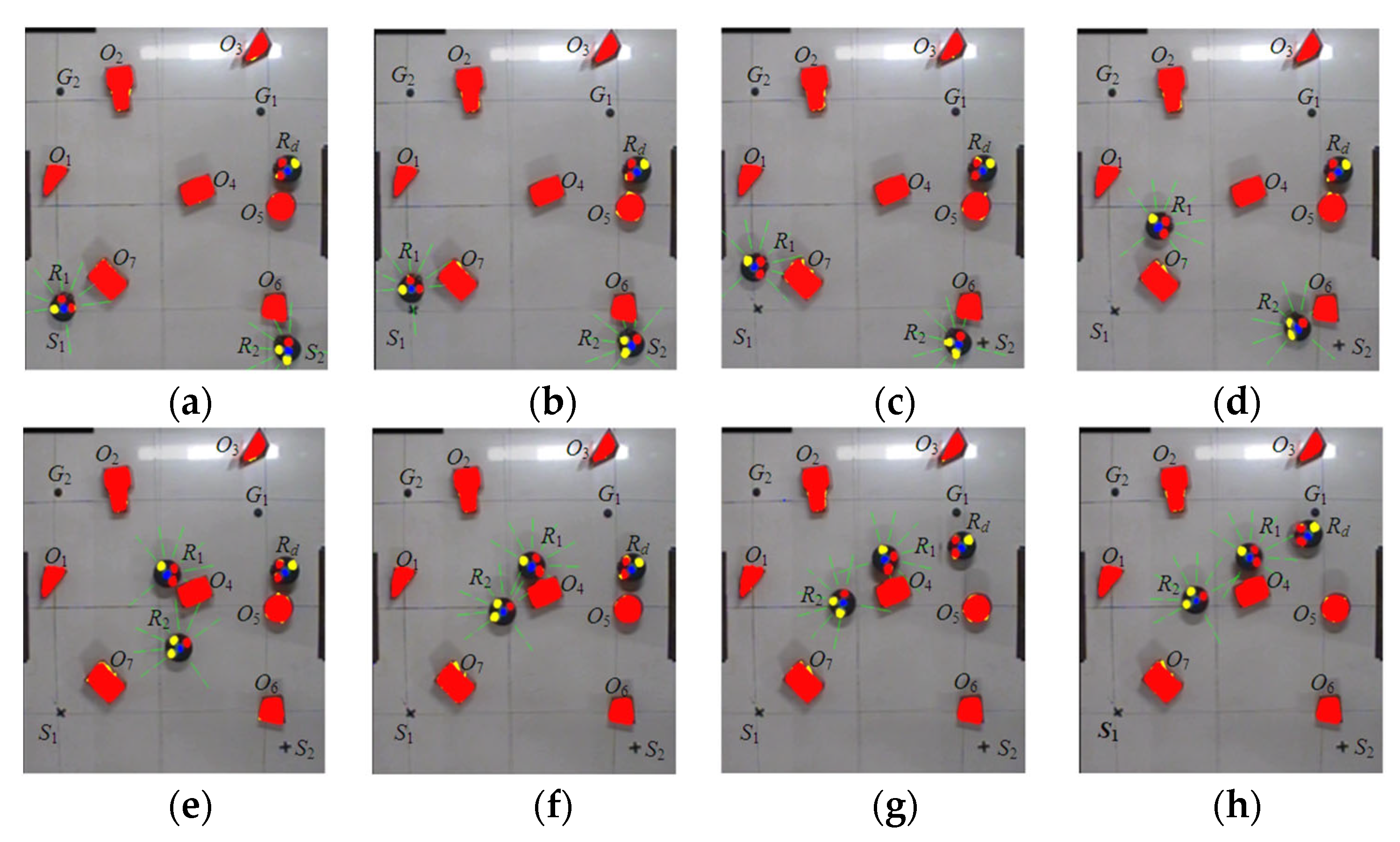
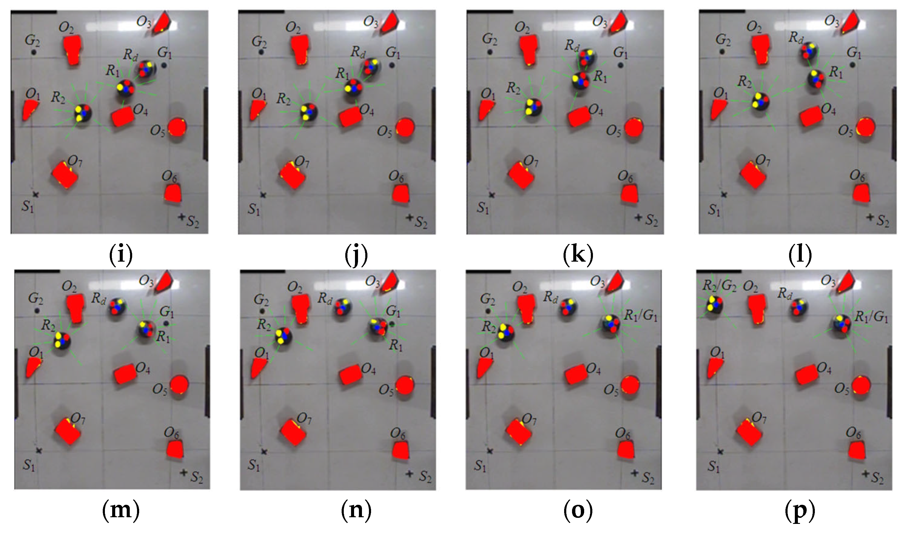
Figure 11 displays the planning outcomes acquired from the experiment. Figure 11a illustrates the initial state of the path planning, where the two robots, R1 and R2, initially detect obstacles O7 and O6, respectively. Taking into account the detected environmental information, R1 endeavors to evade O7 by selecting primary and secondary immune antibodies via the SIRIPPA and proceed towards the goal, G1. Similarly, R2 attempts to avoid O6 and make its way towards the goal, G2. Figure 11b–d show the avoidance process regarding O7 and O6. Figure 11e demonstrates that both R1 and R2 entered the environment of O4. Figure 11f illustrates that the two robots successfully avoided O4. Meanwhile, since the distance between R1 and R2 is less than the detection range of the robot sensors, both R1 and R2 are considered as dynamic obstacles to each other. This implies that R1 or R2 not only have to avoid O4, but also must steer clear of R2 or R1. Figure 11g illustrates that the dynamic obstacle, Rd, initiated its movement and swiftly entered the detection range of R1, as depicted in Figure 11h. Figure 11i–n depict the avoidance process concerning the dynamic obstacle, Rd. At t = 50 s, there are no obstacles in front of R1 and R2, and both robots proceed directly towards their respective goals, as depicted in Figure 11m,n. Figure 11o shows that R1 successfully reached G1, while R2 attained the goal, G2, at t = 60 s, as illustrated in Figure 11p.
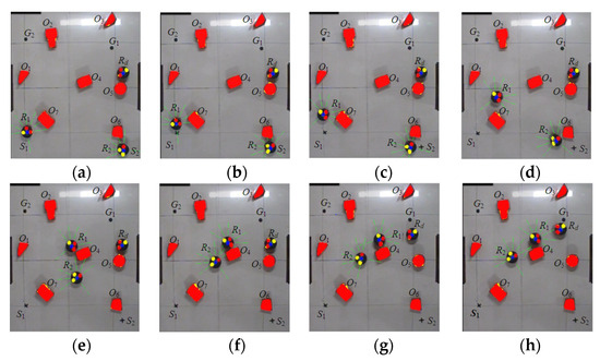
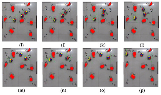
Figure 11.
Experimental results of path planning based on the SIRIPPA. (a) t = 0 s; (b) t = 6 s; (c) t = 10 s; (d) t = 20 s; (e) t = 32 s; (f) t = 36 s; (g) t = 38 s; (h) t = 40 s; (i) t = 41 s; (j) t = 42 s; (k) t = 43 s; (l) t = 45 s; (m) t = 50 s; (n) t = 51 s; (o) t = 53 s; (p) t = 60 s.
6. Conclusions
Indeed, path planning is a crucial task in the autonomous navigation of mobile robots. Effective path planning algorithms and techniques enable robots to navigate safely and efficiently in complex and dynamic environments. To enhance the path planning performance of multi-robots in dynamic environments, we proposed a new algorithm called the secondary immune response-based immune path planning algorithm. This algorithm builds upon the basic immune path planning framework and introduces secondary immune responses to better handle complex and changing environments. By incorporating this approach, we aimed to improve the adaptability, robustness, and efficiency of path planning for multiple robots operating in dynamic scenarios. The following conclusions can be drawn from the results of the simulations and experiment:
- During the primary immune stage, the antibodies were designed solely based on the obstacle antigen. This approach effectively avoided the constraint of the goal antigen in the antibody selection stage, increasing the probability that the primary immune antibodies were activated.
- Inspired by the secondary immune response, a large number of immune antibodies were proliferated and differentiated. As a result, the corresponding turning angles of a mobile robot were subdivided, which helped to reduce the turning magnitude of the robots for obstacle avoidance and improved the flexibility of the immune planning algorithm. This approach enabled the robots to adapt more effectively to dynamic environments and achieve a better path planning performance.
- Based on the Farmer’s immune kinetic model, the proposed secondary immune kinetic model further enhanced the rationality of antibody selection. This improvement was achieved by integrating the influence of both the obstacle antigen and goal antigen on the secondary immune antibodies. By considering both factors, the algorithm could make more informed decisions during the antibody selection process, leading to an improved path planning performance in dynamic environments.
- Compared to the IMGA, GA-ACO, and GA-PSO algorithms, the simulation results in four static environments demonstrated that the proposed SIRIPPA algorithm exhibited shorter path lengths and greater smoothness in the planned paths. Moreover, the simulation test involving two robots in a dynamic environment showcased the flexibility and stability of the SIRIPPA in uncertain environments. Finally, the online experiment conducted in a real environment served as further verification of the effectiveness of the proposed SIRIPPA algorithm.
Author Contributions
Methodology, Y.J. and M.Y.; validation, Y.J., L.Z. and Y.S.; original draft preparation, Y.J. and M.Y.; writing, Y.J. and L.Z. All authors have read and agreed to the published version of the manuscript.
Funding
This research was funded by the High-tech Ship Scientific Research Project from the Ministry of Industry and Information Technology ([2019]360) and the 2023 Zhangjiagang City Industry University Research Pre-Research Fund Project (ZKYY2328).
Data Availability Statement
Data are contained within the article.
Conflicts of Interest
The authors declare no conflicts of interest.
References
- Kumar, S.; Sikander, A. Optimum mobile robot path planning using improved artificial bee colony algorithm and evolutionary programming. Arab. J. Sci. Eng. 2022, 47, 3519–3539. [Google Scholar] [CrossRef]
- Zhai, L.; Feng, S. A novel evacuation path planning method based on improved genetic algorithm. J. Intell. Fuzzy Syst. 2022, 42, 1813–1823. [Google Scholar] [CrossRef]
- Sadiq, A.T.; Raheem, F.A.; Abbas, N. Ant colony algorithm improvement for robot arm path planning optimization based on D* strategy. Int. J. Mech. Mechatron. Eng. 2021, 21, 96–111. [Google Scholar]
- Sarkar, R.; Barman, D.; Chowdhury, N. Domain knowledge based genetic algorithms for mobile robot path planning having single and multiple targets. J. King Saud Univ.-Comput. Inf. Sci. 2022, 34, 4269–4283. [Google Scholar] [CrossRef]
- Szczepanski, R.; Bereit, A.; Tarczewski, T. Efficient local path planning algorithm using artificial potential field supported by augmented reality. Energies 2021, 14, 6642. [Google Scholar] [CrossRef]
- Lin, Z.; Yue, M.; Chen, G.; Sun, J. Path planning of mobile robot with PSO-based APF and fuzzy-based DWA subject to moving obstacles. Trans. Inst. Meas. Control 2022, 44, 121–132. [Google Scholar] [CrossRef]
- Li, Q.; Gama, F.; Ribeiro, A.; Prorok, A. Graph neural networks for decentralized multi-robot path planning. In Proceedings of the 2020 IEEE/RSJ International Conference on Intelligent Robots and Systems (IROS), Las Vegas, NV, USA, 24 October 2020. [Google Scholar]
- Ma, G.; Duan, Y.; Li, M.; Xie, Z.; Zhu, J. A probability smoothing Bi-RRT path planning algorithm for indoor robot. Future Gener. Comput. Syst. 2023, 143, 349–360. [Google Scholar] [CrossRef]
- Li, K.; Hu, Q.; Liu, J. Path planning of mobile robot based on improved multiobjective genetic algorithm. Wirel. Commun. Mob. Comput. 2021, 2021, 8836615. [Google Scholar] [CrossRef]
- Shi, K.; Huang, L.; Jiang, D.; Sun, Y.; Tong, X.; Xie, Y.; Fang, Z. Path planning optimization of intelligent vehicle based on improved genetic and ant colony hybrid algorithm. Front. Bioeng. Biotechnol. 2022, 10, 905983. [Google Scholar] [CrossRef] [PubMed]
- Sabiha, A.D.; Kamel, M.A.; Said, E.; Hussein, W.M. Real-time path planning for autonomous vehicle based on teaching–learning-based optimization. Intell. Serv. Robot. 2022, 15, 381–398. [Google Scholar] [CrossRef]
- Lin, S.; Liu, A.; Wang, J.; Kong, X. A review of path-planning approaches for multiple mobile robots. Machines 2022, 10, 773. [Google Scholar] [CrossRef]
- Mohanty, P.K.; Kodapurath, A.A.; Singh, R.K. A hybrid artificial immune system for mobile robot navigation in unknown environments. Iran. J. Sci. Technol. Trans. Electr. Eng. 2020, 44, 1619–1631. [Google Scholar] [CrossRef]
- Cho, S.; Shrestha, B.; Jang, W.; Seo, C. Trajectory tracking optimization of mobile robot using artificial immune system. Multimed. Tools Appl. 2019, 78, 3203–3220. [Google Scholar] [CrossRef]
- Kim, T.O.; Despotovic, J.M. Primary and secondary immune cytopenias: Evaluation and treatment approach in children. Hematol./Oncol. Clin. 2019, 33, 489–506. [Google Scholar] [CrossRef] [PubMed]
- Tang, Z.; Xu, L.; Xie, H. Picking trajectory planning of citrus based on improved immune algorithm and binocular vision. In Proceedings of the 2020 IEEE International Conference on Artificial Intelligence and Computer Applications (ICAICA), Dalian, China, 27–29 June 2020. [Google Scholar]
- Zhao, R.; Yuan, M.; Hua, X.; Shen, Y. Visual segmentation and localization of mobile robots based on the feedback regulation. IOSR J. VLSI Signal Process. 2014, 4, 1–6. [Google Scholar] [CrossRef]
Disclaimer/Publisher’s Note: The statements, opinions and data contained in all publications are solely those of the individual author(s) and contributor(s) and not of MDPI and/or the editor(s). MDPI and/or the editor(s) disclaim responsibility for any injury to people or property resulting from any ideas, methods, instructions or products referred to in the content. |
© 2024 by the authors. Licensee MDPI, Basel, Switzerland. This article is an open access article distributed under the terms and conditions of the Creative Commons Attribution (CC BY) license (https://creativecommons.org/licenses/by/4.0/).

