Abstract
The inadequacy of conventional control strategies for multi-phase interleaved parallel circuits in terms of adaptive adjustment makes it difficult to meet the power source design requirements for transient electromagnetic detection systems. This paper introduces a novel approach, the variable-domain fuzzy proportional–integral (PI) adaptive control strategy. This strategy dynamically adjusts the fuzzy domain in real time based on the input error magnitude, ensuring improved control effectiveness. By leveraging the benefits of both the functional scaling factor and the fuzzy reasoning scaling factor, we design scaling factors for the input and output domains to enhance control precision. The focus of this study is on a four-phase interleaved parallel converter, emphasizing the design of the variable-domain fuzzy PI control strategy for the voltage outer loop within the traditional dual closed-loop structure. An experimental prototype with a 220 Vac input, 380 V output, and a power rating of 1000 W is constructed. A comparative analysis between fuzzy control and variable-domain fuzzy PI control is conducted in the voltage outer loop of the dual closed-loop control. Results reveal that dual closed-loop control with variable-domain fuzzy PI control for the voltage outer loop significantly enhances system stability. The startup time to reach the steady state is reduced to 0.632 s, with an overshoot of 28.8 V. Transitioning from 25% load to full load takes only 0.096 s, resulting in a minimal drop of 21.4 V and an overshoot of 13.4 V. Similarly, switching from full load to 25% load in 0.167 s exhibits an overshoot of only 19.6 V. The adaptive regulation capability of the converter is markedly improved, showcasing smaller overshoots and higher-level controlling effectiveness.
1. Introduction
Pulse power sources play a crucial role in transient electromagnetic detection systems, where they are required to produce power current pulses with a typical bipolar square waveform. These pulses exhibit high current amplitudes, reaching several hundred amperes, and voltage levels up to 1 kilovolts. In aerospace applications of transient electromagnetic systems, the peak power output often falls within the range of 500 kW to 1000 kW, a notable contrast to the generator output power, which typically remains below 10 kW [1,2]. Given the nature of their applications, the power source’s current pulses must undergo frequent switches between heavy and light loads. Enhancing the regulator’s capability and ensuring the stability of the pulse source are paramount for optimal performance [3]. Additionally, as these pulse power sources serve as excitation signal generators for transient electromagnetic systems, they are subjected to strict requirements regarding the output current ripple. Minimizing ripple becomes essential to mitigate signal noise in the excitation response, thereby significantly improving the overall signal-to-noise ratio of the system.
Power converters with a multi-phase interleaved parallel structure exhibit low ripple characteristics [4], enabling them to be particularly suitable for high-quality power signal sources. However, research on high-dynamic-response control strategies for strong impulse load variations is still lacking. In the literature [5], an adaptive output feedback controller has been developed for an interleaved parallel converter with load variations over time. This controller estimated online current and variable resistance to meet output voltage reference tracking for changing loads but failed to effectively reduce overshoot. The literature [6] proposes an optimization method for dynamic response based on model predictive control, whereas the decoupling process is cumbersome and not suitable for working environments of higher complexities. The literature [7] employs a “K factor” design method and particle swarm optimization to design a loop controller, maintaining overall stability and generating satisfactory dynamic responses. The literature [8] proposed a fuzzy high-order sliding mode control to improve dynamic qualities and effectively address the oscillation issues but could not simultaneously guarantee steady-state performance. The literature [9] suggests that a converter using dual-loop fuzzy PI control had lower overshoot and faster steady-state recovery but exhibited limited adaptive adjustment capability when subjected to external disturbances, making it less suitable for scenarios requiring frequent load switching. While these studies have shown positive outcomes in terms of response speed or overshooting, they basically focus on individual aspects yet fail to provide comprehensive solutions for pulsed power sources operating under conditions of repeated switches between heavy and light loads. Such a scenario necessitates the maintenance of good dynamic characteristics, which entails fast responses for stability restoration and minimal voltage variations.
Considering the demands of the detector power supply, a control strategy capable of addressing the dynamic performance of the output voltage of a multi-phase interleaved shunt converter is essential. Traditional PI control, widely used and characterized by its effectiveness, has met some limitations, and introducing the fuzzy PI control algorithm enhances accuracy adjustment and adaptability compared to such control. Furthermore, the variable-domain fuzzy PI control method, an improved version of fuzzy PI control, incorporates a scaling factor to regulate its domain based on fuzzy control, imparting excellent self-adaptive ability. This method is further enhanced by the variable domain, which introduces an expansion factor for superior adaptive ability and control effectiveness, particularly suitable for systems with frequently changing working status.
This paper endeavors to introduce a variable-domain fuzzy PI-controlled power source, on which prior research is limited. The correctness and feasibility of the proposed scheme are validated through simulations and experimentation, addressing the current research gap in such domain. The paper also delves into the power source circuit structure and modal analysis.
2. Topological Structure
A multi-phase interleaved parallel converter, while ensuring the equal current distribution among its branches, can theoretically extend to an infinite number of branches [10,11]. By setting the number of branches as N, it is observed that the peak value of the output voltage ripple decreases with an increasing number of branches. Significant improvement in reducing the ripple peak value is achieved when 1 ≤ N ≤ 4. However, as N ≥ 4, the enhancement in reducing the ripple peak value becomes less substantial. When N ≥ 6, the converter’s gain starts to decrease.
Practical applications of multi-phase interleaved parallel structures pose challenges such as addressing current equalization issues, managing increased control system complexity, dealing with higher volume and cost, and ensuring reliability. To strike a balance between advantages and challenges, the four-phase interleaved parallel structure is selected as the main circuit topology.
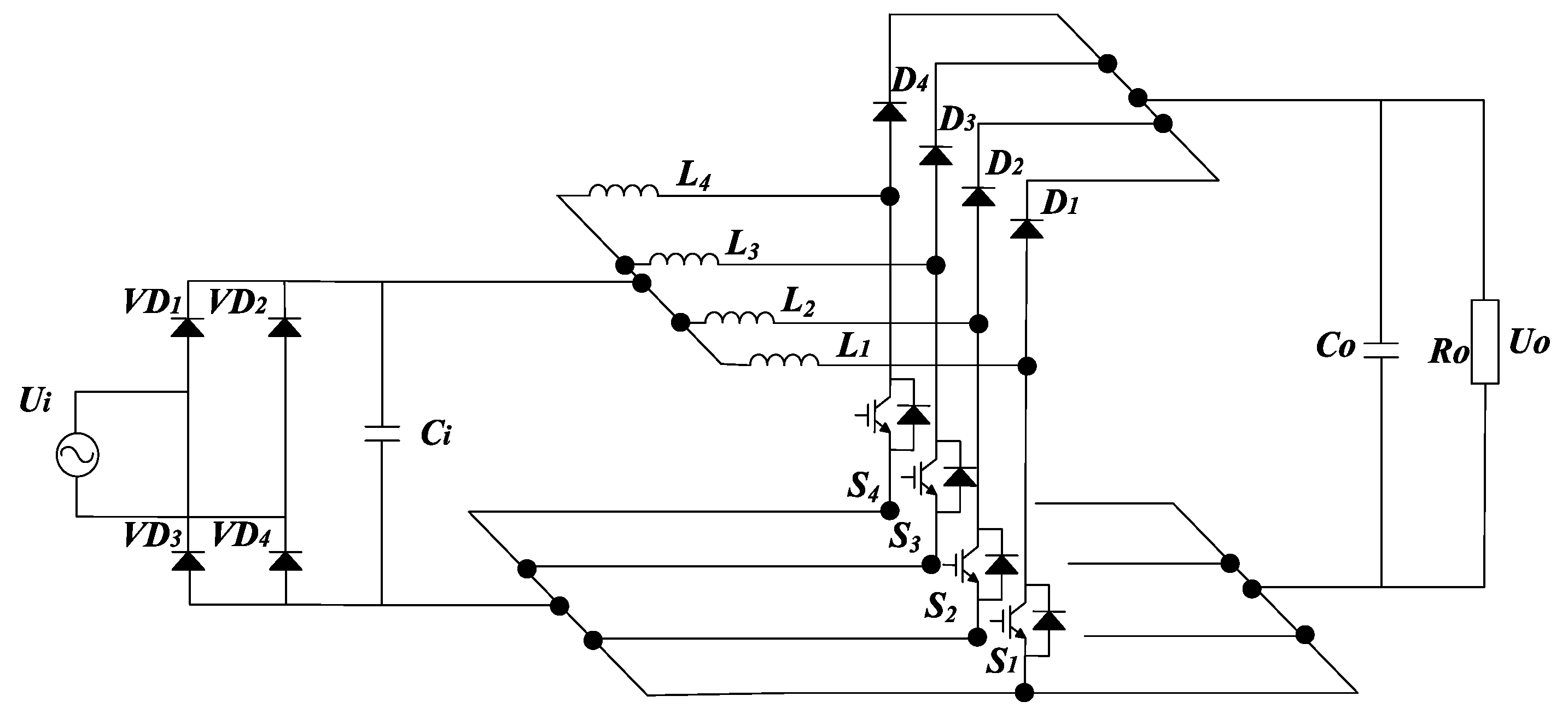
In Figure 1, an N = 4 interleaved parallel structure—a four-phase interleaved parallel Boost circuit—is depicted. This configuration includes four rectifier diodes forming the rectifier bridge, input filter capacitors, four inductors, four Mosfet tubes, four sets of diodes, filter capacitors, and the equivalent load. The four identical Boost circuits are connected in parallel, with each of the four branches spaced 90° apart. To maintain consistency in power and current values across each branch, device parameters are standardized in each branch, and the power in each branch is one fourth of the power at the load end.
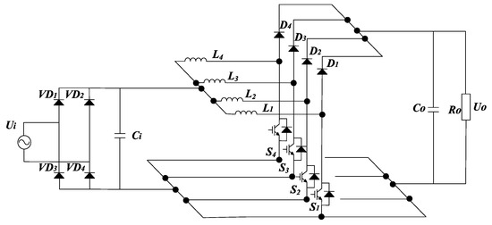
Figure 1.
Topology of the four-phase interleaved parallel converter (N = 4).
Modal Analysis
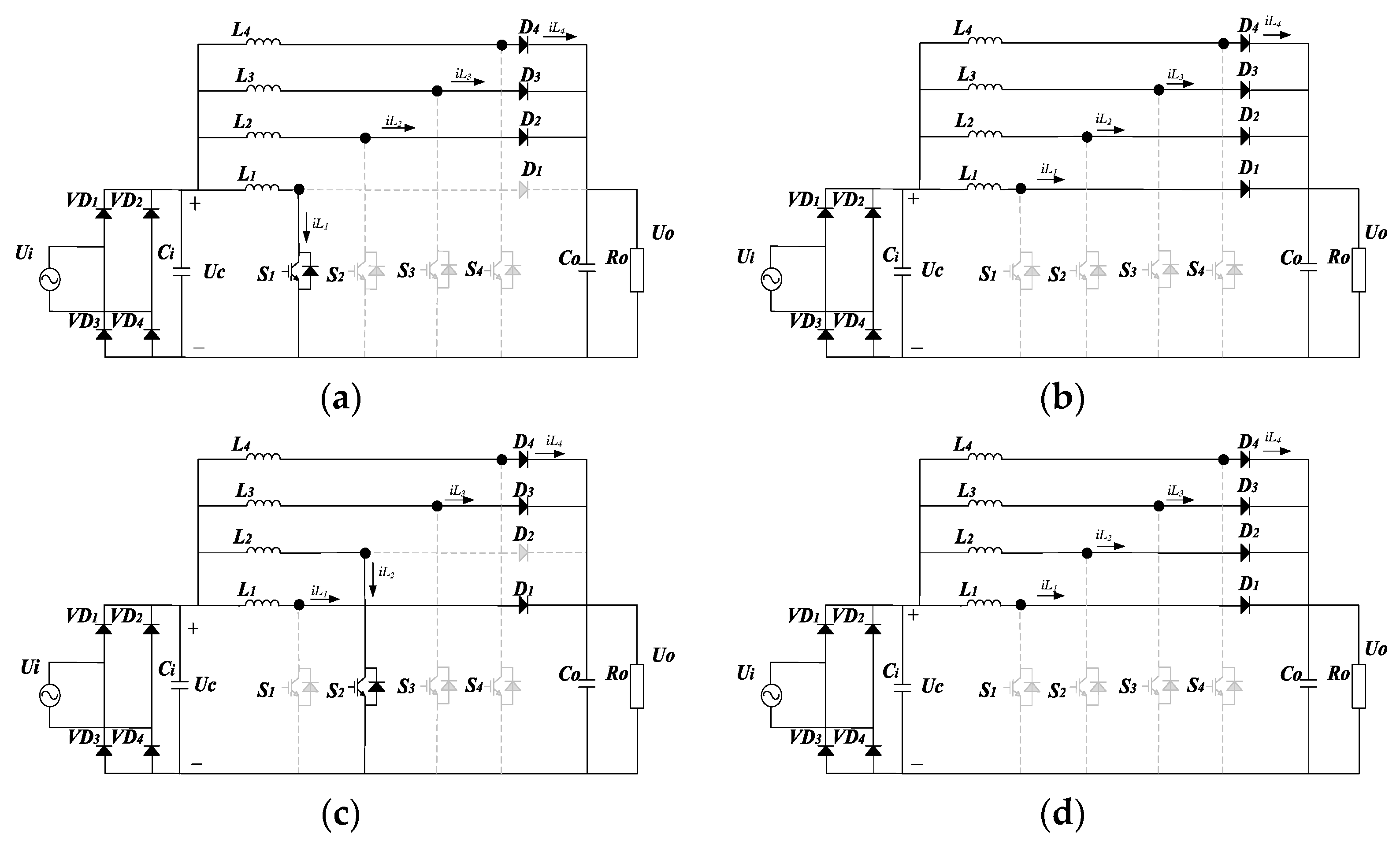
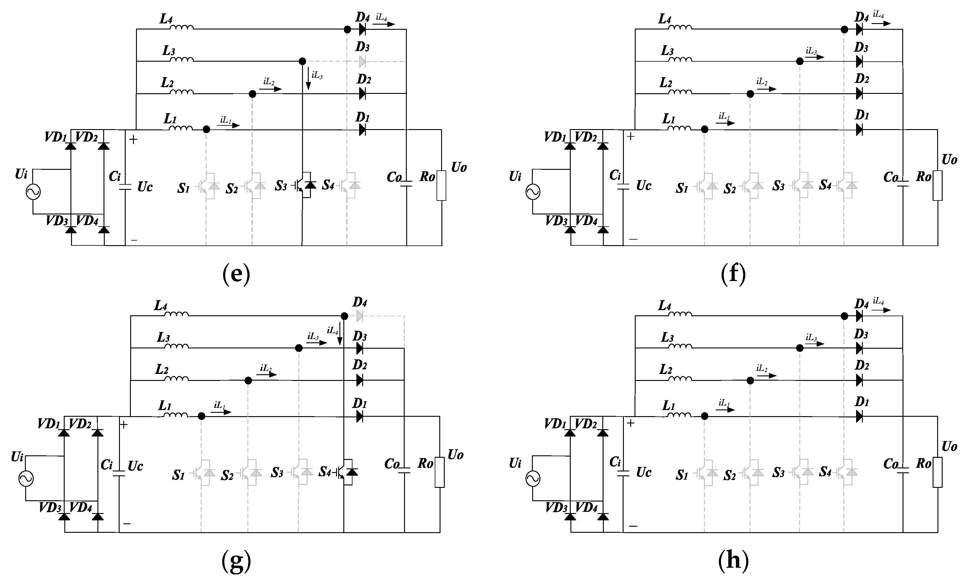
The driving signals for the four MOSFET switches in the four-phase interleaved parallel converter exhibit a 90° phase difference [12,13]. Consequently, the duty cycle can be divided into four intervals: 0 < D ≤ 0.25, 0.25 < D ≤ 0.5, 0.5 < D ≤ 0.75, and 0.75 < D ≤ 1. Different operating modes of the converter occur in these intervals. Considering the design requirement of a boost ratio of 0.18, the analysis focuses on the interval 0 < D ≤ 0.25. In this duty cycle interval, the four-phase interleaved parallel converter operates in eight modes within one cycle, and the corresponding equivalent circuit diagrams are illustrated in Figure 2.
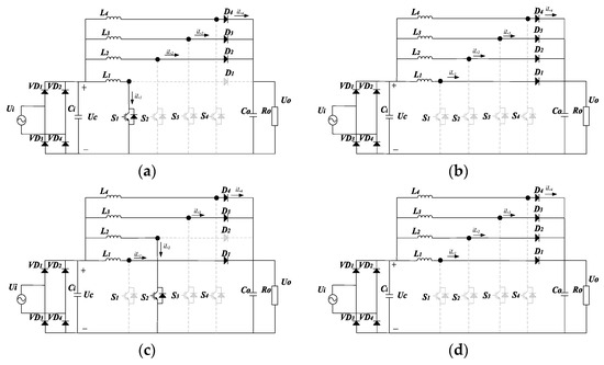
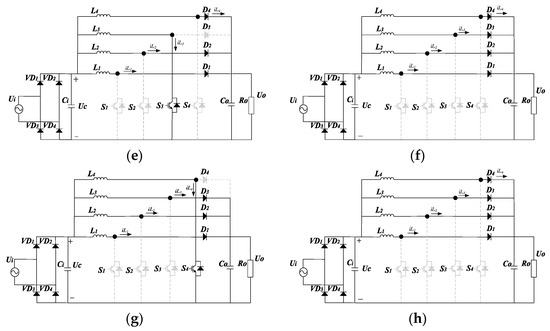
Figure 2.
Equivalent circuits for eight modes in one cycle: (a) mode 1; (b) mode 2; (c) mode 3; (d) mode 4; (e) mode 5; (f) mode 6; (g) mode 7; (h) mode 8.
If the input and output voltage ripples are disregarded, and the four inductors L1–4 are assumed to be of the same inductance L, a modal analysis yields the following results (The inductances appearing in the following equations are denoted by L):
- (1)
- Mode 1: Mosfet S1 is on, S2, S3, S4 is off, diode D1 is off, and D2, D3, D4 are on. The input AC voltage Ui is rectified and filtered, and the resulting DC voltage Uc is added to both ends of the boost inductor. In this mode, charging occurs, and inductor current iL1 increases linearly with the speed of Uc/L. Boost inductors L2, L3, L4, the output filter capacitor Co charge, and the output load power Ro are supplied. Inductor currents iL2, iL3, iL4 decrease linearly with the speed of Uc/L.
- (2)
- Mode 2: Mosfet S1, S2, S3, S4 are off, and diode D1, D2, D3, D4 are on. Input AC voltage is the same as the output voltage . Boost inductors L1, L2, L3, L4 charge output filter capacitor Co and supply power to the output load . Inductor currents iL1, iL2, iL3, iL4 decrease linearly. Modes 4, 6, and 8 are consistent with Mode 2 and will not be separately analyzed.
- (3)
- Mode 3: Mosfet S2 is on, S1, S3, S4 are off, diode D2 is off, and D1, D3, D4 are on. The input AC voltage is rectified and filtered, and the resulting DC voltage is added to both ends of the boost inductor. Charging occurs, and inductor current iL2 increases linearly. Boost inductors L1, L3, L4, the output filter capacitor Co charge, and the output load power are supplied. Inductor currents iL1, iL3, iL4 decrease linearly with the speed of Uc/L.
- (4)
- Mode 5: Mosfet S3 is on, S1, S2, S4 are off, diode D3 is off, and D1, D2, D4 are on. Similar to Modes 1 and 3, charging occurs with the increase in inductor current (iL3). Boost inductors L1, L2, L4, the output filter capacitor Co charge, and the output load power are supplied. Inductor currents iL1, iL2, iL4 decrease linearly with the speed of Uc/L.
- (5)
- Mode 7: Mosfet S4 is on, S1, S2, S3 are off, diode D4 is off, and D1, D2, D3 are on. Similar to Modes 1, 3, and 5, charging occurs with the increase in inductor current (iL4). Boost inductors L1, L2, L3, the output filter capacitor Co charge, and the output load power are supplied. Inductor currents iL1, iL2, iL3 decrease linearly with the speed of Uc/L.
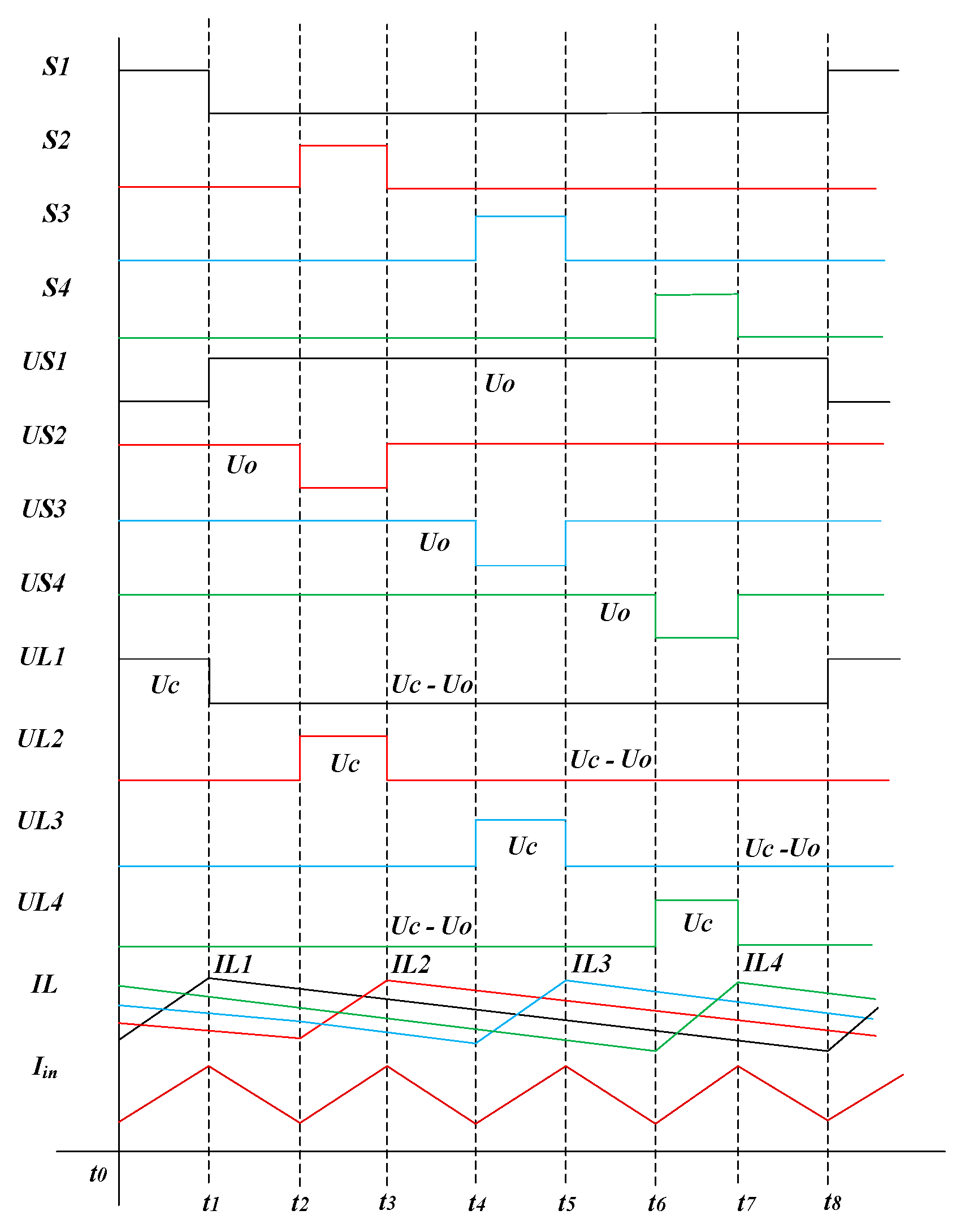
Analyzing the eight modes within one switching cycle, the main waveforms of the four-phase interleaved parallel converter during one cycle T can be plotted, as shown in Figure 3. From Figure 3, it is evident that when MOSFET switch is turned on, the voltage across the switch terminals is the input filter capacitor Ci voltage . When is turned off, the voltage across the switch terminals is the output load voltage . As the converter is a boost circuit, the output voltage is always greater than or equal to the input DC side voltage . Device selection should ensure a voltage tolerance greater than 1.5 Uo, leaving a 50% margin for maximum stress. Through the analysis of the converter modes and the main waveform analysis, it is observed that the four inductor currents do not always rise or fall simultaneously at any given moment. This working state reduces the input current ripple of the four-phase interleaved parallel converter, which reflects the effective reduction of current ripple and current stress on electronic devices. Furthermore, the input current period is reduced to one fourth of the original, and the frequency is quadrupled, contributing to improved filtering effectiveness.
Figure 3.
Main waveforms of the four-phase interleaved parallel converter. (Black, red, green, and blue are used to indicate various physical quantity states for channels 1–4, respectively.)
3. Control Strategy of Converter System Based on Fuzzy PI Control
The four-phase interleaved shunt converter adopts a double-loop control strategy of inductor current inner-loop PI control and output voltage outer-loop fuzzy PI control. In this strategy, the design of the voltage outer-loop fuzzy controller involves presetting the initial PI parameters of the fuzzy controller through the transfer function. Subsequently, the fuzzy PI control parameters are obtained through the inference of the designed fuzzy controller.
3.1. Presetting of Fuzzy PI Control Parameters
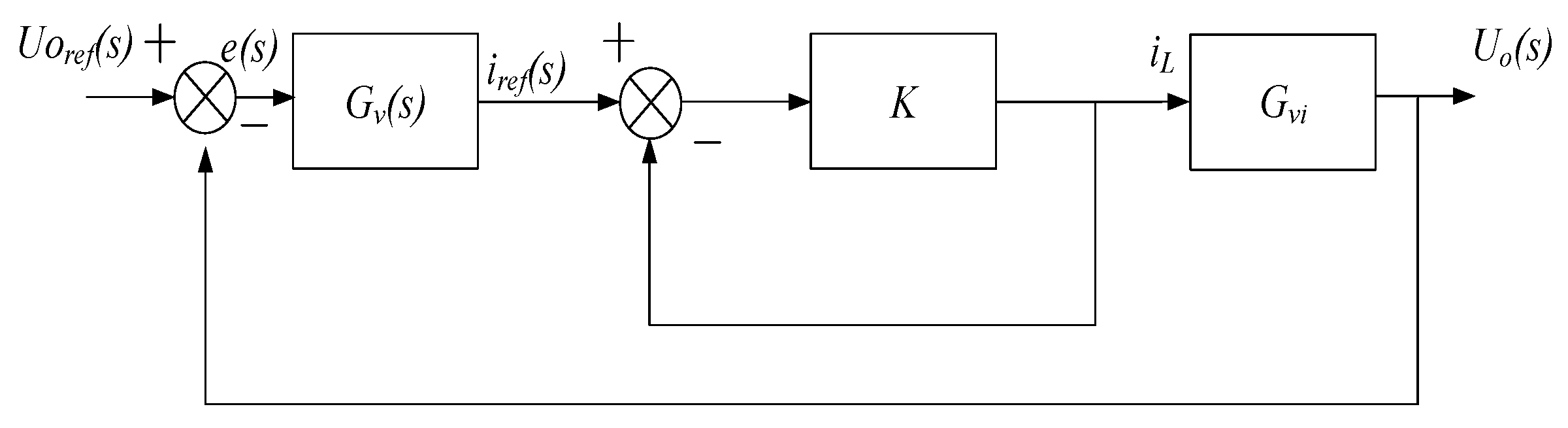
In order to derive precise PI control parameters for the multi-phase interleaved parallel converter, a model of the converter is established. The traditional PI control principle block diagram for the converter’s output voltage is illustrated in Figure 4. In order to derive precise PI control parameters for the multi-phase interleaved parallel converter, a model of the converter is established. The traditional PI control principle block diagram for the converter’s output voltage is illustrated in Figure 4.
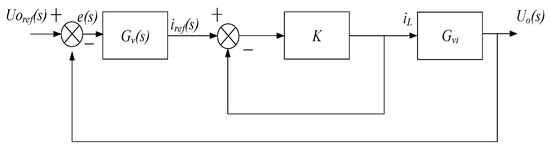
Figure 4.
Block diagram of the control principle for the four-phase interleaved parallel converter.
In Figure 4, is the output voltage compensation transfer function, K is the compensated current inner loop transfer function (treated as a constant for analysis), and is the transfer function from inductor current to output voltage. The expressions for these functions are given as follows:
In Equations (1)–(4), refers to the inductor current compensation proportional coefficient, the compensation integral coefficient, (s) the duty cycle to inductor current transfer function, and (s) the converter duty cycle to output voltage transfer function.
The open-loop transfer function for the four-phase interleaved parallel converter’s voltage outer loop is as follows:
To achieve good dynamic performance, by presetting phase margin and gain margin, we can derive:
In Equations (6) and (7), PM is the target phase angle, and f is the desired crossing frequency.
3.2. Design of Fuzzy PI Controller
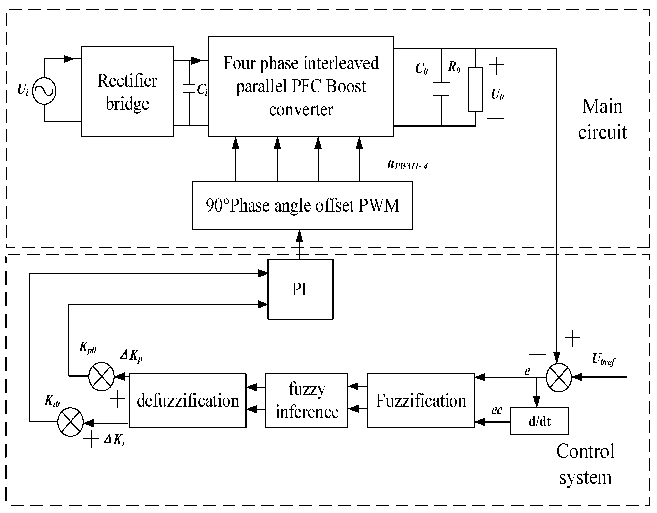
The structure of the converter circuit system based on fuzzy PI control consists of a main circuit and the fuzzy PI controller, as shown in Figure 5.
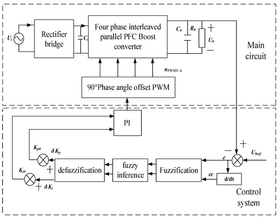
Figure 5.
System diagram of the four-phase interleaved parallel converter based on fuzzy PI control.
The fuzzy PI controller considers the output voltage as the controlled object, taking the error (e) between the output voltage and its ideal reference value and its error rate of change () as the two input quantities for the fuzzy controller [14,15]. First, the parameters are fuzzified by setting a unified fuzzy physical theory domain range to [−Em, Em]. Triangular membership functions are employed as the membership functions for the fuzzy PI control, with fuzzy sets {NB, NM, NS, ZE, PS, PM, PB} corresponding to linguistic variables {negative large, negative medium, negative small, zero, positive small, positive medium, positive large} [16,17,18]. The proportional and integral coefficients obtained after tuning the fuzzy PI controller are given by the following:
where and are the output proportional and integral coefficients of the controller after tuning, and are the clear values obtained after fuzzy processing for the input error e and error rate .
Depending on different voltage error e and voltage error rate values, the direction of adjustment for voltage loop control parameters varies. Considering a balance between reducing overshoot and shortening dynamic response time, the design of fuzzy rule tables is particularly important.
The rules of control design are obtained from the literature [9], and a table of fuzzy rules is proposed as shown in Table 1 and Table 2.

Table 1.
Fuzzy rules for .
Table 2.
Fuzzy rules for .
After obtaining the fuzzy rule outputs and , it is necessary to obtain precise control values through defuzzification. The primary defuzzification methods include the maximum membership principle, centroid method, and weighted average method [16]. Among these methods, the centroid method is chosen for its smoother output reasoning control. The centroid method formula is given by the following:
In Equation (10), C represents the centroid position of the fuzzy set, x is the error e or the rate of change of the error ec, and μ(x) denotes the membership degree of variable x.
4. Converter Control Strategy Based on Variable-Domain Fuzzy PI Control
Compared to traditional PI control, fuzzy PI control demonstrates excellent disturbance rejection capabilities against external interference [17], variations of process parameters, and nonlinear factors, which possess strong robustness. However, it faces challenges in meeting the rapid adjustment to a steady state when transient electromagnetic system power sources encounter disturbances in practical applications. To further enhance the dynamic performance of the transformer used for power source transformation, it is necessary to improve the design of the fuzzy PI controller. Therefore, a variable-domain fuzzy PI control method that can adaptively change the domain is proposed.
The variable-domain fuzzy PI control system enhances the adaptability and control effectiveness when facing disturbances by introducing a scaling factor to adjust its domain, building upon the foundation of the fuzzy PI control system [18,19,20]. Therefore, a control strategy for a four-phase interleaved parallel converter system based on variable-domain fuzzy PI control is put forward.
4.1. Variable Domain Concept
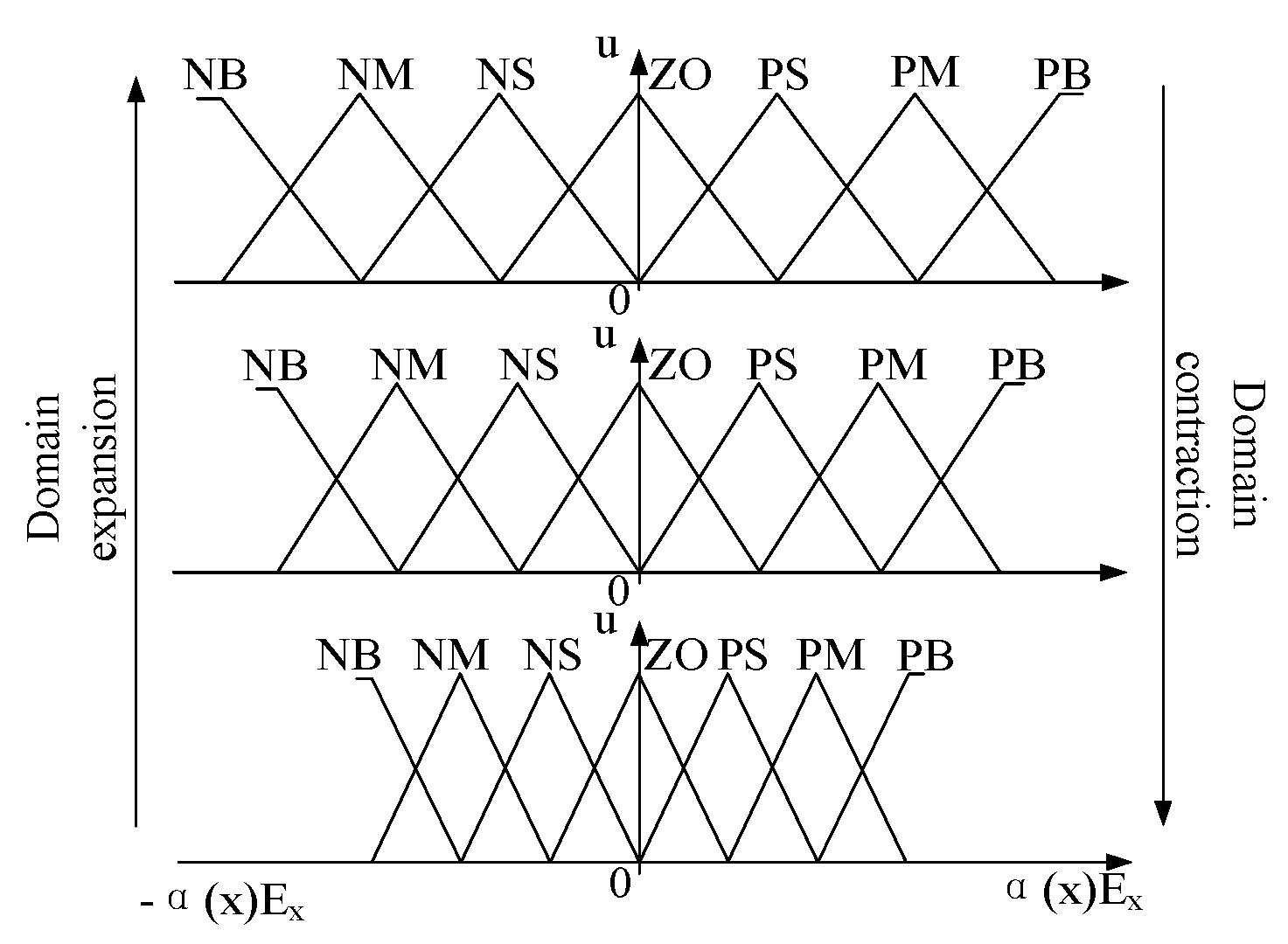
Conventional fuzzy PI control exhibits limited overall system adjustment accuracy and adaptive capability due to fixed fuzzy rules. Variable-domain fuzzy control maintains fixed fuzzy control rules but introduces a scaling factor, α(x), based on the change in x, thereby altering the domain range of x to [−α(x)Ex, α(x)Ex], as illustrated in Figure 6. The domain changes as the error reduces (contracts) or increases (expands). This strengthens control rules, improves control precision, accelerates system convergence, and reduces overshoot. This control method allows real-time parameter adjustment based on system disturbances, providing a superior adaptive adjustment performance.
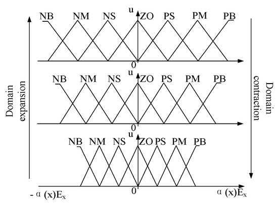
Figure 6.
Expansion and contraction of x’s domain.
4.2. Scaling Factor Design
In variable-domain fuzzy control, the key lies in introducing a scaling factor to adjust the unified fuzzy domain. The range of the domain changes with the scaling factor is in [21,22,23]. Currently, the most common scaling factors are based on functional forms and fuzzy inference forms [14]. The scaling factor related to the input domain is particularly relevant when the input error and error change rate are directly provided by the converter. Therefore, a functional scaling factor is more suitable:
In Equation (11): ; ε is a small positive number close to 0; and E is the boundary value of the input variable error.
Commonly used functional output domain scaling factors are as follows:
where ei(τ) is the input variable error; pi is the input variable weight coefficient; and β(0) is the initial value of the output argument scaling factor.
According to Equation (12), it is evident that the output scaling factor is not only related to e and ec but also to the output of the fuzzy controller. Describing the scaling changes in the output domain using fuzzy language has greater advantages in applications with high-frequency switching loads in power sources compared to calculating scaling factors using functional forms.
Conventional improved fuzzy inference control methods only output a single scaling factor β reasoned from errors and error change rates. Multiplying the output domain of and by the same scaling factor is unreasonable due to the different trends of and with the changes in error e and its change rate . Therefore, a more accurate approach is to formulate scaling factors and separately based on the key load voltage output characteristics for the output domains of and . The design incorporates stretch factors and , aiming to align with changes in both e and simultaneously. The baseline of the load voltage reference value corresponds to the actual values of the error e and its error rate of change . The adjustment of the relationship between the PI parameter change trend is presented in Table 3:
Table 3.
Variation trends of PI parameters.
The fuzzy rule table for outputting the domain scaling factor sums is formulated based on the rules described in Table 4 and Table 5.
Table 4.
Fuzzy rules for .
Table 5.
Fuzzy rules for .
In these tables, VS, S, M, B, and VB represent fuzzy sets for and , which correspond to linguistic values—very small, small, medium, large, and very large.
4.3. Converter System Based on Variable-Domain Fuzzy PI Control
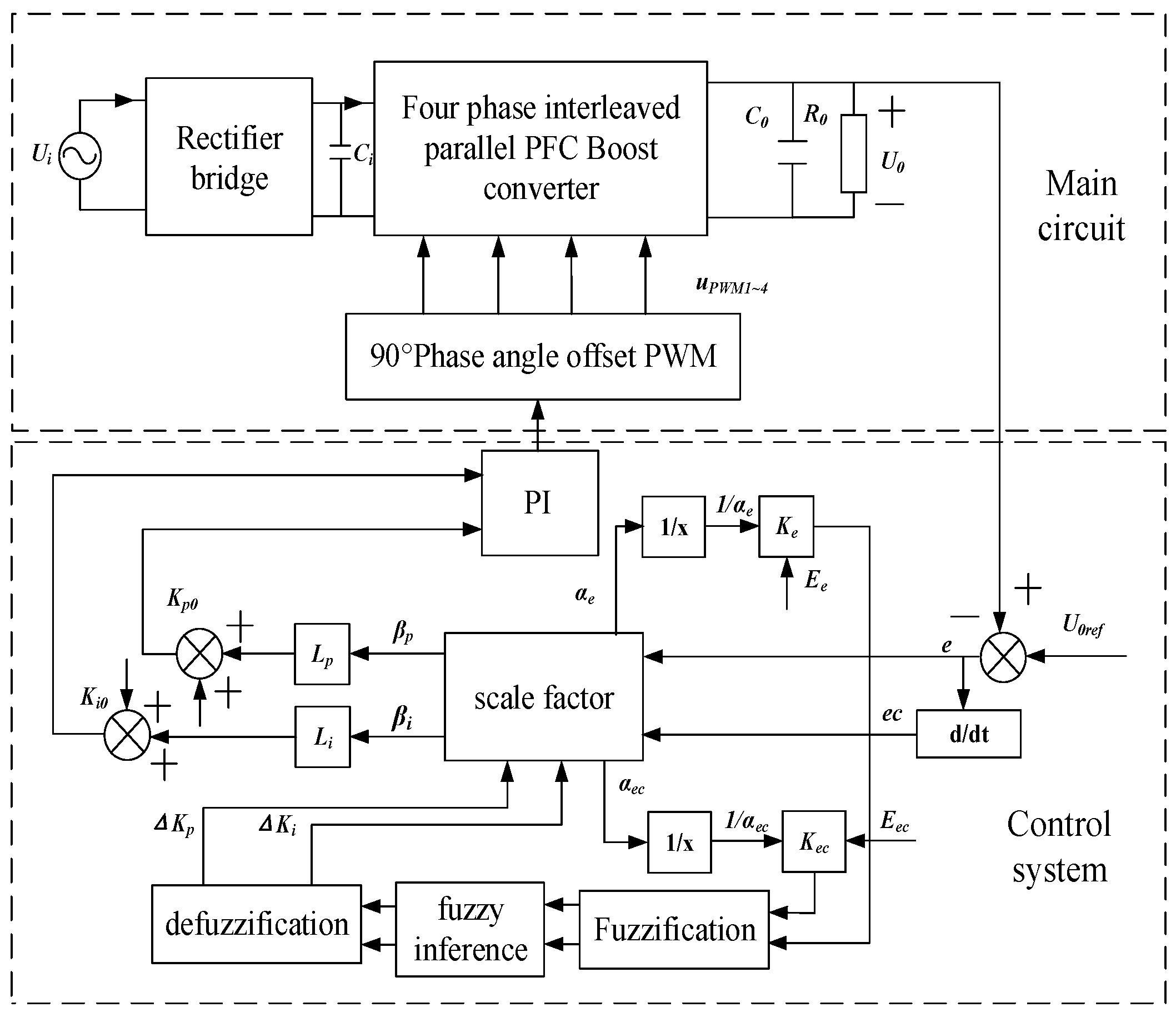
The system structure of the transformer circuit based on variable-domain fuzzy PI control comprises the main circuit and the variable-domain fuzzy PI controller, as illustrated in Figure 7. The implementation of variable-domain fuzzy PI control aims for real-time domain adjustment, achieved by designing the domain change range of e and based on the difference between the output voltage of the transformer and the ideal value. Each point on the input and output domains undergoes point-wise variation by multiplying it with the corresponding scaling factor. To manage the computational load efficiently and ensure simplified calculations with faster output acquisition, an equivalent method for domain transformation is employed.

Figure 7.
System diagram of the four-phase interleaved parallel converter based on variable-domain fuzzy PI control.
With the desired crossing frequency of 5 kHz, the desired value of the phase angle margin of 75° of the expected value of the PI parameter optimization adjustment to obtain the is 0.395 and the is 753.3. Then, the variation range of the fuzzy domain is set as [−6, 6], the variation range of e as [−30, 30], the variation range of as [−300, 300], the variation range of is [−0.1, 0.1], and the variation range of is [−1, 1]. The quantization factors of e and are , (as the unified fuzzy domain boundary values of each variable). If, at this time, e = 30 and = 300, then according to Equation (11), it can be determined that = 5 and = 50, respectively, and , are divided by and , to obtain the input of the fuzzy controller, is 0.04 and 0.0004, respectively. After fuzzification, fuzzy inference, and defuzzification, the clear values of the output quantities and are obtained. According to the proportionality factor, = 1/60 and (for the fuzzy controller output clear value of the change range boundary value; for the change range boundary value), respectively, and multiplied by the clear value of and and the output clear value of and to the parameter with the initial value of and . At this time, the variable theory domain fuzzy PI parameters are obtained, which are used as the compensation amount to adjust the PWM input and control the switching tube turn on and turn off of the four-phase staggered shunt converter, in order to obtain a better dynamic response capability of the converter.
4.4. Simulation Verification
After establishing the control system with the variable-domain fuzzy PI controller as the control core, it is verified by simulation through Matlab.
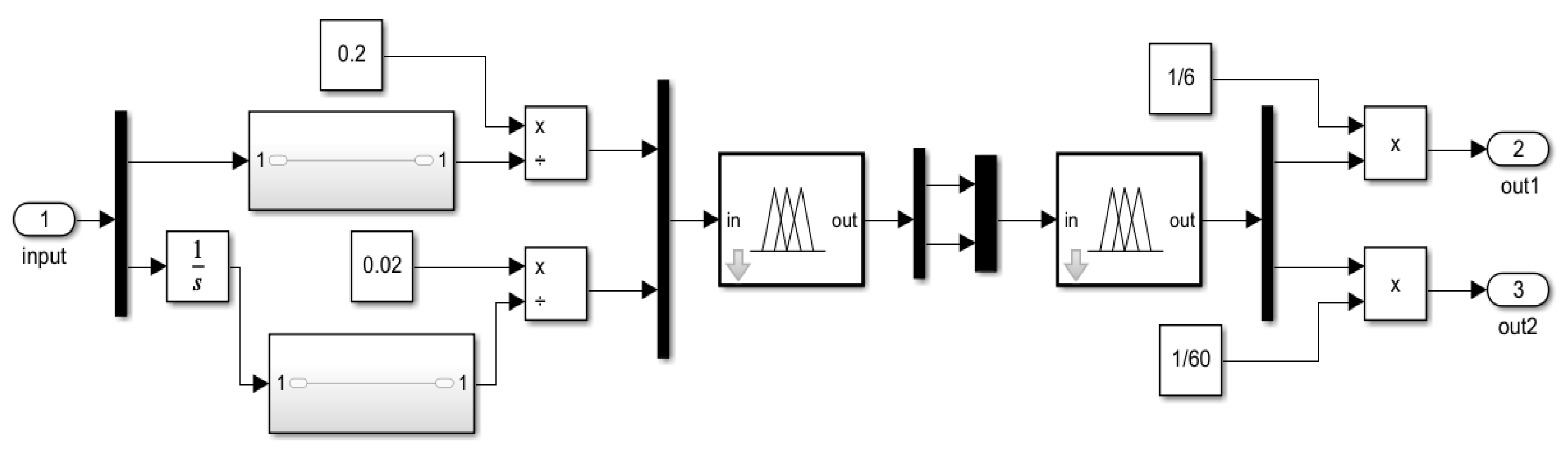
The basic parameters of the designed four-phase interleaved parallel converter are shown in Table 6, and the variable-domain fuzzy controller used in the simulation is illustrated in Figure 8:
Table 6.
Main parameters of simulation model.

Figure 8.
Variable theory domain fuzzy controller model.
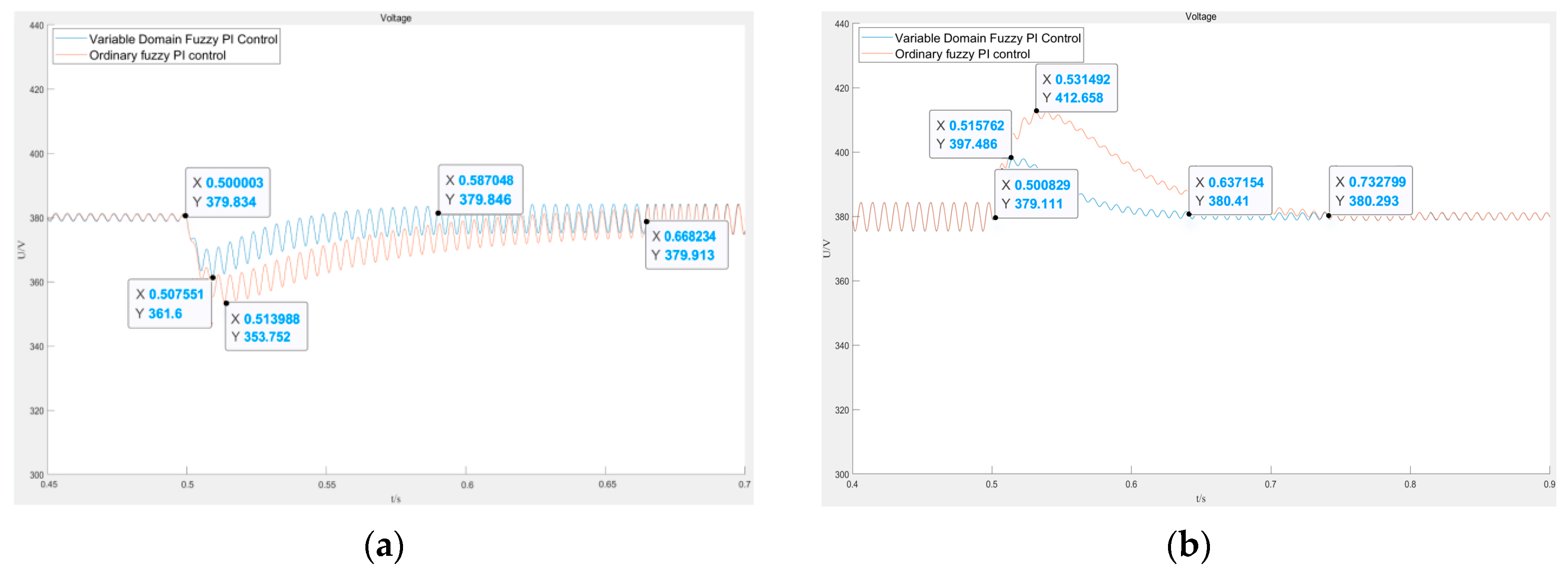
Figure 9a,b show the output voltage waveform of the converter under variable-domain fuzzy PI control and traditional fuzzy PI control, respectively, when switching loads. The simulation results, with a load transition between 25% and 100% occurring at 0.5 s, preliminarily confirm that the converter under variable-domain fuzzy PI control exhibits faster dynamic response and smaller overshoot.
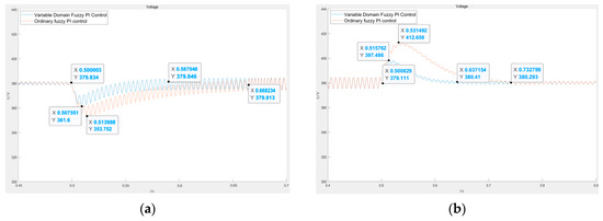
Figure 9.
Output voltage changes when switching loads. (a) 25% load jump to 100% load (b) 100% load jump to 25% load.
5. Experimental Verification
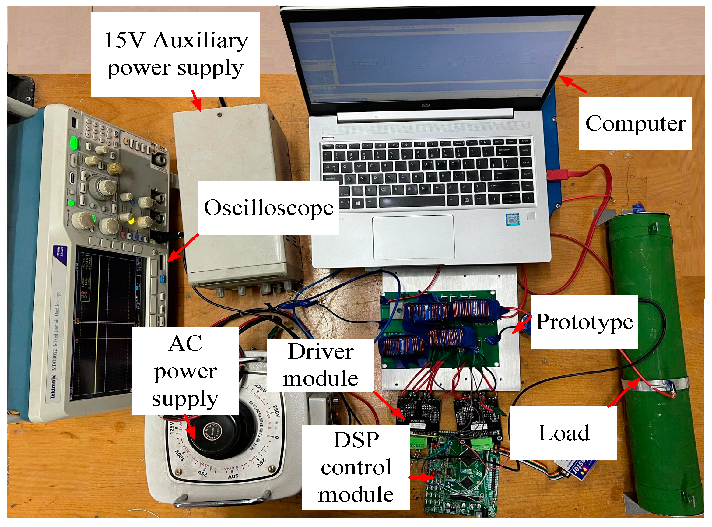
To further validate the superior adaptive capability and better dynamic response of variable-domain fuzzy PI control compared to traditional fuzzy PI control, an experiment is conducted. The designed output power is 1000 W, the output voltage is 380 V, the input voltage is 220 VAC, and the switches used are SiHB33N60EF Mosfets with a withstand voltage of 600 V and a maximum overcurrent of 33 A. The rectifier bridge used is KBPC5010W. The prototype is shown in Figure 10.

Figure 10.
Experimental platforms.
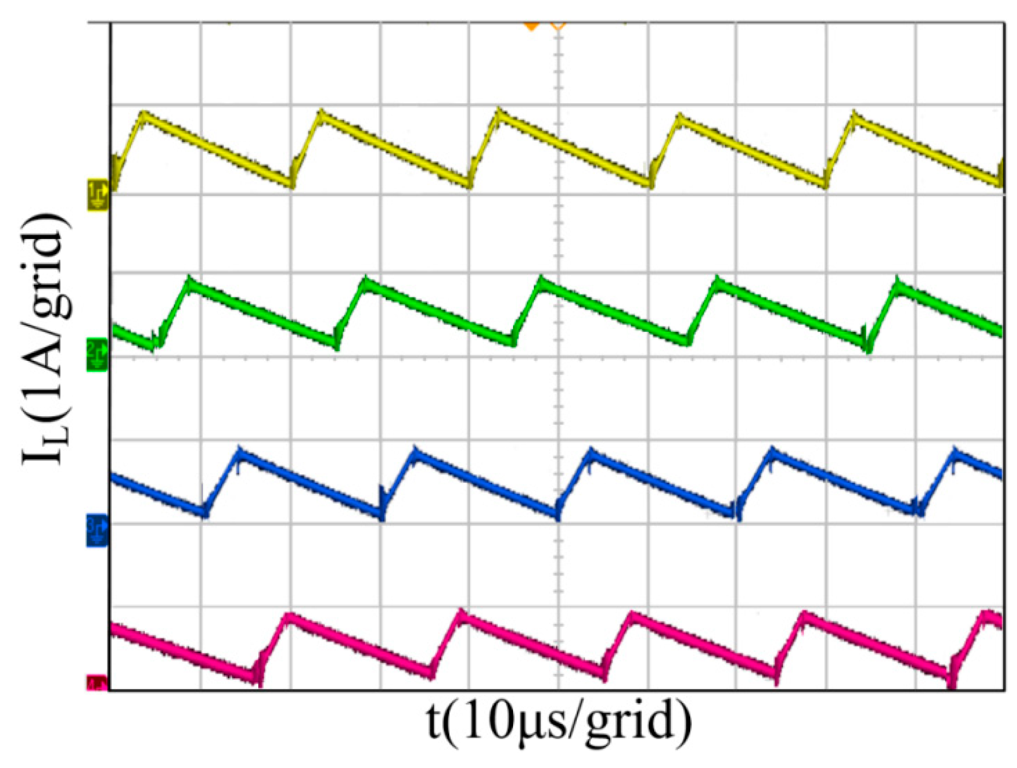
The inductor current waveforms for the four channels of the interleaved parallel converter are shown in Figure 11. The phase differences of the currents for each channel are 90°, and under variable-domain PI fuzzy control, the converter still maintains good current sharing performance.

Figure 11.
Inductor current waveforms for four channels. (The yellow, green, blue, and pink colors represent the inductive current flowing through inductors L1–4, respectively).
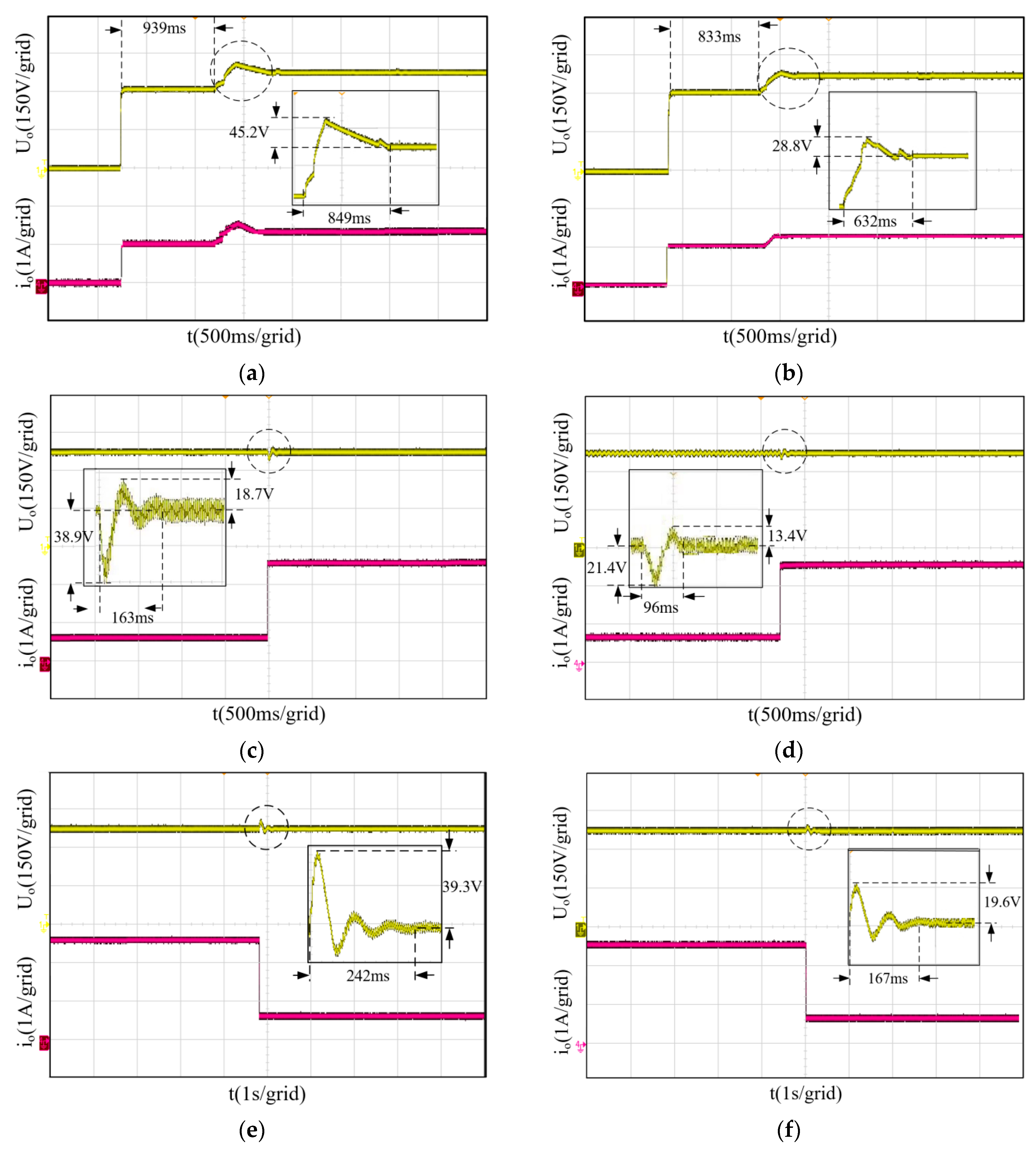
Figure 12a–f show the voltage waveforms of the four-phase interleaved parallel converter under fuzzy PI control and variable-domain fuzzy PI control when the operating states change. Figure 12a,b show waveforms with a zoomed-in horizontal axis of 500 ms/grid and a vertical axis of 50 V/grid. Figure 12c–f show waveforms with a zoomed-in horizontal axis of 100 ms/grid and a vertical axis of 20 V/grid. The time to reach a steady state and the maximum overshoot during state transitions are summarized in Table 7 and Table 8.
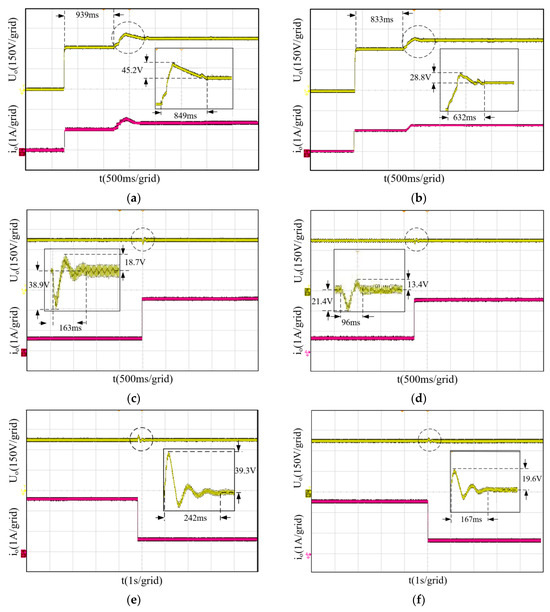
Figure 12.
Output voltage. (The yellow line represents the output voltage and the pink line represents the output current.) (a) Fuzzy PI control-converter startup. (b) Variable-domain fuzzy PI control-converter startup. (c) Fuzzy PI control—25% load jump to full load. (d) Variable-domain fuzzy PI control—25% load jump to full load. (e) Fuzzy PI control—full load jump to 25% load. (f) Variable-domain fuzzy PI control—full load jump to 25% load.
Table 7.
Time for the converter to reach steady state for the two control modes.
Table 8.
Maximum overshoot when the converter operating state is changed in the two control modes.
From Table 7 and Table 8, it can be seen that the time to reach steady state under variable theory domain fuzzy PI control for startup, light load switching to full load, and full load switching to light load is reduced by 25.6%, 41.1%, and 30.9%, respectively, and the maximum overshoot is reduced by 36.3%, 28.3%, and 50.1%, respectively, and the maximum drop in the case of light load switching to heavy load is reduced by 44.9%.
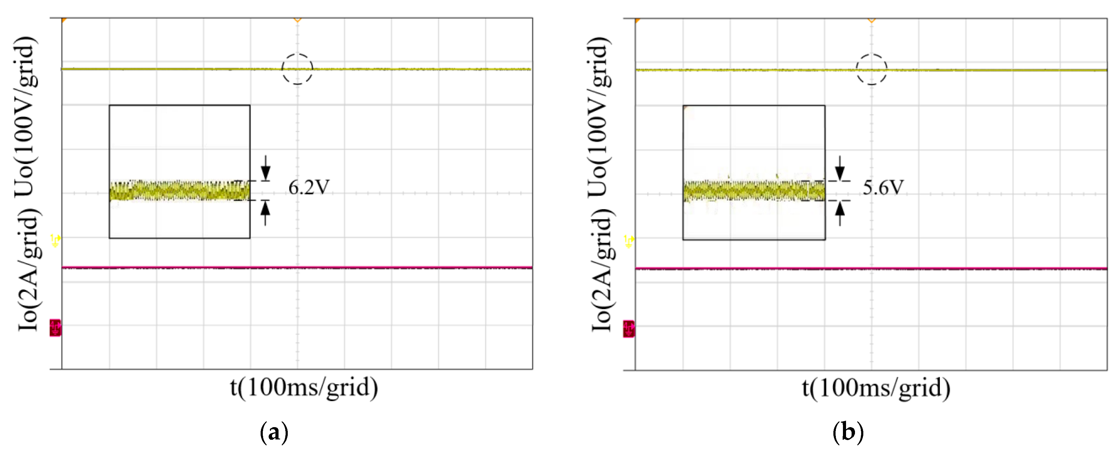
Static stability as another important performance of the converter can also somewhat reflect the control effect of a control method. The output voltage and current waveforms of the fuzzy PI control converter and variable-domain fuzzy PI control converter are shown in Figure 13a,b:

Figure 13.
(The yellow line represents the output voltage and the pink line represents the output current). Output voltage at steady state. (a) Fuzzy PI control converter; (b) variable-domain fuzzy PI control converter.
From Figure 13a,b, it can be determined that the static stability of the converter is better under the two control methods, and the voltage ripple is controlled within 1% of the output voltage, and there is not much difference between the two.
In practical experiments, parasitic parameters of electronic devices affect the results, causing some differences from simulation results, but the disparities are minor. The experimental results further validate the conclusions drawn from the simulation. Additionally, the variable-domain fuzzy PI controller demonstrates better dynamic performance during converter startup and maintains current sharing capabilities.
6. Conclusions
This paper analyzes the shortcomings of conventional control schemes for multi-phase interleaved parallel power converters and proposes a possible control method based on variable-domain fuzzy PI control. This involved method aims to improve the dynamic performance and stability of the converter, while ensuring high voltage gain and power factor output. Based on this approach, a four-phase interleaved parallel converter is designed. Further inquiries including a comprehensive theoretical analysis, simulation analysis, experimental verification, and a comparative study are conducted.
Experimental results demonstrate the effectiveness of the staggered shunt converter boost circuit with a variable-domain fuzzy PI controller. The system exhibits a robust dynamic response during startup and load transitions, with only an 11.9 V overshoot and 21.4 V voltage drop when switching from a 25% load to a 100% load. The system reaches a steady state within 96 ms. Similarly, when transitioning from a 100% load to a 25% load, the overshoot is only 19.6 V, and the system stabilizes after 167 ms. These results substantiate that the proposed scheme adequately meets the power source design requirements of transient electromagnetic systems.
It is important to note that, due to time constraints, the current loop of the dual-loop control system has not undergone control using the variable-domain fuzzy PI control. Further investigation is warranted to assess its efficacy in comparison to the applied control method on the voltage outer loop. Additionally, crucial parameters such as efficiency, input–output range, and others, remain unexplored and should be subjects of future in-depth research.
Author Contributions
Conceptualization, Z.C., W.W. and W.L.; Methodology, Z.C., W.W. and W.L.; Software, Z.C.; Validation, Z.C. and M.L.; Investigation, X.H., W.W. and W.L.; Writing—original draft, Z.C.; Writing—review & editing, Z.F.; Supervision, X.H., W.W., W.L., M.L. and Z.F.; Project administration, Z.F.; Funding acquisition, Z.F. All authors have read and agreed to the published version of the manuscript.
Funding
This work was supported in part by Science and Technology on Near-Surface DetectionLaboratory under Grant 6142414211607, in part by Natural Science Foundation of Chongqing, China Grant CSTB2023NSCQ-MSX0449,in part by the theoretical research on UAV transient electromagnetic method for site selection of mountain power engineering project of science and technology research program of Chongqing Education Commission of China under Grant No. KJQN202301430.
Data Availability Statement
The original contributions presented in the study are included in the article, further inquiries can be directed to the corresponding authors.
Conflicts of Interest
Author W.L. was employed by State Grid Chongqing Electric Power Company. The remaining authors declare that the research was conducted in the absence of any commercial or financial relationships that could be construed as a potential conflict of interest.
References
- Ye, Q.; Zhang, J.; Zhao, Y. Research on the three-dimensional response law of semi aerial transient electromagnetic in tunnel exploration grounding source. J. Basic Sci. Eng. 2021, 29, 1108–1123. [Google Scholar]
- Liu, L.; Li, J.; Liu, J. Design of high-power DC power supply for aviation transient electromagnetic transmitter. Mod. Electron. Technol. 2017, 40, 171–173. [Google Scholar]
- Lu, K.; Fan, Y.; Li, X. A finite-difference offset imaging method for transient electromagnetic transients from electrical sources. Chin. J. Geophys. 2023, 66, 854–869. [Google Scholar]
- Kim, H.; Park, Y.; Son, Y.; Kang, J.; Li, J.; Kim, J. The DC Inductor Current Ripple Reduction Method for a Two-Stage Power Conversion System. Electronics 2023, 12, 3005. [Google Scholar] [CrossRef]
- Boualem, S.; Hassan, E.; Tarek Ahmed, A. Adaptive output feedback control of interlaved parallel boost converters associated with fuel cell. Electr. Power Compon. Syst. 2015, 43, 1141–1158. [Google Scholar]
- Jiang, Q.; Huang, Z.; Cheng, Q. A novel model predictive control strategy for MMC-based PET intermediate isolated stage DC-DC converter. Electr. Power Constr. 2022, 43, 49–57. [Google Scholar]
- Niraj, R.; Subrata, B. Development of an improved input-parallel output-series buck-boost converter and its closed-loop control. IEEE Trans. Ind. Electron. 2020, 67, 6428–6438. [Google Scholar]
- Zhang, Y.; Gong, R.; Liu, J. Fuzzy high-order sliding mode control of three-phase interleaved parallel DC-DC converter. J. Control Theory Appl. 2023, 40, 565–573. [Google Scholar]
- Du, Y.; Wang, J. Research on interleaved parallel bidirectional DC/DC converter based on fuzzy control. J. Electr. Autom. 2018, 50, 88–91. [Google Scholar]
- Yang, H.; Fu, Q.; Wang, B.; Chen, Y.; Su, Y. Communication-Free Interleaving Control of Parallel-Connected DC-DC Converters. Electronics 2023, 12, 2111. [Google Scholar] [CrossRef]
- Li, P.; Zhang, C.; Padmanaban, S.; Zbigniew, L. Multiple modulation strategy of flying capacitor DC/DC converter. Electronics 2019, 8, 774. [Google Scholar] [CrossRef]
- Su, B.; Wang, Y.; Wang, P. Multiphase interleaved parallel bi-directional DC-DC converter based on coupled inductors and its equalization control. Trans. China Electrotech. Soc. 2020, 35, 4336–4349. [Google Scholar]
- Zhang, Z.; Xu, T.; Xiang, L. Multiphase interleaved parallel self-averaging high-gain DC/DC converter and Its control strategy. Electr. Mach. Control 2021, 25, 27–37. [Google Scholar]
- Jiang, W.; Liu, G.; Wang, T. Variable universe fuzzy PID vibration control method based on adaptive scaling factor. Eng. Mech. 2021, 38, 23–32. [Google Scholar]
- Boukhalfa, G.; Belkacem, S.; Chikhi, A. Application of genetic algorithm optimized fuzzy second-order sliding mode control in direct torque control of dual star induction motors. J. Cent. South Univ. 2022, 29, 3974–3985. [Google Scholar] [CrossRef]
- Lv, G.; Xu, W.; Wang, P. Power Spring control strategy based on variable domain fuzzy PI adaptive control. Autom. Electr. Power Syst. 2020, 44, 172–178. [Google Scholar]
- Ma, G.; Xu, G.; Chen, Y. Voltage stability control method of electric springs based on adaptive PI controller. Int. J. Electr. Power Energy Syst. 2018, 95, 202–212. [Google Scholar] [CrossRef]
- Lin, Z.; Wei, Y.; Luo, B.; Liu, X.; Yang, H. A novel control strategy for SVG reactive power compensation based on variable domain fuzzy PI. Power Capacit. React. Power Compens. 2019, 40, 58–62. [Google Scholar]
- Pan, H.; Jin, D. Design and application of variable universe fuzzy controller based on cat swarm optimization. Math. Probl. Eng. 2016, 2016, 4632064. [Google Scholar] [CrossRef]
- Yao, G.; Wang, X.; Wang, Z.; Xiao, Y. Senseless Control of Permanent Magnet Synchronous Motors Based on New Fuzzy Adaptive Sliding Mode Observer. Electronics 2023, 12, 3266. [Google Scholar] [CrossRef]
- Li, X.; Ma, L.; Yuan, C. A study of fuzzy PID vector control with fuzzy scaling factor optimization of variable theory domains. Electr. Power Sci. Eng. 2019, 35, 14–19. [Google Scholar]
- Zhang, K.; Wang, X.; Hua, L. Research on the offset mechanism and adaptive fuzzy control method of radial-axial rolling process of super-large ring parts. Eng. Mech. 2023, 34, 109–117. [Google Scholar]
- Shen, Q.; Wang, C.; Gao, X. A High Spin Missile Attitude Control Algorithm Based on Variable Universe Fuzzy Control. Trans. Beijing Inst. Technol. 2022, 42, 634–640. [Google Scholar]
Disclaimer/Publisher’s Note: The statements, opinions and data contained in all publications are solely those of the individual author(s) and contributor(s) and not of MDPI and/or the editor(s). MDPI and/or the editor(s) disclaim responsibility for any injury to people or property resulting from any ideas, methods, instructions or products referred to in the content. |
© 2024 by the authors. Licensee MDPI, Basel, Switzerland. This article is an open access article distributed under the terms and conditions of the Creative Commons Attribution (CC BY) license (https://creativecommons.org/licenses/by/4.0/).