Abstract
In this paper, we present an active fault-tolerant, vehicle motion control, based on the multi-agent approach for a four-wheel independent steering system. This improves handling stability and active safety of the vehicle in the case of actuator faults. Firstly, an eight-degree-of-freedom four-input vehicle model is established by using the vector transformation method, which takes the four-wheel angle as the input and the yaw rate and the sideslip angle, obtained by the lateral force of a single wheel, as the outputs. Then, we established the topological structure of the four-wheel independent steering subsystems based on graph theory. Aiming at the known fault conditions, an adaptive sliding mode active fault-tolerant control based on the multi-agent four-wheel independent steering system is proposed, in which the unmodeled part of the system is estimated using adaptive methods. For unknown fault conditions, an active fault-tolerant control of the four-wheel independent steering system based on state observer is proposed. An extended state observer with sliding mode surface function as a state variable is designed to estimate actuator faults. Finally, it was demonstrated that the designed state observer and distributed active fault-tolerant control method reduced the impact of actuator failures on vehicle steering and improved the stability of the steering process based on the Lyapunov theory. The hardware in the loop experimental results validate the effectiveness of the proposed novel method.
1. Introduction
The four-wheel independent steering (4WIS) electric vehicles rely on a flexible control strategy of four wheels to ensure good power and handling performance in extreme working conditions. At the same time, the redundant actuator configuration of 4WIS also improves the controller reconstruction capability under fault conditions and the safety of the vehicle during driving [1].
At present, fault-tolerant control mainly includes passive fault-tolerant control and active fault-tolerant control. Passive fault-tolerant control design control systems are based on robust control concepts, without any changes in the controller and system structure, making them insensitive to faults. However, their adaptive ability to fault tolerance is very limited. Active fault-tolerant control is the real-time reconstruction of vehicle models or controllers based on faults. Its advantage is that it can solve complex fault problems and thus is currently the focus of fault-tolerant control research [2]. Zhang et al. [3] proposed a robust control method using virtual control variables to improve vehicle steering stability through control reconfiguration allocation algorithm. Liu et al. [4] transformed the faulty vehicle model into a convex polyhedral linear model and improved the safety of vehicle driving by reconstructing the controller. Zhou et al. [5] proposed a diagnosis method based on the on-board sensor signal and the unscented Kalman filter to realize motor fault diagnosis and reallocate wheel torque, but this used a linear tire model and cannot reflect the change in sideslip angle when the fault is unstable, so this method is limited to multiple working conditions. Jiao [6] achieved fault-tolerant control through the collaborative control strategy of longitudinal and transverse forces, but did not consider the factors of steering effectiveness and modeling uncertainty. Judalet et al. [7] designed an adaptive observer for fault estimation and constructed the behavior of a nominal system through fault-tolerant control based on inverse bond graph modeling. Simulation shows that this method has good performance. The above analysis shows that research on 4WIS fault-tolerant control, at home and abroad, generally does not consider the uncertainty of the vehicle model. Linear quadratic regulator and model predictive control require a large amount of computing power, resulting in high hardware costs. To improve engineering applications, reducing online computational complexity through optimizing algorithm structures and solving processes should also be a research focus.
Multi-agent systems enable several systems with simple intelligence, which are easy to manage and control, to achieve complex intelligence through mutual collaboration, reducing system modeling complexity while improving system robustness, reliability, and flexibility. With the complexity of multi-agent systems, the probability of internal failures in the system greatly increases, and the failure of a single agent may evolve into the failure of the entire system. Therefore, the security and reliability of the multi-agent system is particularly important. Chen et al. [8] compensated for fault effects and uncertainties in the system by designing a fully distributed continuous adaptive fault-tolerant control, enabling multi-agent systems to achieve fault-tolerant consistency. Ye et al. [9] studied a robust fault-tolerant controller designed to achieve stability of the system under actuator faults and unknown global information. Liu [10] estimated disturbances in the system through interference observers and designed an active fault-tolerant controller based on an event-triggering mechanism to save network communication resources. Yang et al. [11] studied the situation of multi-agent systems with disturbances in directed graphs and proposed a distributed control based on disturbance observers. Yang et al. [12] adopts a disturbance observer in second-order multi-agent systems with external disturbances to achieve consistency in both fixed and switched topology structures. Furthermore, Ge et al. [13] proposed an adaptive sliding mode fault-tolerant control strategy for multi-agent systems with actuator faults and external disturbances. The above research mainly considers homogeneous multi-agent systems; however, heterogeneous multi-agent systems have a more widespread existence in practical applications. Zhang et al. [14] proposed a real-time fault-tolerant scheduling algorithm for heterogeneous distributed systems, thereby improving the stability of the system. Zou et al. [15] studied the distributed fault-tolerant consistent tracking control problem for a class of nonlinear multi-agent systems and implemented tracking control using fuzzy logic system approximation technology. Liu et al. [16] studied heterogeneous multi-agent systems and proposed a decentralized output sliding mode fault-tolerant control. The above analysis highlights that current research on 4WIS fault-tolerant control is more focused on hardware redundancy design and complex fault-tolerant control method design. These methods will increase manufacturing costs and real-time computing burdens in practical applications.
The actuator of a 4WIS needs to be started frequently to cope with the time-varying working conditions, and because the mechanical coupling between the subsystems is relatively weak, the actuator fault is more hidden. Therefore, the design of the fault-tolerant control mechanism for 4WIS has important practical significance to improve the driving safety of the vehicle. Multi-agent control allows each agent to be independent; for example, when an actuator fails, other agents can ensure the stable steering of the vehicle through information exchange. In addition, sliding mode control has unique robustness and complete adaptability to matching uncertainty and external disturbances. This paper introduces full vector control and the multi-agent method, and proposes active fault-tolerant control of a 4WIS based on the multi-agent approach to improve the stability of steering control when the actuator faults. In the first part, the mathematical model of a 4WIS stability control is established based on vector transformation. In the second part, according to the communication and hardware connection of each steering subsystem, the topology structure of a 4WIS is established based on the multi-agent and graph theory. In the third part, this paper proposes an adaptive sliding mode active fault-tolerant control for a 4WIS with known actuator faults. In the fourth part, this paper proposes adaptive sliding mode active fault-tolerant control based on a novel fault state observer when actuator fault parameters are unknown. In the fifth part, the proposed method is analyzed by a simulation experiment.
2. Four-Wheel Independent Steering System Model Based on Vector Transformation
2.1. Four-Wheel Independent Steering System Decomposition Based on Vector Transformation
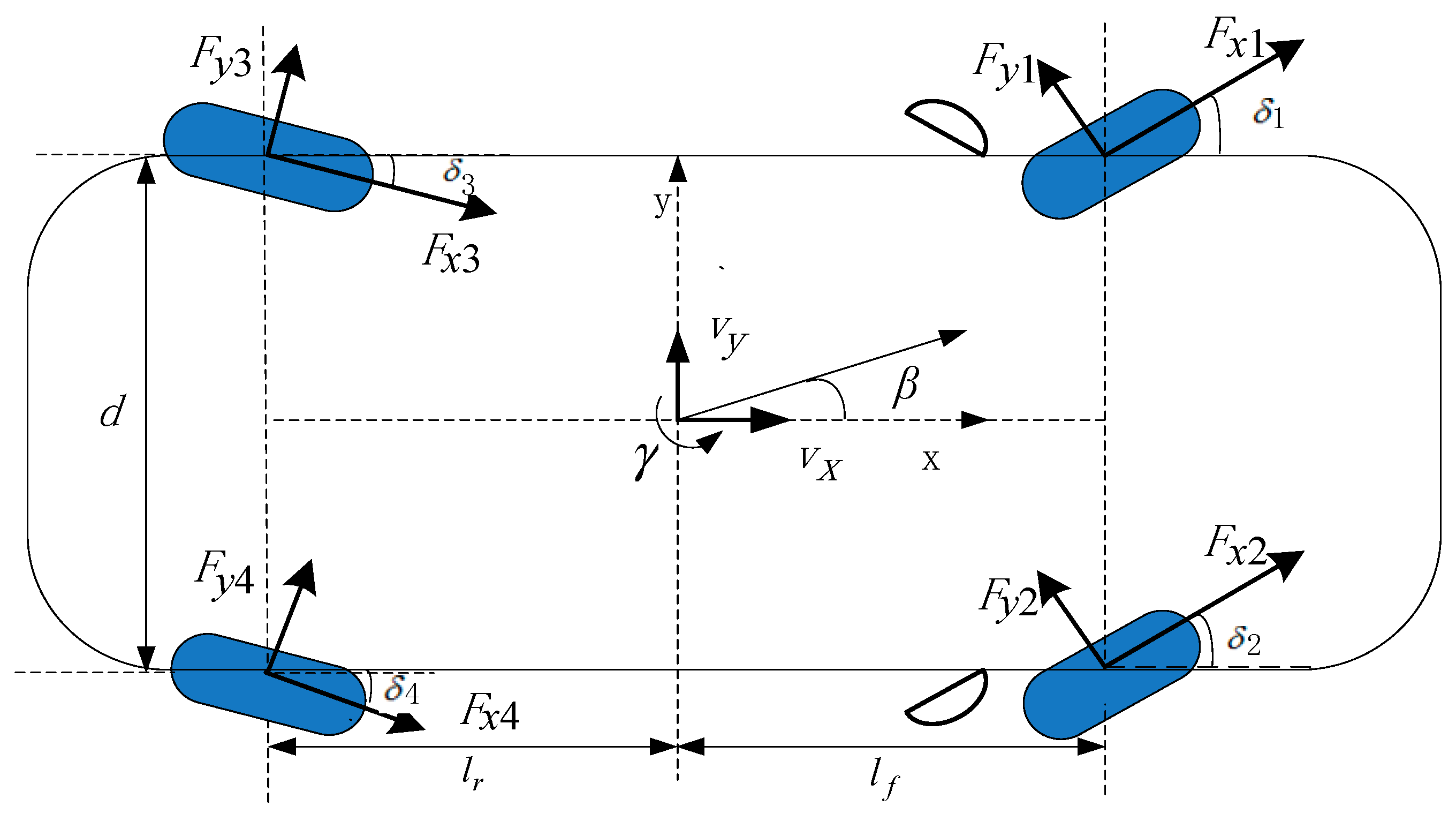
Assuming that the longitudinal and lateral velocities of the vehicle are similar and the sideslip characteristics of the tire are in the linear range, only the lateral, longitudinal, and yaw motions of the vehicle are considered, while the dynamic characteristics of the roll and suspension are ignored after the roll, pitch, and vertical motions are ignored [17,18]; the vehicle dynamic model is shown in Figure 1.

Figure 1.
Vehicle model.
According to Figure 1 and Newton’s Law, the linear two-degree-of-freedom vehicle dynamics equation can be described as follows:
where is the sideslip angle, is the yaw rate, and and are the distances from the front and rear axles to the centroid, respectively. is the i-th wheel lateral force. represents the component of the lateral force of the i-th tire on the y-axis. is the lateral velocity. is the vehicle mass. is the yaw moment of inertia.
The 4WIS can improve the vehicle’s low-speed flexibility and high-speed handling stability, and the direct yaw moment control technology can improve the handling stability under extreme conditions. In this paper, an eight-degree-of-freedom four-input vehicle model is established by vector transformation, which takes the four-wheel angles as the input and the sideslip angle and yaw rate produced by the four-wheel forces acting on the center of the mass alone as the output.
Let and represent the yaw rate and sideslip angle, respectively, at the center of mass of the vehicle when the lateral force of wheel, i, acts alone. The following equations are satisfied: , and .
Moreover, , , , , , , , , , , , and are set.
Therefore, the differential equation of motion (1) of the two-degree-of-freedom (2DOF) model can be rewritten as follows:
Considering the change in the tire steering stiffness, , and residual lateral force, , of tires, the following equation can be obtained:
where is the i-th wheel equivalent sideslip stiffness and is the i-th tire slip angle.
According to the geometric relationship in plane kinematics, the tire slip angle is as follows:
where represents the impact of other steering subsystems on the system and is the i-th wheel steering angle.
Equation (4) is organized as follows:
Let represent the modeling error of the i-th tire force linear model.
By substituting Equation (5) into Equation (3), we can obtain the following:
Then, the state space equation of the single wheel steering system is obtained as follows:
It can be seen that through vector transformation, the 2DOF vehicle dynamics Equation (1) is decomposed into the form of four-wheel independent steering subsystems (7).
2.2. Ideal Four-Wheel Independent Steering Subsystem Model
If the vehicle is regarded as a mass point concentrated at the center of mass, then the trajectory of the center of mass is the trajectory of the vehicle. The change trajectory of the sideslip angle reflects the stability of the vehicle [19,20]. If the sideslip angle tends to an ideal value, that is the vehicle does not slide sideways, the stability will be improved [21,22]. Based on the 2DOF vehicle model of the front wheel steering vehicle, the steering angle is input to the vehicle. After a steady state response, the steering wheel angle and the ideal yaw rate are transformed into first-order inertial links:
where is the ideal yaw rate, is the reference front wheel angle, is the stability factor, is the damping constant of the yaw rate, and and are the lateral stiffness of the front wheel and the rear wheel.
According to Equations (2) and (10), the ideal state equation for a single wheel steering system is established as follows:
When the actual state of the vehicle (7) approaches the ideal state (11), it can effectively improve the steering stability of the vehicle.
Moreover, , , , and are defined. According to Equations (7) and (11), the deviation equation between the yaw rate and the sideslip angle with their ideal value of the i-th wheel steering system can be obtained as follows:
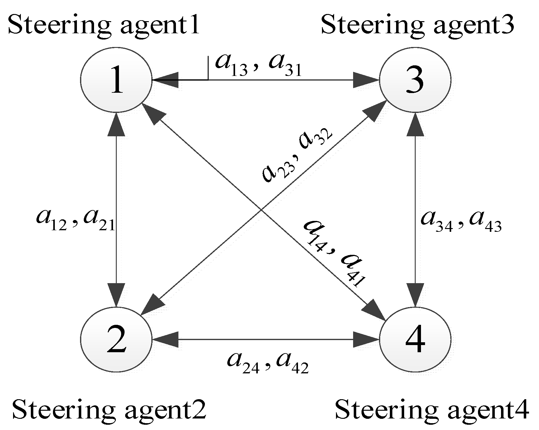
3. Topological Structure of Four-Wheel Independent Steering System Based on Graph Theory
Based on the hardware connection structure and internal working communication of 4WIS, the deviation Equation (12) of the yaw rate, sideslip angle, and expected value of each wheel steering system is regarded as an independent steering agent. Therefore, a topological structure connecting four steering agents can be obtained. Due to the different models of each agent, the 4WIS belongs to a heterogeneous multi-agent system.
A multi-agent system consisting of 4WIS can use a directed/undirected graph to describe the exchange of information with external systems. When any two nodes on the graph are connected, it is called a connected graph; the graph is defined as , where is the non-empty subset associated with N multi-agents and is the set boundary of the multi-agent. If , Node can be used to obtain information from Node , where Node is a neighbor node of Node . The weighted adjacency matrix is defined as when , . The degree matrix of a node is defined as , where . The Laplace matrix is defined as , where .
According to the topology of 4WIS established in Figure 2, the following can be obtained:

Figure 2.
Topology of the 4WIS.
The deviation Equation (12) between the ideal state and the actual state of the i-th steering agent is taken as the agent. The steering control strategy of the i-th steering agent is proposed by considering the influence of other wheel agents so that the yaw rate and sideslip angle can quickly track the ideal value.
4. Active Fault-Tolerant Control of Four-Wheel Independent Steering System Based on Multi-Agent
4.1. Adaptive Sliding Mode Active Fault-Tolerant Control for Four-Wheel Steering Systems with Known Actuator Faults
Consider three typical types of faults in the actuator of a four-wheel independent steering system, namely gain change fault, constant deviation fault, and stuck fault. The outputs of different types of faulty actuators are uniformly described using the following formula:
where is the degree of actuator failure, is the degree of actuator paranoia fault, and is the normal output of the actuator. According to the fault characteristics of the actuator, the following holds true: normal state: ; gain change fault: , ; constant deviation fault: ; stuck fault: .
Let , , , , then Equation (12) can be organized as follows:
Let be the pseudo inverse matrix of ; the following is then satisfied: . Design the pseudo inverse matrix as follows:
By multiplying the left and right sides of Equation (15) by , we can obtain the following:
Let , and select nonsingular terminal sliding mode surface as follows:
where and are odd numbers, and .
Then, the nonsingular terminal sliding mode control strategy is designed as follows:
where , is the estimated value of , and it satisfies the following:
Theorem 1.
For the 4WIS with known actuator faults, the nonsingular terminal sliding mode surface (18), the nonsingular terminal sliding mode control strategy (19), and the adaptive rate of change (20) of the i-th steering agent are designed so that the actual yaw rate and sideslip angle of the vehicle can quickly follow the ideal value.
Proof.
Select the Lyapunov function as follows:
where .
Taking the derivative of the nonsingular terminal sliding mode surface function (18) yields the following:
Taking the derivative of Lyapunov function (21) and incorporating the adaptive rate of change (22) of and sliding mode control strategy (19), we can obtain the following:
Let and . By incorporating the adaptive rate of change (20) of into Equation (23), we can obtain the following:
According to the Lyapunov stability theorem, when the system state reaches the sliding mode surface, the following can be obtained: , , , , , , . Thus, the actual yaw rate and sideslip angle can quickly follow their ideal values. □
4.2. Stability Analysis
From , can be obtained, then
By substituting the Equation (12), we can obtain the following:
From the vehicle model, we can obtain the following:
According to Equations (26) and (27), when , there is , and can be obtained from Equation (25).
Therefore, by designing the sliding surface function (18), control strategy (19), and adaptive estimation (20) of rate of change , it is possible to quickly follow the ideal sideslip angle and yaw rate.
5. Adaptive Sliding Mode Active Fault-Tolerant Control for 4WIS Based on a Novel Fault State Observer
When the actuator fault parameters, and , are unknown, in order to separate the fault item, the fault actuator output (14) is transformed as follows:
If is an actuator failure coefficient, then
Equation (17) can be reorganized as follows:
Design a nonsingular terminal sliding mode control strategy as follows:
where design parameters meet , is the estimated value of and satisfies the following:
A sliding mode extended state observer with sliding surface function as the observer state variable is proposed for the actuator failure coefficient .
Taking the derivative of the nonsingular terminal sliding surface function (18) and incorporating Equation (17), we can obtain the following:
Define and as the estimates of and , respectively. , . Design a sliding mode extended state observer based on sliding surface function to observe the actuator failure coefficient .
Assuming that the unknown actuator fault is a slow time-varying signal, and , the error equation of the observer can be obtained:
where , .
Theorem 2.
For a 4WIS with unknown actuator faults, a nonsingular terminal sliding mode surface (18), a nonsingular terminal sliding mode control strategy (30), an adaptive rate of change of uncertainty (31), and a constraint condition (38) for the i-th steering agent are designed to achieve rapid tracking of the actual yaw rate and sideslip angle to their ideal values.
Proof.
Select the Lyapunov function as follows:
where , , .
Taking the derivative of Equation (20) and incorporating Equations (31), (32) and (34) into (35), we can obtain the following:
By incorporating the control strategy (30) in the case of actuator fault location into (36), we can obtain the following:
Select , , , , , , and the following is satisfied:
Then,
where , , .
According to the Lyapunov stability theorem, when the degree of actuator failure and the degree of actuator paranoia fault are unknown, the system state reaches the sliding mode surface, and the following can be obtained: , , , , , . Thus, it is possible to observe actuator faults and quickly follow the ideal values of the yaw rate and the sideslip angle under actuator faults. □
6. Simulation Experiment
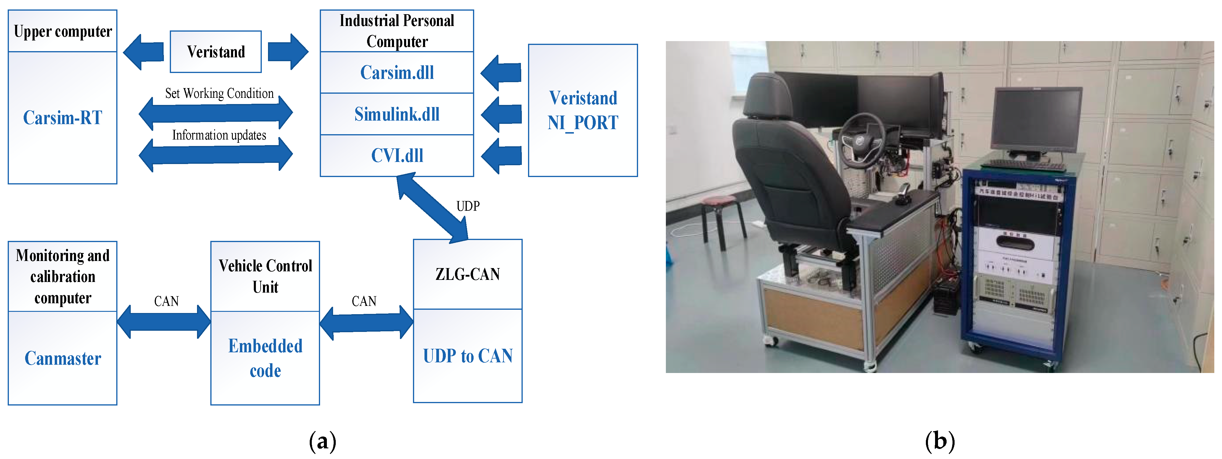
In this paper, a hardware in the loop testing experimental platform for vehicle controllers is built based on the Veris and RT and CarSim-RT platforms. The platform mainly includes upper computer, lower computer, CAN card, embedded onboard vehicle controller, and monitoring and calibration computer. This platform utilizes a hardware-embedded platform to replace the mathematical model environment in Simulink and can test the feasibility of algorithm transplantation to actual vehicles. The structure of the experimental platform is shown in Figure 3a. The experimental platform is shown in Figure 3b.

Figure 3.
(a) The structure of the experimental platform; (b) the experimental platform.
In order to verify the control effectiveness of the fault-tolerant control method proposed in this paper with actuator failure, dynamic simulation is conducted by the step input test with known actuator faults and the continuous sine test with an unknown actuator failure, and compared with PID control vehicles and FWS vehicles. The simulation vehicle parameters are shown in Table 1.

Table 1.
Vehicle parameters.
6.1. Step Input Test with Known Actuator Faults
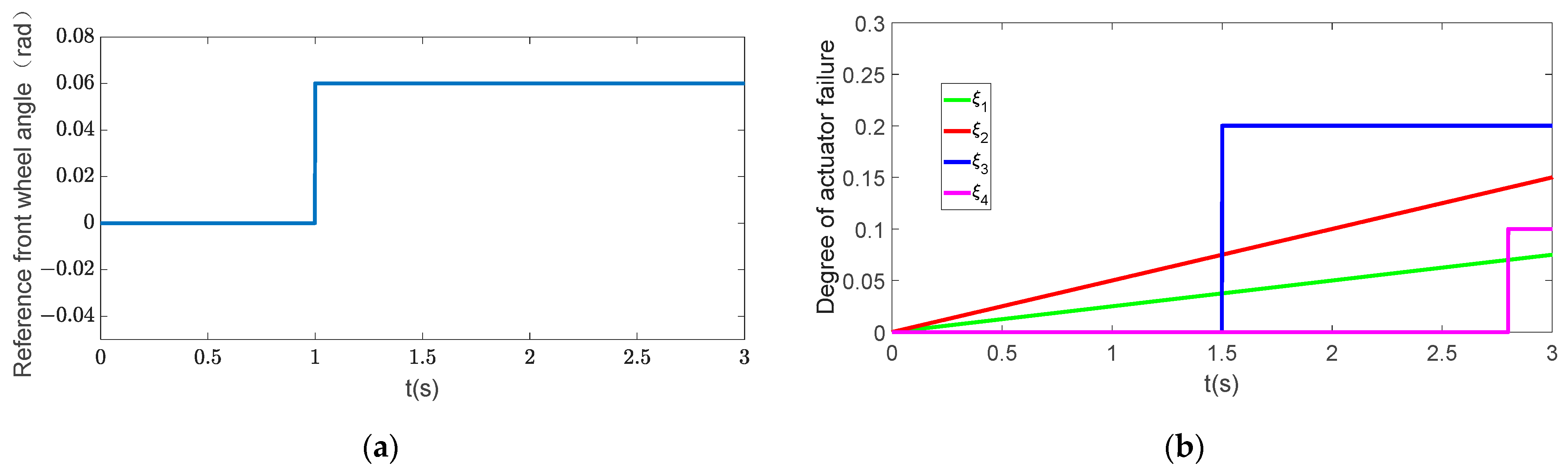
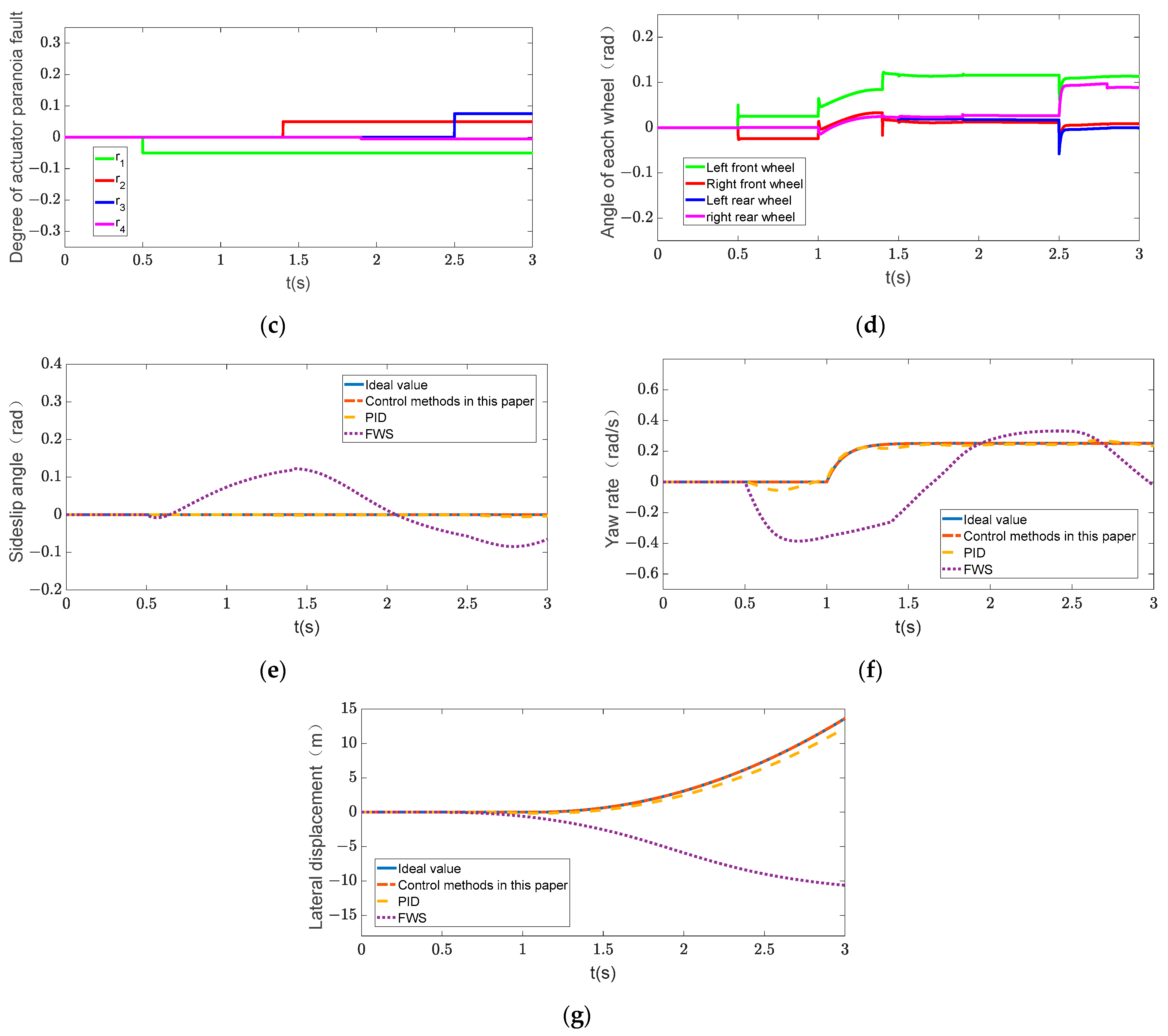
The step input test is an important index that measures the vehicle handling stability, which is mainly used to analyze whether the vehicle can reach a steady state when the angle step input is provided and whether the steady state value is realistic. When the actuator malfunction is known, the simulation working condition is set as follows: The reference front wheel angle changes as shown in Figure 4a; the jump time is 1 s, and the total simulation time is 3 s. The degree of actuator failure and degree of actuator paranoia fault are shown in Figure 4b,c. At 1 s, the wheels enter a non-zero steady state after transient response, and the change in the angles of each wheel as the actuator malfunctions are shown in Figure 4d.


Figure 4.
Step input test. (a) Reference front wheel angle; (b) degree of actuator failure; (c) degree of actuator paranoia fault; (d) angle of each wheel; (e) sideslip angle; (f) yaw rate; (g) lateral displacement.
From Figure 4e,f, it can be seen that when the left front wheel fails at 0.5 s, the sideslip angle and yaw rate of the FWS vehicle begin to deviate from the ideal value, indicating that the vehicle is in an unstable state during the steering process. The actuator of the vehicle under PID control fails at 0.5 s; the yaw rate also deviates from the ideal value, and it returns to the ideal value after 0.3 s of adjustment. Later, when the actuator fails, the yaw rate also deviates from the ideal value and return to the ideal value after adjustment. The fault-tolerant control in this paper can ensure that the sideslip angle and yaw rate stably follow the ideal values after actuator failure, providing the vehicle with good steering characteristics. From Figure 4g, it can be seen that as the actuator failure of the vehicle intensifies, the lateral displacement of the FWS vehicle gradually deviates from the ideal value. The lateral displacement of the vehicle under PID control also deviates from the ideal value, and there is a deviation of 0.8 m from the ideal value at 3 s. The fault-tolerant control method can ensure that the vehicle always maintains the ideal trajectory during the steering process, demonstrating the ideal steering effect, indicating that the fault-tolerant control can effectively compensate for actuator failures.
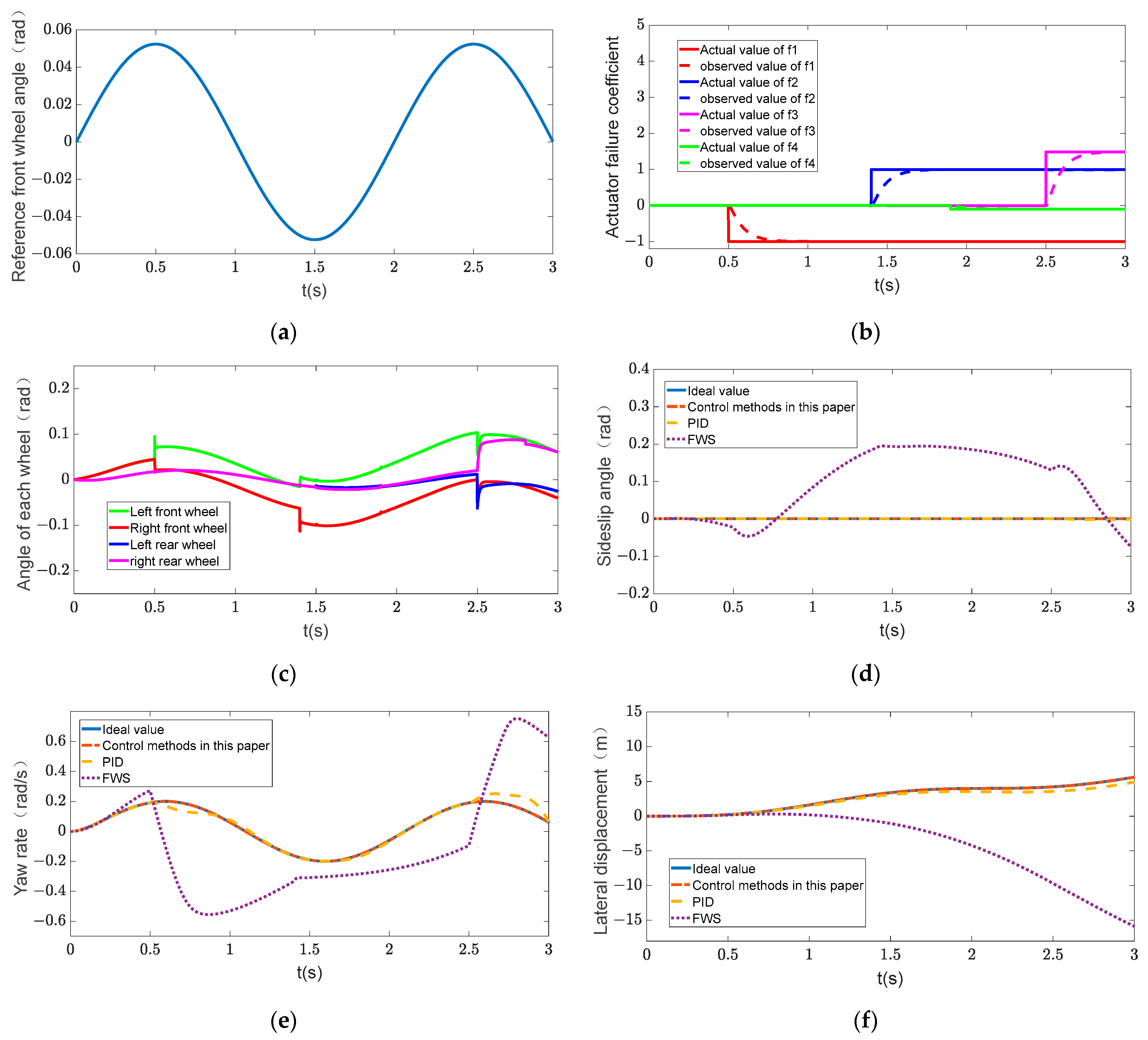
6.2. Continuous Sine Test with Unknown Actuator Failure
The continuous sine test stimulates the dynamic characteristics of the vehicle by continuously moving the line to objectively evaluate the handling stability and safety of the vehicle. In the case of unknown actuator fault parameters, the simulation condition is set as follows: The reference front wheel angle changes as shown in Figure 5a. The actual and observed values of the actuator failure coefficient are shown in Figure 5b; it can be seen that the observer designed in this paper can achieve estimation of the actuator failure coefficient. The changes in the four-wheel angles are shown in Figure 5c.

Figure 5.
Continuous sine test. (a) Reference front wheel angle; (b) actuator failure coefficient; (c) angle of each wheel; (d) sideslip angle; (e) yaw rate; (f) lateral displacement.
Figure 5d,e indicate that as actuator failures worsen, the fault-tolerant control method proposed in this paper can ensure that the sideslip angle and yaw rate can follow the ideal values, reflecting that the fault-tolerant control method is conducive to the safe driving of the vehicle after actuator failures and does not cause sudden loss of control and misoperations. The yaw rate and sideslip angle of FWS vehicles deviate from ideal values with the occurrence of actuator faults and experience significant fluctuations as the degree of the fault intensifies, indicating that the vehicle gradually loses stability during continuous steering. At 0.5 s, 1.4 s, and 2.5 s, when the actuator fails with the vehicle under PID control, it can be seen that the yaw rate deviates from the ideal value. Although the yaw rate is adjusted back to the ideal value, the driving experience is also affected in this process. Figure 5f shows that the fault-tolerant control method can enable vehicles to complete continuous gear shifting tasks with high accuracy. The lateral displacement of FWS vehicles gradually deviates from the ideal value, indicating that the vehicle deviates from the predetermined turning track. Due to actuator failure, the lateral displacement of vehicle under PID control deviated from the ideal value by 0.7 m at 3 s. The above indicates that fault-tolerant control has good performance, which can improve the system’s fault-tolerant ability in time-varying failure faults and significantly improve the safety of the system in the event of complex faults.
7. Conclusions
This paper proposed an active fault-tolerant control based on the multi-agent for the 4WIS actuator faults. Firstly, an eight-degree-of-freedom four-input vehicle model is established by using the vector transformation method, which takes the four-wheel angle as input and the yaw rate and the sideslip angle obtained by the lateral force of a single wheel as output. Then, this paper established the topological structure of 4WIS based on the graph theory. Aiming at the known fault conditions, an adaptive sliding mode active fault-tolerant control based on the multi-agent approach is proposed, in which the unmodeled part of the system is estimated using adaptive methods. For unknown fault conditions, an active fault-tolerant control of 4WIS based on state observer is proposed. The simulation results show that the fault-tolerant control proposed in this paper can ensure that the vehicle can track the ideal yaw rate and sideslip angle, and has good reliability and fault-tolerant ability for actuator failure faults, improving the safety of the vehicle during the steering process. The proposed method only considers that the lateral acceleration is less than 0.4 g and the tire side stiffness is in the linear range. In addition, only the gain change fault, constant deviation fault, and stuck fault of the actuator are considered in this paper. Next, research on fault-tolerant control methods for actuator faults in four-wheel independent steering systems under all working conditions and actual vehicle verification will be carried out.
Author Contributions
Conceptualization, H.L.; methodology, H.L.; software, G.W.; validation, Z.L.; formal analysis, H.L.; writing—original draft, H.L.; supervision, H.D.; project administration, C.J.; funding acquisition, N.Z. All authors have read and agreed to the published version of the manuscript.
Funding
This research was funded by National Natural Science Joint Fund Project U1864206, Open Fund of State Key Laboratory of Automobile Simulation and Control of Jilin University 20210237 and Jilin Province Science and Technology Development Plan Project 20230508049RC.
Data Availability Statement
Data are contained within the article.
Conflicts of Interest
Haolin Li was employed by State Grid Baishan Power Supply Company. The remaining authors declare that the research was conducted in the absence of any commercial or financial relationships that could be construed as a potential conflict of interest.
References
- Li, Y.; Xu, X.; Sun, X.D.; Jiang, H.B.; Qu, Y.P. Review and future development of in-wheel motor drive technology. Electr. Mach. Control Appl. 2017, 44, 1–7, 18. [Google Scholar]
- Zhang, L.; Yu, W.; Wang, Z.P. Fault Tolerant Control Based on Multi-methods Switching for Four wheel independently actuated Electric Vehicles. J. Mech. Eng. 2020, 56, 227–239. [Google Scholar]
- Zhang, G.; Zhang, H.; Huang, X.; Wang, J.; Yu, H.; Graaf, R. Active Fault-Tolerant Control for Electric Vehicles With Independently Driven Rear In-Wheel Motors Against Certain Actuator Faults. IEEE Trans. Control Syst. Technol. 2016, 24, 1557–1572. [Google Scholar] [CrossRef]
- Liu, G.H.; Chen, X.F.; Zhang, D. Fault-tolerant control of four-wheel independently driven electric vehicles based on LPV gain-scheduling technique. Mach. Des. Manuf. Eng. 2018, 47, 60–65. [Google Scholar]
- Zhou, H.L.; Jia, F.J.; Liu, Z.Y.; Liu, H.F. Fault Diagnosis and Fault-tolerant control method for In wheel motor electric vehicles. J. Mech. Eng. 2019, 55, 174–182. [Google Scholar]
- Jiao, G.Y. Research on the Coordination and Fault Tolerant Control of Longitudinal and Transverse Forces in Four-Wheel-Independent Drive/Steering Electric Vehicles. Master’s Thesis, Chongqing University, Chongqing, China, 2018. [Google Scholar]
- Judalet, V.; Glaser, S.; Gruyer, D.; Mammar, S. IMM-based sensor fault detection and identification for a drive-by-wire vehicle. IFAC-Pap. 2015, 48, 1158–1164. [Google Scholar] [CrossRef]
- Chen, S.; Ho, D.W.; Li, L.; Liu, M. Fault-tolerant consensus of multi-agent system with distributed adaptive protocol. IEEE Trans. Cybern. 2017, 45, 2142–2155. [Google Scholar] [CrossRef]
- Ye, D.; Zhang, T.Y.; Li, K. Multi agent adaptive fault-tolerant containment control with unknown global information. J. Shandong Univ. Eng. Ed. 2017, 45, 1–6, 11–13. [Google Scholar]
- Liu, Y.S.; Yang, H.Y.; Liu, F.; Li, Y.L.; Yang, Y.Z. Interference active control of multi-agent system consensms under event triggering. Control Theory Appl. 2020, 37, 969–977. [Google Scholar]
- Yang, D.Y.; Mei, J. Consensus of linear multi-agent systems based on distmrbance observer in digraph. Autorrcatica 2018, 44, 1037–1044. [Google Scholar]
- Yang, H.; Zhang, Z.; Zhang, S. Consensus of second-order multi-agent systems with exogenous disturbances. Int. J. Robust Nonlinear Control 2011, 21, 945–956. [Google Scholar] [CrossRef]
- Ge, Z.W.; Liu, J.W.; Wang, Y.F. Fault-tolerant and consensus control algorithm for multi-agent systems based on adaptive sliding mode. Control. Inforrrcat. Technol. 2020, 5, 1–6. [Google Scholar]
- Zhang, K.L.; Cain, X.; Han, Z.F.; Pang, L.P. Research on faulttolerant scheduling model in Heterogeneous distributed real-time system. J. Huazhong Univ. Sci. Technol. 2000, 28, 17–18. [Google Scholar]
- Zou, W.; Ahn, C.K.; Xiang, Z. Fzzy-approximation-based distributed fault-tolerant consensus for heterogeneous switched nonlinear multiagent systems. IEEE Trans. Fuzzy Systerrcs 2020, 29, 2916–2925. [Google Scholar] [CrossRef]
- Liu, C.; Jiang, B.; Patton, R.J.; Zhang, K. Decentralized output sliding-mode fault-tolerant control for heterogeneous multiagent systems. IEEE Trans. Cybern. 2019, 50, 4934–4945. [Google Scholar] [CrossRef]
- Baffet, G.; Charara, A.; Lechner, D. Estimation of vehicle sideslip, tire force and wheel cornering stiffness. Control Eng. Pract. 2009, 17, 1255–1264. [Google Scholar] [CrossRef]
- Zhu, H.J.; Li, L.; Jin, M.J.; Song, J. Real-time yaw rate prediction based on a non-linear model and feedback compensation for vehicle dynamics control. Proc. Inst. Mech. Eng. D J. Automob. Eng. 2013, 227, 1431–1445. [Google Scholar] [CrossRef]
- Leung, K.T.; Whildborne, J.F.; Purdy, D.; Barber, P. Road vehicle state estimation using low-cost GPS/INS. Mech. Syst. Signal Process. 2011, 25, 1988–2004. [Google Scholar] [CrossRef]
- Piyabongkam, D.; Rajamani, R.; Grogg, J.A.; Lew, J.Y. Development and experimental evaluation of a slip angle estimator for vehicle stability control. IEEE Trans. Control Syst. Technol. 2009, 17, 78–88. [Google Scholar] [CrossRef]
- Li, X.; Song, X.; Chan, C. Reliablevehicle sideslip anglefusion estimation usinglow-costsensors. Measurement 2014, 51, 241–258. [Google Scholar] [CrossRef]
- Jin, X.; Yin, G. Estimation of lateral tyre–road forces and sideslip angle for electric vehicles using interacting multiple model filter approach. J. Frankl. Inst. 2015, 352, 686–707. [Google Scholar] [CrossRef]
Disclaimer/Publisher’s Note: The statements, opinions and data contained in all publications are solely those of the individual author(s) and contributor(s) and not of MDPI and/or the editor(s). MDPI and/or the editor(s) disclaim responsibility for any injury to people or property resulting from any ideas, methods, instructions or products referred to in the content. |
© 2024 by the authors. Licensee MDPI, Basel, Switzerland. This article is an open access article distributed under the terms and conditions of the Creative Commons Attribution (CC BY) license (https://creativecommons.org/licenses/by/4.0/).