Abstract
Over the past few years, the Internet of Things paradigm has brought renewed significant interest to indoor positioning, tracking, and localization topics, principally since real-time locating technology allows a reference node to infer the position of tagged target nodes, creating the opportunity for millions of object-to-object awareness applications. This study first presents an overview of positioning localization techniques and discusses the use of ultra-wide bandwidth technology for complex environment monitoring, followed by consideration of the error sources that are present in line-of-sight (LOS) and non-line-of-sight (NLOS) scenarios between a reader and a tag. A technical review of the available industrial and commercial UWB real-time locating transceivers (RTLSs) is presented, with a focus on the frontend antennas that are integrated in these systems to establish the needed wireless communication for positioning. Then, the different characteristics of these antennas are summarized and discussed, along with their impact on the localization performance in terms of the reading range, position information accuracy, object-orientation-independent localization, and multipath mitigation. Solutions are suggested to achieve antenna-based improvements to the performance of RTLSs.
1. Introduction
Research concerning the positioning and localization field has soared in popularity since the 1970s when the US Department of Defense (DoD) decided to design and launch a positioning service with global coverage and continuous-time availability, the Global Positioning System (GPS) [1]. This was first limited to military use only and was then, a decade later, expanded for civil users. This popularity is particularly related to space-based positioning performed by global navigation satellite systems (GNSSs), such as GPS, Galileo, Glonass, and BeiDou, involving a constellation of satellites fixed on Earth-centered orbital planes. However, satellites perform poorly when position information is sought in harsh environment areas for propagation, typically indoor situations (e.g., inside buildings, mines, etc.), where multipath signals reflected from objects and obstacles obscure localization of the desired signal. To provide reliable positioning indoors, many terrestrial-based wireless communication systems have been explored and equipped to perform indoor localization [2]. These include localization through WiFi and Bluetooth technologies [3], which are widely available nowadays in almost any connected mobile device [4,5], or through radio frequency identification (RFID) [6] by subtly adjusting its architecture so that the position information of an object, in addition to its identification [7], can be provided. However, as these technologies were not initially designed to specifically provide localization services, most of them tend to be limited in important respects, such as accuracy, space coverage, and the reading range at which objects can still be detected. To tackle these issues, ultrawide bandwidth (UWB) technology was introduced in radio transceivers [8] and evolved with IEEE standards [9,10]. These were then referred to as real-time locating systems (RTLSs), which are able to achieve consistent centimeter-level accuracy in the positioning of objects indoors because of their high level of robustness against parasitic multipath components [11].
RTLSs performing time-based localization with UWB technology have subsequently been deployed in many applications, such as the monitoring of equipment and staff in healthcare [12,13,14], monitoring of vehicles [15,16] and secure access with UWB-based car keys [17], monitoring in underground mines [18,19,20], monitoring in robotics [21], monitoring of long-range wide area network (LoRaWAN) sensors [22], and the monitoring of athletic performance data in sports [23,24,25].
Although UWB technology has the benefits of fine temporal resolution characteristics, there are challenges in deploying this technology in locating systems. These challenges can be divided into two categories. The first is that UWB is still considered a growing technology compared to its counterparts WiFi and Bluetooth, which are considered standard technologies and are now present in most wireless communication systems. This means that deploying UWB architectures usually involves more effort, tends to be more costly, and the UWB radio solutions generated by different manufacturers are not interoperable. Second, the challenge in localization consists in the fact that, although measurements of time-of-light UWB signals yield precise location estimates, this precision is still prone to error arising from sources that are exterior to the system itself. These error sources are due to the environment in which the reader and tags are placed—the more complex this environment is, the more multipath reflections can obscure the desired signals. Moreover, the multipath problem is present even in line-of-sight (LOS) scenarios. In non-line-of-sight (NLOS) situations, the presence of obstacles between the reader and the tag is an additive problem which introduces error biases into the location information. Other challenges occur due to the system electronics, such as the presence of clock drifts between the reader and the tag transceivers, with the difference in antenna delays tending to affect the quality of the localization system.
The purpose of this work is to investigate how antennas can influence an RTLS’s localization performance through a practical approach. This work has the following key purposes:
- To present a technical review of commercially available industrial UWB radio chips and their evaluation boards, and to provide a summary of the frontend antennas employed or integrated in such systems.
- To discuss the error sources that can affect radio propagation of the UWB signal between a reader and a tag in different scenarios, including line-of-sight (LOS) and non-line-of-sight (NLOS). These error sources affect the detection of the desired UWB signal from which the distance is computed for ranging.
- To discuss the influence of antennas and their characteristics (such as the gain, orientations, and radiation patterns) on the localization and ranging performed by an RTLS, particularly the influence on the reading range, on the location accuracy, and the influence on the detection of the tag without prior knowledge of its orientation. In this discussion, the influence of the received power on the range and on the accuracy is also highlighted for different scenarios, including LOS and NLOS.
- To address these issues, to propose recommended antenna-focused solutions for each discussed case.
The remainder of this article is organized as follows: Section 2 is an overview of the error sources in time-based localization for both LOS and NLOS scenarios. Section 3 presents a technical review of contemporary industrial UWB radio transceivers and RTLSs from different manufacturers, followed by discussion and summary of the antennas employed in each system. Section 4 discusses and details the influence of antennas on UWB localization performance and distance estimates in terms of the reading range, accuracy, and tag-orientation dependent detectability, and highlights solutions for improvement. Finally, the conclusions are presented in Section 5.
2. Indoor Localization
Localization of objects starts with inferring the distance between two nodes; this process is called “ranging”. After that, obtaining the space coordinates of one of these nodes is possible using methods like triangulation, or by combining the distance measured with an angle-of-arrival measurement.
2.1. Localization Techniques
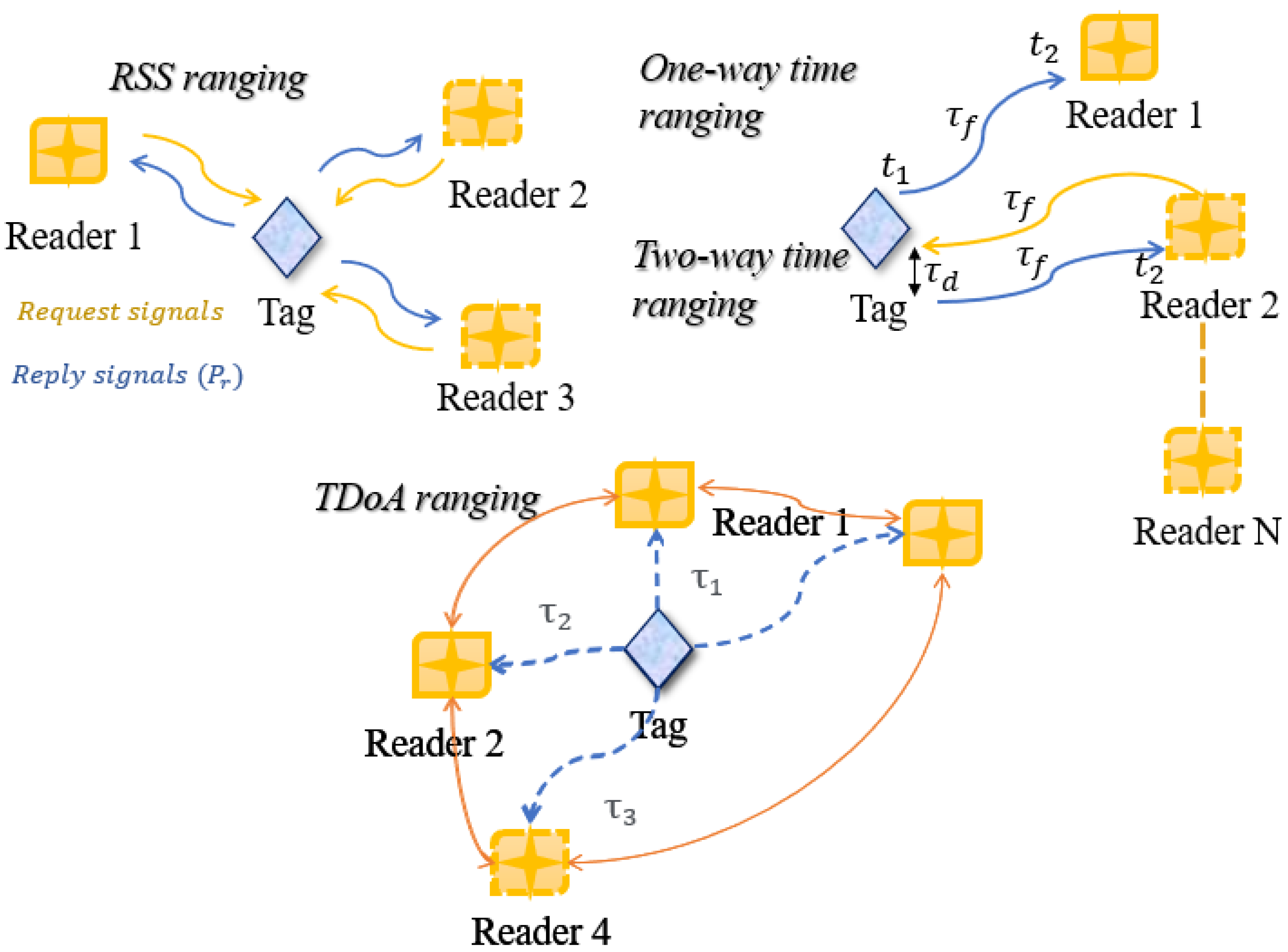
First, to perform ranging, there are many techniques which rely on the characteristics of the signals exchanged between a reader and a tag. The most commonly used techniques are the received signal strength-based ranging (RSS-based) or time-based ranging techniques (Figure 1).
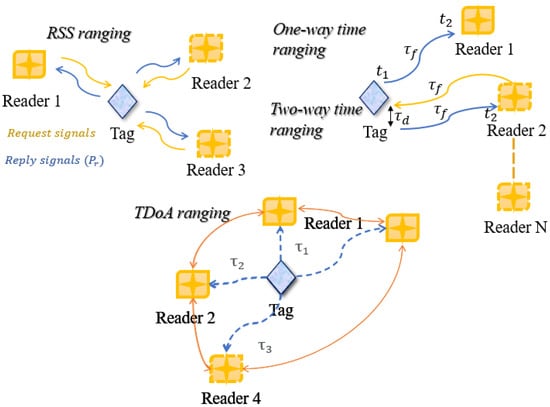
Figure 1.
Indoor localization techniques: RSS-based ranging and time-based ranging (one-way, two-way, and TDoA).
2.1.1. Received Signal Strength-Based Ranging (RSS)
This technique analyses the strength of the signal received at the reader side [26,27]. The strength of the signal is inversely proportional to the distance, that is, the stronger the signal, the farther away the object is. The distance estimate is retrieved from the signal power strength measure using an a priori existing propagation model [11], the simplest being a model of the propagation of signals in free space. Another example is the two-path model which considers the direct path and the reflection from the ground path. The more paths the model contains, the more accurate the distance estimate will be. However, for the model to contain the most paths possible, knowledge of the specific environment where localization needs to be performed is necessary. Thus, this ranging technique is more complicated to implement if high accuracy of the distance estimates is needed [26]. Furthermore, the strength of the propagating signal is very sensitive to environmental factors, such as obstacles (partial or complete blockage of the reader and tag’s line-of-sight (LoS)), multipath reflections, and interferences with other existing signals, as low received signal power could indicate that the tag is far away from the reader but could also indicate that the direct propagation path is blocked by an obstacle. While these factors make RSS-based ranging less reliable for applications requiring highly accurate position information, this technique is easier to implement as it typically does not require additional electronics in the chain of the usual radio propagation systems; moreover, it can operate with different technologies (Bluetooth, Wi-Fi, RFID,) as long as a wireless connection is implemented.
2.1.2. Time-Based Ranging
This technique exploits time measurements to infer the distance information between a reader and a tag [11]. This time is referred to as the “time-of-flight” (ToF) or “time-of-arrival” (ToA) , where d is the unknown distance and c is the speed of light ( m/s). Time-based ranging exists in many forms [28,29], including one-way ranging, two-way ranging, the time-difference-of-arrival (TDoA), and the angle-of-arrival (AoA), each of which is described below.
- One-way ranging: This method requires the internal clocks of the reader and the tag to be perfectly synchronized. The tag sends a packet to the reader containing the information on time instant , which is the instant at which the tag sent this message. The reader receives this information at instant , and is, thus, able to compute the ToF . This method may seem quicker; however, clock differences exist even in identical electronics modules, which can induce errors in the time measurements and, thus, degrade the estimation accuracy.
- Two-way ranging: In this method, the constraint of clock synchronization between the reader and tag is avoided as the time measurement will be mainly performed by the reader. Here, the time measured is the round-trip time (RTT). For this, the reader transmits a request (or interrogation) packet to the tag, to which the latter replies by an acknowledgment packet after a response delay time . The RTT is then computed as , with RTT known, as it is the time duration it took from the time instant the first signal was sent to the time the reply signal arrived to the reader; is known as it is most often specified by the manufacturer.
- Time-difference-of-arrival ranging (TDoA): This method requires multiple readers, which are usually synchronized through a wired network connection. A tag broadcasts a signal, which is received by the readers at different time instants depending on their position. The readers share with each other these times of arrival and compute the differences between them (TDoA). To compute the position of the tag with space coordinates, at least three readers and two TDoA measurements are required. Each TDoA measurement is interpreted geometrically as a hyperbola formed by a set of points to determine the tag position coordinates.
- Angle-of-arrival localization (AoA): This method involves angle measurements and allows not only ranging (distance estimation with ToA), but also localization (coordinates estimation) of a target. In contrast to the triangulation method which requires at least three readers, it is possible to combine a ToA measurement method with AoA measurements to estimate the coordinates. The arrival angle can be determined from the TDoA between signals received by two or more antenna elements of a single reader. For a two-radiating-element antenna array spaced by s, the TDoA depends on the AoA, as described by the equation below [30]:where is the AoA, is the TDoA, and c is the speed of light.
2.2. Error Sources in Distance Estimation with Time-Based Technique
The accuracy of the distance or position information is the most important characteristic and metric of locating systems, more so in indoor localization. This accuracy depends on the quality of the time measurements realized. Many factors can degrade this quality and lead to unreliable measurements and, thus, to their unreliable interpretation when computing the distance estimates. Furthermore, the principal measurement in time-based ranging is the measure of the arrival time of the direct path (first path) signal between the reader and the tag. While the direct path in most cases exists, there can be cases where though it does exist, it is in a non-line-of-sight scenario, for example, if the view between the reader and tag is obstructed (or blocked) by any obstacle (object, walls, etc.). There is also the case where the direct path signal may not arrive at all, and the first arriving signal will be a reflection from one of the objects present in the environment. Indeed, the measurement is considered ideal and most accurate if the first arriving path is a line-of-sight signal, that is, the signal travels in a straight line through a medium with constant known relative permittivity, such as in air.
The possible error sources in time measurements can be divided into three categories as follows: the error sources present in LOS-scenarios, the error sources present in NLOS scenarios, and the error sources present in both LOS and NLOS scenarios, as described below.
2.2.1. Line-of-Sight Scenario (LOS) Specific Error Sources
In this case, no blockage is present in the direct path between the reader and tag. The first and fastest arriving signal will be the direct path signal and the reflections from walls and objects arrive later (as they travel longer paths). This is the case where the measurement will be the most accurate.
2.2.2. Non-Line-of-Sight Scenario (NLOS) Specific Error Sources
In the case where there is blockage between the reader and tag, the first arriving path may be either the direct path signal after traveling through different mediums (non-constant relative permittivity) or a reflection signal from an object. The faster signal is the one that will arrive first and this depends on the permittivities encountered by the signal while traveling, and how far the reflecting object is. In both cases, the error will be “excess delay”, which is an added positive bias in the time measured (and, thus, in the distance estimate). In the case, of the signal being a reflection signal, the distance traveled is naturally longer and, thus, produces a higher time of arrival value. In the case of a direct path signal being obstructed in its way by an obstacle, it is the speed that is reduced. Indeed, the speed of electromagnetic waves traveling in a homogenous material is reduced by compared to the speed of light c. The delay introduced by a material of thickness and permittivity is given by [11]:
Recent measurement campaigns in indoor environments have demonstrated that the mean of the ranging error (distance bias) caused by a material blockage is of the order of the thickness of the obstacle.
2.2.3. Error Sources in Both LOS and NLOS
In all scenarios, LOS or NLOS, if ranging is performed in cluttered complex environments, signal reflections will be present, that is there will be a “multipath effect”. If ranging is performed with narrowband technologies (e.g., Bluetooth, Wi-Fi, RFID), multipath components (signals arriving via different propagation paths) combine at the reader side. These signals can usually not be resolved. Their combination results in constructive or destructive interference, which makes the detection of the direct path signal difficult. Furthermore, in cases of complete blockage, multipath signals are the only signals detected. The problem itself is not that of one reflection (as this only introduces a positive bias as explained previously) but is that the combination of the signals changes its original form which makes its recognition at the reader side impossible [31]. For this reason, UWB technology is preferred in indoor locations because of its fine time resolution compared to narrowband technologies, enabling resolving of signals from each other to recognize the correct ranging signal. The advantages of UWB for ranging are described in detail in the next section. Other sources of errors include co-channel interference, which is caused by coexisting wireless systems sharing the same radio band.
3. UWB Localization from an Industry Point of View
In the earliest stages of development of real-time locating systems (RTLSs), the technologies started from exploitation of ultra-sound, sonar (in radar domains), laser from optics (such as telemeters), and vision technologies (such as in the robotics domain) [27,28]. However, recently, the trend in approaching tracking and localization problems has been to use standard, low cost, and already deployed technologies. Consequently, in the following, we focus only on technologies that are based on radio signal exchange.
Moreover, indoor environments are very challenging; thus, multiple technologies have been proposed to cope with the constraints they impose. Over the years, indoor localization has been studied and performed using several technologies, each conforming to different standards and radio frequencies. These technologies are heterogenous and notably include Wi-Fi, Bluetooth, Radio-frequency IDentification (RFID), and near-field communications (NFC). Although, these wireless communication standards have been designed for other purposes and were not intended for localization and ranging purposes, this did not prevent their exploitation for positioning at the cost of some localization performance limitations, such as shorter range, low or average accuracy, and low detectability coverage. However, since the emergence of UWB technology for specific use in ranging, UWB-based radio chips were subsequently produced ready for deployment in localization and positioning, that is for measurement of the reader-to-object distance and the direction angle of one or several objects. In this section, a review of the existing UWB radio chips and their RTLSs infrastructures (evaluation boards) is presented, and then a comparison of the antennas employed in such systems is provided.
3.1. Overview of Industry Available UWB Chips and Their Evaluation Boards
Table 1 presents a summary of the UWB radio chips available in the industrial market and that are aimed at customers who wish to localize objects inside any indoor environment. The UWB spectrum frequencies these chips operate on and the localization techniques they allow are summarized.

Table 1.
Summary of the UWB radio chips available in the industry, their frequencies, and localization techniques.
In the following, the majority of the listed UWB chips and their characteristics are discussed in detail, notably their antenna types and aimed performances.
3.1.1. Qorvo DWM1000 Chip
The DWM1000 module from American company Qorvo (Greensboro, NC, USA) is based on the DW1000 ultra-wideband (UWB) transceiver IC, which is an IEEE 802.15.4a UWB implementation. It integrates an antenna, all RF circuitry, power management, and clock circuitry in one module. It can be used in two-way ranging or TDOA location systems to locate assets to a precision of 10 cm and supports data rates of up to 6.8 Mbps. The module costs around USD 20 and is available for purchase on the company’s website.
The antenna used in the module is the dielectric chip antenna (ACS5200HFAUWB [39]) manufactured by South Korean company Partron (Hwaseong, South Korea), which is a chip antenna covering UWB bands from 3.2 GHz to 7.2 GHz. The DWM1000, DWM3000 modules, and antenna are shown in Figure 2. The antenna characteristics are summarized in Table 2.
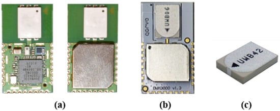
Figure 2.
Company Qorvo’s UWB chips: (a) DWM1000 UWB chip [32], (b) DWM3000 UWB chip [33], (c) frontend monopole ceramic pcb UWB antenna [39].
Table 2.
Characteristics of the UWB monopole antenna integrated in the Qorvo DWM1000 transceiver [39].
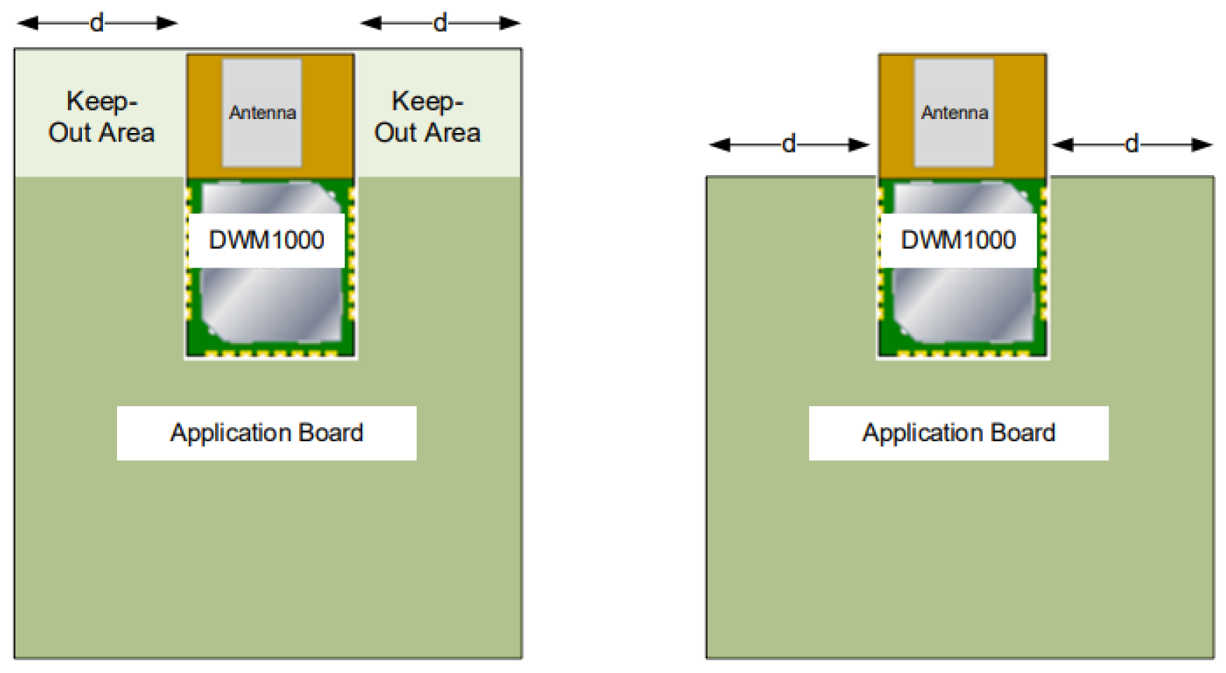
When designing the PCB onto which DWM1000 will be soldered, the proximity of the DWM100 on-board ceramic monopole antenna to metal and other non-RF transparent materials needs to be considered carefully. Two suggested placement schemes are shown in Figure 3. For the best RF performance, Qorvo advices that the ground copper should be flooded in all areas of the application board, except in the areas marked “Keep-Out Area” in the figure, where there should be no metal either side, above or below, such as batteries.

Figure 3.
DWM1000 application board “Keep-out Area” for UWB antenna integration [32].
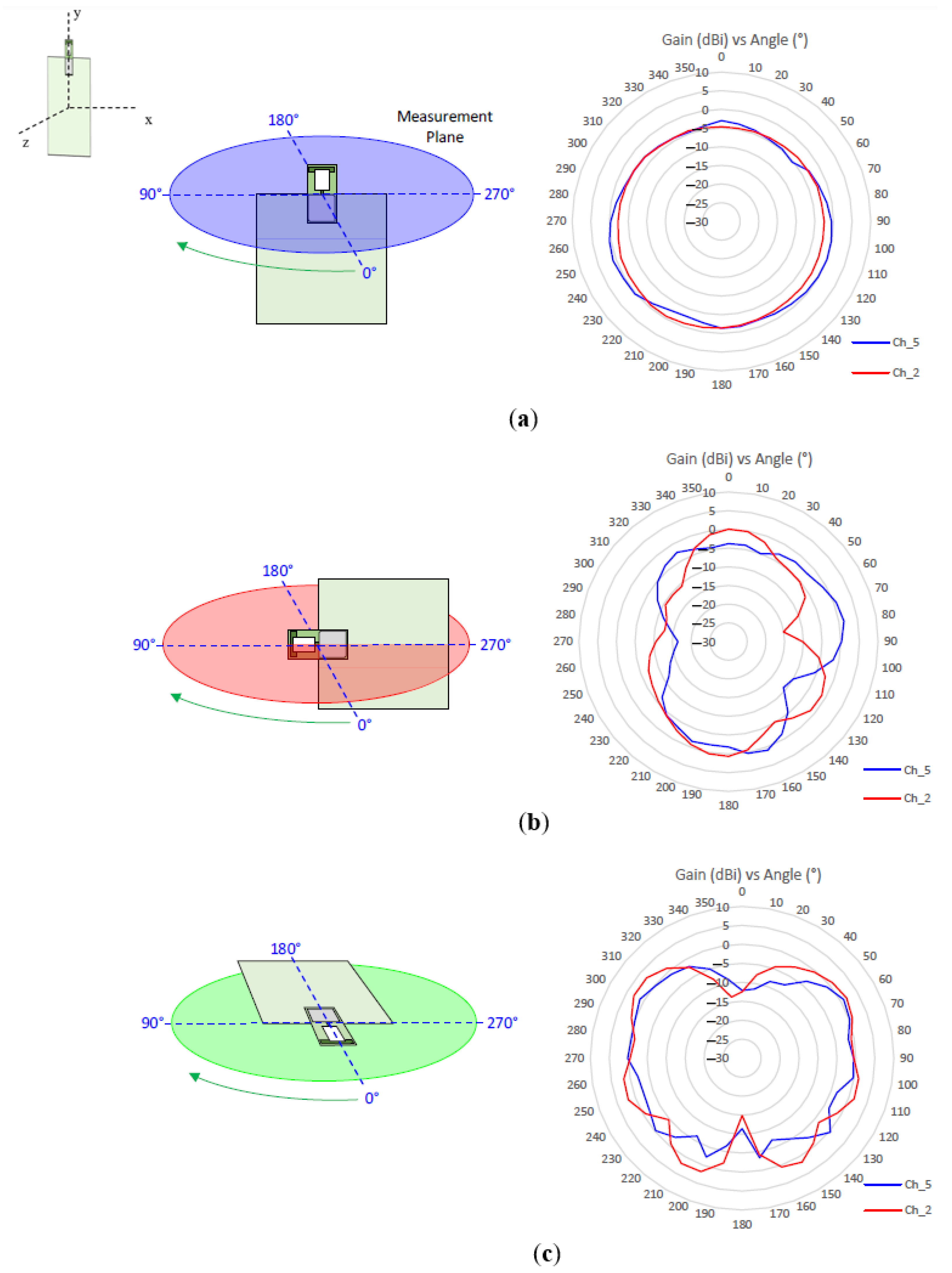
The antenna radiation pattern was measured in an anechoic chamber for three planes and the results were reported by Qorvo [32] (Figure 4). The vertically polarised field (Theta) is associated with the azimuth plane (XZ) and the horizontally polarised field (Phi) is associated with the elevation planes (YZ) and (XY).
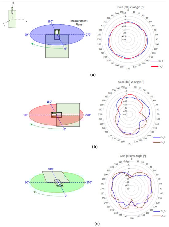
Figure 4.
Module DWM1000’s antenna radiation pattern characteristics [32]: (a) on azimuth plane (plane XZ), (b) on elevation plane 1 (plane YZ), (c) on elevation plane 2 (plane XY).
Figure 4, shows that the monopole antenna has a dipole-like omnidirectional radiation pattern in the XZ plane (Figure 4a), which is beneficial for large coverage for tag detectability in localization. However, it shows that if placed horizontally (plane YZ or plane XY in Figure 4b,c), the radiation pattern is not completely circular and contains nulls in some directions. This means that the module is intended to be positioned vertically upright when used in an RTLS system to avoid power limitations and location inaccuracies.
- DWM1000 evaluation boards:
DWM1000 can be directly connected to an Arduino board to perform ranging. However, the latest version of the module, called DWM3000 [33], is intended to be used with Qorvo’s DWM3000EVB evaluation board [40] (Figure 5a), which is an Arduino form factor compatible shield designed for the evaluation of the DWM3000 module for use in a scalable real-time location system. It costs around USD 30. Another evaluation board for both the DWM1000 and DWM3000 is the ESP32 UWB board [41] from Chinese manufacturer MakerFabs (Shenzhen, China). In the latter, the module is integrated on the same pcb as the microcontroller. It has two versions: the board UWB-ESP32 (Figure 5b), which costs around USD 35, and the board UWB-ESP32-Pro (Figure 5c), which additionally includes an OLED display for the location information, and costs around USD 51.
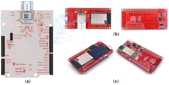
Figure 5.
Evaluation boards for Qorvo’s DWM1000 and DWM3000 modules: (a) Qorvo Arduino shield for DWM3000 [40], (b) ESP32 all-in-one evaluation board for UWB tracking [41], (c) ESP32-Pro (with display) all-in-one evaluation board for UWB tracking [41].
3.1.2. STMicroelectronics’ MOD1 Chip
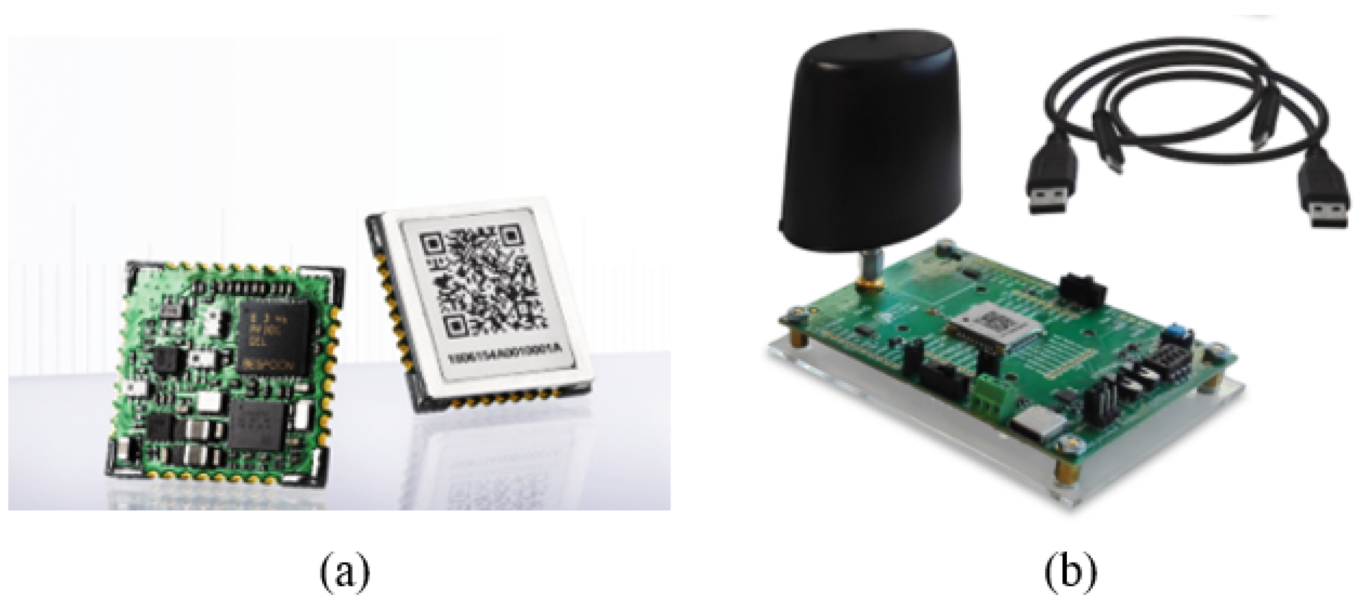
Similarly to the DWM1000 and DWM3000 modules, the UWB MOD1 module is a surface mount module for UWB high precision (Figure 6a) developed by a French company previously called BeSpoon, which is now part of STMicroelectronics. It was designed for use in warehousing and logistics in companies, personal navigation devices, security and building controls, robotics, wearable sensors, healthcare maintenance, virtual reality (VR), and gaming. It supports two-way ranging and achieves precisions of down to 10 cm; it has data rates of up to 2 Mb/s.
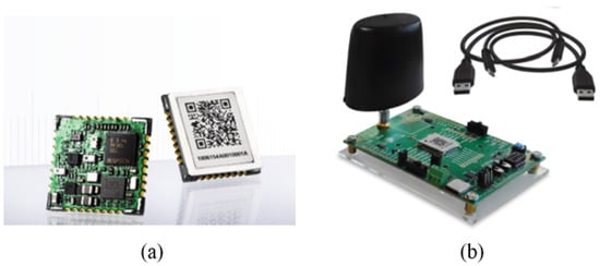
Figure 6.
STMicroelectronics: (a) UWB module MOD1 [38], (b) B-UWB-MEK1 application board for MOD1 module with external antenna [42].
The module has an embedded API for firmware operation and updates and master–slave mode selection. The MOD1 module itself does not include an antenna and is only available when integrated in its evaluation kit (Figure 6b), which is described below.
- MOD1 evaluation board:
The MOD1 chip is only available for purchase when integrated in the evaluation board B-UWB-MEK1 by STMicroelectronics (Figure 6b) [42], which is equipped with an STM32 microcontroller. It can be used as a fixed or mobile device. The use of from four to up to sixty boards is possible to prototype a location system. It is only available for purchase on demand.
The MEK1 evaluation kit contains two identical UWB antennas of type 3D monopole. Its characteristics are summarized in Table 3.
Table 3.
Characteristics of the UWB 3D monopole antenna of the STMicroelectronics B-UWB-MEK1 evaluation board [42].
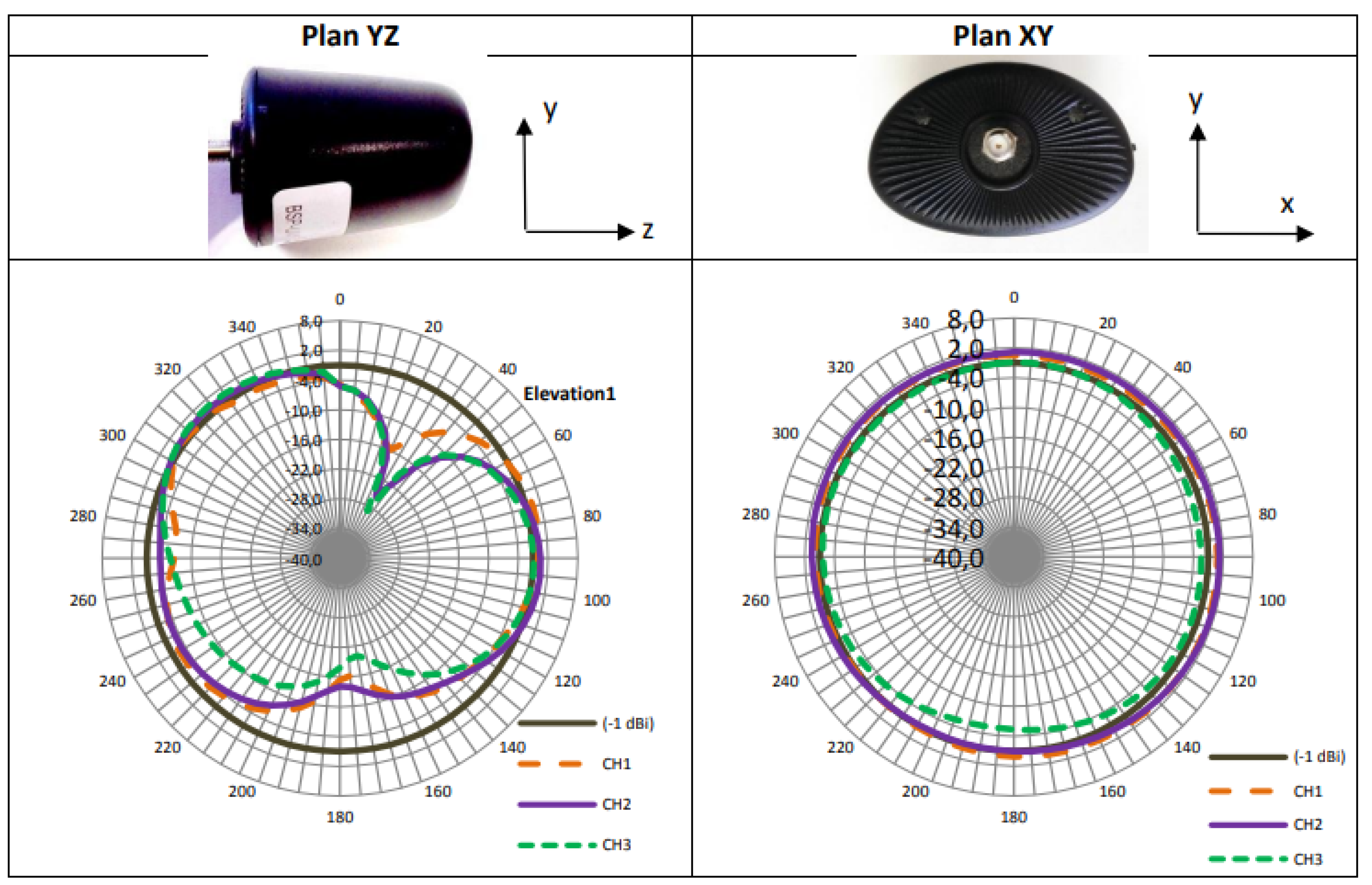
Additionally, the radiation patterns of the monopole antenna are shown in Figure 7 for both the azimuth and elevation planes, and for all the center frequencies for the UWB channels: 1 (orange line), 2 (purple line), and 3 (green line), all illustrated with reference to—1 dBi of gain (black line).
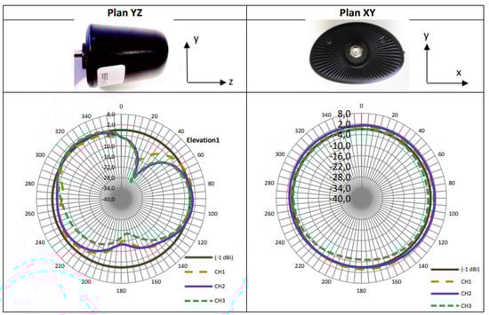
Figure 7.
MEK1 UWB antenna radiation pattern characteristics on the azimuth and elevation planes [43].
Since the commercial antenna is linearly polarized (vertical polarization), it has E-plane (elevation) and H-plane radiations (azimuth). The commercial antenna for channel 2 has omnidirectional radiation along with a gain of 2 dBi.
3.1.3. UWB Chips Interoperable with Apple’s U1 Chip for Interactions
Apple announced the availability of UWB modules and development kits for interaction with its U1 chip. The modules are from either companies: American company Qorvo or Dutch company NXP Semiconductors (Eindhoven, TheNetherlands). First, Qorvo’s module DWM3000 which was previously described is compatible for interaction with the U1 chip. Second, development kits that contain the Trimension chip from the company NXP (the SR040 or SR150 chips) can be used by third party device developers. Since the DWM3000 architecture is similar to the DWM1000 described before, we focus here on the NXP-based kits. These kits are commercialized by NXP’s partners including Sunway Communications, Murata, and Mobile Knowledge. They are approved by Apple® for the purpose of evaluating UWB-enabled accessories that leverage Apple’s nearby interaction framework in order to interact with Apple products that include the U1 chip. These modules and evaluation boards are listed below.
- Sunway Communications’s SW-EVK-2 board based on NXP SR150 chip:
Chinese company Sunway Communications developed a FiRa [44] and an IEEE 802.15.4z UWB compliant wireless transceiver module [37] (Figure 8a) based on NXP’s SR150 chip [35]. It enables the location of objects in RTLSs to a secure range precision of 10 cm and an angle precision of 3 degrees. It involves the integration of the SR150 SoC, antenna interface support, power management, and clock control, which simplifies design integration with minimal RF design required (external antenna). The module costs around USD 24.
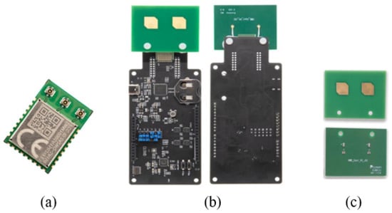
Figure 8.
Sunway Communications equipment: (a) UWB module based on NXP’s SR150 chip for ranging and direction finding [37], (b) application board SW-EVK-2 with UWB antennas [45], (c) UWB pcb dual patch antenna [46] for the SW-EVK-2 application board.
It supports TWR, TDoA, or phase-difference of arrival (PDoA) for the AoA scheme in a variety of applications, such as industrial, healthcare, smart home, smart retail RTLS, secure hands-free payment, and automotive access.
The module supports UWB channels 5, 6, 8, and 9 (frequency range from 6.24 to 8.24 GHz) and enables support for a 3 × 1 element antenna array with JSC type antenna connectors. The evaluation board for this module and its antenna array are illustrated in Figure 8b,c respectively.
The Sunway UWB Evaluation Kit (Sunway UWB EVK-2) [45] is composed of two Sunway UWB boards in an anchor–tag configuration to allow locating the module operating as a tag and to build and evaluate an RTLS. This board is mounted on an NXP QN9090 board for operation. The Sunway kit contains two boards and costs around USD 1115.
The characteristics of the antenna array [46] used in the evaluation kit are summarized in Table 4.
Table 4.
Characteristics of the UWB dual patch antenna [46] of the Sunway evaluation board [45].
From the information above, it is important to note that the Sunway module (Figure 8a) [37] accommodates all UWB channels 5, 6, 8, and 9. However, the Sunway dual antenna (Figure 8c) is only designed to accommodate UWB channel 5; thus, if this antenna is used in the evaluation kit, ranging may only be performed on channel 5.
At the time of writing of this article, the radiation pattern characteristic plot of the antenna had not been published by Sunway.
3.1.4. Murata’s Type2BP-EVK Board Based on NXP SR150 Chip
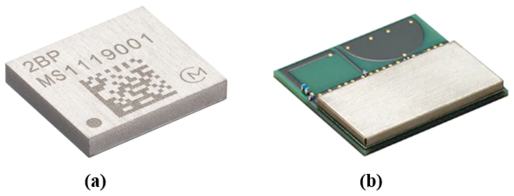
The development kit Type2BP by Japanese company Murata, Kyoto, Japan (Figure 9a–c represent the top, bottom and perspective views of the board) [47] based on NXP’s chip SR150 enables a wide range of IoT devices to perform localization tasks or to create a setup with multiple UWB anchors. The kit is based on Murata’s Type2BP [48] ultra-small UWB module, which includes clock, filters, and peripheral components, as well as NXP’s QN9090 Bluetooth LE solution and a USB-UART conversion IC. The kit costs around 135$. The Type-2BP can be controlled through QN9090 with power being supplied via a UWB cable or from the COM port of a PC. The kit integrates an on-board 3-element patch UWB antenna array.
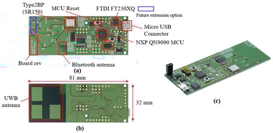
Figure 9.
Murata UWB Trimension™ SR150-based application board Type2BP EVK [47] with UWB antenna: (a) top view, (b) bottom view, (c) perspective view.
In addition to the TYPE2BP module (Figure 10a) which is employed in the Murata kit and based on the NXP SR150 chip, the company also developed another module called TYPE2DK (Figure 10b), which is instead based on the NXP SR040 module. There are also UWB modules which are based on the NXP UWB chipset. Both modules integrate the NXP UWB chipset, filters, clock, and peripheral components. These modules are ideally suited for general IoT devices, where TYPE2BP [48] is suited for the reader role and the TYPE2DK [49] is more suited for the tag role.

Figure 10.
Murata UWB NXP-based modules: (a) Type2BP (built upon the SR150 module), (b) Type2DK (built upon the SR40 module).
For further details, the Murata TYPE2BP module is compliant with IEEE802.15.4z HRP PHY. It supports TWR, TDoA, and the 2D and 3D AoA schemes. It supports UWB channels 5 and 9, and data rates of 6.81 Mbps, 7.8 Mbps, 27.24 Mbps, and 31.2 Mbps. Its characteristics are summarized in Table 5.
Table 5.
Characteristics of Murata Type2BP module (based on NXP SR150).
In contrast to the TYPE2BP module, the Type2DK module [49] based on NXP’s SR40 is an all-in-one UWB + Bluetooth LE combo module, which integrates NXP QN9090 Bluetooth® LE + MCU chipset and on-board antennas for UWB and Bluetooth. This module can be used as a standalone tag, which operates by coin-cell battery. It can also be used with the Murata Type2BP evaluation kit described previously to perform ranging tests. Other characteristics of the module are summarized in Table 6.
Table 6.
Characteristics of Murata Type2DK module (based on NXP SR040).
To conclude regarding the Murata modules, the Type2BP module does not contain any antenna. It contains the support (only) of 3 UWB antennas, which in the evaluation kit are the elements of a 3-patch-type element antenna array UWB. The Murata Type2DK has on-board integrated antennas, one for Bluetooth LE and the other one for UWB, of the printed monopole type. Other specifications of the antennas are provided by the manufacturer upon purchase.
3.2. Summary of the Antennas Present in Industrial UWB Chips and Evaluation Board
To conclude the technical review of UWB real-time located systems, with a focus on antennas, Table 7 and Table 8 present a summary of the UWB modules, their evaluation boards, and antennas. Table 7 highlights if the UWB chip itself or its available evaluation boards integrate an antenna or not. Table 8 summarizes the characteristics of the UWB antennas integrated with each UWB chip or evaluation board.
Table 7.
Summary of the industrial UWB chips, their evaluation boards, and their antenna integration.
Table 8.
Summary of the UWB antenna characteristics of the industrial UWB chips and/or their evaluation boards.
4. Discussion of the Antenna Influence on Localization Performance
The attempt to range and localize objects with electronic devices comprising transmit and receive antennas, especially in time-based schemes which mostly employ UWB technology, is a sensitive process as the final result depends greatly on the nature of the captured signal at the antenna stage. Thus, frontend design must be meticulous to detect the most correct signal, that is, the shortest path signal, which leads to computation of the distance estimate that is closest to the real distance. The shortest path signal can be the direct path or the first arriving reflection in the case of complete blockage between the reader and tag. Consequently, the type of antennas used at both the reader and tag matter significantly in the sense that they can either improve or degrade the distance estimation depending on their characteristics, such as the type of antenna, gain, polarization, radiation pattern, etc. In the following, we discuss the influence antenna characteristics can have on the quality of ranging results.
4.1. Influence on the Localization Range
The range of a wireless communication system is directly related to the received power at the receiver side, in this case, at the reader side. This applies in all schemes, not just in received-signal strength (RSS)-based localization systems, but also in time-based systems, such as UWB transceivers. Indeed, as the received power decreases with increased distance between the reader and tag, it determines the limit distance at which the transceiver can no longer detect the signal from the tag and, thus, can no longer perform ranging.
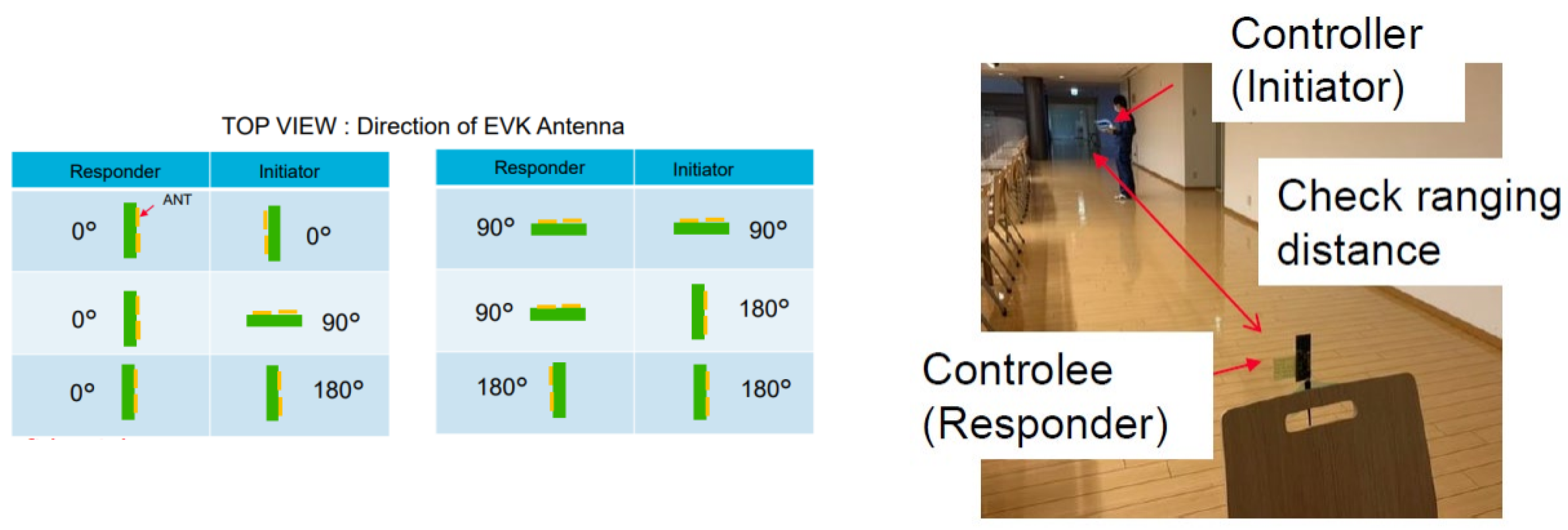
Industrial manufacturers of UWB transceivers sometimes publish the measured performance of their UWB chips and evaluation boards, such as Murata for example. The performance in terms of the reading range of their NXP SR150 chip-based TYPE2BP evaluation kit was measured and reported. Figure 11 presents Murata’s measurement setup and environment, using two TYPE2BP boards integrating transmit and receive antennas. The reported results on achieved range are presented in Table 9.
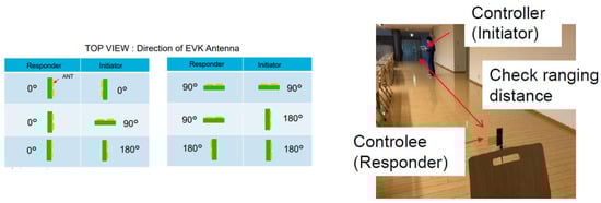
Figure 11.
Range measurement setup from Murata Type2BP evaluation board [47].
Table 9.
Range measurement results from Murata Type2BP evaluation board [47].
This measurement is aimed to infer the maximum possible reading range at which the tag can be detected. Two Type2BP EVK are connected in a controller (reader) and controlee (tag) configuration to check whether long ranging is possible. While doing this, the results are reported with several conditions as stated by the manufacturer. These conditions correspond to the different possible antenna orientations of the reader and tag relative to each other. The reported ranges are summarized in the table below.
The evaluation kit uses patch-type antennas with a theoretical directional radiation, and with linear polarization. Consequently, the best case scenario is the condition orientation for the responder and orientation for the initiator, which is reported to achieve a maximum reading range of 50 m. Linear polarization affects the other cases in the received power as cross-polarization (–, –) induces power loss [50,51]. Moreover, even in cases where there is no cross-polarization, the radiation pattern also affects the detectability, especially at longer distances, in cases where the antennas are not facing each other (such as in –, – and –).
For this reason, a solution would be to design omnidirectional reader and tag antennas to ensure that the transceivers do not miss each other in the search phase and discovery process during two-way ranging, no matter how they are placed relative to each other. However, the antenna used will depend on where and how the product is going to be used. For example, in a wearable tag where the orientation is not known, an omnidirectional antenna is probably the most reliable [52], whereas in a fixed anchor, it may be more efficient to use a radiation pattern if the anchor is fixed to a wall or surface to help shield the antenna from the surface and to prevent performance loss.
These observations show the significant effect of the transmit and receive antennas on the performance of the RTLS in terms of the range, especially in LOS scenarios. If we consider an NLOS scenario, with an obstacle between the reader and tag, the direct path will arrive later than expected because of the obstacle medium’s relative permittivity. This will add a positive bias to the ranging estimate. The worst case scenario is if the direct path is lost entirely because of significant power loss. Similarly, the signal could be cancelled if the direct path is mixed with an out-of-phase short multipath. In either case, the transceiver fails to find the true direct first path and will lock onto the next detectable shortest multipath signal [53], and the resulting distance estimate will be longer than the true distance. To tackle these problems, Qorvo [53] suggests system-based adjustments, such as algorithms to recognize whether the timestamp returned by the transceiver is in fact a timestamp of a multipath signal or not. A similar approach was proposed in [54]. Moreover, an antenna-based solution would be the design of higher gain antennas that would allow for a large link margin and prevent power loss [55]. Additionally, a reduction in multipath signals could be achieved by desiging both the reader and the tag antennas to have circular polarization of the same sense [50]. This would enable filtering to some extent of multipath signals coming from a reflection on metal objects, which would decrease the chance of combination of a multipath signal with the direct path at the receiver side.
4.2. Influence on the Tag Orientation Dependence
From the previous Table 9, the worst case scenario is when the responder and the initiator antennas are in a 180°–180° orientation configuration relatively to each other. It can be seen that the maximum distance at which the responder is detected is 4.5 m, which means that further from this distance not only is ranging impossible but its presence cannot be detected. Taking into account the application of UWB transceivers, these are mainly intended for use in indoor environments with several mobile objects. Unlike, for example, RFID tracing or Bluetooth tracing, a range of 4.5 m is too low for UWB deployment areas (hospitals, airports, construction mines, etc.). Furthermore, in such areas, tags and objects are mobile and their orientation cannot be manually adjusted to face the reader’s antenna nor to match its vertical or horizontal polarization. For this reason, solutions such as circular polarization of the reader antennas [50,55] are advised to mitigate cross-polarization-induced power loss, even while the tag’s polarization may be kept linear for design simplicity.
4.3. Influence on the Accuracy
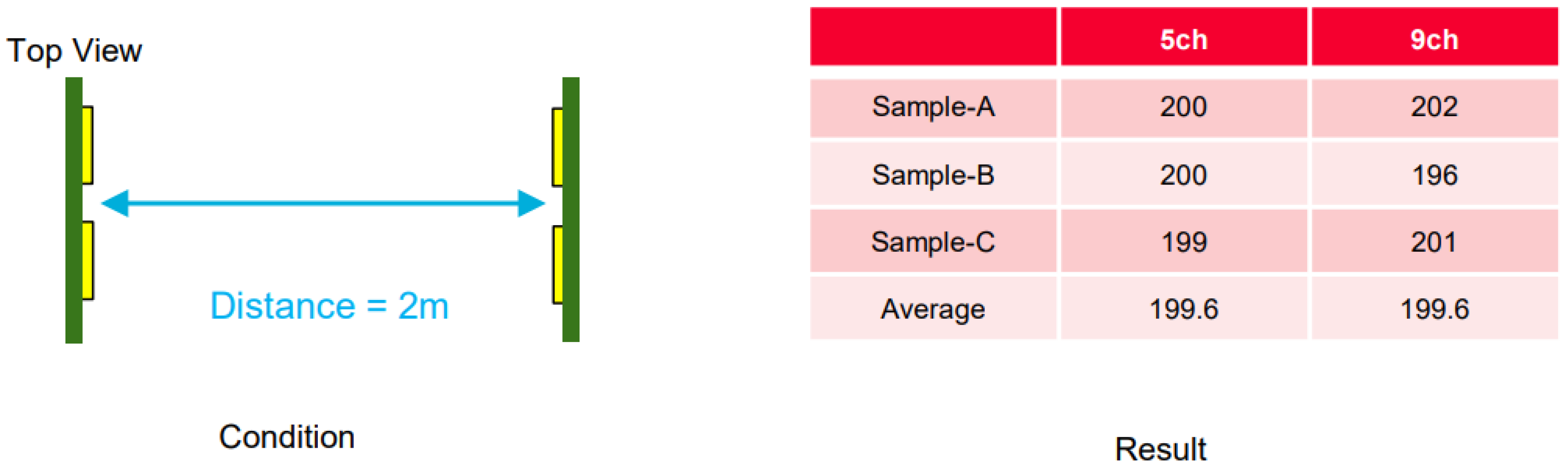
After assessing the reading range, the performance in terms of the accuracy of the ranging estimates of the NXP SR150 chip-based TYPE2BP evaluation kit was similarly measured and reported. Figure 12 presents Murata’s measurement setup and environment using two TYPE2BP boards.
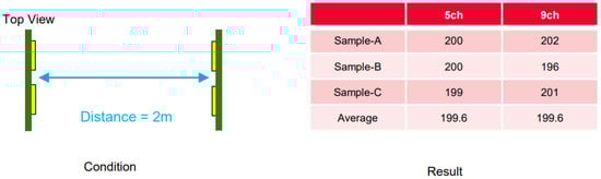
Figure 12.
Accuracy measurement from Murata Type2BP evaluation board [47].
For this measurement, the condition of the antennas is that they are placed facing each other. In most cases, the conclusions drawn on accuracy are statistical or based on many measured samples by ranging and comparing to the real distance. The table shows that three samples, A, B, and C, of ranging were taken at both channel 5 (centered at 6.49 GHz) and channel 9 (centered at 7.9 GHz) and were finally averaged to one value at the end (the values are reported in cm).
Taking into account the real distance of 2 m and the reported average detected distance at both channels of 1.99 m, an accuracy of 99 % was obtained, which is most likely to have been due to the fine temporal resolution of the UWB signal itself and the placement of the antennas in complete line-of-sight without any blockage nor reflecting objects and at a distance of only 2 m. These observations show that, in fact, the theoretical UWB accuracy level (that is around 30 cm) can be achieved; however, only in adjusted conditions, as seen in the previous cases.
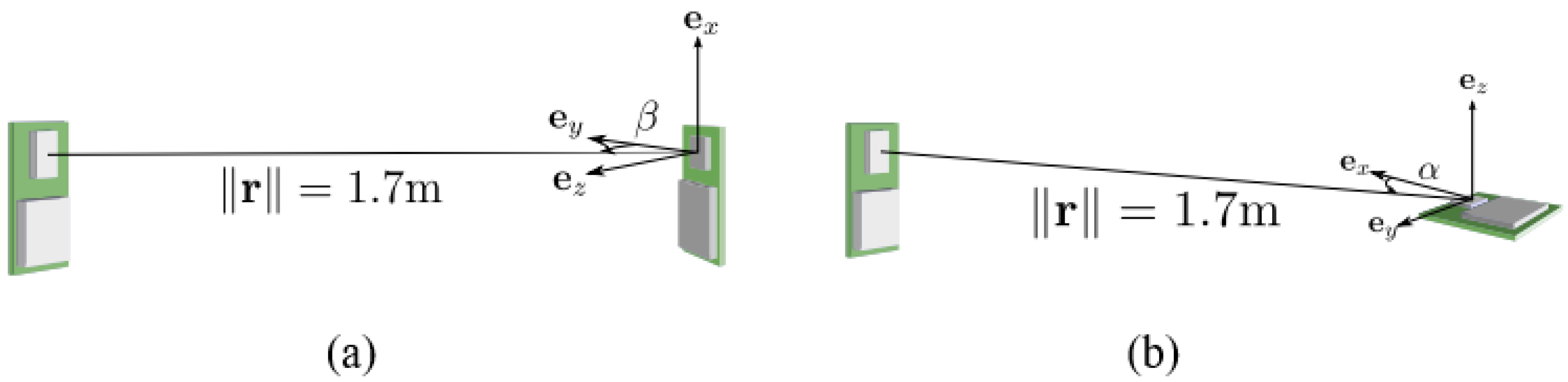
Indeed, the accuracy can be affected by factors such as the antenna orientations and multipath reflections. First, the antenna orientation effect occurs as the group delay varies not only with the frequency [56] but also with the direction angles (azimuth and elevation) [57]. For example, in [58], two DWM1000 (Qorvo) transceivers, including their Partron Dielectric Chip antennas, were placed 1.7 m apart. One antenna was then rotated around its x-axis (Figure 13a), then around its z-axis (Figure 13b), while range measurements were taken. The distance estimate error was calculated and plotted with respect to the angles. It was found that errors between 10 cm and 40 cm occurred depending on the angles and formed after rotating the antenna.
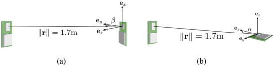
Figure 13.
Assessment of the effect of antenna orientation on the ranging accuracy with Qorvo DWM1000 transceivers [58]: (a) rotation of the antenna on its x-axis, (b) rotation of the antenna on its z-axis.
Thus, an antenna rotated on one of its axes will delay the signal differently depending on the direction and, thus, depending on the radiation pattern gain. Furthermore, because this delay is used to calculate the time-of-flight (ToF) in two-way ranging, a slight difference between the input delay given to the module and the actual delay will engender different ToF and distance estimates, and, thus, affect the accuracy. For example, Qorvo recommends in an application note [52] for their DWM1000 module to maintain an antenna delay inferior to 100 ps compared to the delay of the useful orientation of the antenna to reduce inaccuracies. For a UWB channel of bandwidth 500 MHz (pulse width 2 ns), a 100 ps delay would translate into a maximum error of 6 cm in the distance estimate for propagation in free space at the speed of light. Nevertheless, a conclusion on the effect of the antenna orientation would be that omnidirectional antennas with stable gain in all directions of the radiation pattern would yield less variations in the antenna delay even if the antenna is rotated and, thus, are recommended to avoid orientation-induced errors.
Second, concerning the multipath effect, the accuracy depends heavily on the environment, and for practical applications, these environments cannot be reliably predicted. This calls for the design of antennas which are robust to reflections and multipaths. For this reason, a solution was proposed in our previous work [50], which consists in mitigating multipath signals with circular polarization filtering. This method requires both the reader and tag antenna to have circular polarization of the same sense (either right-hand or left-hand), which would enable filtering out of reflections on metal as these will switch the CP sense in the middle of the path before arrival.
5. Conclusions
This article presented a study of UWB locating systems by first highlighting the error sources in indoor environments that can affect time-based localization. Then, a technical review of the currently available industrial UWB chips and real-time locating systems used for object monitoring in indoor scenarios and complex environments was presented. Furthermore, the antennas employed in the listed systems and their characteristics were highlighted and summarized. A discussion on the influence of frontend antennas of UWB transceivers on the localization quality in terms of reading range, accuracy, and object-orientation-independent detectability was provided and solutions were suggested.
Author Contributions
The individual contributions of the authors to the realization of this work are as follows: Conceptualization, A.B.; methodology, R.S., F.F. and A.B.; software: A.B; validation, R.S., F.F. and L.L.; formal analysis, A.B.; investigation, A.B.; resources, A.B.; data curation, A.B.; writing—original draft preparation, A.B.; writing—review and editing, F.F., R.S. and L.L.; supervision, R.S., F.F. and L.L.; project administration, R.S.; funding acquisition, R.S. All authors have read and agreed to the published version of the manuscript.
Funding
This research was funded by the Nano 2022 project, grant number 198938.
Data Availability Statement
The original contributions presented in the study are included in the article. Further enquiries can be directed to the corresponding author.
Acknowledgments
The authors would like to thank the partners participating in the LEANPOD project 2020 for meaningful discussions.
Conflicts of Interest
The authors declare no conflicts of interest.
Abbreviations
The following abbreviations are used in this manuscript:
| RTLS | Real-Time Locating System |
| UWB | Ultra-Wide Bandwidth |
| TWR | Two-Way Ranging |
| TDoA | Time Difference of Arrival |
| AoA | Angle of Arrival |
| LOS | Line Of Sight |
| NLOS | Non Line Of Sight |
References
- Bacci, G.; Falletti, E.; Fernández-Prades, C.; Luise, M.; Margaria, D.; Zanier, F. Chapter 2—Satellite-Based Navigation Systems. In Satellite and Terrestrial Radio Positioning Techniques; Dardari, D., Falletti, E., Luise, M., Eds.; Academic Press: Oxford, UK, 2012; pp. 25–74. [Google Scholar] [CrossRef]
- Duran, M.A.; D’Amico, A.A.; Dardari, D.; Rydström, M.; Sottile, F.; Ström, E.G.; Taponecco, L. Chapter 3—Terrestrial Network-Based Positioning and Navigation. In Satellite and Terrestrial Radio Positioning Techniques; Dardari, D., Falletti, E., Luise, M., Eds.; Academic Press: Oxford, UK, 2012; pp. 75–153. [Google Scholar] [CrossRef]
- Álvarez-Merino, C.S.; Luo-Chen, H.Q.; Khatib, E.J.; Barco, R. WiFi FTM, UWB and Cellular-Based Radio Fusion for Indoor Positioning. Sensors 2021, 21, 7020. [Google Scholar] [CrossRef]
- Wang, L.; Zawodniok, M. RSSI-based localization in cellular networks. In Proceedings of the 37th Annual IEEE Conference on Local Computer Networks—Workshops, Clearwater, FL, USA, 22–25 October 2012; pp. 820–826. [Google Scholar] [CrossRef]
- You, Y.; Wu, C. Indoor Positioning System With Cellular Network Assistance Based on Received Signal Strength Indication of Beacon. IEEE Access 2020, 8, 6691–6703. [Google Scholar] [CrossRef]
- Sanpechuda, T.; Kovavisaruch, L. A review of RFID localization: Applications and techniques. In Proceedings of the 2008 5th International Conference on Electrical Engineering/Electronics, Computer, Telecommunications and Information Technology, Krabi, Thailand, 14–17 May 2008; pp. 769–772. [Google Scholar]
- Finkenzeller, K. RFID Handbook: Fundamentals and Applications in Contactless Smart Cards and Identification, 3rd ed.; Wiley: Hoboken, NJ, USA, 2010. [Google Scholar]
- Yang, L.; Giannakis, G.B. Ultra-wide band communications, an idea whose time has come. IEEE Signal Process. Mag. 2004, 4, 1053–5888. [Google Scholar]
- IEEE 802.15.4-2020; Revision of IEEE Standard 802.15.4-2015. IEEE Standard for Low-Rate Wireless Networks; IEEE Standards Association: Piscataway, NJ, USA, 2020.
- IEEE 802.15.4z-2020; Amendment to IEEE Standard 802.15.4-2020. IEEE Standard for Low-Rate Wireless Networks–Amendment 1: Enhanced Ultra Wideband (UWB) Physical Layers (PHYs) and Associated Ranging Techniques; IEEE Standards Association: Piscataway, NJ, USA, 2020.
- Dardari, D.; Conti, A.; Ferner, U.; Giorgetti, A.; Win, M.Z. Ranging with Ultrawide Bandwidth Signals in Multipath Environments. Proc. IEEE 2009, 97, 404–426. [Google Scholar] [CrossRef]
- Romme, J.; Heuvel, J.H.C.v.; Dolmans, G.; Selimis, G.; Philips, K.; de Groot, H. Measurement and analysis of UWB radio channel for indoor localization in a hospital environment. In Proceedings of the 2014 IEEE International Conference on Ultra-WideBand (ICUWB), Paris, France, 1–3 September 2014; pp. 274–279. [Google Scholar] [CrossRef]
- Jiang, L.; Hoe, L.N.; Loon, L.L. Integrated UWB and GPS location sensing system in hospital environment. In Proceedings of the 2010 5th IEEE Conference on Industrial Electronics and Applications, Taichung, Taiwan, 15–17 June 2010; pp. 286–289. [Google Scholar] [CrossRef]
- Wichmann, J. Indoor positioning systems in hospitals: A scoping review. Digit. Health 2022, 8, 20552076221081696. [Google Scholar] [CrossRef]
- San Martín, J.; Cortés, A.; Zamora-Cadenas, L.; Svensson, B.J. Precise Positioning of Autonomous Vehicles Combining UWB Ranging Estimations with On-Board Sensors. Electronics 2020, 9, 1238. [Google Scholar] [CrossRef]
- Kim, K.; Lee, S.; Yoo, T.; Kim, H. Vehicular Localization Framework with UWB and DAG-Based Distributed Ledger for Ensuring Positioning Accuracy and Security. Electronics 2023, 12, 4756. [Google Scholar] [CrossRef]
- Apple Developer, UWB-Based Car Keys. Available online: https://developer.apple.com/videos/play/wwdc2021/10084/ (accessed on 2 February 2024).
- Ziegler, M.; Kianfar, A.E.; Hartmann, T.; Clausen, E. Development and Evaluation of a UWB-Based Indoor Positioning System for Underground Mine Environments. Min. Metall. Explor. 2023, 40, 1021–1040. [Google Scholar] [CrossRef]
- Li, M.-G.; Zhu, H.; You, S.-Z.; Tang, C.-Q. WB-Based Localization System Aided With Inertial Sensor for Underground Coal Mine Applications. IEEE Sens. J. 2020, 20, 6652–6669. [Google Scholar] [CrossRef]
- Wisiak, K.; Jakić, M.; Hartlieb, P. Application of Ultra-Wide Band Sensors in Mining. Sensors 2022, 23, 300. [Google Scholar] [CrossRef]
- Liu, R.; Deng, Z.; Cao, Z.; Shalihan, M.; Lau, B.P.; Chen, K.; Bhowmik, K.; Yuen, C.; Tan, U.X. Distributed Ranging SLAM for Multiple Robots with Ultra-WideBand and Odometry Measurements. In Proceedings of the 2022 IEEE/RSJ International Conference on Intelligent Robots and Systems (IROS), Kyoto, Japan, 23–27 October 2022; pp. 13684–13691. [Google Scholar] [CrossRef]
- Benouakta, A.; Nguyen, T.M.; Ferrero, F.; Lizzi, L.; Staraj, R. Design of a Multi-Standard UWB-LoRa Antenna Structure and Transceiver Board for High-Accuracy and Long-Range Localization Applications. Electronics 2023, 12, 4487. [Google Scholar] [CrossRef]
- Piavanini, M.; Barbieri, L.; Brambilla, M.; Cerutti, M.; Ercoli, S.; Agili, A.; Nicoli, M. A Self-Calibrating Localization Solution for Sport Applications with UWB Technology. Sensors 2022, 22, 9363. [Google Scholar] [CrossRef]
- Umek, A.; Tomažič, S.; Kos, A. Application for Impact Position Evaluation in Tennis Using UWB Localization. Procedia Comput. Sci. 2019, 147, 307–313. [Google Scholar] [CrossRef]
- Waqar, A.; Ahmad, I.; Habibi, D.; Phung, Q.V. Analysis of GPS and UWB positioning system for athlete tracking. Meas. Sens. 2021, 14, 100036. [Google Scholar] [CrossRef]
- Dardari, D.; Di Dio, M.; Emmanuele, A.; Fontanella, D.; Gezici, S.; Gholami, M.R.; Kieffer, M.; Lagunas, E.; Louveaux, J.; Mallat, A.; et al. Chapter 5—Innovative Signal Processing Techniques for Wireless Positioning. In Satellite and Terrestrial Radio Positioning Techniques; Dardari, D., Falletti, E., Luise, M., Eds.; Academic Press: Oxford, UK, 2012; pp. 207–315. [Google Scholar] [CrossRef]
- Dardari, D.; Closas, P.; Djuric, P.M. Indoor Tracking: Theory, Methods, and Technologies. IEEE Trans. Veh. Technol. 2015, 64, 1263–1278. [Google Scholar] [CrossRef]
- Syazwani, N.C.; Haliza Abdul Wahab, N.; Sunar, N.; Ariffin, S.H.; Yinn Wong, K.; Aun, Y. Indoor Positioning System: A Review. Int. J. Adv. Comput. Sci. Appl. 2022, 13, 477–490. [Google Scholar] [CrossRef]
- del Peral-Rosado, J.A.; Raulefs, R.; Lopez-Salcedo, J.A.; Seco-Granados, G. Survey of Cellular Mobile Radio Localization Methods: From 1G to 5G. IEEE Commun. Surv. Tutor. 2018, 20, 1124–1148. [Google Scholar] [CrossRef]
- Sipal, V.; John, M.; Neirynck, D.; McLaughlin, M.; Ammann, M. Advent of practical UWB localization: (R)Evolution in UWB antenna research. In Proceedings of the 8th European Conference on Antennas and Propagation (EuCAP 2014), The Hague, The Netherlands, 6–11 April 2014; pp. 1561–1565. [Google Scholar] [CrossRef]
- Falsi, C.; Dardari, D.; Mucchi, L.; Win, M.Z. Time of Arrival Estimation for UWB Localizers in Realistic Environments. EURASIP J. Adv. Signal Process. 2006, 2006, 032082. [Google Scholar] [CrossRef]
- Qorvo DWM1000 UWB Transceiver. Available online: Https://www.qorvo.com/products/p/DWM1000 (accessed on 3 December 2023).
- Qorvo DWM3000 UWB Transceiver. Available online: Https://www.qorvo.com/products/p/DWM3000 (accessed on 3 December 2023).
- Apple Nearby Interactions. Locate and Interact with Nearby Devices Using Identifiers, Distance, and Direction. Available online: https://developer.apple.com/documentation/nearbyinteraction/ (accessed on 9 December 2023).
- NXP Trimension SR150 UWB Transceiver. Available online: https://www.nxp.com/products/wireless-connectivity/trimension-uwb/trimension-sr150-secure-uwb-solution-for-iot-devices:SR150 (accessed on 30 April 2023).
- NXP Trimension SR040 UWB Transceiver. Available online: https://www.nxp.com/products/wireless-connectivity/trimension-uwb/trimension-sr040-reliable-uwb-solution-for-iot:SR040 (accessed on 30 April 2023).
- Sunway Communications UWB Transceiver for Ranging and Direction Finding. Available online: https://en.sz-sunway.com/product/wireless/RF-Connectivity-Module/383.html (accessed on 18 December 2023).
- STMicroelectronics B-UWB-MOD1 Ultra-Wideband Module for High-Precision Indoor Location. Available online: Https://www.st.com/en/wireless-connectivity/b-uwb-mod1.html?rt=db&id=DB4392 (accessed on 18 December 2023).
- Abracon Chip Antenna Integrated in Qorvo DWM1000 Module. Available online: Https://abracon.com/chip-antenna/ACA-107-T.pdf (accessed on 18 December 2023).
- Qorvo DWM3000EVB for DWM3000 Module. Available online: https://www.qorvo.com/products/p/DWM3000EVB (accessed on 22 December 2023).
- Makerfabs ESP32 ev.board for DWM3000. Available online: Https://www.makerfabs.com/esp32-uwb-ultra-wideband.html (accessed on 22 December 2023).
- STMicroelectronics B-UWB-MEK1 Evaluation Board for UWB MOD1 Module. Available online: Https://www.st.com/en/wireless-connectivity/b-uwb-mek1.html (accessed on 22 December 2023).
- STMicroelectronics BeSpoon UWB Omnidirectional Antenna BSP-UWBA-Om4G; Datasheet V.1.0; BeSpoon: Le Bourget-du-Lac, France, 2021.
- FiRa Consortium for UWB Tracking. Available online: https://www.firaconsortium.org/ (accessed on 13 January 2023).
- Sunway Communications UWB Evaluation Board Based on NXP SR150. Available online: https://en.sz-sunway.com/product/wireless/RF-Connectivity-Module/385.html (accessed on 13 January 2023).
- Sunway Communications UWB Antenna. Available online: https://en.sz-sunway.com/product/wireless/RF-Connectivity-Module/411.html (accessed on 30 April 2023).
- Murata Type2BP UWB Development Board Based on NXP SR150. Available online: https://www.nxp.com/products/wireless-connectivity/trimension-uwb/murata-type2bp-evk-trimension-sr150-uwb-development-kit:UWB-DEV-TYPE2BP-EVK (accessed on 7 March 2023).
- Murata Type2BP UWB Module Based on NXP SR150. Available online: https://www.murata.com/en-eu/products/connectivitymodule/ultra-wide-band/nxp/type2bp (accessed on 7 March 2023).
- Murata Type2DK UWB Module Based on NXP SR040. Available online: https://www.murata.com/en-eu/products/connectivitymodule/ultra-wide-band/nxp/type2dk (accessed on 7 March 2023).
- Benouakta, A.; Ferrero, F.; Lizzi, L.; Staraj, R. Antenna Characteristics Contributions to the Improvement of UWB Real-Time Locating Systems’ Reading Range and Multipath Mitigation. IEEE Access 2023, 11, 71449–71458. [Google Scholar] [CrossRef]
- Benouakta, A.; Ferrero, F.; Lizzi, L.; Brochier, L.; Staraj, R. Measurements of antenna polarization effects on Ultra-Wideband monitoring and localization. In Proceedings of the 2021 IEEE Conference on Antenna Measurements and Applications (CAMA), Antibes Juan-les-Pins, France, 15–17 November 2021; pp. 589–590. [Google Scholar] [CrossRef]
- Qorvo (Decawave) APH007 Application Note, Antenna Selection, Design Guide for DW1000; ver. 1.1; Qorvo: Greensboro, NC, USA, 2018.
- Qorvo (Decawave) APS006 Application Note, Channel Effects on Communications Range and Time Stamp Accuracy in DW1000 Based Systems; ver. 1.03; Qorvo: Greensboro, NC, USA, 2014.
- Shalihan, M.; Liu, R.; Yuen, C. NLOS Ranging Mitigation with Neural Network Model for UWB Localization. In Proceedings of the 2022 IEEE 18th International Conference on Automation Science and Engineering (CASE), Mexico City, Mexico, 22–24 August 2022. [Google Scholar] [CrossRef]
- Benouakta, A.; Ferrero, F.; Lizzi, L.; Staraj, R. Frequency Reconfigurable and Circularly Polarized Patch Antenna Over Dual Ultra-wideband Channels. In Proceedings of the 2022 16th European Conference on Antennas and Propagation (EuCAP), Madrid, Spain, 27 March–1 April 2022; pp. 1–5. [Google Scholar] [CrossRef]
- Gopikrishna, M.; Krishna, D.D.; Anandan, C.K.; Mohanan, P.; Vasudevan, K. Design of a Compact Semi-Elliptic Monopole Slot Antenna for UWB Systems. IEEE Trans. Antennas Propag. 2009, 57, 1834–1837. [Google Scholar] [CrossRef]
- Sörgel, W.; Wiesbeck, W. Influence of the Antennas on the Ultra-Wideband Transmission. EURASIP J. Adv. Signal Process. 2005, 2005, 843268. [Google Scholar] [CrossRef]
- Ledergerber, A.; D’Andrea, R. Ultra-wideband range measurement model with Gaussian processes. In Proceedings of the 2017 IEEE Conference on Control Technology and Applications (CCTA), Maui, HI, USA, 27–30 August 2017; pp. 1929–1934. [Google Scholar] [CrossRef]


Disclaimer/Publisher’s Note: The statements, opinions and data contained in all publications are solely those of the individual author(s) and contributor(s) and not of MDPI and/or the editor(s). MDPI and/or the editor(s) disclaim responsibility for any injury to people or property resulting from any ideas, methods, instructions or products referred to in the content. |
© 2024 by the authors. Licensee MDPI, Basel, Switzerland. This article is an open access article distributed under the terms and conditions of the Creative Commons Attribution (CC BY) license (https://creativecommons.org/licenses/by/4.0/).