Article

Barrier-Function-Based Adaptive Fast-Terminal Sliding-Mode Control for a PMSM Speed-Regulation System

Changchun Institute of Optics, Fine Mechanics and Physics, Chinese Academy of Sciences, Changchun 130033, China
*
Author to whom correspondence should be addressed.
Electronics 2024, 13(6), 1091; https://doi.org/10.3390/electronics13061091
Submission received: 23 January 2024 / Revised: 27 February 2024 / Accepted: 13 March 2024 / Published: 15 March 2024

Abstract

:
Barrier-function-based adaptive fast-terminal sliding-mode control approaches have been devised to enhance the precision of speed regulation of permanent magnet synchronous motors (PMSMs). Firstly, the speed loop utilizes fast-terminal sliding-mode control, which contributes to a faster convergence rate and enhances the robustness of the system. By adopting this control technique, the system can quickly reach the desired speed setpoint and effectively handle disturbances. Secondly, an adaptive law based on the barrier function is employed to adjust the control gain adaptively. The proposed adaptive law considers the magnitude of the disturbance and effectively mitigates chattering resulting from excessive switching gain. Unlike conventional control methods, the design of the adaptive fast-terminal sliding-mode control does not require attaining the upper limit of the lumped disturbances. Experimental results are presented to validate the proposed approach. These results demonstrate that the proposed method outperforms the conventional terminal sliding mode control technique in terms of handling both external and internal disturbances.

1. Introduction

Permanent magnet synchronous motors (PMSMs) have become increasingly popular in various modern AC servo systems, including robotics, CNC machine tools, and aerospace applications owing to their excellent performance, high power density, straightforward structure, and lightweight characteristics [1,2,3], which especially popular in the field of electric vehicles [4,5,6]. The traditional control strategy employed for PMSMs is the proportional-integral (PI) control, which offers simplicity and stability advantages. However, it is important to note that PMSMs are complex, strongly coupled nonlinear systems [7]. In practical scenarios, PMSMs are often subjected to diverse disturbances, such as external load disturbances and internal parameter variations [8], which pose challenges in achieving optimal control performance using the traditional linear control strategy.
With the continuous advancement of control theory, numerous scholars have devised nonlinear control strategies to enhance the control capabilities of PMSM speed regulation systems. These strategies include adaptive control [9], neural network control [10], model-predictive control [11], active disturbance rejection control [12], and sliding mode control (SMC) [13]. Among these approaches, SMC has gained significant popularity in practical applications owing to its ability to effectively reject disturbances, rapid response time, and reduced dependence on system parameter accuracy.
Currently, most sliding-mode surfaces used in conventional SMCs are linear, which leads to the system’s inability to reach equilibrium within a finite time. This limitation hinders its practical application in engineering [14]. In order to enhance the convergence rate of SMC, researchers have introduced nonlinear switching functions and developed two notable control techniques: terminal sliding mode control (TSMC) [15] and non-singular TSMC [16]. These novel approaches ensure finite-time convergence and enhance both transient and steady-state tracking accuracy.
However, the design of traditional SMC relies on prior knowledge of the bounds of the lumped disturbances, a requirement that is frequently challenging to fulfill in practical applications. As a result, sliding mode can only be achieved when the controller gain is overestimated. Caused by this overestimation, the primary drawback of SMC is the occurrence of chattering. This phenomenon not only compromises system performance but also poses a risk of damage to system actuators. As a result, several SMC theories have been introduced to address the chattering issue, including the reaching-law method [17,18], the filter method [19], the disturbance observer method [20,21], the boundary layer method [22], the fractional-order sliding mode [23,24], and the super-twisting sliding-mode method [25,26].
Adaptive sliding-mode control (ASMC) is a technique specifically designed to address the issues of gain overestimation and chattering in control systems. Unlike traditional sliding mode control, ASMC dynamically adjusts the control gain based on the system’s sliding variable. This adjustment is achieved by establishing a mathematical relationship between the gain and the sliding variable [27,28]. In the context of ASMC, the control gain is no longer overestimated, which helps to improve control accuracy. Additionally, the issue of chattering, characterized by high-frequency oscillations around the sliding surface, is significantly reduced. These improvements in control performance are achieved by adaptively adjusting the control gain based on the current state of the system. However, it is worth noting that in order to calculate the adaptive gain law or determine the convergence neighborhood, it is still necessary to have knowledge of the upper bound of system uncertainties. By incorporating ASMC into control systems, engineers can achieve more robust and accurate control, especially in the presence of disturbances.
A barrier function is a smooth mathematical function that is defined within a small open region around zero. It possesses a unique property, where, as the variable approaches the boundary of this region, the output of the function tends toward infinity. This property makes the barrier function particularly useful for enforcing state or output constraints in control systems. Taking inspiration from this property, a barrier-function adaptive-sliding-mode controller has been developed [29]. Specifically, a barrier function is employed to design the adaptive control gain of the controller. This ensures that the sliding variable remains within a predefined region and its magnitude is not dependent on the disturbance bound. Furthermore, the barrier function allows for adjusting the control gain based on the amplitude of the disturbance, effectively reducing control chattering. It provides a more robust and precise control solution, enhancing the overall control performance in various applications. In [30], a barrier-function-based adaptive super-twisting observer is designed to estimate the position of PMSM for sensorless control. In [31], a composite barrier-function-based sliding mode control has been developed for PMSM, incorporating disturbance observer. However, it is crucial to acknowledge that this method only ensures exponential convergence and relies on the upper limit of the disturbances being known during the controller design process.
The primary focus of this article is the development of a barrier-function-based adaptive fast-terminal sliding-mode control (AFTSMC) method for the PMSM speed-regulation system. Based on the preceding analysis, the main contributions of this study can be succinctly summarized as follows:
1.
A fast terminal sliding mode surface is proposed, which provides a finite-time convergence speed of system state variables. Therefore, the system has a stronger ability to reject internal and external disturbances.
2.
A barrier-function-based adaptive law is utilized so that control gain is adaptively adjusted in response to the amplitude of disturbance, and the chattering caused by excessive switching gain is reduced. Furthermore, the design of AFTSMC does not require attaining the upper limit of the disturbances.
3.
The experimental results of the proposed method as compared to that of the conventional TSMC are implemented. Both internal and external disturbances are considered to verify the effectiveness of the proposed method.
The remainder of this article is structured as follows. Section 2 presents the mathematical model of PMSM. The traditional TSMC and barrier-function-based AFTSMC methods are presented in Section 3, incorporating a discussion on stability analysis. Section 4 details comparative experiments along with the corresponding results. Finally, Section 5 presents the conclusions drawn from this study.

2. Mathematical Model of PMSM

Assuming an unsaturated magnetic circuit, neglecting hysteresis and eddy current losses, the distribution of the magnetic field in a surface-mounted PMSM can be approximated as a sine space. Thus, the mathematical model of the PMSM in the d q reference frame can be formulated as follows [20]:
d i d d t = R L i d + n p ω i q + 1 L u d (1) d i q d t = R L i q n p ω i d 1 L n p ω φ + 1 L u q (2)
where the stator currents are represented by i d and i q , which correspond to the d-axis and q-axis, respectively. The d-axis and q-axis stator voltages are denoted as u d and u q , respectively. The winding resistance is represented by R, and the winding inductance on the d-axis and q-axis is denoted as L. Additionally, φ represents the flux linkage of the permanent magnet, while ω denotes the angular velocity of the rotor. Lastly, n p represents the number of pole pairs in the motor.
The mechanical motion of the motor is described by
J d ω d t = K t i q B ω T L
where the mechanical inertia of both the motor and the load is denoted by J. The coefficient of viscous friction is represented by B. The load torque is denoted as T L , and the torque constant is defined as K t = 1.5 n p φ .
If parameter variations are further taken into consideration, (3) can be rewritten as
d ω d t = K t J n i q B n J n ω d
Parameter uncertainties are set as Δ J = J J n and Δ B = B B n . B n and J n denote the nominal values of J and B. The variable d is used to represent the lumped disturbances, which includes parameter variations and external disturbances, which can be expressed as follows:
d = 1 J n ( T L + Δ J ω ˙ + Δ B ω )
Assumption 1.
The derivative of d in Equation (4) with respect to time t is assumed to be bounded d ˙ < K , where K is a positive constant. Indeed, it is justifiable to consider that in a real-world PMSM system, the disturbances are relatively slow compared to the system state variations within each sampling interval of the speed loop [32]. Indeed, it is reasonable to assume that in a practical PMSM system, disturbances exhibit relatively slow variations compared to the changes in system state within each sampling period of the speed loop.
Notation 1.
The following notation is used throughout the work for variables, x ,   a   >   0     R
x a = x a sign ( x )

3. Controller Design

3.1. Traditional TSMC Design

Setting ω r as the reference speed, the speed error can be defined as:
e = ω r ω
The traditional TSMC can be expressed as [33]
s = e ˙ + β e λ
where β   >   0 is a constant and λ is a positive constant satisfying 0   <   λ   <   1 .
The TSMC controller with exponential reaching law can be designed as
i q = J n K t ( ω ˙ r + B n J n ω + β e λ + 0 t ( k 1 sign ( s ( τ ) ) + k 2 s ( τ ) ) d τ )
where k 1 , k 2 are positive constants.
Theorem 1.
Assuming Assumption 1 holds, applying the control law (9) ensures the speed error of the PMSM system converges to zero within a finite time, given that the switching gain satisfies k 1   >   K .
Proof of Theorem 1.
According to Equations (4) and (8), s can be derived as
s = e ˙ + β e λ = ω ˙ r ω ˙ + β e λ = ω ˙ r ( K t J n i q B n J n ω d ) + β e λ = d 0 t ( k 1 sign ( s ( τ ) ) + k 2 s ( τ ) d τ )
By selecting the Lyapunov function V = s 2 2 , we can derive its derivative as follows:
V ˙ = s s ˙ = s ( d ˙ k 1 sign ( s ) k 2 s ) s K k 1 | s | k 2 s 2 = s ( K k 1 ) k 2 s 2 < 0
The presence of the sliding mode is guaranteed according to the aforementioned analysis. The system states are capable of converging to the terminal sliding manifold s = 0 within a finite time, regardless of the initial conditions.
Suppose that t r is the time when it reaches zero from s ( 0 ) 0 . When s = 0 , after simple calculation, t r can be described as follows:
t r = e ( 0 ) 1 λ β ( 1 λ )
Consequently, it can be established that the speed error will converge to zero within a finite time along the sliding surface. This demonstrates the completion of the proof. □

3.2. Barrier-Function-Based AFTSMC Design

To obtain faster convergence performance, the FTSMC surface is introduced as follows:
s = e ˙ + α e + β e λ
where α , β > 0 , 0 <   λ   < 1 .
The FTSMC controller can be designed as
i q = J n K t ( ω ˙ r + B n J n ω + α e + β e λ + 0 t ( K ^ ( t , s ( t ) ) sign ( s ( τ ) ) + k 2 s ( τ ) ) d τ )
The adaptive law is given as
K ^ ( t , s ( t ) ) = K a ( t , s ( t ) ) , if s δ K b ( t , s ( t ) ) , if s < δ
where δ is a positive constant, and
K ˙ a ( t , s ( t ) ) = ρ | s ( t ) |
where ρ > 0 . K b ( t , s ( t ) ) is the positive semi-definite barrier function, which is given as follows:
K b ( t , s ( t ) ) = | s ( t ) | δ | s ( t ) |
The derivative of s can be derived as
s = e ˙ + α e + β e λ = ω ˙ r ω ˙ + α e + β e λ = ω ˙ r ( K t J n i q B n J n ω d ) + α e + β e λ = d 0 t ( K ^ ( t , s ( t ) ) sign ( s ( τ ) ) + k 2 s ( τ ) ) d τ
The stability of the closed-loop system can be proven in two different scenarios, which are as follows:
  • Case I: s δ
Theorem 2.
Considering the PMSM system (4) and FTSMC manifold (13). Using the adaptive controller (14) and considering K ^ = K a , the states reach the neighborhood δ of the FTSMC manifold.
Proof of Theorem 2.
For the aforementioned system, the Lyapunov function is defined as
V 1 = 1 2 s 2 + 1 2 1 ρ K ˜ 2
where K K a , K ˜ = K a K .
Differentiating V 1 with respect to time, we have
V ˙ 1 = s s ˙ + 1 ρ K ˜ K ˜ ˙ = s ( d ˙ K a sign ( s ) k 2 s ) + 1 ρ ( K a K ) K ˙ a = s d ˙ K a | s | k 2 s 2 + ( K a K ) | s | K | s | K a | s | k 2 s 2 + K a | s | K | s | < 0
From the above inequality, we can easily deduce that V ˙ 1 < 0 , which suggests that s ( t ) will converge to the domain where s ( t ) < δ . □
  • Case 2: s < δ
Theorem 3.
Consider the PMSM system (4) and FTSMC manifold (13). Using the adaptive controller (14) and considering K ^ = K b , the states reach the neighborhood δ of the FTSMC manifold.
Proof of Theorem 3.
Define the Lyapunov function as
V 2 = 1 2 s 2 + 1 2 K b 2 ( t , s ( t ) )
Define the auxiliary variable s 1 as
s 1 = δ ( K K + 1 )
Next, we shall verify that the domain s ( t ) s 1 can be achieved using the proposed controller.
The time derivative of K b is
K ^ ˙ ( t , s ( t ) ) = K ^ ( t , s ( t ) ) s ( t ) s ( t ) t = δ sign ( s ) ( δ | s | ) 2 ( d ˙ K ^ sign ( s ) k 2 s ) = δ ( δ | s | ) 2 ( d ˙ sign ( s ) K ^ k 2 | s | ) δ ( δ | s | ) 2 ( K K ^ k 2 | s | )
Therefore, V ˙ 2 ( t ) is reduced to
V ˙ 2 = s ( t ) s ˙ ( t ) + K ^ ( t , s ( t ) ) K ^ ˙ ( t , s ( t ) ) s ( d K ^ sign ( s ) k 2 s ) + δ ( δ | s | ) 2 ( K K ^ k 2 | s | ) | K ^ | ( K K ^ ) | s | k 2 s 2 + δ ( δ | s | ) 2 ( K K ^ ( s ) k 2 | s | ) | K ^ |
Then we can obtain V ˙ 2 < 0 because of K ^ ( s ) > K ^ ( s 1 ) = K .
Based on the aforementioned analysis, it is evident that the proposed controller ensures V ˙ 2 < 0 . Consequently, the system trajectory is expected to converge within the domain where s ( t ) s 1 δ . □
Remark 1.
Figure 1 depicts the variation of the barrier function output, denoted as the adaptive control gain K ^ b , in relation to the sliding variable s for values of | s | within the interval ( 0 , δ ) . It can be observed that as | s | increases within this range, K b gradually approaches infinity, leading to the significant amplification of the adaptive control gain K ^ . Consequently, the control input, as per Equation (14), increases, effectively causing the sliding variable s to rapidly converge towards the origin, as demonstrated in Equation (24). Conversely, as | s | decreases, K ^ b diminishes accordingly, thereby preventing an overestimation of the control input. This highlights one of the key advantages of incorporating a barrier function in the adaptive law.
Remark 2.
Parameter tuning method of the proposed controller: In this section, a parameter-tuning method is proposed for the barrier-function-based AFTSMC for a practical application. The parameters are divided into two types: FTSMC parameters α ,   β ,   λ ,   k 2 ; adaptive gain parameters ρ ,   δ . The tuning guidelines are as follows:
1. 
The parameters α and β play a critical role in determining the decay rate of the tracking error on the sliding surface. They also roughly determine the speed-tracking bandwidth, which ultimately contributes to achieving a faster response speed and higher tracking accuracy. It is important to note that a larger bandwidth can amplify high-frequency noise, potentially degrading the overall system performance.
2. 
Similarly, the choice of parameter λ influences the convergence time of the system. A larger value of λ results in a smaller convergence time, implying a faster attainment of the desired control objective. However, this could result in an amplification of velocity measurement noises, introducing additional disturbances and potential inaccuracies into the system.
3. 
Increasing the value of the parameter k 2 leads to an increase in the stiffness of the closed-loop system. However, it should be noted that if k 2 is set to a large value, it can inject excess noise into the system.
4. 
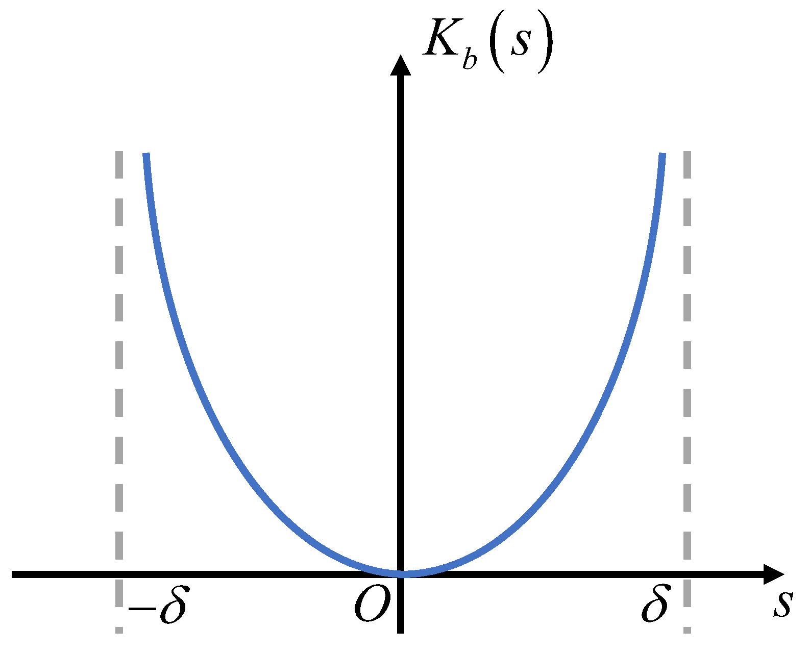
Increasing the value of the parameter ρ tends to accelerate the convergence speed of the error. However, it can also introduce chattering phenomena into the system. On the other hand, the parameter δ determines the convergence domain. A smaller value of δ leads to higher tracking precision. However, if δ is set too small, it may reduce the convergence speed of the system.

4. Experimental Results

The structure diagram depicting the PMSM speed regulation system is presented in Figure 2. In the cascade control loop structure utilized by the controllers, there is a speed loop and two current loops. The motor position is measured using an encoder, while the motor speed is obtained through motor differentiation. In the two current loops, PI controllers are implemented to stabilize the tracking errors of the d-q axes. Both current loops have the same PI parameters, with k p = 200 and k i = 20 .
To evaluate the efficacy of the designed controller, a PMSM experimental platform is deployed on the cSPACE control system, utilizing TMS320F28335 and MATLAB-Simulink R2018b. The platform is illustrated in Figure 3, with the C code conveniently downloaded onto the embedded device through a single keystroke. The PMSM driver consists of a three-phase inverter operating at a switching frequency of 10 kHz. For sampling, a period of 0.001 s is chosen, while the saturation limit for the reference current of the q-axis is set at 10 A. In this experimental setup, a DC motor (DCM) is utilized to generate the load, where the output torque is modulated by adjusting the current. Detailed parameters for the PMSM can be found in Table 1.
The proposed approach employs the control law described by (14), utilizing the sliding surface given in (13), along with adaptive switching gains outlined in (15)–(17). Experimental outcomes are contrasted with those of the conventional TSMC method, as represented by (9). To ensure fairness in the comparison, controllers with identical switching gains are selected, and the parameters are detailed in Table 2.

4.1. Speed Response of Motor Starting

Firstly, the PMSM starts with a reference speed of 1000 rpm. Figure 4a shows the speed response and the q-axis current of both methods. As shown in Figure 4a, both approaches are capable of accurately tracking the step response. However, the proposed approach demonstrates a smaller overshoot and faster settling time compared to the alternative method. Performance indexes for the two methods are presented in Table 3 for further comparison. The proposed method reduces overshoot (OS%) by 6.39% and settling time ( t s ) by 41.0% compared to the TSMC methods. Then, the PMSM is operated under the reference speed of 1500 rpm. Figure 4b demonstrates that these two controllers are still effective in a wide-speed operating environment. Nevertheless, the proposed method has better performance, which reduces OS% by 13.29% and t s by 28.35% compared to the TSMC methods, as shown in Table 3. In both conditions, the proposed method demonstrates faster convergence to a steady state for the current I q compared to the traditional TSMC method used for starting the motor.

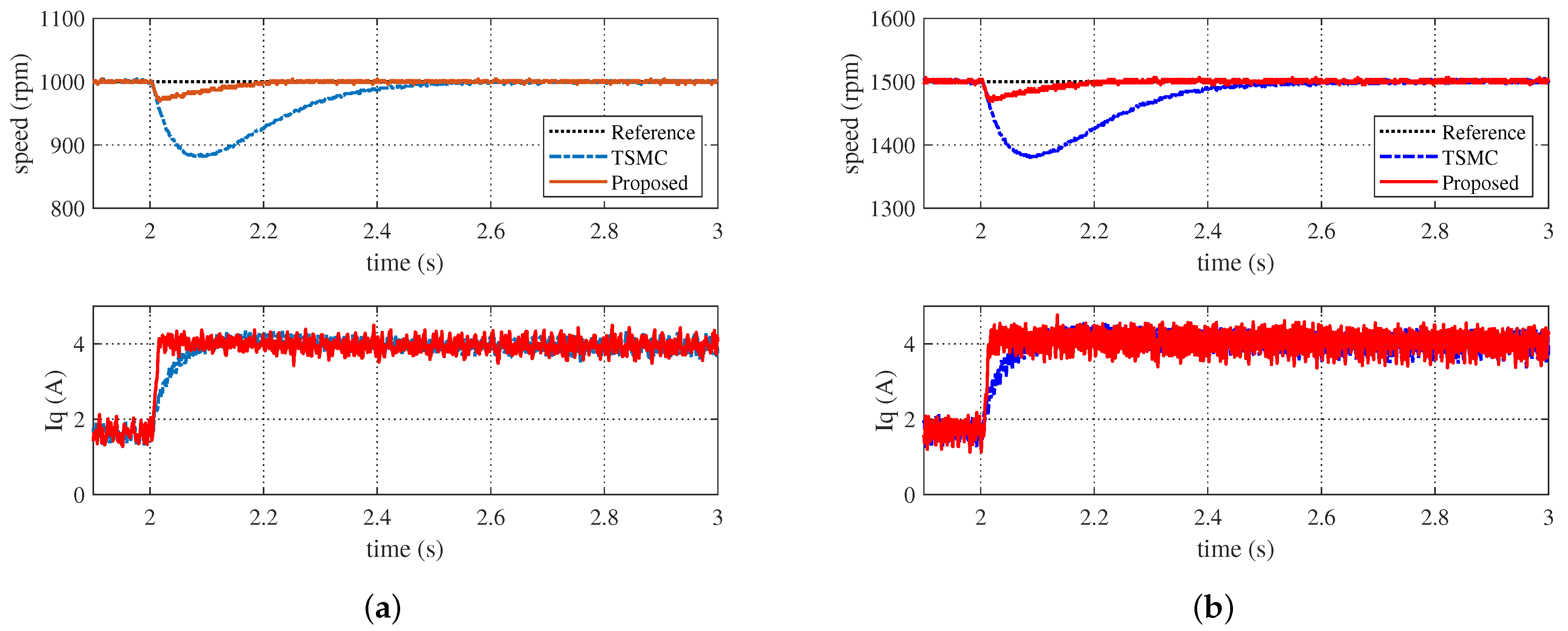
4.2. Speed Response under Sudden Load Torque Changes

At time 2s, the excitation current of the DC motor is adjusted to 3A to generate a 200 mN· m load torque under the 1000 rpm speed. As shown in Figure 5a, the maximum speed decrease with the proposed method is 30.4 rpm, and the speed reduction is reduced by 74.8% compared to 120.4 rpm with the TSMC method. The performance indexes are also given in Table 3. Also, the PMSM is also conducted under the speed of 1500 rpm with the 200 mN· m load torque. As can be seen from Figure 5b, the proposed reduced the speed decrease by 74.4% compared to the traditional TSMC method. Under a sudden load change in both conditions, the proposed method exhibits faster convergence to a steady state for the current I q compared to the traditional TSMC method. The specific performance indexes are also provided in Table 3. The results indicate that the proposed method has superior anti-disturbance ability against external disturbances.

4.3. Speed Response under Variable Parameters

Furthermore, experiments with variable parameters are also conducted to verify the robustness of the proposed controller. In the proposed controller, the change in inertia is achieved by modifying its value, as the rated value of inertia cannot be altered freely; i.e., J n is set as half of the rated value, J n = 1 2 J = 1 2 × 1.23 × 10 4 (kg· m2) at a time of 6 s without load torque. Under the reference speed of 1000 rpm, the results are illustrated in Figure 6a, the maximum speed increase with the TSMC method is 118.0 rpm, while the proposed method is reduced by 76.3% to 28.0 rpm. Similarly, under the reference speed of 1500 rpm, the proposed method reduced the maximum speed increase by 83.0%, as illustrated in Figure 6b. In both conditions, the proposed method achieves faster convergence to a steady state for the current I q compared to the traditional TSMC method when there are sudden parameter variations. Table 3 presents a comparison of the performance indexes between the proposed method and the traditional TSMC method. The proposed method possesses better robustness under parameter variations.

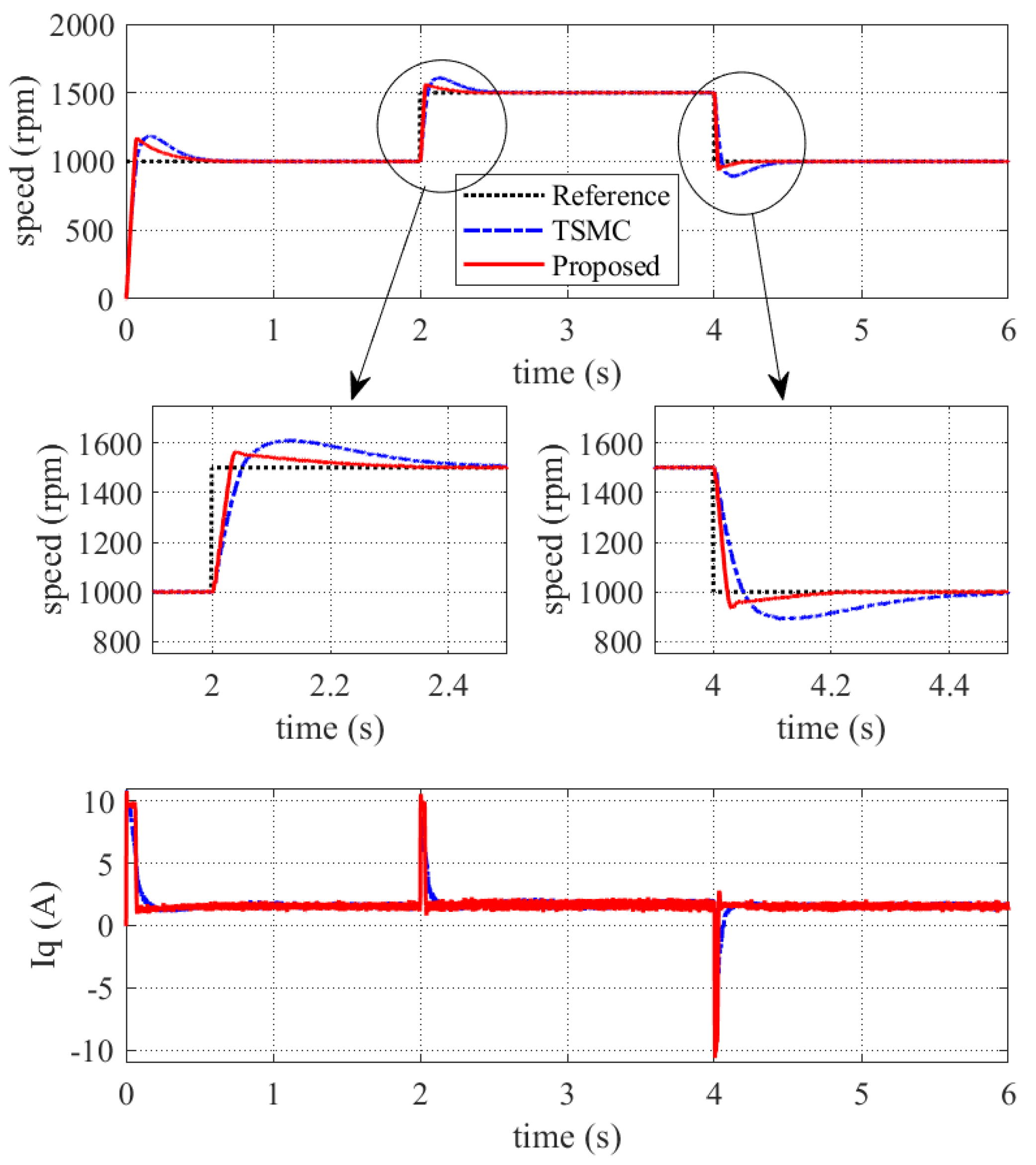
4.4. Variable Speed Response

The experimental results under a variable speed are depicted in Figure 7. In this scenario, the speed range is chosen from 1000 to 1500 rpm without load torque. Across various controllers, the actual speed of the PMSM adeptly and accurately follows the reference speed. However, the proposed method exhibits faster convergence speed and better speed tracking performance. Under sudden speed changes in both conditions, the proposed method achieves faster convergence to a steady state for the current I q compared to the traditional TSMC method.

5. Conclusions

In this paper, a barrier-function-based AFTSMC is applied to the PMSM speed-regulation problem in the presence of parameter variations and external disturbances. A fast-terminal sliding surface is utilized to achieve a faster convergence rate of the system state, leading to better disturbance rejection ability. The barrier function is employed to dynamically modify the amplitude of the control input in response to disturbances on the manifold. This adaptive adjustment prevents the control input from being excessively generated and effectively eliminates chattering, providing smoother and more stable control performance. Furthermore, there is no requirement to know the upper bound of the lumped disturbances like the traditional SMC method, which can be challenging to obtain in practical systems. Experimental results indicate that the proposed method surpasses the traditional TSMC method in terms of tracking performance and disturbance-rejection capability.
In future endeavors, we aim to extend the algorithm to other motor-based systems. Additionally, the control parameters outlined in this study are slightly complex and need slightly high computational complexity, and parametric tunings require intricate trade-off considerations in the actual scenarios. Therefore, further improvements can be made to simplify the control scheme design based on the existing work.

Author Contributions

Conceptualization, X.C. and X.Q.; methodology, X.C.; software, X.C., Z.M., W.L. and H.N.; validation, X.C., Z.M., W.L. and H.N.; formal analysis, X.Q. and C.Y.; investigation, X.C., Z.M., W.L. and H.N.; resources, X.Q., W.L., H.N. and C.Y.; data curation, X.C., Z.M., W.L. and H.N.; writing—original draft preparation, X.C.; writing—review and editing, Z.M., X.Q., W.L. and H.N.; visualization, X.C. and Z.M.; supervision, X.Q. and C.Y.; project administration, X.Q. and C.Y.; funding acquisition, X.C., X.Q. and C.Y. All authors have read and agreed to the published version of the manuscript.

Funding

This research was funded by the National Natural Science Foundation of China, grant number 12103053.

Data Availability Statement

The data presented in this study are available on request from the corresponding authors.

Acknowledgments

Thanks to all the Project team members.

Conflicts of Interest

The authors declare no conflicts of interest.

References

  1. Zhang, D.; Zhang, H.; Li, X.; Zhao, H.; Zhang, Y.; Wang, S.; Ahmad, T.; Liu, T.; Shuang, F.; Wu, T. A PMSM Control System for Electric Vehicle Using Improved Exponential Reaching Law and Proportional Resonance Theory. IEEE Trans. Veh. Technol. 2023, 72, 8566–8578. [Google Scholar] [CrossRef]
  2. Huo, J.; Ji, H.; Yang, P. Research on sensorless control system of permanent magnet synchronous motor for CNC machine tool. In Proceedings of the 2021 40th Chinese Control Conference (CCC), Shanghai, China, 26–28 July 2021; pp. 1592–1595. [Google Scholar]
  3. Ullah, S.; McDonald, S.P.; Martin, R.; Benarous, M.; Atkinson, G.J. A Permanent Magnet Assist, Segmented Rotor, Switched Reluctance Drive for Fault Tolerant Aerospace Applications. IEEE Trans. Ind. Appl. 2019, 55, 298–305. [Google Scholar] [CrossRef]
  4. Bensalem, Y.; Abbassi, A.; Abbassi, R.; Jerbi, H.; Alturki, M.; Albaker, A.; Kouzou, A.; Abdelkrim, M.N. Speed tracking control design of a five-phase PMSM-based electric vehicle: A backstepping active fault-tolerant approach. Electr. Eng. 2022, 104, 2155–2171. [Google Scholar] [CrossRef]
  5. Bensalem, Y.; Abbassi, R.; Jerbi, H. Extended Kalman Filter Based-Sensorless Control of Five-Phase PMSM. In Proceedings of the 2022 5th International Conference on Power Electronics and their Applications (ICPEA), Hail, Saudi Arabia, 29–31 March 2022; pp. 1–7. [Google Scholar]
  6. Bensalem, Y.; Kouzou, A.; Abbassi, R.; Jerbi, H.; Kennel, R.; Abdelrahem, M. Sliding-Mode-Based Current and Speed Sensors Fault Diagnosis for Five-Phase PMSM. Energies 2022, 15, 71. [Google Scholar] [CrossRef]
  7. Lin, X.; Wu, C.; Yao, W.; Liu, Z.; Shen, X.; Xu, R.; Sun, G.; Liu, J. Observer-Based Fixed-Time Control for Permanent-Magnet Synchronous Motors With Parameter Uncertainties. IEEE Trans. Power Electron. 2023, 38, 4335–4344. [Google Scholar] [CrossRef]
  8. Dong, X.; Mao, J.; Yan, Y.; Zhang, C.; Yang, J. Generalized Dynamic Predictive Control for Nonlinear Systems Subject to Mismatched Disturbances With Application to PMSM Drives. IEEE Trans. Ind. Electron. 2024, 71, 954–964. [Google Scholar] [CrossRef]
  9. Yin, Y.; Liu, L.; Vazquez, S.; Xu, R.; Dong, Z.; Liu, J.; Leon, J.L.; Wu, L.; Franquelo, L.G. Disturbance and Uncertainty Attenuation for Speed Regulation of PMSM Servo System Using Adaptive Optimal Control Strategy. IEEE Trans. Transp. Electr. 2023, 9, 3410–3420. [Google Scholar] [CrossRef]
  10. Yu, J.; Shi, P.; Dong, W.; Chen, B.; Lin, C. Neural Network-Based Adaptive Dynamic Surface Control for Permanent Magnet Synchronous Motors. IEEE Trans. Neural Netw. Learn. Syst. 2015, 26, 640–645. [Google Scholar] [CrossRef] [PubMed]
  11. Sandre-Hernandez, O.; de Jesus Rangel-Magdaleno, J.; Morales-Caporal, R. Modified model predictive torque control for a PMSM-drive with torque ripple minimisation. IET Power Electron. 2019, 12, 1033–1042. [Google Scholar] [CrossRef]
  12. Tian, M.; Wang, B.; Yu, Y.; Dong, Q.; Xu, D. Discrete-Time Repetitive Control-Based ADRC for Current Loop Disturbances Suppression of PMSM Drives. IEEE Trans. Ind. Informat. 2022, 18, 3138–3149. [Google Scholar] [CrossRef]
  13. Yu, L.; Huang, J.; Luo, W.; Chang, S.; Sun, H.; Tian, H. Sliding-Mode Control for PMLSM Position Control—A Review. Actuators 2023, 12, 31. [Google Scholar] [CrossRef]
  14. Levant, A. Chattering Analysis. IEEE Trans. Autom. Control 2010, 55, 1380–1389. [Google Scholar] [CrossRef]
  15. Zhihong, M.; Yu, X.H. Terminal sliding mode control of MIMO linear systems. IEEE Trans. Circuits Syst. I Fundam. Theory Appl. 1997, 44, 1065–1070. [Google Scholar] [CrossRef]
  16. Feng, Y.; Yu, X.; Man, Z. Non-singular terminal sliding mode control of rigid manipulators. Automatica 2002, 38, 2159–2167. [Google Scholar] [CrossRef]
  17. Che, X.; Tian, D.; Jia, P.; Gao, Y.; Ren, Y. Terminal Sliding Mode Control with a Novel Reaching Law and Sliding Mode Disturbance Observer for Inertial Stabilization Imaging Sensor. Sensors 2020, 20, 3107. [Google Scholar] [CrossRef] [PubMed]
  18. Sun, X.; Cao, J.; Lei, G.; Guo, Y.; Zhu, J. A Composite Sliding Mode Control for SPMSM Drives Based on a New Hybrid Reaching Law with Disturbance Compensation. IEEE Trans. Transp. Electr. 2021, 7, 1427–1436. [Google Scholar] [CrossRef]
  19. Fan, Y.; Zhang, Q.; Wang, W.; Zhou, X. Speed Regulation System of a Flux-Modulated Permanent-Magnet in-Wheel Motor Based on Sliding Mode Control and Adaptive Notch Filter. IEEE Trans. Energy Convers. 2018, 33, 2183–2190. [Google Scholar] [CrossRef]
  20. Li, S.; Zhou, M.; Yu, X. Design and Implementation of Terminal Sliding Mode Control Method for PMSM Speed Regulation System. IEEE Trans. Ind. Informat. 2013, 9, 1879–1891. [Google Scholar] [CrossRef]
  21. Xu, B.; Zhang, L.; Ji, W. Improved Non-Singular Fast Terminal Sliding Mode Control With Disturbance Observer for PMSM Drives. IEEE Trans. Transp. Electr. 2021, 7, 2753–2762. [Google Scholar] [CrossRef]
  22. Cupertino, F.; Naso, D.; Mininno, E.; Turchiano, B. Sliding-Mode Control With Double Boundary Layer for Robust Compensation of Payload Mass and Friction in Linear Motors. IEEE Trans. Ind. Appl. 2009, 45, 1688–1696. [Google Scholar] [CrossRef]
  23. Fei, J.; Wang, H.; Fang, Y. Novel Neural Network Fractional-Order Sliding-Mode Control With Application to Active Power Filter. IEEE Trans. Syst. Man Cybern. Syst. 2022, 52, 3508–3518. [Google Scholar] [CrossRef]
  24. Labbadi, M.; Cherkaoui, M. Adaptive Fractional-Order Nonsingular Fast Terminal Sliding Mode Based Robust Tracking Control of Quadrotor UAV With Gaussian Random Disturbances and Uncertainties. IEEE Trans. Aerosp. Electron. Syst. 2021, 57, 2265–2277. [Google Scholar] [CrossRef]
  25. Chalanga, A.; Kamal, S.; Fridman, L.M.; Bandyopadhyay, B.; Moreno, J.A. Implementation of Super-Twisting Control: Super-Twisting and Higher Order Sliding-Mode Observer-Based Approaches. IEEE Trans. Ind. Electron. 2016, 63, 3677–3685. [Google Scholar] [CrossRef]
  26. Balogoun, I.; Marx, S.; Liard, T.; Plestan, F. Super-Twisting Sliding Mode Control for the Stabilization of a Linear Hyperbolic System. IEEE Control. Syst. Lett. 2023, 7, 1–6. [Google Scholar] [CrossRef]
  27. Huang, Y.; Kuo, T.; Chang, S. Adaptive Sliding-Mode Control for NonlinearSystems With Uncertain Parameters. IEEE Trans. Syst. Man Cybern. Syst. 2008, 38, 534–539. [Google Scholar] [CrossRef] [PubMed]
  28. Baek, J.; Jin, M.; Han, S. A New Adaptive Sliding-Mode Control Scheme for Application to Robot Manipulators. IEEE Trans. Ind. Electron. 2016, 63, 3628–3637. [Google Scholar] [CrossRef]
  29. Obeid, H.; Fridman, L.M.; Laghrouche, S.; Harmouche, M. Barrier function-based adaptive sliding mode control. Automatica 2018, 93, 540–544. [Google Scholar] [CrossRef]
  30. Chen, L.; Jin, Z.; Shao, K.; Harmouche, M. Sensorless Fixed-Time Sliding Mode Control of PMSM Based on Barrier Function Adaptive Super-Twisting Observer. IEEE Trans. Power Electron. 2023, 39, 3037–3051. [Google Scholar] [CrossRef]
  31. Dai, B.; Wang, Z. Disturbance Observer-Based Sliding Mode Control Using Barrier Function for Output Speed Fluctuation Constraints of PMSM. IEEE Trans. Energy Convers. 2024, 1–10. [Google Scholar] [CrossRef]
  32. Deng, Y.; Wang, J.; Li, H.; Liu, J.; Tian, D. Adaptive sliding mode current control with sliding mode disturbance observer for PMSM drives. ISA Trans. 2019, 88, 113–126. [Google Scholar] [CrossRef]
  33. Yu, S.; Yu, X.; Shirinzadeh, B.; Man, Z. Continuous finite-time control for robotic manipulators with terminal sliding mode. Automatica 2005, 41, 1957–1964. [Google Scholar] [CrossRef]
Figure 1. Illustration of barrier function K b ( s ) with respect to sliding variable s ( δ , δ ) .
Electronics 13 01091 g001
Figure 2. The structure diagram of the speed control system of PMSM.
Electronics 13 01091 g002
Figure 3. Experimental setup.
Electronics 13 01091 g003
Figure 4. Speed response and q-axis current of motor starting: (a) 1000 rpm; (b) 1500 rpm.
Electronics 13 01091 g004
Figure 5. Speed response of and q-axis current under load torque: (a) 1000 rpm; (b) 1500 rpm.
Electronics 13 01091 g005
Figure 6. Speed response and q-axis current under parameter variation J n = 1 2 J : (a) 1000 rpm; (b) 1500 rpm.
Electronics 13 01091 g006
Figure 7. Variable speed response and q-axis current.
Electronics 13 01091 g007
Table 1. Parameters of PMSM.
DescriptionValue
moment of inertia 1.23 × 10 4 (kg · m2)
frictional coefficient 3.0134 × 10 4 (N·m·s/rad)
rated speed3000 (r/min)
rated torque1.27 (N·m)
stator resistance0.125 ( Ω )
stator inductance0.25 (mH)
rotor flux0.01325 (Wb)
pole pairs4
Table 2. Experimental parameters of different control methods.
ControllerParameters
TSMC β = 80 ,   λ = 0.5 ,   k 1 = 10 ,   k 2 = 5
the proposed α = 40 ,   β = 40 ,   λ = 0.5 ,   k 2 = 5 ,   ρ = 1 ,   δ = 0.01
Table 3. Comparison of experimental performance indices with different control methods.
ControllerOS% t s (s)Speed Decrease with Load Torque (rpm)Speed Decrease with Parameter Variation (rpm)
TSMC under 1000 rpm18.160.497120.4118.0
the proposed under 1000 rpm17.000.29330.428.0
TSMC under 1500 rpm27.530.536121.0312.0
the proposed under 1500 rpm23.870.38431.053.0
Disclaimer/Publisher’s Note: The statements, opinions and data contained in all publications are solely those of the individual author(s) and contributor(s) and not of MDPI and/or the editor(s). MDPI and/or the editor(s) disclaim responsibility for any injury to people or property resulting from any ideas, methods, instructions or products referred to in the content.

