Article

A Novel Series 24-Pulse Rectifier Operating in Low Harmonic State Based on Auxiliary Passive Injection at DC Side

1
School of Automation and Electrical Engineering, Lanzhou Jiaotong University, Lanzhou 730070, China
2
Key Laboratory of Opto-Technology and Intelligent Control Ministry of Education, Lanzhou Jiaotong University, Lanzhou 730070, China
3
China Railway Lanzhou Bureau Group Co., Ltd., Power Supply Department, Lanzhou 730070, China
*
Author to whom correspondence should be addressed.
Electronics 2024, 13(6), 1160; https://doi.org/10.3390/electronics13061160
Submission received: 4 February 2024 / Revised: 16 March 2024 / Accepted: 20 March 2024 / Published: 21 March 2024
(This article belongs to the Special Issue Advanced Technologies in Power Electronics and Electric Drives)

Abstract

:
To reduce the current harmonics on the input side of a multi-pulse rectifier, this paper proposes a low harmonic current source series multi-pulse rectifier based on an auxiliary passive injection circuit at the DC side. The rectifier only needs to add an auxiliary passive injection circuit on the DC side of the series 12-pulse rectifier, which can change its AC input voltage from 12-step waves to 24-step waves. We analyzed the working mode of the rectifier, optimized the optimal turn ratio of the injection transformer from the perspective of minimizing the total harmonic distortion (THD) value of the input voltage on the AC side, and analyzed the diode open circuit fault in the auxiliary passive injection circuit. Test verification shows that, after using the passive harmonic injection circuit, the THD value of the input voltage of the AC side of the rectifier is reduced from 14.03% to 4.86%. The THD value of the input current is reduced from 5.30% to 2.16%. The input power factor has been increased from 98.86% to 99.83%, and the power quality has been improved.

1. Introduction

In the industrial field, multi-pulse rectifiers are widely used due to their simple structure, high reliability, and system robustness [1,2,3]. However, due to the use of a large number of nonlinear devices, many harmonics are generated, resulting in harmonic pollution of the utility grid [4,5,6]. How to reduce the harmonic pollution generated by multi-pulse rectifiers has therefore become an important research topic at present [7,8,9,10].
Multi-pulse rectifiers are often used as current converter units and are categorized into two main types—series and parallel—on the basis of the different methods for connecting rectifier bridges [11,12]. Parallel rectifiers have problems such as unbalanced output current, complex autotransformer winding structure, and no isolated DC or AC sides, which greatly limits their application [13,14,15]. Series rectifiers have the advantages of simple circuit structure and strong overload capacity. They are often used in high-power rectification applications [16]. Among them, the series 12-pulse rectifier is commonly used because of its simple winding configuration, but its input current still contains a large number of 12n ± 1st order harmonics. The total harmonic distortion value of the input voltage is greater than 10%. Generally speaking, the total harmonic distortion rate of the voltage in industrial and commercial power systems should not exceed 5%. Therefore, the series 12 pulse rectifier cannot meet the requirements of the IEEE519 harmonic standard [17]. In order to effectively suppress the input current harmonics of the series 12-pulse rectifier, several methods have been proposed. The first method is to install passive and active filters on its AC side to inject current to compensate for the harmonics input current of the rectifier [18]. The passive filters are easy to implement and cost-effective, but can only compensate some low harmonics. The source filter has a good harmonic inhibitory effect, but its control is complex and not cost-effective. The second method is to reduce the input current harmonic by introducing active devices on the DC side of the 12-pulse rectifier in series [19]. Literature [20] used a multi-pulse rectifier based on an active PWM current source and, by adding a half-bridge inverter power supply with less power, the generated frequency-specific triangular current can be injected into the DC side, which serves the purpose of eliminating the harmonics of the grid current. These methods can effectively reduce the input current harmony, but the current stress and switching loss of the source switch are large. The third method is to increase the number of pulses in the multi-pulse rectifier, which is obtained in the literature [21,22,23] by further increasing the number of phase shifter transformer voltage phases. The input current THD is reduced by half compared to the series 12-pulse rectifier. However, the phase shifter transformer structure is becoming more and more complex, which is not favorable for transformer manufacturing. In addition, multiple winding interactions increase material utilization. Literature [24,25,26,27,28] used auxiliary non-passive circuits on the DC side of the rectifier for harmonic suppression without increasing the structural complexity of the phase-shifted transformer; however, the theoretical value of the voltage harmonic distortion rate on the AC side is high and there is still room for improvement. Literature [29] came up with a series 24-pulse rectifier based on the DC-side passive voltage harmonic injection method. The rectifier can produce the DC side of the rectifier by adding the injection circuit to the DC side and through the injecting transformer, thereby generating six times the harmonic power grid voltage frequency, meaning the rectifier can change the input voltage from the 12th stage to 24. Nevertheless, the injection transformer contains a central tap and has a more complex structure.
To sum up, this paper proposes a current-source type series 24-pulse rectifier based on auxiliary passive injection at the DC side. This method injects a specific frequency voltage into the rectifier through an auxiliary circuit so that the input voltage is changed from a 12-step to a 24-step wave, which greatly reduces the harmonic content of the input current on the AC side and improves the power factor. The validation results show that, after using the auxiliary passive harmonic injection circuit, the THD value of the rectifier input current is only 2.16%, which has good harmonic suppression capability. The input power factor rises to 99.83%, which improves the power quality. The system robustness is enhanced, and when the auxiliary passive harmonic injection circuit fails, the rectifier’s rectification effect is still better than that of the traditional 12-pulse rectifier, and the anti-interference capability is strong.

2. Materials and Methods

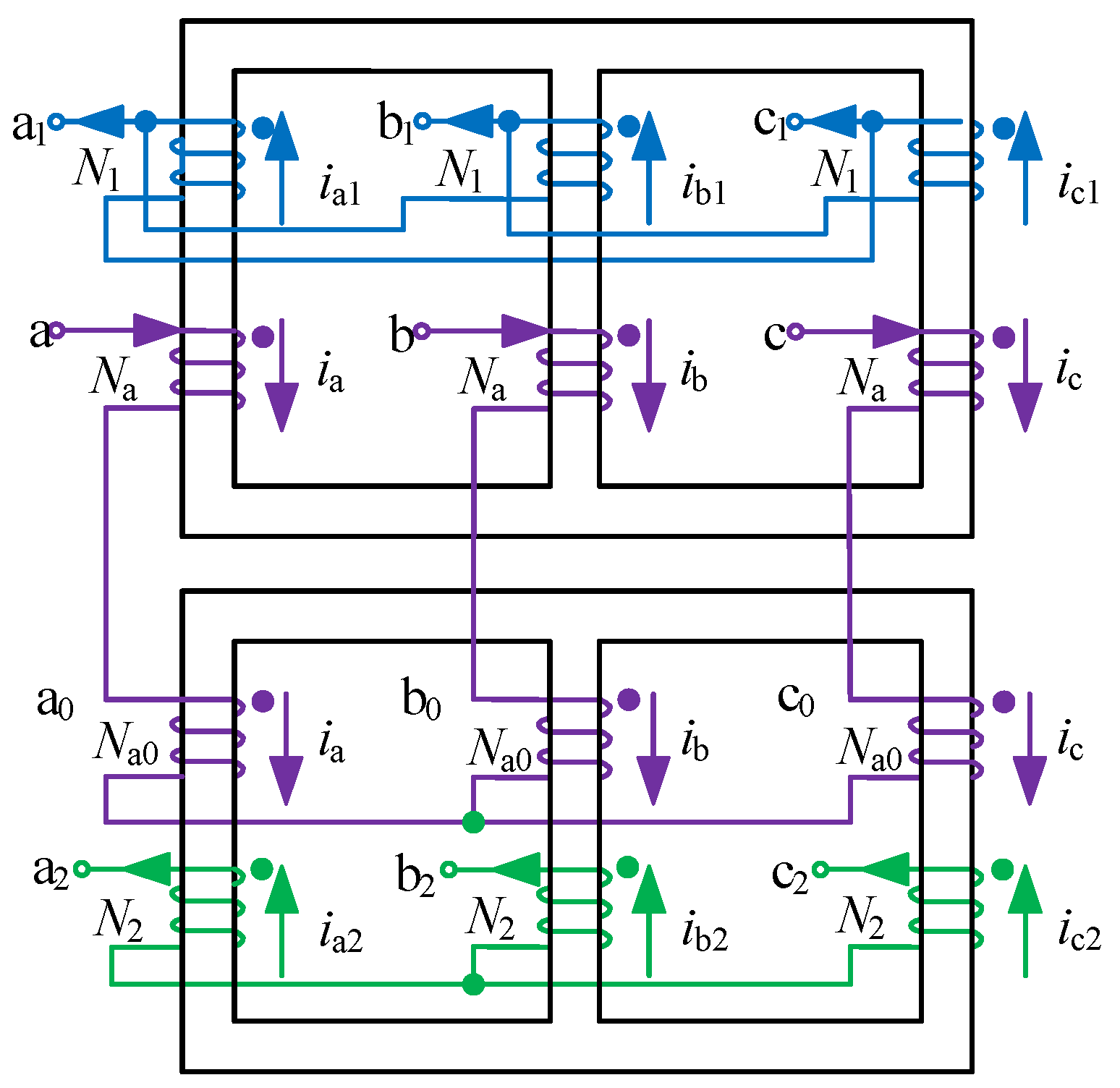
2.1. Topology Analysis

Figure 1 shows the topology of the current-source type series multi-pulse wave rectifier, based on an auxiliary passive injection circuit proposed in this paper. In Figure 1, the power supply is a set of three-phase AC voltage sources of phase differences 120°, denoted as Ua, Ub, and Uc. The inductance Ls on the AC-side are connected in series with the voltage sources, and the rectifier can be equated to a current-source-type converter. A large capacitance filters the DC-side to satisfy the C1 = C2= C, and the load voltage, denoted as u0, has a very small ripple, which can be equated to a constant voltage load.
An auxiliary passive harmonic injection circuit (APHIC) is connected to a series 12-pulse rectifier. The proposed 24-pulse rectifier consists of a series 12-pulse rectifier and an APHIC, which includes an auxiliary single-phase transformer (AST) and an auxiliary single-phase full-bridge rectifier (ASFR). The ASFR consists of diodes D1, D2, D3, and D4 in parallel, and its output is connected in parallel with the three-phase rectifier bridge Rec1, which is a unique structure that helps to reduce the voltage and current stresses on the ASFR. The ASFR extracts a specific square wave voltage from the DC side of the rectifier and injects it into the output of the three-phase rectifier bridges Rec1 and Rec2, to modulate and increase their output voltage states. Under the action of APHIC, the number of output voltage levels increased, which increases the net-side input voltage waveform to a 24-step waveform by the transformer phase-shifted superposition principle.
Figure 2 shows the winding diagram of a phase-shifting transformer. In the figure, the two three-phase transformers are star-delta and star-star structures, respectively. The number of turns in the primary winding of the transformer are recorded as Na and Na0, and the number of turns in the secondary winding are N1 and N2. The turn ratio relationship in Figure 2 satisfies k 1 = N 1 : N a = 3 : 1 , k 2 = N 2 : N a 0 = 1 : 1 .
The output end of the phase-shifting transformer is connected to the two three-phase rectifier bridges, respectively, and the input end is connected to the inductance. The series structure of the two three-phase rectification bridges solves the problem of the imbalance of current and doubles the output voltage.
Figure 3 shows the AST winding structure of an auxiliary single-phase transformer. The number of turns of the primary and secondary side windings are Ns and Nq, respectively, and the corresponding terminal voltages and currents are us, uq, and is, iq, respectively. The primary and secondary winding turns ratio is defined as m and is expressed as follows:
m = N s N q = u s u q

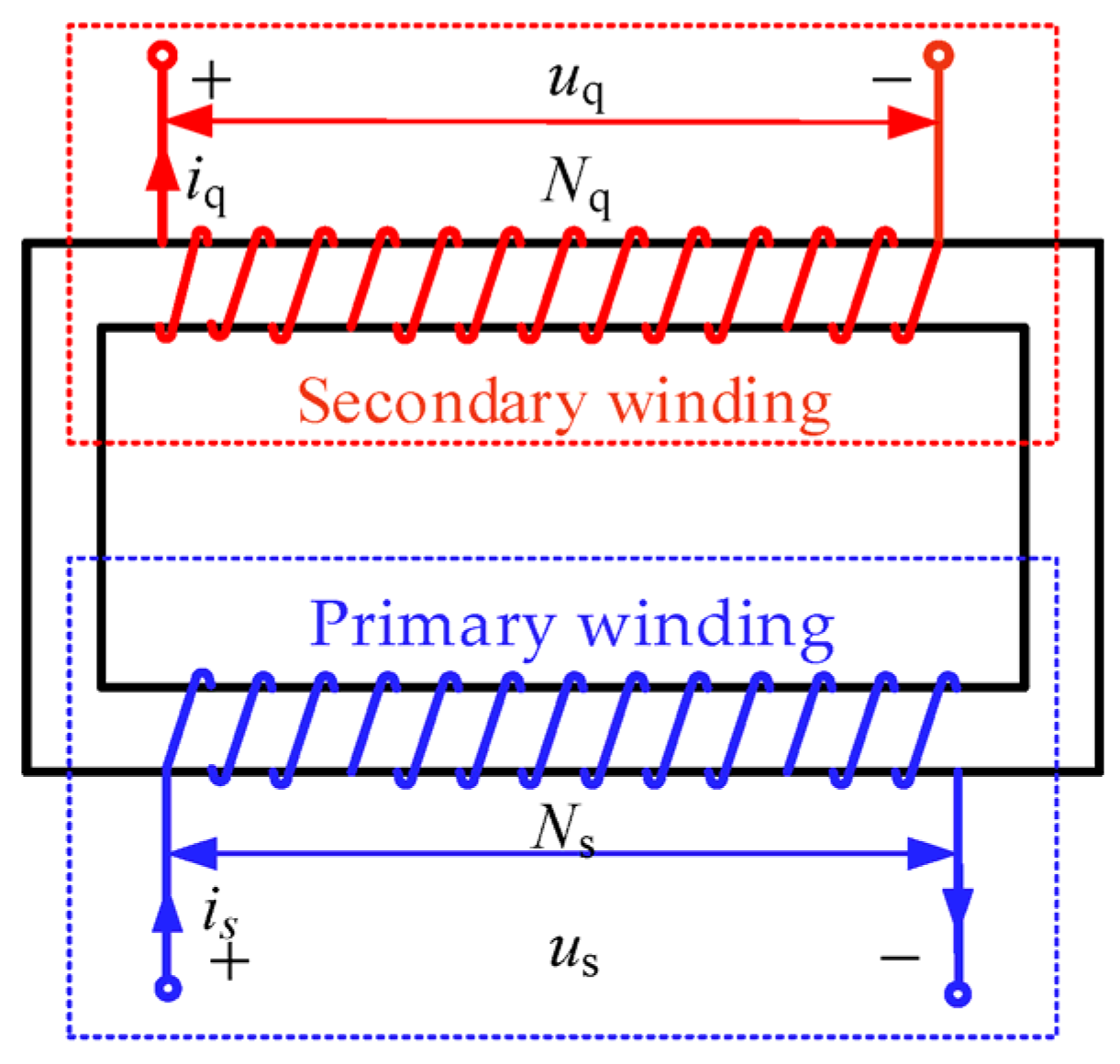
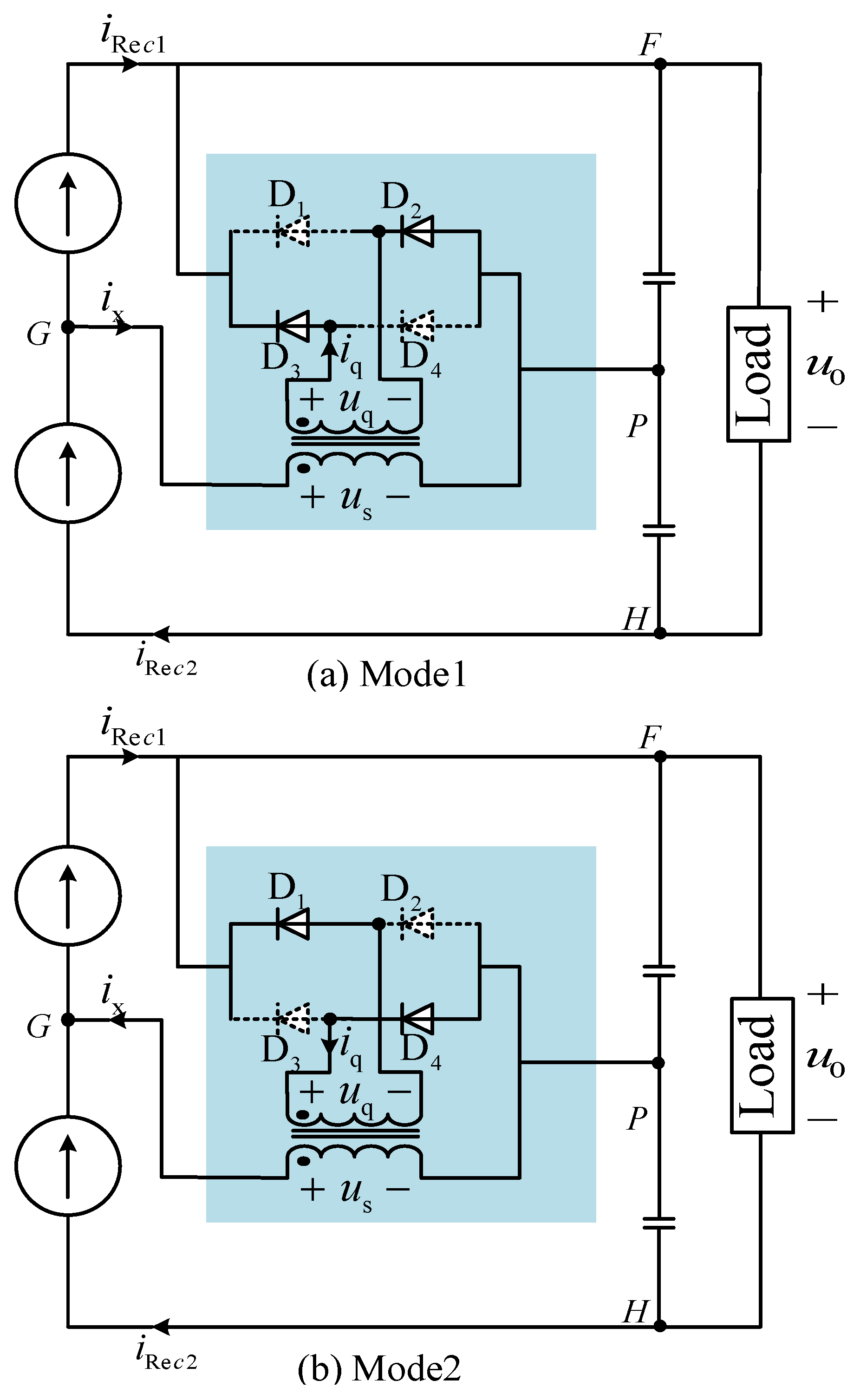
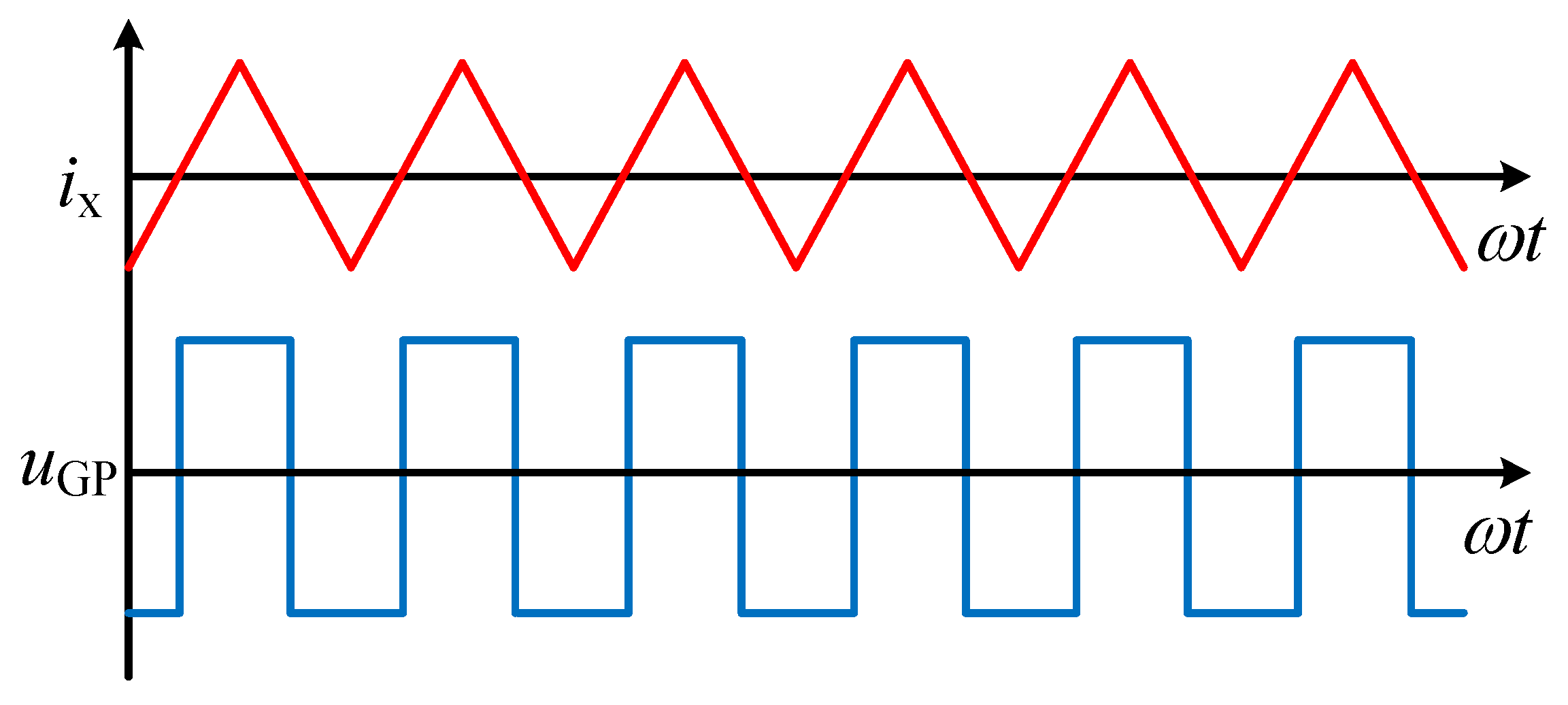
2.2. Operating Modal Analysis of APHIC

The 24-pulse rectifier mentioned in this paper is a current source type converter, so two sets of three-phase rectifier bridges can be equivalently replaced by current source; according to the turn ratio relationship and connection method of the transformer, the two current sources are a 6-pulse current with the same average value and the instantaneous phase difference of 30° (denoted as iRec1, iRec2), as shown in Figure 4.
According to Figure 1 and Figure 4, it can be seen that the primary winding current ix of AST is 6 times the frequency of AC. The analytical process considers the diode conduction loss, and records the forward conduction voltage drop of the diode as Ud. Equating the two three-phase rectifier bridges as two current sources, two modes of operation of the passive harmonic injection circuit can be obtained. The circuit diagrams in different modes are shown in Figure 5.
Mode 1: In Figure 5a, ix > 0 when iRec1 < iRec2 is obtained according to Kirchhoff’s current law (KCL), it can be obtained that
i Re c 2 = i Re c 1 + i X
Work mode 1 under ix and us associated, then us > 0, uq > 0, diodes D1 and D4 off, iD1 = iD4 = 0, D2, and D3 conduction, iD2 = iD3 > 0, at this time passive harmonics injected into the primary side of the transformer winding voltage uGP can be shown as
u G P = m u q = m ( 1 2 u 0 + 2 U d )
As the current difference between iRec1 and iRec2 decreases, ix decreases to zero, operating mode 1 ends, and the rectifier’s operating state switches to operating mode 2.
Mode 2: In Figure 5b, ix < 0 when iRec1 > iRec2 is obtained according to Kirchhoff’s current law (KCL), it can be obtained that
i Re c 1 = i Re c 2 + i X
The ix direction is non-associated with us under operating mode 2, then us < 0, uq < 0, diodes D1 and D4 conduct, iD1 = iD4 > 0, D2 and D3 turn off, iD2 = iD3 = 0. At this time, passive harmonics injected into the transformer primary-side winding voltage uGP can be expressed as
u G P = m u q = m ( 1 2 u 0 + 2 U d )
As the current difference between iRec1 and iRec2 peaks, ix continues to decrease, operating mode 2 ends, and the rectifier operating state cycle switches to operating mode 1. As a result, the passive harmonics injected into the primary side of the transformer will generate a square wave voltage at 6 times the grid voltage frequency with an amplitude of uGP, as shown in Figure 6.

2.3. Operating Characteristics Analysis of Rectifier

Based on the above analysis of the operating modes of the passive harmonic injection circuit, the formation and theoretical values of the 24-step waveforms of the input voltages (uan, ubn, ucn) on the AC side are given here, and the optimum turn ratios of the passive harmonic injection transformer are designed accordingly. For simplicity, the 24-step voltage formation process of uan in the case of mode 1 is analyzed separately.

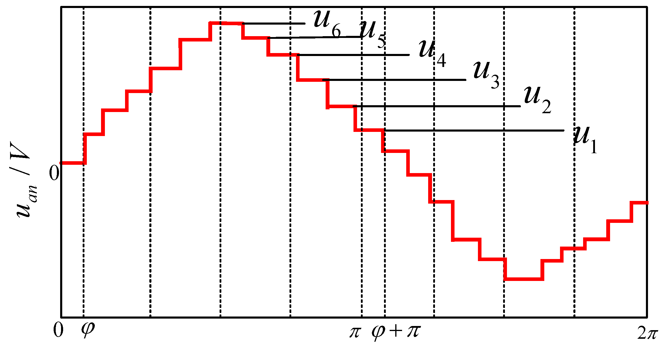
2.3.1. 24-Step Voltage Formation Process

The midpoint P of the capacitor on the DC side is selected as the reference point. The two sets of three-phase windings with the rectifier bridges Rec1 and Rec2 are noted as A1, B1, C1, and A2, B2, C2, and the voltages between them and the reference points P and G are noted as uA1p, uB1p, uC1p and uA2p, uB2p, uC2p, uA2G, uB2G, uC2G, respectively. According to the phase-shifted transformer in Figure 1 and the winding structure and turns ratio relationship, the following relationship exists between its phase shifter transformer input voltage uan and the phase shifter transformer secondary side voltage (uA1C1, uA2n2)
u an = u aa 0 + u a 0 n = 1 3 u A 1 C 1 + u A 2 n 2
From the above Equation (6), it can be seen that the input voltage uan of the phase shifter transformer can be obtained from the phase shifter transformer secondary side voltages uA1C1 and uA2n2; therefore, only the secondary side voltages uA1C1 and uA2n2 are required. From Figure 1, the following can be obtained
u A 2 P = u A 2 G + u GP = m 2 u 0 + ( 1 + 2 m ) U d u B 2 P = u PH + u HB 2 = 1 2 u 0 + U d u C 2 P = u C 2 G + u GP = m 2 u 0 + ( 1 + 2 m ) U d
The voltages between the coupling points A2, B2, C2, and the neutral point n2 of the star-type three-phase winding are denoted as uA2n2, uB2n2, and uC2n2, respectively, and satisfy the following relationship in the equilibrium state
u A 2 n 2 + u B 2 n 2 + u C 2 n 2 = 0
From Kirchhoff’s voltage law, we get
u A 2 n 2 = u A 2 P u n 2 P u B 2 n 2 = u B 2 P u n 2 P u C 2 n 2 = u C 2 P u n 2 P
Combining Equations (7)–(9), it is obtained that
u n 2 p = u A 2 P + u B 2 P + u C 2 P 3 = 2 m + 1 6 u 0 + 4 m + 3 3 U d
Substituting Equation (10) into Equation (9) yields
u A 2 n 2 = m 1 6 u 0 + 2 m 3 U d
According to the working principle of the circuit, the following can be obtained
u A 1 p = u C 1 p = u 0 2 U d
From Kirchhoff’s voltage law, it can be expressed that
u A 1 C 1 = u A 1 p u C 1 p = 0
Finally, according to Kirchhoff’s voltage law and electromagnetic induction principle, the input voltage uan on the AC side can be obtained by bringing (11) and (13) into (6), as shown in Equation (14).
u an = u aa 0 + u a 0 n = 1 3 u A 1 C 1 + u A 2 n 2 = m 1 6 u 0 + 2 m 3 U d
Similarly, the stepped wave value of uan in other modes can be obtained. Figure 7 shows the theoretical waveform of the AC input voltage uan in one power supply cycle, and the level values of each step are expressed in Table 1.

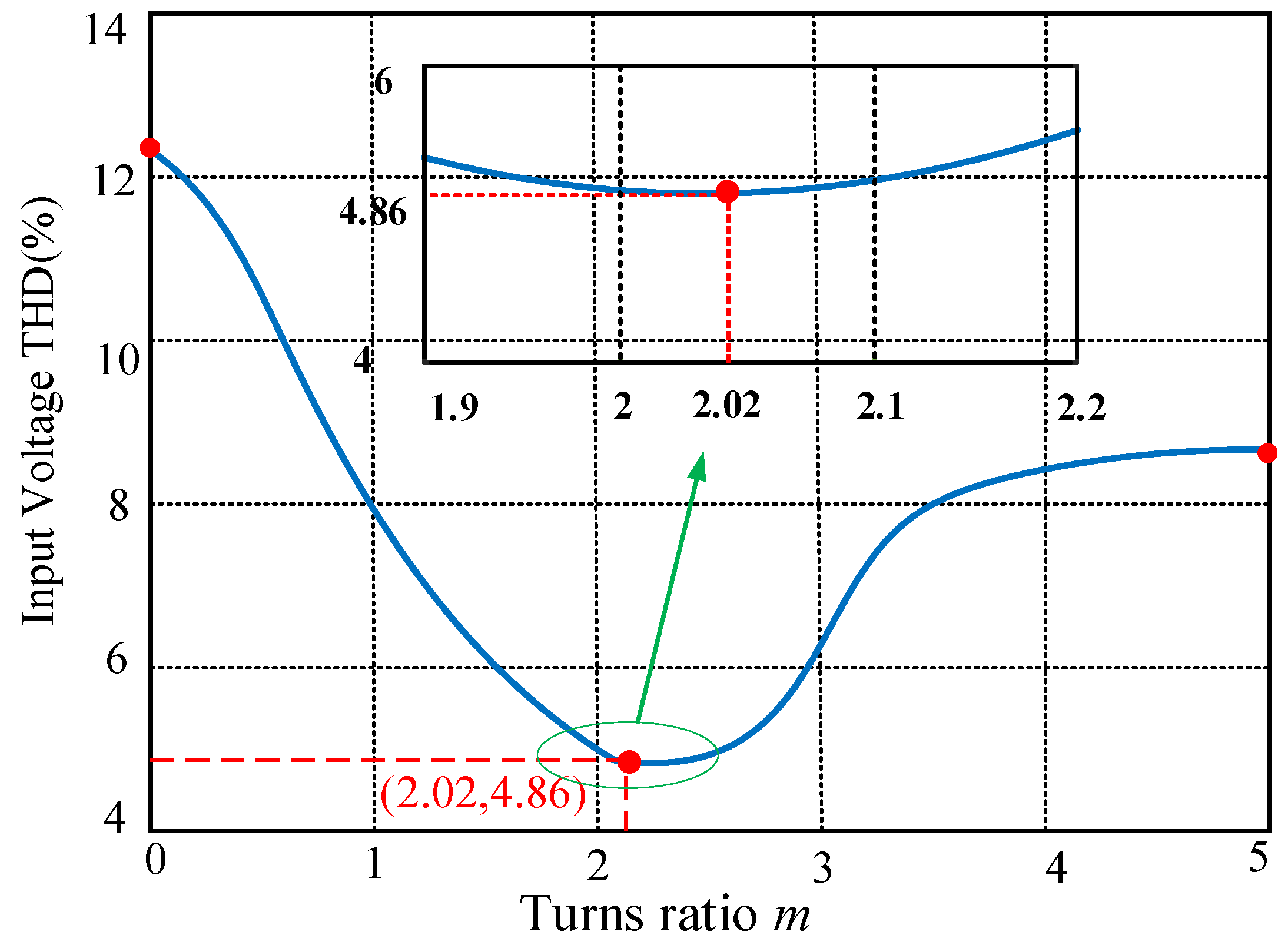
2.3.2. Optimal Turns Ratio Design of AST

From Figure 1 and Figure 5, it can be seen that the operating modes of APHIC are determined by the injected current ix and the AST primary voltage, which depends on its turn ratio and secondary voltage. To ensure that the rectifier system proposed in this paper operates in a 24-pulse wave rectification state, this part of the AST turn ratio is optimized and designed.
To minimize the total harmonics distortion of input voltage on the AC side, the value of uan is related to the turn ratio m of the AST from the expression of uan in Table 1.
Combining Figure 7 and Table 1, the RMS value Uan of the input voltage uan on the AC side, and the fundamental voltage amplitude US, can be calculated
U an = 1 T 0 T u an 2 d t
U s = 4 π [ ( 3 2 3 ) u 0 + ( 4 2 3 ) U d + 2 ( 6 3 ) u 0 + U d m ]
The input voltage THD on the AC side can be expressed as TV, and
T V = 2 U an 2 U s 2 U s
The total harmonics distortion value of the input voltage uan at the AC side can be obtained by substituting the expressions of Uan as well as the US into Equation (17). The variation of the THD value of uan with AST turns ratio m is shown in Figure 8.

3. Verification and Analysis

In order to verify the above theoretical analysis, this section builds the rectifier model proposed in this paper on Matlab 2020b/Simulink software, and simulation verification and analysis are carried out. It is tested in the Shanghai of China Far Wide Energy Starsim Hardware In the Loop (HIL) test system, which is shown in Figure 9 as the HIL test platform. The simulation and experimental parameters of the proposed rectifier are shown in Table 2.

3.1. Verification of Rectifier Operating State under Resistive Load

The waveforms and their spectrum of the input voltage uan on the AC side of the rectifier when the APHIC is not operating and when it is operating under resistive load are given in Figure 10. It can be seen that the rectifier operates in the 12-pulse rectifier state when the APHIC does not work, and the total harmonics distortion value of the input voltage is 14.03%, which contains a great number of 12n ± 1th harmonics. When the APHIC works, the number of input voltage steps increases from 12 to 24, and the rectifier operates in the 24-pulse state, and the THD value of the input voltage at the AC side of the rectifier is reduced from 14.03% to 4.86%. It can be seen that the input voltage uan under the action of the APHIC contains the 24n ± 1th harmonic, which is in line with the operating characteristics of the 24-pulse rectifier and is consistent with the results of the theoretical analysis.
The waveforms of the input current ia, and the AC side of the rectifier and its spectrum when the APHIC is not operating and when it is operating are shown in Figure 11. It can be seen that, after accessing the auxiliary passive harmonic injection circuit, the input current of the rectifier is closer to a sinusoidal waveform, the THD value is reduced from 5.3% to 2.16%, and the harmonic suppression capability is improved.
The waveforms of voltage uGP and current ix of the AST primary winding are shown in Figure 12. In the figure, the AST primary winding voltage uGP is a 6-fold square wave, the primary current ix = iRECI2iREC1, the current waveform is a triangular wave, and there are two operating modes of the APHIC.
The waveforms of the rectifier load voltage u0, as well as the load current i0, are given in Figure 13. The figure shows that the ripples of both the load voltage and load current are tiny, the current i0 is 9.3 A, the voltage u0 is 463.7 V, and the load power is about 4312 W. Due to the influence of the large capacitance on the DC side, the load current and voltage are kept constant. The input power factor of this rectifier is improved from 98.86% to 99.83% after adding an auxiliary passive harmonic injection circuit. Therefore, the rectifier proposed in this paper can improve the power quality with a significant harmonic suppression effect.

3.2. Verification of Rectifier Operating State under Resistive Inductive Load

Figure 14a indicates the waveform of the input voltage on the AC side of the rectifier under resistive inductive load conditions. The AC-measured input voltage is a 24-step waveform with a THD value of 4.88%. The simulation results of load current i0 and load voltage u0 under resistive inductive conditions are shown in Figure 14b.
As seen in Figure 14, the basic characteristics of the proposed rectifier remain consistent when the load is a resistive load and a resistive inductive load, indicating strong load applicability of the rectifier.

3.3. Analysis of Rectifier Fault Tolerance during APHIC Diode Open-Circuit Failure

In this section, open-circuit faults of diodes in passive harmonic injection circuits are analyzed as well as simulated and verified. They are divided into the following two fault states: (1) open-circuit failure of any diode D1–D4 (D1 is analyzed as an example); and (2) open-circuit failure of all diodes D1, D2, D3, and D4.
Figure 15 shows the plots of uGP for two open-circuit fault statuses, respectively. Figure 16 gives the waveforms of the input voltage uan on the AC side of the rectifier under two fault conditions. From the figure, it can be seen that in the fault (1) state, the rectifier input voltage is approximated as an 18-step wave with a THD value of 8.21%. In the fault (2) state, the rectifier input voltage is restored as a 12-step wave, but its THD value is 10.55%, which is lower than the THD value of the traditional 12-pulse rectifier input voltage.
Therefore, the rectifier proposed in this paper has good fault tolerance in the state of a diode open circuit fault, and its robustness is also stronger, making it more suitable for medium and high voltage situations.

3.4. Comparison of Different Harmonic Suppression Methods

In this part, the proposed harmonic suppression method is compared and analyzed with other rectifiers with different harmonic suppression methods on the DC side, in terms of comprehensive harmonic suppression performance, number of auxiliary diodes, and type of injection transformer. The comparison of key parameters under different harmonic suppression methods of the rectifier is given in Table 3.
Compared with the rectifier without an injection circuit, the rectifier proposed in this article has better harmonic suppression ability. The input voltage on the AC side has changed from 12-step waves to 24-step waves, which greatly reduces the THD value of the input voltage and current on the grid side. Compared with the harmonic suppression square wave in literature [28], the number of auxiliary diodes used and the type of injection transformer are the same. Still, the proposed rectifier in this paper improves the power quality, reduces the rectifier AC-side harmonics, and doubles the output voltage, which is suitable for medium- and high-voltage situations. In addition, the proposed harmonic suppression method is more robust; even if the auxiliary diode has an open-circuit failure, it can still ensure that the rectifier system works normally with high performance, which is not available in the method proposed in the literature [28]. Compared with the harmonic suppression method in the literature [29], the proposed rectifier has the same harmonic suppression capability, and both of them can make the rectifier’s AC-measured voltage pulse number increase from 12 to 24. However, the structure of the proposed scheme and the harmonic suppression circuits of the above two schemes are different, and it is important to note that the use of an auxiliary transformer with no center tap in this paper reduces the size of the system, and it is makes the rectifier’s production and manufacture easier, and has a lower input current THD value.
Comprehensively analyzing the above, the rectifier proposed in this article has a simple structure, with low harmonics, low complexity, high-output voltage, and other characteristics, which make it suitable for multi-electrical aircraft and other aviation current converter occasions. Compared with other rectifiers, the rectifier proposed in this article performs better, which lays the foundation for exploring and designing harmonic suppression scheme with higher cost-effectiveness.

4. Conclusions

In order to improve the power quality of the series 12-pulse rectifier, a current source type series 24-pulse rectifier based on auxiliary passive injection on the DC side is proposed in this article. The relevant conclusions of this paper are as follows:
(1)
The realization of this rectifier relies on the auxiliary passive harmonic injection circuit, including the passive harmonic injection auxiliary transformer and the auxiliary single-phase full bridge rectifier circuit; the rectifiers all use passive devices, which are simple in structure, strong in anti-jamming capability, and easy to realize.
(2)
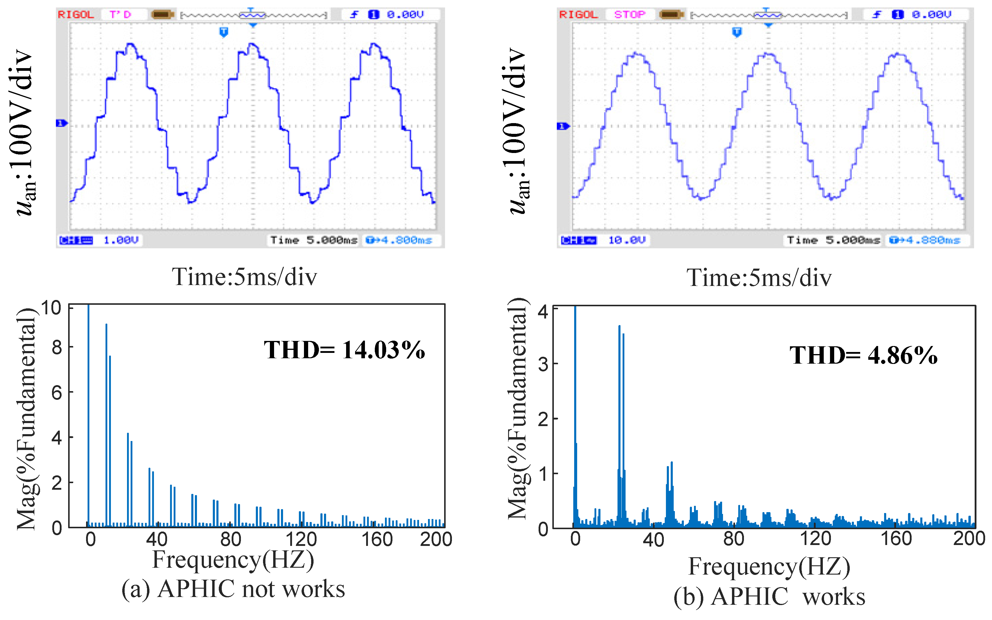
Compared with the 12-pulse rectifier, the proposed rectifier can multiply the number of pulses of the input voltage from 12 pulses to 24 pulses, the THD value of the input voltage is reduced from 14.03% to 4.86%, and the waveform of the input voltage is closer to a sinusoidal waveform. The THD value of the input current on the AC side is reduced from 5.30% to 2.16%, which is nearly sinusoidalized. The harmonic suppression ability of the rectifier has been greatly improved. When the turn ratio of the passive harmonic injection transformer is 2.02, the input power factor is increased from 98.86% to 99.83%, which reduces the pollution of the rectifier reactive current on the grid and significantly improves the power quality.
(3)
Robustness. The proposed rectifier in the auxiliary diode open circuit fault case has a good system fault tolerance in this state; although it will have a certain impact on the AC side power quality, it can still realize the rectification function, and the rectification effect is better than that of the series 12-pulse wave rectifier.

Author Contributions

Conceptualization, X.C.; methodology, T.B.; software, J.G.; validation, Y.W. and T.B.; formal analysis, X.M. and Z.C.; data curation, Y.W.; writing—original draft preparation, T.B.; writing review and editing, Y.W.; visualization, X.C. All authors have read and agreed to the published version of the manuscript.

Funding

This research was funded by the National Natural Science Foundation of China (52067013, 52367009) and the Natural Science Key Foundation of Science and Technology Department of Gansu Province (22JR5RA318, 21JR7RA280, 22JR11RA162).

Data Availability Statement

Data are available on request from the authors. The data that support the findings of this study are available from the corresponding author upon reasonable request.

Conflicts of Interest

Zhanning Chang is employed by China Railway Lanzhou Bureau Group Co., Ltd. The remaining authors confirmed no conflicts of interest.

References

  1. Deng, J.; Cheng, H.; Wang, C.; Wu, S. Evaluation and Comprehensive Comparison of H-Bridge-Based Bidirectional Rectifier and Unidirectional Rectifiers. Electronics 2020, 9, 309. [Google Scholar] [CrossRef]
  2. Yuan, Y.; Lv, S.; Zhu, Q. Harmonic suppression control strategy of cascaded H-bridge grid-connected photo-voltaic inverter under grid voltage distortion. Power Autom. Equip. 2022, 42, 68–75. [Google Scholar]
  3. Gonçalves, J.T.; Valtchev, S.; Melicio, R.; Gonçalves, A. Hybrid Three-Phase Rectifiers with Active Power Factor Correction: A Systematic Review. Electronics 2021, 10, 1520. [Google Scholar] [CrossRef]
  4. Zargari, N.R.; Cheng, Z.; Paes, R. A Guide to matching medium voltage drive topology to petrochemical applications. IEEE Trans. Ind. Appl. 2018, 54, 1912–1920. [Google Scholar] [CrossRef]
  5. Chen, T.; Chen, X.; Wang, Y. Novel Step-up 18-pulse Auto-transformer Rectifier Unit. Power Grid Technol. 2021, 45, 1527–1535. [Google Scholar]
  6. Giangrande, P.; Galassini, A.; Papadopoulos, S. Considerations on the development of an electric drive for a secondary flight control electromechanical actuator. IEEE Trans. Ind. Appl. 2019, 55, 3544–3554. [Google Scholar] [CrossRef]
  7. Singh, B.; Gairola, S.; Singh, B. Multi pulse AC–DC converters for improving power quality: A review. IEEE Trans. Power Electron. 2008, 23, 260–281. [Google Scholar] [CrossRef]
  8. Wang, Y.; Wang, Y.; Chen, X. A Series 36-Pulse Rectifier Operating in Low Harmonic State Based on Hybrid Voltage Harmonic Injection at DC Side. J. Electr. Eng. 2023, 38, 5288–5303. [Google Scholar]
  9. Lin, B.-R.; Lin, G.-H.; Jian, A. Resonant Converter with Voltage-Doubler Rectifier or Full-Bridge Rectifier for Wide-Output Voltage and High-Power Applications. Electronics 2019, 8, 3. [Google Scholar] [CrossRef]
  10. Zhang, H.; Liang, Y.; Sun, K. Improved Virtual Capacitor Control Strategy of Multi-Port Isolated DC-DC Converter in DC Microgrid. J. Electr. Eng. Technol. 2021, 36, 292–304. [Google Scholar]
  11. Fernandes, R.C.; Oliveira, P.; Seixas, F. A family of auto connected transformers for 12- and 18-pulse converters generalization for delta and wye topologies. IEEE Trans. Power Electron. 2021, 26, 2065–2078. [Google Scholar] [CrossRef]
  12. Du, Q.; Gao, L.; Li, Q. Harmonic reduction methods at DC side of parallel-connected multi pulse rectifiers: A review. IEEE Trans. Power Electron. 2021, 36, 2768–2782. [Google Scholar] [CrossRef]
  13. Chen, S.; Jing, W.; Shi, M. Review of harmonic source modeling methods with the background of renewable energy access. Power Syst. Prot. Control 2022, 50, 162–175. [Google Scholar]
  14. Meng, F.; Zhu, C.; Gao, L. High-power density 12-pulse rectifier based on the star-connected autotransformer. J. Mot. Control 2018, 22, 1–9. [Google Scholar]
  15. Chen, X.; Chen, T.; Wang, Y. Investigation on Design of Novel Step-Up 18-Pulse Auto-Transformer Rectifier. IEEE Access 2021, 9, 110639–110647. [Google Scholar] [CrossRef]
  16. Wang, J.; Yao, X.; Bai, J. A Simple 36-Pulse Diode Rectifier with Hybrid Pulse Multiplication Interphase Reactor at DC Side. IEEE J. Emerg. Sel. Top. Power Electron. 2021, 3, 3540–3555. [Google Scholar] [CrossRef]
  17. IEEE Std. 519.1992; IEEE Guide for Recommended Control and Reactive Compensation of Static Power Converters. IEEE: New York, NY, USA, 1992.
  18. Akagi, H.; Isozaki, K. A hybrid active filter for a three-phase 12-pulse diode rectifier used as the front end of a medium-voltage motor drive. IEEE Trans. Power Electron. 2011, 27, 69–77. [Google Scholar] [CrossRef]
  19. Araujo-Vargas, I.; Forsyth, A.J.; Chivite-Zabalza, F. Capacitor voltage-balancing techniques for a multi pulse rectifier with active injection. IEEE Trans. Ind. Appl. 2010, 47, 185–198. [Google Scholar] [CrossRef]
  20. Dong, J.; Meng, F.; Zhu, Y. Research on a 12-pulse rectifier with PWM current source. Power Electron. Technol. 2010, 44, 110–112. [Google Scholar]
  21. Singh, B.; Bhuvaneswari, G.; Garg, V. An Improved power-quality 30-pulse AC–DC for varying loads. IEEE Trans. Power Deliv. 2007, 22, 1179–1187. [Google Scholar] [CrossRef]
  22. Singh, B.; Bhuvaneswari, G.; Garg, V. Harmonic mitigation using 12-pulse AC-DC converter in vector-controlled induction motor drives. IEEE Trans. Power Deliv. 2006, 21, 1483–1492. [Google Scholar] [CrossRef]
  23. Singh, B.; Bhuvaneswari, G.; Garg, V. T-connected autotransformer-based 24-pulse AC-DC converter for variable frequency induction motor drives. IEEE Trans. Energy Convers. 2006, 21, 663–672. [Google Scholar] [CrossRef]
  24. Chen, T.; Chen, X.; Wang, Y. Hybrid harmonic suppression at DC side for parallel-connected 12-pulse rectifier. J. Electr. Eng. Technol. 2023, 18, 2043–2060. [Google Scholar] [CrossRef]
  25. Gao, L.; Meng, F.; Yang, W. Study on the mechanism of passive harmonic suppression on the DC side of multi-pulse rectifiers. J. Mot. Control 2016, 20, 69–77. [Google Scholar]
  26. Wang, J.; Lv, Y.; Li, L. A 24-pulse rectifier with a passive auxiliary current injection circuit at DC side. IEEE Trans. Power Electron. 2022, 37, 11109–11123. [Google Scholar] [CrossRef]
  27. Wang, J.; Chen, A.; Yao, X. A simple 24-pulse rectifier employing an auxiliary pulse-doubling circuit. IEEE Trans. Power Electron. 2022, 37, 8392–8403. [Google Scholar] [CrossRef]
  28. Chivite-Zabalza, F.J.; Forsyth, A.J.; Trainer, D. A simple, passive 24-pulse AC–DC converter with inherent load balancing. IEEE Trans. Power Electron. 2006, 21, 430–439. [Google Scholar] [CrossRef]
  29. Meng, F.; Wang, L.; Gao, L. Series 24 pulse rectifier based on DC side passive voltage harmonic injection method. J. Electr. Eng. 2019, 34, 1180–1188. [Google Scholar]
  30. Li, Q.; Li, F.; Yin, X. Passive pulse multiplication strategy for series 12 pulse rectifier. J. Electr. Technol. 2023, 38, 136–146+186. [Google Scholar]
  31. Wang, Y.; Wang, Y.; Chen, X. A series type 36 pulse rectifier with dual passive harmonic Injection for HVDC. Power Syst. Prot. Control 2022, 50, 165–176. [Google Scholar]
Figure 1. The topology of the proposed rectifier.
Electronics 13 01160 g001
Figure 2. Structure of transformer.
Electronics 13 01160 g002
Figure 3. Structure of AST.
Electronics 13 01160 g003
Figure 4. Output current of rectifier bridges.
Electronics 13 01160 g004
Figure 5. The working mode of APHIC.
Electronics 13 01160 g005
Figure 6. Working waveform of rectifier.
Electronics 13 01160 g006
Figure 7. The theoretical waveform of AC side input voltage.
Electronics 13 01160 g007
Figure 8. Relationship between input voltage THD and turn ratio m.
Electronics 13 01160 g008
Figure 9. Test platform of HIL system.
Electronics 13 01160 g009
Figure 10. Experimental results of input voltage and its spectrum under the resistance. (a) APHIC not working; (b) APHIC working.
Electronics 13 01160 g010
Figure 11. Experimental results of input current and its spectrum under the resistance. (a) APHIC not working; (b) APHIC working.
Electronics 13 01160 g011
Figure 12. Experimental results of AST under the resistance. (a) Primary side voltage. (b) Primary side current.
Electronics 13 01160 g012
Figure 13. Load voltage and its current under the resistance.
Electronics 13 01160 g013
Figure 14. (a) Input voltage under the RL loads; (b) Load current and its voltage under the RL loads.
Electronics 13 01160 g014
Figure 15. Waveform under open circuit fault state. (a) Open circuit fault status (1); (b) Open circuit fault status (2).
Electronics 13 01160 g015
Figure 16. Waveform under an open circuit fault state. (a) Open circuit fault status (1); (b) Open circuit fault status (2).
Electronics 13 01160 g016
Table 1. Voltage levels of uan.
NO. of uanValue of uan
u1 m + 1 6 u 0 2 m 3 U d
u2 m 1 6 u 0 + 2 m 3 U d
u3 m 1 6 u 0
u4 1 m 6 u 0 + 2 2 m 3 U d
u5 1 m 6 u 0 2 + 2 m 3 U d
u6 1 m 6 u 0
Table 2. Experimental parameters.
Parameter NameValue
The input phase voltage, Um380 V
Inductances, Ls20 mH
The turn ratio, k1, k2k1 = 1.732:1, k2 = 1:1
The turn ratio, m2.02
Capacitors of C1(C2)3300 μF
Resistive load, R50 Ω
Inductance load, L20 mH
Frequency50 Hz
Table 3. Comparison of key parameters of different harmonic suppression methods.
TopologyPulse NumberTHD (uan)THD (ia)Number of Auxiliary DiodesTypes of Injected
Transformers
No injection circuit1214.04%5.30%0——
Literature [28]247.52%——4One single-phase transformer (no taps)
Literature [29]243.34%2.65%2One single-phase transformer (with taps)
Literature [30]244.45%2.51%2One single-phase transformer (with taps)
This paper244.86%2.16%4One single-phase transformer (no taps)
Literature [31]364.61%——6Two single-phase transformers (with taps)
Disclaimer/Publisher’s Note: The statements, opinions and data contained in all publications are solely those of the individual author(s) and contributor(s) and not of MDPI and/or the editor(s). MDPI and/or the editor(s) disclaim responsibility for any injury to people or property resulting from any ideas, methods, instructions or products referred to in the content.

