1. Introduction
The constant pressure to reduce costs, shorten product life cycles, and ensure their miniaturization and sophistication, and integrate various functions are some of the innovation trends manifested in most industries. These trends represent a challenge for the design and modeling of flexible, reliable, and economical production cells, workplaces, and operations [
1].
Systems for intelligent production, such as digital factory and virtual factory, are novel sectors and business models. These systems offer cutting-edge ideas and technology that boost productivity, cut expenses, and boost competitiveness. Production flexibility, data digitalization, data integration, predictive maintenance, downtime minimization, prospective virtual model development, and production flexibility are the primary areas that these systems impact [
2,
3].
There is a strong and optimistic sentiment regarding intelligent production systems, digital factory, and virtual factory. These creative manufacturing techniques are now important pillars of the digital revolution and of industrial transformation. The evolution of innovation, efforts to meet and overcome new obstacles, globalization and connectivity, and strategic competitiveness are a few significant facets of the state of intelligent industrial systems today [
4].
Within the University of Zilina’s Faculty of Mechanical Engineering, particularly at the Department of Industrial Engineering, we focus on exploring and implementing digital and virtual factories. Our Laboratory for Designing Production and Assembly Systems integrates Industry 4.0 and 5.0 technologies into education and research. Through the use of simulation and modeling software, students and researchers engage with virtual and augmented reality environments, emphasizing workplace design and data acquisition. Virtual factories enable the evaluation of production quality and statistical data collection. Operations span 2D and 3D domains, utilizing virtual reality for training simulations, workplace design, and robotic workstation modeling. Real-Time Location System (RTLS) technology tracks personnel or vehicles in real time, while software platforms like Tecnomatix Plant Simulation and Visual Component support research. Hardware like Oculus Quest 2, HTC Vive Pro, and HoloLens 2 facilitate immersive experiences. These efforts are depicted in
Figure 1a–c, illustrating training simulations, workplace design, and robotic workstations, respectively.
This paper introduces a pioneering approach to advancing research into intelligent production systems through the development of fully automated intelligent control systems within production organizations. This study addresses a notable deficiency in control operations preceding assembly, highlighting the limitations of single-purpose control machines and the challenges faced by multipurpose measurement centers. The primary objective is to develop an intelligent modular control system capable of effectively overseeing diverse components. Through meticulous monitoring during the pre-assembly phase, this system integrates sophisticated sensors, diagnostic tools, and intelligent control mechanisms to ensure precise control over module production processes. The results indicate that the implementation of this solution significantly reduces inspection time, while enabling the comprehensive archiving of measurement data and eliminating human-induced error rates. Moreover, the system enhances project efficiency, predictability, and safety, representing a substantial advancement in intelligent control systems for use in production organizations.
In summary, the evolution of contemporary manufacturing processes can be attributed in large part to intelligent production systems like digital factory and virtual factory. From improved efficiency and flexibility to improved risk prediction and mitigation in the sector, these technologies provide several advantages. Positive views are held of intelligent production systems, and virtual factory and digital factory methods. These technologies are becoming indispensable for companies looking to boost their efficiency, become more competitive, and adapt better to the changing dynamics of the market [
5].
The subsequent literature review demonstrates the diverse considerations inherent in this context. Intelligent production systems possess the capability to autonomously adapt to unforeseen circumstances, including shifts in market demands, technological advancements, and societal expectations, while adhering to predetermined standards within specific budgetary and temporal constraints. These systems emphasize technical aspects, with key characteristics including the systematization of all production elements, flexible integration across enterprises, adaptability and self-learning capabilities, and the openness and expandability of information. In addition to intelligent production systems, bionic production systems emulate the spontaneity, dynamism, movement, and harmony observed in living organic systems [
6]. Agile production, crucial for swift responses to market changes, prioritizes adding value for clients, adaptability, valuing human skills, and forming virtual alliances. The concept of a virtual and digital factory, representing outputs virtually through integrated information and computer technologies, facilitates the planning, evaluation, simulation, and optimization of complex products [
7]. The utilization of intelligent technology ensures the flexibility and independence of the production process, representing the next evolutionary stage of production systems [
8,
9].
Moreover, the study conducted by Liu et al. [
10] not only highlights the significance of improving production and resource efficiency in remanufacturing, but also underscores the crucial role of intelligent control systems in achieving these objectives. This resonates with the theme of the article on Modular Intelligent Control Systems in the pre-assembly stage, as it underscores the relevance and effectiveness of integrating advanced control mechanisms into manufacturing processes. By optimizing remanufacturing assembly systems through intelligent data-driven controls, industries can not only enhance their operational efficiency, but also contribute to sustainable production practices, aligning with the overarching goal of the discussed modular intelligent control system. Similarly, research by Gorkavyy et al. [
11] highlights the efficiency improvements achieved through the utilization of collaborative robots within intelligent manufacturing systems. Their study emphasizes the intellectualization of the control system, resulting in significant time and energy savings. Additionally, Wang et al. [
12] address the design of an intelligent control system for machine assembly, enhancing efficiency through intelligent location control and achieving assembly with improved accuracy and reduced time. Eswaran et al. [
13] explore the optimal planning of assembly system layouts for human–robot collaboration, integrating novel Industry 4.0 technologies to enhance manufacturing processes’ accuracy and adaptability. Furthermore, Zhang et al. [
14] propose a digital twin system for human–robot collaboration in order to overcome limitations associated with existing approaches, demonstrating its superiority through experiments. Lastly, Yuang et al. [
15] employ a digital twin to optimize and couple intelligent electrical wire production lines, achieving significant improvements in productivity, line balance, equipment utilization, and cycle durations, and lowering defective product rates. Overall, research into intelligent control systems and manufacturing systems offers core benefits for fortifying and enhancing production procedures, critical for achieving competitiveness and successful development in the digital era.
2. Material and Methods
This section outlines the methodology employed in developing the modular intelligent control system for monitoring module quality during the pre-assembly phase. The approach integrated advanced sensors, diagnostic tools, and intelligent control mechanisms to ensure meticulous control over module production processes.
The initial step involved comprehensive planning and design in order to define the system’s architecture and functionalities. This phase included determining the specific parameters and quality features to be monitored and establishing the criteria for identifying discrepancies and inaccuracies.
Next, sophisticated sensors were selected and integrated into the system to collect real-time data on various production parameters. These sensors were strategically placed to ensure comprehensive coverage and the accurate measurement of critical quality metrics.
Simultaneously, diagnostic tools were incorporated into the system to analyze the collected data and identify any deviations from the predefined standards. These tools utilized advanced algorithms to detect anomalies and discrepancies, enabling swift issue diagnosis within specific modules.
Furthermore, intelligent control mechanisms were implemented to enable proactive adjustments and corrective actions based on the diagnostic findings. These mechanisms leveraged adaptive algorithms to optimize the production processes and ensure a consistent quality of output.
Throughout the development process, rigorous testing and validation procedures were conducted to verify the system’s performance and reliability. This involved simulated testing in controlled environments and conducting real-world trials within manufacturing facilities.
The results of these tests provided valuable insights into the system’s capabilities and limitations, facilitating iterative refinements and enhancements. Additionally, feedback from industry experts and stakeholders was solicited to validate the system’s practicality and effectiveness in real-world settings.
In summary, the methodology employed a systematic approach, combining advanced technology integration, rigorous testing, and stakeholder feedback, to develop a robust modular intelligent control system for pre-assembly quality monitoring. This approach ensures precise control over production processes and facilitates swift issue diagnosis, contributing to improved overall manufacturing efficiency and product quality.
3. Design of IMCS and Its Modules
The philosophy of IMCS consists of obtaining information from several types of input data that enter the system during various phases of activity, their subsequent processing by the evaluation system, and outputting data from the system with a direct link to the production process. Inputs such as database data and the spatial distribution of control modules are obtained from the implementation phase, where individual coordinates are defined. The input, as a relational matrix of modules and parameters, is determined based on expert recommendations or individual measurements. The last input is a choice that is only set by the operator during the measurement itself. The IMCS system consists of several elements, as shown in
Figure 2. The portion of the inputs where, in addition to the individual databases, the operator’s requests are entered as additional control/measurement conditions is clear. After all inputs have been evaluated, the modules that are suitable for control are selected and activated. The output can be an inspection report, feedback for consideration in production, or information sorting parts into categories of satisfactory and unsatisfactory for further use.
3.1. General Model of Control Modules
The design of modules for control operations [
16,
17,
18] is based on a set of ideal components, which are subsequently used to modify real components available on the market. These can subsequently be suitably modified based on customer demand. An integral part of the control modules is the identifier and the control unit. In the case of modules that use 2D and 3D technologies, it is necessary to provide a precise positioning mechanism to position the controlled parts (
Figure 3a) via translational or rotational movement. Finally, control modules also include peripheral devices (position sensors, rotary encoders). In addition to the control modules, the system also consists of one input identification of several so-called integrating modules. The input identification module detects which specific type of component is being used from the defined spectrum entered into the control process and sends this information for processing using the decision algorithm. Manipulation members perform the function of connecting individual modules, such as industrial robots, manipulators intended for switching parts between modules, rotating parts, or storage parts after the completion of the control process. Each of the control modules, M, performs the function of an independently operating device and, at the same time, it is assigned one or a set of parameters, P, which are identified in
Figure 3b.
3.2. Design of Control Modules
The modular structure provides a wide range of options according to the user’s requirements. The mentioned modules always consist of several components. As a rule, these include identification, positioning, and control members. In addition, there are cabling sensors (which give information for the start of the measurement or information about the presence of a part in the field of view), connecting material, lighting, etc. The modules include the following:
Input identification module—the function is to provide information to the control system, some of which is used as the input [
19,
20,
21].
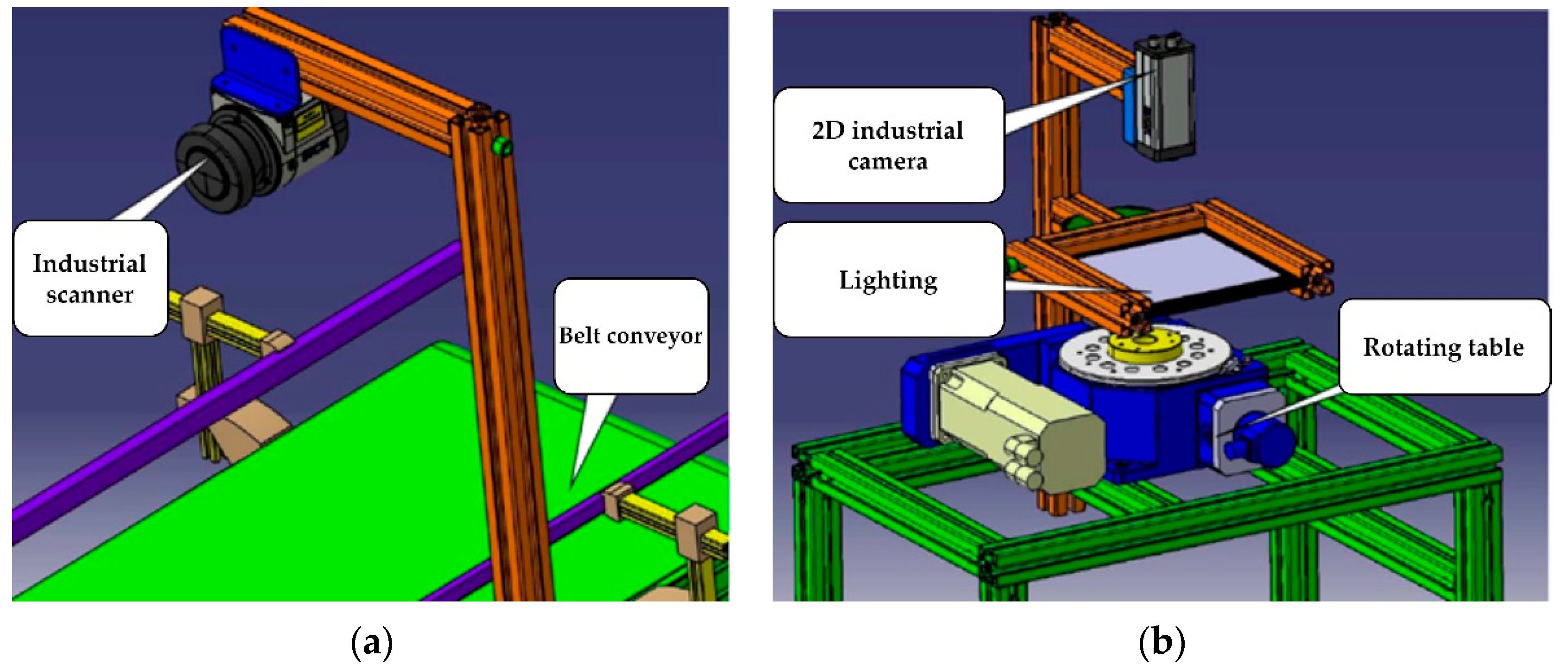
Module with translational movement and 2D measurement—intended for checking elements in 2D view (
Figure 4a).
Module with translational movement and 3D measurement—intended for checking the third dimension of parts (
Figure 4b).
Module with translational movement and profilometer—represents a combination of a precise identification device intended for measuring profiles and a translational positioning device known as a belt conveyor (
Figure 5a).
Color control module—contains a special sensor capable of identifying different types of colors from the color spectrum.
Module with translational movement and 2D comparison—with the help of this module, you can check things such as the simple presence of structural elements in the part.
Module with rotary motion and 2D measurement—uses the same identification device as the module with translational motion, i.e., 2D industrial camera with a higher level of evaluation (
Figure 5b).
A module with rotary movement and 3D measurement—the positioning part is thus provided with a freely positionable rotary table, which can be used to ensure the smooth rotation of the part within the field of view of the 3D camera.
Module with rotary movement and profilometer—the conceptual design of the used components can be based on previously used modules. The advantage of using a profilometer module over a module with a 3D camera is again seen in terms of the measurement geometry in certain special cases.
Module with rotary movement and 2D comparison—use is oriented towards the identification of simpler structural elements.
Module with digital scale—this module is designed to determine the weight of the inspected part.
Module for measuring the depth of narrow holes—an accurate laser triangulation sensor, which has an appropriate measurement geometry and can measure this depth parameter, is utilized in the module for measuring the depth of small holes.
Integrating handling modules—the task of these modules is to ensure the handling of parts between individual control modules.
An important feature of NC machine tools is achievable and repeatable machining accuracy. In practice, accuracy is determined by the characteristics of the NC machine and the chosen technology.
3.3. IMCS Database System Proposal
It is essential to adjust each component of the system, because one of the fundamental concepts in its design is openness and flexibility. The database structure holds information about the tolerance bands, component types, designations, and dimensions of each axis of the coordinate system. The modularity of the entire system—comprising separate data blocks that can be merged in different ways—is evident in the way the database is designed. Three types of databases are used by this intelligent system:
The component database, which keeps comprehensive records of every element and its specifications.
The module database, which houses details on every identification and handling module that is accessible.
The measured data database, which contains the measured data. It includes measurement data, which the system verifies based on the necessary values.
3.4. Design of Management of IMCS and Its Elements
The Potential of Distributed Control in Modular Systems—Modular systems leverage decentralized or distributed management principles, wherein the entire system is partitioned into distinct submodules, each equipped with its own control systems. Intercommunication among these modules is established, with each module dutifully executing its predefined role.
Utilization of Personal Computers (PCs) in Control Systems—The utilization of personal computers (PCs) within industrial contexts entails unique considerations, distinct from those relevant to other forms of control systems. Within the framework of a decentralized module management system, PCs typically occupy a distinct tier within the overarching hierarchy, assuming the role of a supervisory entity or a dedicated platform for data acquisition, storage, and analysis.
Integration of Microcomputers into Industrial Control—Microcomputers are prevalent in industrial settings, but they are not primarily employed as control systems tasked with overseeing entire pilot stations.
Adaptation of Robot Control Units in Control Systems—Robot control units are designed exclusively for the management of robotic entities. While they can serve as control systems for entire pilot stations featuring robots, their integration necessitates collaboration with other control systems, such as programmable logic controllers (PLCs).
3.5. Conceptual Design of a Spatial Solution for the Modules
In designing a spatial solution for the intelligent modular control system (IMCS) (
Figure 6a), it is necessary to proceed from the possibility of arranging individual modules freely. According to the purpose of use, we propose the division of the modules into the following categories (
Figure 6b):
Fixed Modules—Constituting integral elements of the integrated modular control system (IMCS), fixed modules serve as mandatory components within the control process, necessitating their identification at a minimum of one module per part. Fundamental data regarding the component type are promptly relayed to the control system for analysis via the information system. Concerning the technical integrity of fixed modules, a recommended solution comprises the fusion of belt conveyors alongside the use of industrial-grade 2D and 3D cameras. Parameters encompassing movement dynamics, resolution accuracy, and other pertinent factors must be meticulously selected based on the controlled spectrum of components.
Variable Modules—These modules are dynamically incorporated into the fixed modules upon prompting from the control system. Their primary function is to discern additional parameters that may not have been captured by the fixed modules. Their integration is facilitated through modular components, the configuration of which can be adjusted as needed, as is exemplified by industrial robots or manipulators.
This arrangement was chosen because the cellular structures ensured interconnection between the machines and saved time and space. In this method, the activity of the means of production was synchronized, and the material flow was fast. Such an arrangement makes it possible to adapt the behavior of IMCS to the control requirements, and it can be configured quickly.
4. Application of the Methodology in Real Conditions
The main goal was to produce a prototype of an intelligent modular system for use in the quality control of manufactured parts, with applications involving real components of real size. Creating a working prototype of an intelligent modular system for manufactured-part quality control using actual parts and real sizes was the primary objective of the practical verification. The system’s individual software and hardware components (modules) were described in the preceding chapter. As per the second chapter, the modules were classified into several groups (
Figure 7).
System modularity, flexibility, reconfigurability, and adaptability were given top priority in the design of the control system for the InMoSysQC component quality control facility. Its purpose is to measure the measured sample’s parameters to regulate their quality. The design of an appropriate, flexible control system that can measure and manipulate such samples is strongly tied to this broad range of measured samples.
4.1. PLC Controllers and Their Module Cards
The modular PLC (programmable logic controller) machines of the Mitsubishi Qx type serve as the fundamental integration units of the overall system. A card with a basic control unit (CPU) and other necessary types of expansion module cards are installed in every modular PLC machine. Among these expansion cards are the following:
The basic control unit CPU—This is designed to perform all basic control calculations and control functions. It is used to perform control algorithms, undertake parameterization, and determine the configuration of the entire device. It is an essential element in the maintenance of the autonomy of the PLC automaton.
Communication card CP for IE—The purpose of the communication card CP for IE is to use the TCP/IP communication protocol to link the PLC automaton to the IE network. This card allows the PLC automaton in the InMoSys QC device to communicate with other control modules. It is found on each automaton. The Internet Explorer network represents an open channel for signal transmission between individual modules and their submodules. An IP (internet protocol) address, the network designation (net_no), and the module designation (st_no), or station, are used to identify each module connected to the industrial Ethernet [
22].
Card with DI digital inputs—The purpose of a card with DI digital inputs is to connect optical components, induction components, and other sensors, buttons, and control components that output binary information to communication networks but lack an embedded communication processor.
Card featuring digital outputs (DO)—Its purpose is to connect actuators (pneumatic, electric, etc.) and display signals, as well as other devices that respond to binary input signals but lack an integrated communication processor that would allow them to be connected to communication networks.
Card for the MES operational production system—This serves to enable direct connection to higher levels of distributed control systems using the TCP/IP protocol via the IE network. With the help of SQL queries, this PLC card enables the automaton to save and select the required data from information database systems.
Positioning card PM—This intended to enable the control, positioning, and interpolation of servomotors. One card can control multiple axes depending on the type of card used.
Communication card for CC-Link—The purpose of the CC-Link communication card is to connect to peripheral devices using the CC-Link communication bus. Multiple devices that can communicate via a serial communication bus, such as CC-Link, can be linked to it.
Communication card for RS-232—The purpose of an RS-232 communication card is to connect to peripheral devices using the RS-232 communication bus. The serial communication bus called RS-232 only permits two-point connections. There are two communication ports on the card.
Communication between PLCs using Ethernet—Ethernet is used for communication between PLCs in IMCS. Every PLC has an Ethernet module that may be used for emailing; FTP server functions; PLC-to-PLC, PLC-to-PC, and PLC-to-camera connections; and other things. Open connections and connections meant for the system are the two main categories into which connections can be separated [
23,
24,
25,
26,
27].
Communication between PC and PLC—As mentioned, every IMCS PLC contains an Ethernet module, which is also used for communication between PC and PLC. For this method of exchanging information, we used two types—communication using GX Works and communication using the MC protocol.
Communication via GX Works—With the help of communication via Ethernet with GX Works, we monitored the program while it was running and could monitor its behavior or simulate certain states. We set up access to the Ethernet via GX Works in the Connection Destination program, where we could edit connections or create new ones. After selecting the connection, we set “PC side I/F” to “Ethernet Board” and specified the PC network number and PC station number, and then we set the Ethernet module.
Communication using the MC protocol—When communicating using the MC protocol, the connection can be opened or used for the system. We used an open connection for IMCS.
4.2. Characteristics of the Selected Control Object
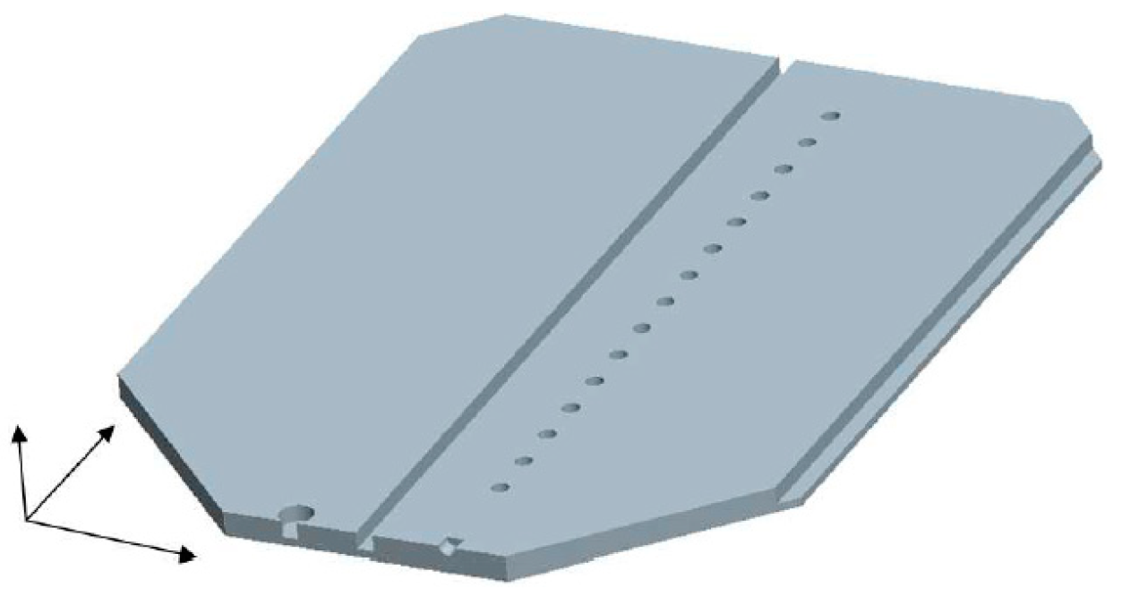
The company operates in the furniture industry, producing chipboard parts. The aim of this case study was, first, to speed up the adjustment control process when cutting and drilling tool heads directly in the production hall. The external dimensions of the produced parts, the exact position and depth of the structural elements on the parts, the perpendicularity of the edges, and the dimensions of the profile groove had to be checked. It was a matter of course that the complete archiving of the achieved data was performed. All these conditions had to be met by the facility, as well as the financial return of the entire investment, within a certain time. Different types of holes (continuous, non-continuous), grooves, half-grooves, and recesses were produced on the parts. The holes were located on several sides of the parts and had different ratios of depth to diameter. The measurement procedure is predicated on information from specified wooden part templates that are kept in the database. A universal template for a wooden element is shown in
Figure 8. Templates for actual wooden pieces are made using this universal template. Every wooden part template has components like a hole and a corner point. A groove entity can also be formed by a collection of points.
The industrial PC communicates with the camera through the OPC server regarding the type of measured item and its color. Using a positioning device and information from the database, the industrial PC places the camera beneath the anticipated object. A corresponding subprogram is launched based on the type of entity measured once the camera has been positioned at a predetermined location beneath it. After that, an image of the entity is captured with exposure, matching the color of the measured portion. The image is then segmented using thresholding, detection, entity identification, and the measurement procedure itself. The deviations of the object from its predicted position and dimensions are sent to the PC following the subprogram’s execution. The camera system measurement procedure is broken down into multiple subprograms, which is dependent on the type of measured entity. These subprograms are started using data from the industrial PC’s control system.
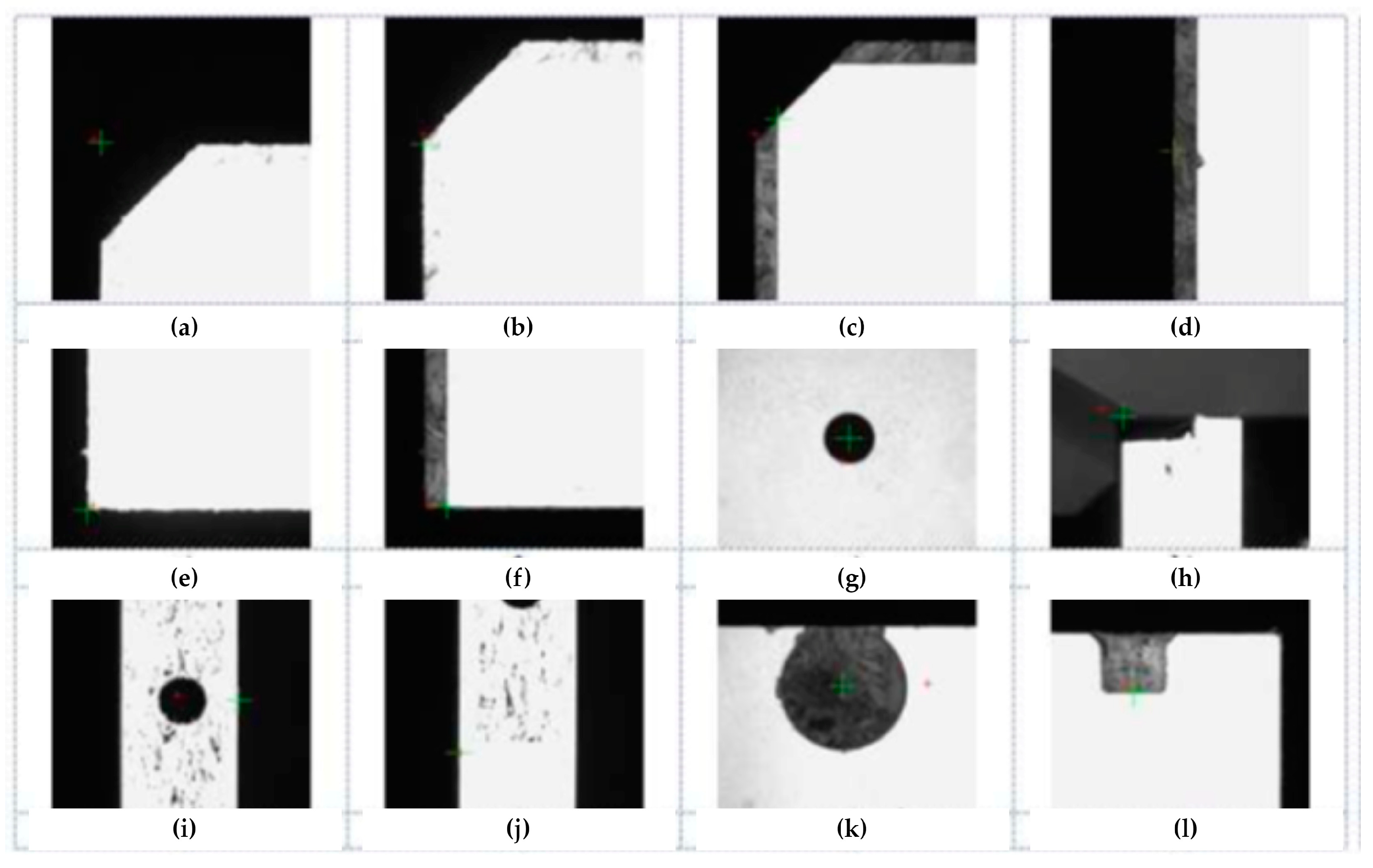
Figure 9 contains the fundamental scanned entities. Examples of chosen measurement objects include portions from actual photographs that have the estimated position indicated as a large target for visual examination and the field of view center indicated as a tiny target.
The most complicated case is the calculation of the position and diameter of the incomplete hole on the edge of the part (
Figure 9k). In this case, the position and diameter of the hole are obtained using a search engine that works on the principle of object similarity searching. When programming the camera, it was necessary to teach the search engine all the necessary objects, defining their position and dimensions. The best solution turned out to be the creation of perfect reference objects, for which the exact position and dimensions were calculated.
4.3. The Sequence of Implementation and Presentation of Results
The device was assembled and tested in experimental conditions. The team of workers focused on construction started with the assembly work, and the programmers worked simultaneously with them on the development of the software part of the system. We verified the accuracy of the assembly using the FARO 3D measuring arm (
Figure 10a). During the test operation, we adjusted the correction parameters based on the results of the measurement using a laser interferometer, and we measured the accuracy as the repeatable positioning accuracy of all positioning mechanisms (
Figure 10b).
After the approval of the number of control measurements, the device had to be disassembled. After the device was transported, assembly was carried out again on the premises of the production hall.
5. Results
The application of the methodology in practical conditions was divided into three phases: the preparatory phase, the implementation phase, and the output phase.
Preparatory phase—The parts were classified into the group of surface parts based on their shape. The next step was integrating the model data into the component database. The information it stored included part dimensions, the location and depth of individual holes and grooves, details about the side that a given parameter was located on, the “zero point” to which all data were compared, the part name, the tolerance field for the specified parameter, and an identification number for each parameter (
Figure 11).
The term “zero point” was developed to unify measurements because, up until this point, manufacturers measured items without using any standards.
Figure 12 displays the device database’s structure.
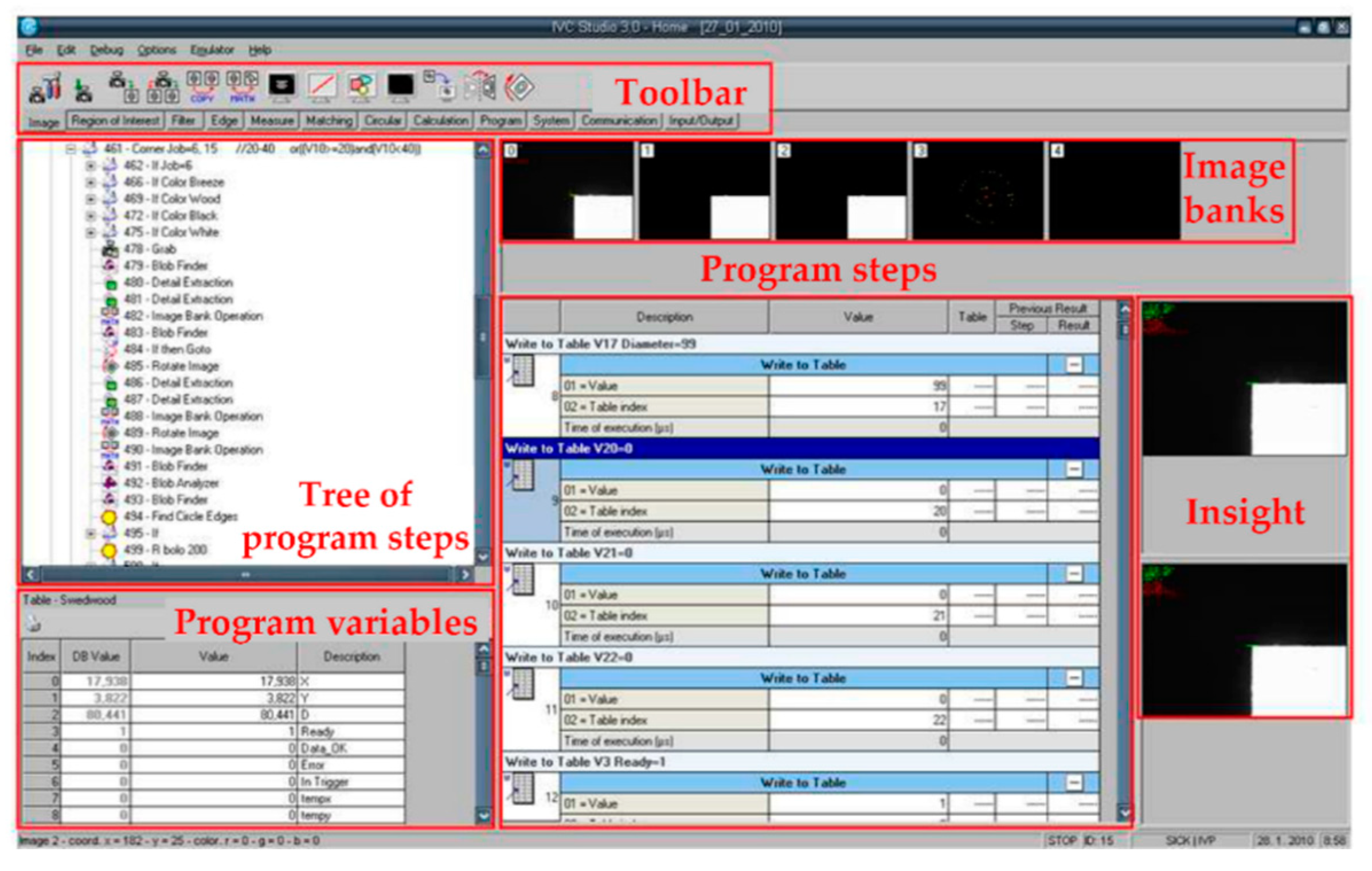
During the parameterization of the setup, all the evaluation sequences of the program were determined for a specific evaluation module.
Figure 13 shows how to set the correct exposure and recognition algorithms.
Implementation phase—Every aspect of the component, including its length, width, thickness (X, Y, and Z), the diameter of the hole, the coordinates of the chosen element’s position (x, y, and z), and the depth of the hole, was chosen for examination. Because parts can be made in multiple color variations, the operator chooses the color of the component to be measured and decides on the measurement technique in further detail. This information constitutes the data needed independently for a given measurement. The operator also needs to choose additional required options (
Figure 14).
The program chose a precise 2D measuring system to determine the size and locations of the holes from the relational matrix based on the parameters that were chosen to be measured. The depth of the holes and grooves that were created was measured using a triangulation laser sensor, which is the only method with a measurement design that guarantees the complete identification of the specified parameter. The use of another algorithm for figuring out when to activate the modules showed that you must figure out where the holes are made and then use a laser sensor to figure out how deep the hole is.
Output phase—After the measurement is finished, the measured data are exported to the database and compared with the model data. The operator can display the measured deviations on the monitor or print them out. The measured data are copied once a day to the main server of the production company, where the user can monitor individual deviations during a certain time interval, check the parameters independently, and, based on this, determine corrective solutions such as the replacement of a drilling head that exhibits frequent drilling errors.
During the installation of the device for the customer, a problem arose with repeatability and accuracy measurements. These problems were caused by the fact that the measurements of the same parts did not take place during constant temperature conditions (the temperature range varies from 18 °C to 37 °C during the year). The solution was the installation of temperature sensors and the production of a calibration part.
The calibration part served as a standard and was made of aluminum alloy with dimensions of 2300 × 900 × 8 mm.
After the production of the standard, the certified company carried out measurements at different temperatures in the interval from 15 °C to 28 °C. These measurements served as a basis for determining the thermal expansion of the material used because the manufacturer could not provide us with the exact data. It is necessary to calculate the thermal expansion coefficient ∝ from the following relationship:
Only table data were provided, which did not fully correspond to reality ∝ = 15.7 m/m.K.10
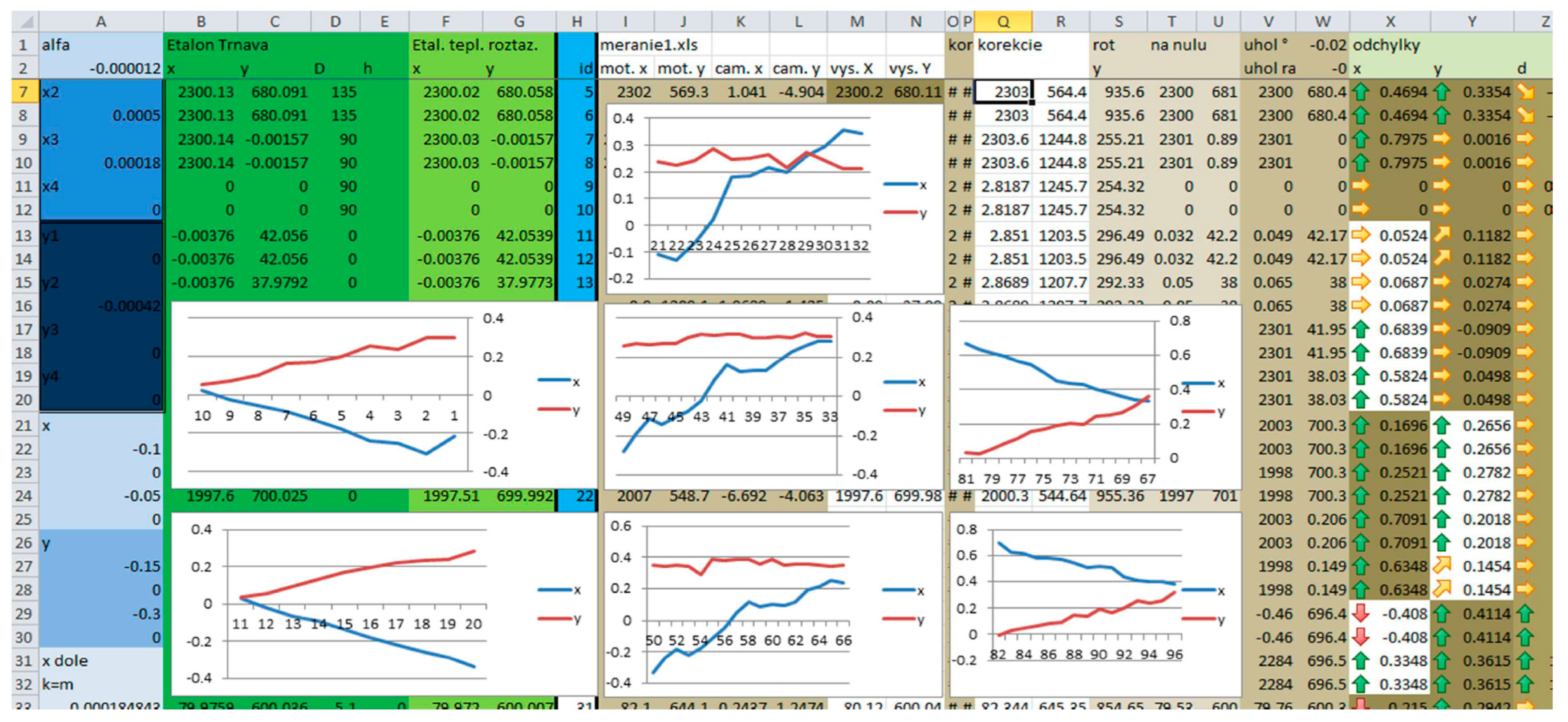
−6. During the calibration measurements, the database values (measured by a certified company) and the actual values supplemented with the coefficient of thermal expansion (measured by the measuring device) were compared. Based on the outputs from the measurement of the standard, we could automatically correct all measured values at various temperature changes. Samples of value curves in the individual axes, before and after setting the temperature change corrections, can be seen in
Figure 15 and
Figure 16. The figures show the deviations in the values in the individual axes for the corresponding measured holes. The x-axis is the number of the measured holes, and the y-axis shows deviation in millimeters from the actual value.
The figures (
Figure 15 and
Figure 16) show the deviations of values in individual axes for the corresponding measured holes. The x-axis is the number of the measured hole, and the y-axis shows the deviation in millimeters from the actual value.
The deviations achieved for individual axes are displayed in
Figure 17. The graph displays the repeatability of the automated device’s measurement, as well as the accuracy of the chipboard part production. The use of the gadget resulted in an average of 40–60% time savings over the prior manual control method. Entire measurement data archiving was guaranteed, and finally, human error— which contributed significantly to this process’s error rate—was eradicated.
6. Discussion
In practice, we come across approaches and devices that, thanks to the use of the most modern technologies, can meet the requirements set for the identification of various parameters to the desired extent. The problem, however, is that they are mostly either single-purpose devices, whose processing speed is fast, but they can identify only one parameter or a narrow band of controlled parameters. Another disadvantage is that it is sometimes necessary to bring about a time- and materially expensive change in the spatial arrangement of the workplace. On the other hand, they are highly accurate multi-purpose devices, where the needs for accuracy are met to the maximum extent. However, the duration of the inspection itself does not give the possibility of checking every manufactured part. In such instances, there is room for deploying intelligent modular control devices such as those mentioned in this study.
A series of tasks that must be completed before the initiation of the control process defines the preparatory phase. These mostly involve the categorization and classification of components, as well as the entry of data into distinct databases. The parameterization of settings is a crucial step in the preparation phase:
Part coding, grouping parts into component bases, and component classification [
28,
29].
Adding parametric data for specific modules and dimensional data for components to other control system databases (such as CAD data) [
30].
Establishing potential measuring parameters [
31].
Configuring the parameterization [
32].
There are three primary stages to the IMCS activity technique (
Figure 18).
Implementation phase—The implementation phase is characterized by the control process used on the devices themselves. The process includes a moment when the operator directly selects individual parameters to be checked in the control menu. In this phase, the selection and activation of modules suitable for checking the required parameters using individual components is also carried out automatically.
Output phase—After the end of the measurement process, the superior control system exports the measured data to the database of the measured data. By simply subtracting the drawing data stored in the component database from the data stored in the measured data database, a deviation from the required dimension will occur. For each parameter, its respective limit deviation is determined based on production drawings. If the difference between the measured value and the drawing value is higher than the permitted limit deviation, this parameter is declared faulty.
Four fundamental classes of checked parts were selected for the practical verification solution: flat parts, cabinet parts or 3D plastic-injection moldings and moldings, rotary parts, and shaft parts. A photo of a particular part, a camera image, or its three-dimensional model are examples of auxiliary data that provide a better visual representation of the categorized parts.
Based on the shape difference, it is possible (most often experimentally) to define the relationship between the measured parameters depending on the technical devices used.
The initialization of variables is performed at the beginning of the process. In the initial phase, the part (
Sm) is identified using the input identification module. In the next block, data for a specific part are loaded from the component database shown in mathematical Equation (4). Subsequently, a check occurs, which determines whether the specific parameter represented in the mathematical Equation (5) is selected from the entire set of parameters. The number of selected parameters (the number of elements of the set of selected parameters) is written as the variable “k”. If this parameter is not selected, the next parameter is checked automatically. If the algorithm identifies the selected parameter, the module suitable for its control is determined. It is then necessary to use the relational matrix of parameters and modules, as well as the database of modules, as input data. This is used to check one parameter. This process (
Figure 19) is repeated until all parameters selected by the operator (x = k) are checked. Subsequently, individual modules are activated.
7. Conclusions
The article provides an innovative approach to solving the problem of control operations prior to a component’s introduction into assembly. The methodology proposed in this work consists of connecting several types of functional blocks in each of the phases mentioned in
Section 3.4. Two decision-making algorithms were used in the work. One was an algorithm for selecting suitable types of control modules and the other was an algorithm for the gradual activation of individual modules. The methodology was applied in the design of the automated measuring device AMZ_01 while using a significant part of its system elements. Based on results from the studied literature, we advanced theoretical and practical knowledge, and designed and verified a solution. For further research in this area, it is recommended to focus individually on all phases of the system. Additional recommendations for further research include the following examples:
Detailed design of the structure of database systems in terms of the modularity of devices and the complexity of the entire system.
Another method of selecting modules that are suitable for parameter control—the use of expert systems appears to be the most advantageous method in this area.
The creation of a complex software package for the design and management of control systems [
33,
34,
35].
Equipment in the pre-assembly stage [
36,
37,
38,
39].
Development and application of colonic systems [
39,
40,
41].
The design of control devices during the pre-assembly phase presents a promising avenue for enhancing product quality and mitigating the costs associated with detecting deficiencies in the assembly process. The proposed system entails the utilization of distinct functional modules that are capable of overseeing one or multiple measurement/control parameters. Users are afforded a breadth of options in order to tailor and oversee this process, including adjustments to workplace layouts and the selection of specific controlled parameters [
42,
43].
The theoretical segment delineates elements of the system that are pertinent to our research, encompassing an analysis of the current research landscape with regard to flexible, cost-effective control-device domains. It elucidates how production process design paradigms intersect with advancements in information and communication technologies. However, existing systems are largely tethered to either human collaboration or the labor-intensive configuration of control processes and measurements. Their practical applications involve approaches and devices that leverage state-of-the-art technologies to fulfill diverse parameter identification requisites.
Nonetheless, prevailing devices are predominantly single-purpose, high-speed units capable of discerning limited parameters or highly precise multi-purpose devices unable to scrutinize every manufactured part within feasible time frames [
44,
45]. This creates an opportunity for the deployment of intelligent modular control devices, as discussed herein [
46,
47].
The crux of this research delineates components of the integrated modular control system (IMCS), including classification and database systems, as well as control algorithms. This section expounds upon the methodology of flexible IMCS, and potential variants of control modules predicated on cost-effective automation. Integral to IMCS is the establishment of a comprehensive relational matrix connecting controlled parameters with control modules. Decision algorithms [
48,
49], governing the selection and sequential activation of control modules, ensure system functionality. The proposed solution obviates the necessity for specialized experts to continuously design new control systems in response to production changes. Rather, it enables experts to be engaged solely during the initial system implementation phase, with subsequent operations being overseen by operators.
The possible benefits of this study for the development of practice include the following perks:
Simplification of the design process of control workplaces;
The possibility of using a wide range of controlled parts;
A simpler control system without the presence of human operators;
The proposed solution offers a universal solution that is not restricted to use in the pre-assembly stage,
Aetting up direct feedback on the production process.
Based on the insights gathered from the reviewed literature, theoretical research, and practical findings, as well as the proposed and validated solution in the article, it is recommended that future research in this area should focus individually on all phases of the system. Specifically, there is a need for a detailed design of the database system structure, considering the modularity of the device and the complexity of the entire system [
50,
51]. Additionally, further exploration of methods for the section of modules that are suitable for parameter control, with the use of expert systems appearing to be the most advantageous approach in this area, is warranted. Moreover, the development of a comprehensive software package for designing and managing control devices in the pre-assembly stage would greatly enhance system efficiency. Lastly, the elaboration and application of holonic systems presents promising avenues for future investigation.
In conclusion, while this study has provided valuable insights and solutions, it is important to acknowledge its limitations and potential areas for improvement. The drawbacks of the study, such as limitations in scope or methodology, should be discussed transparently. Furthermore, highlighting potential future work can guide researchers in further advancing the field and addressing unresolved challenges. By addressing these aspects, future research endeavors can contribute to the continuous evolution and enhancement of intelligent production systems.


 ,
, 


