Article

Enhancing Fault Ride-Through and Power Quality in Wind Energy Systems Using Dynamic Voltage Restorer and Battery Energy Storage System

by
Ahmed Muthanna Nori
1,
Ali Kadhim Abdulabbs
1,
Abdullrahman A. Al-Shammaa
2,* and
Hassan M. Hussein Farh
2
1
Electrical Engineering Department, College of Engineering, University of Basrah, Basrah 61001, Iraq
2
Electrical Engineering Department, College of Engineering, Imam Mohammad Ibn Saud Islamic University (IMSIU), Riyadh 11564, Saudi Arabia
*
Author to whom correspondence should be addressed.
Electronics 2025, 14(14), 2760; https://doi.org/10.3390/electronics14142760
Submission received: 21 May 2025 / Revised: 1 July 2025 / Accepted: 3 July 2025 / Published: 9 July 2025

Abstract

Doubly Fed Induction Generator (DFIG)-based Wind Energy Systems (WESs) have become increasingly prominent in the global energy sector, owing to their superior efficiency and operational flexibility. Nevertheless, DFIGs are notably vulnerable to fluctuations in the grid, which can result in power quality issues—including voltage swells, sags, harmonic distortion, and flicker—while also posing difficulties in complying with Fault Ride-Through (FRT) standards established by grid regulations. To address the previously mentioned challenges, this paper develops an integrated approach utilizing a Dynamic Voltage Restorer (DVR) in conjunction with a Lithium-ion storage system. The DVR is coupled in series with the WES terminal, while the storage system is coupled in parallel with the DC link of the DFIG through a DC/DC converter, enabling rapid voltage compensation and bidirectional energy exchange. Simulation results for a 2 MW WES employing DFIG modeled in MATLAB/Simulink demonstrate the efficacy of the proposed system. The approach maintains terminal voltage stability, reduces Total Harmonic Distortion (THD) to below 0.73% during voltage sags and below 0.42% during swells, and limits DC-link voltage oscillations within permissible limits. The system also successfully mitigates voltage flicker (THD reduced to 0.41%) and harmonics (THD reduced to 0.4%), ensuring compliance with IEEE Standard 519. These results highlight the proposed system’s ability to enhance both PQ and FRT capabilities, ensuring uninterrupted wind power generation under various grid disturbances.

1. Introduction

The global energy landscape has been significantly influenced by the rapid lessening of fossil fuels and their rising costs, driving an urgent shift towards renewable resources. Therefore, renewable energy serves as an alternative way of overcoming the anticipated power crisis [1]. Among various renewable options, Wind Energy Systems (WESs) have emerged as one of the most promising and rapidly growing alternatives, owing to their abundance, environmental benefits, and cost-effectiveness. The contribution of WESs to global electricity generation is expanding at an unprecedented rate, making them a cornerstone in achieving energy sustainability [2]. However, the inherent intermittency and variability of WESs pose major challenges to the power quality (PQ) and the reliability of power delivered to the grid [3]. PQ issues associated with WESs are particularly critical. These issues include voltage sags, swells, flickers, harmonics, and unbalanced conditions, which can disrupt grid stability and impact sensitive equipment. These disturbances can lead to equipment damage, reduced lifespan, and operational inefficiencies [4]. So, PQ issues have recently become the central focus of interest for several researchers.
During grid fault conditions, the isolation of a WES disrupts the equilibrium between power generation and grid demand, resulting in significant supply–demand imbalances within the electrical network. To ensure the system’s stability and reliability, new grid codes have been established in response to the growing wind energy capacity and the connection of large single WESs to the grid. The grid codes dictate that the WES must remain connected to the electric power systems during voltage fluctuations and be supported by providing reactive power to rapidly recover grid voltage [5]. Voltage sags/swells are the most common PQ issues, and they are usually related to system malfunctions. These faults include single-phase-to-ground faults (SPG), two-phase-to-ground faults (2PG), and three-phase-to-ground faults (3PG). A swell may arise from a temporary voltage increase on the unfaulted phases during an SLG fault. Additionally, swells can result from disconnecting a large load or activating a large capacitor bank [6]. The High-Voltage Ride-Through (HVRT) capability mandates that WESs remain connected to the grid during over-voltage events, as required by grid codes. To comply with Low-Voltage Ride-Through (LVRT) standards, WESs must maintain grid connection for a defined period during voltage dips [7]. Voltage flickers are sudden fluctuations in frequency for short intervals caused by load switching and the incorporation of compensating devices. Consequently, the reactive power demand in the output terminal of the WES negatively impacts voltage stability. Longer-lasting voltage swells or flickers can introduce harmonics into the system, and voltage collapse may result if the voltage sag persists. Also, sags/swells or flickers generate current that influences the protection system and switchgears [8].
Due to their affordability, capability to work at variable speeds while keeping constant frequency, and advanced four-quadrant reactive power management, Doubly Fed Induction Generators (DFIGs) are universally implemented in WESs [9]. In comparison to other generators in the same class (like squirrel-cage induction generators), A DFIG exhibits superior performance during the HVRT and LVRT. Nevertheless, a DFIG is susceptible to external disturbances such as voltage swell and sag due to its direct connection to the grid. Sudden grid voltage drops cause large surge currents to flow into the generator terminals, damaging power converters and windings. Moreover, the rotor speed will increase, resulting in significant Electromagnetic Torque (EMT) pulsations that may shorten the lifespan of WES gearing. Due to the high incidence of these faults, many researchers have been inspired to mitigate the impacts of grid disturbances [10].
Several industrial controllers and protective devices have been developed recently to enhance the Fault Ride-Through (FRT) capability of DFIGs and mitigate power fluctuations. In [11], the authors proposed a protection scheme that involves the use of a Superconducting-based Fault Current Limiter (SFCL) to ensure that the DFIG remains stable under severe grid faults and varying wind conditions. A coordinated control approach is adopted for the DFIG to adjust power output—both reactive and active—during grid disturbances [12]. The crowbar circuit is recommended for DFIGs to enhance FRT ability during balanced or unbalanced disturbances [13]. An enhanced crowbar circuit, integrated with an ideal cascaded Fuzzy Logic Controller (FLC), allows the Grid-Side Converter (GSC) and Rotor-Side Converter (RSC) to manage transient fluctuations during severe faults [14]. To enhance the DFIG’s transient stability and FRT capacity, a non-superconducting Fault Current Limiter (FCL) of the diode-bridge type is suggested [15]. Superconducting Magnetic Energy Storage (SMES) and SFCL are coordinated to support the DFIG during fault conditions and improve its FRT compliance [16]. For the DC link of the conversion system, an SMES via a D-type chopper is designed to achieve the best positioning for reducing power instability [17]. In order to improve the system stability under various fault scenarios, the authors of [18] investigated the impact of incorporating SMES into DFIG in both grid-connected and standalone modes.
These control strategies effectively suppress rotor current surges and stabilize DC-link voltage, which leads to a significant reactive power attraction. Furthermore, they impose considerable mechanical stress on the gearbox and shaft [19]. While the passive components BC and SDR are cheap and straightforward, they are less efficient and lead to over-heating under severe running conditions [15]. Implementing independent power electronics-based compensation for voltage fluctuations can further enhance FRT capability. The STATCOM device was developed in [20] to augment LVRT and enhance the dynamic performance of grid-connected WESs. According to [21], optimum control of a novel PI λDμ-based Dynamic Voltage Restorer (DVR) can protect the DFIG from swell/sag voltage faults by injecting the required voltage at the WES phases. A synchronous reference frame control-based DVR can augment the FRT capabilities by injecting the required voltage at the WES phases, as demonstrated by [22]. The use of the SVC or STATCOM to enhance the FRT capabilities of a DFIG could not achieve high efficiency due to the low voltage at its terminals during grid fault conditions. A DVR can mitigate transients in the output voltages of the DFIG and rapidly restore voltage, thus improving the controllability of the back-to-back converter during disturbance to values equal to normal operation [23,24]. Furthermore, the cost and size of the DVR are lower than those of the STATCOM [25].
Aside from this issue, delivering a suitable voltage component during a voltage fluctuation requires a certain amount of active and reactive power. Traditionally, DVRs are made composed of an energy storage device that provides the power needed for the limited time of the fault. The large amplitude and lengthy duration of faults require significant financial investment in an energy storage unit. The authors of [26] employed a DVR to compensate for the voltage sags and swells. However, they replaced the DC-source of the DVR with the DC-link of a DFIG, lowering the investment cost and providing the necessary compensation energy for long-term voltage disturbances. Rather than using the DC-source and converter in a DVR, the authors employed the DFIG GSC and DC-link as a DVR [27]. Similarly, a GSC is combined with storage elements to form a DVR. During grid disturbances, the GSC and protection system are configured to activate the DVR’s compensation mode [28]. Although these innovations can lower investment costs, implementing these configurations in a wind farm is quite expensive as a DVR is required at each WES. Furthermore, employing additive power electronic switches for changing operating conditions may result in severe transients and an increase in cost. The authors of [29] combined a DVR and Battery Energy Storage System (BESS) with a DFIG to assess the system performance under fault operation conditions and time-varying wind speeds. To address grid voltage disturbances and enhance the PQ and FRT capabilities of WESs, the AC voltage generator proposed in [30] integrates a supercapacitor storage device into the DVR. In [31], the authors used the vector control strategy with PI controllers to manage rotor-side and grid-side converter parameters. During symmetrical faults, the authors employed a series grid-side converter (SGSC) with a shunt injection transformer to limit rotor current in compliance with grid code requirements. The authors of [31] analyzed DFIG fault characteristics and proposed using a DVR with an SMES to mitigate voltage dips and improve fault ride-through. Simulation results confirmed the method’s effectiveness in compensating fault stator voltage and maintaining fault current frequency at 50 Hz. In [32], the authors proposed a DVR system with an Asymmetric Cascaded E-type Bonded T-type Multilevel Inverter (ACEBTMI) and a Chattering Free Binomial Hyperbolic Sliding Mode Controller (CFBHSMC) to enhance the FRT capability of DFIG-based wind turbines. The simulation results confirmed the system’s effectiveness in compensating voltage fluctuations and enabling reliable operation during disturbances.
From the above literature review, it is clear that there is still a need for a comprehensive study on the dynamic response of DFIG-WT systems during different voltage disturbances, including swells, sags, voltage flicker, and voltage harmonics, as well as the role of the proposed protection scheme in improving the FRT and PQ of the DFIG connected to the grid. This study explores the use of a DVR and a BESS to enhance the PQ and FRT capabilities of a DFIG. The proposed setup builds on the conventional grid-connected DFIG topology by integrating a DVR and a BESS. During fault, the DVR quickly corrects asymmetrical and symmetrical sags, swells, flicker, and harmonics, maintaining the WES terminal voltage at its rated level for uninterrupted operation. The DVR is connected in series with the WES outputs and in parallel with the DC-side of the WES and BESS. The BESS control system monitors the DC-side voltage and adjusts the BESS’s stored energy based on voltage levels, working in tandem with the DVR to improve both FRT and PQ. This configuration will be particularly beneficial in wind farms, as one of the turbines will be responsible for voltage compensation. By utilizing the DC-link of the first wind turbine in the group along with a BESS, it ensures that voltage stability is maintained during external fault conditions, improving the overall reliability and performance of the wind farm. This centralized approach to voltage compensation helps reduce the need for additional, separate DVR systems for each turbine, thus offering both economic and operational advantages.
The core findings and contributions of this study are outlined below:
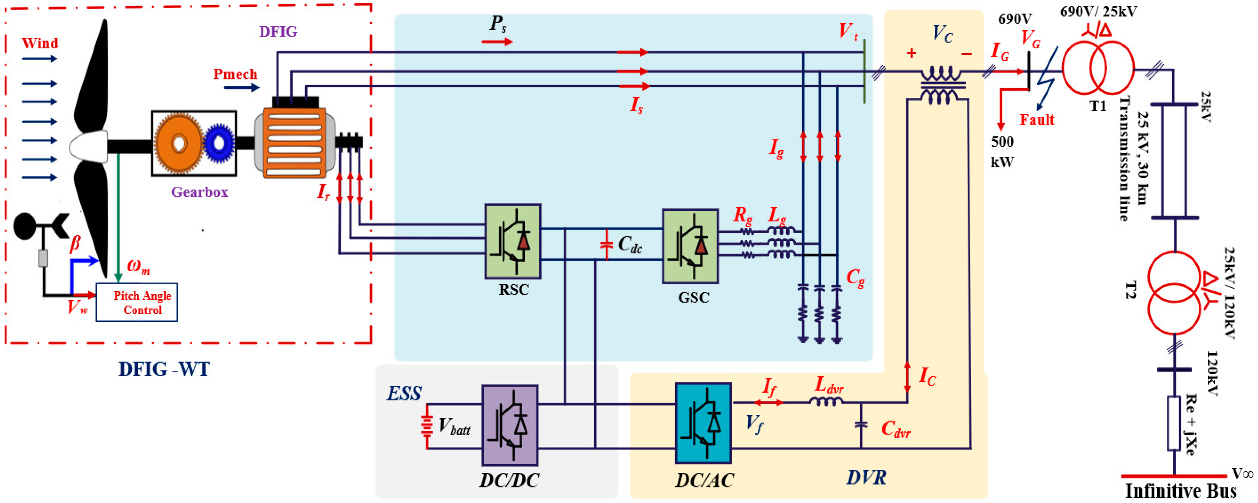
  • DVR-Based System Design: This study introduces an innovative DVR configuration, integrated at the WES terminal. It replaces the conventional DC source of the DVR with the DC link of a DFIG and a BESS. This ensures protection against grid disturbances and effectively mitigates system instabilities during grid faults.
  • Comprehensive Disturbance Evaluation: The proposed system is rigorously analyzed under various grid voltage disturbances, including voltage sags, swells, flickers, and harmonics, to validate its robustness and effectiveness.
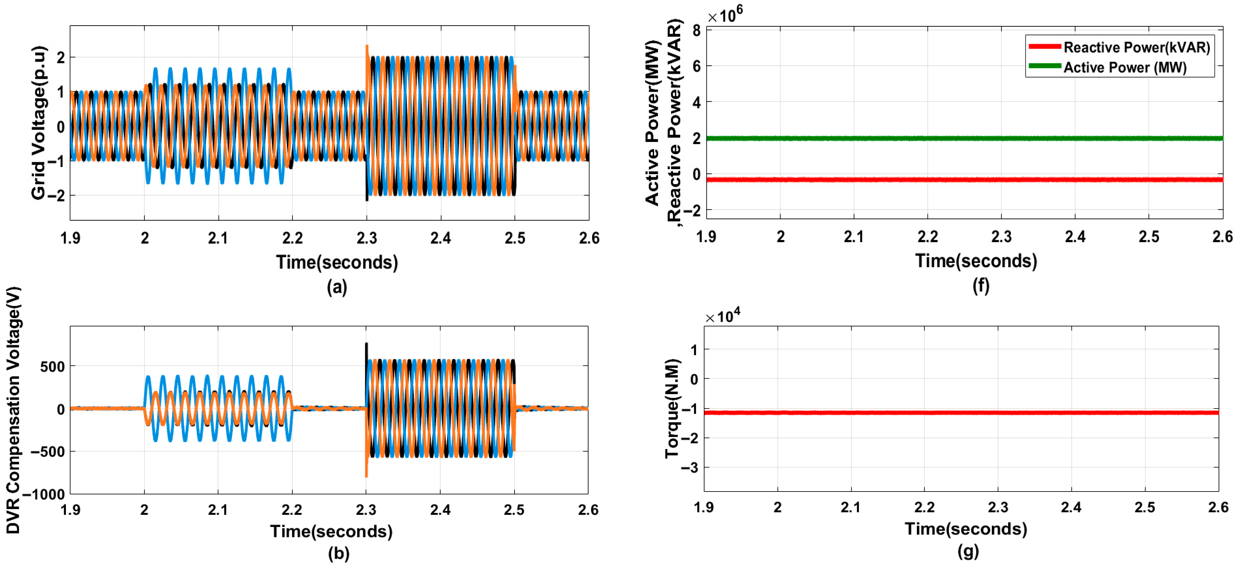
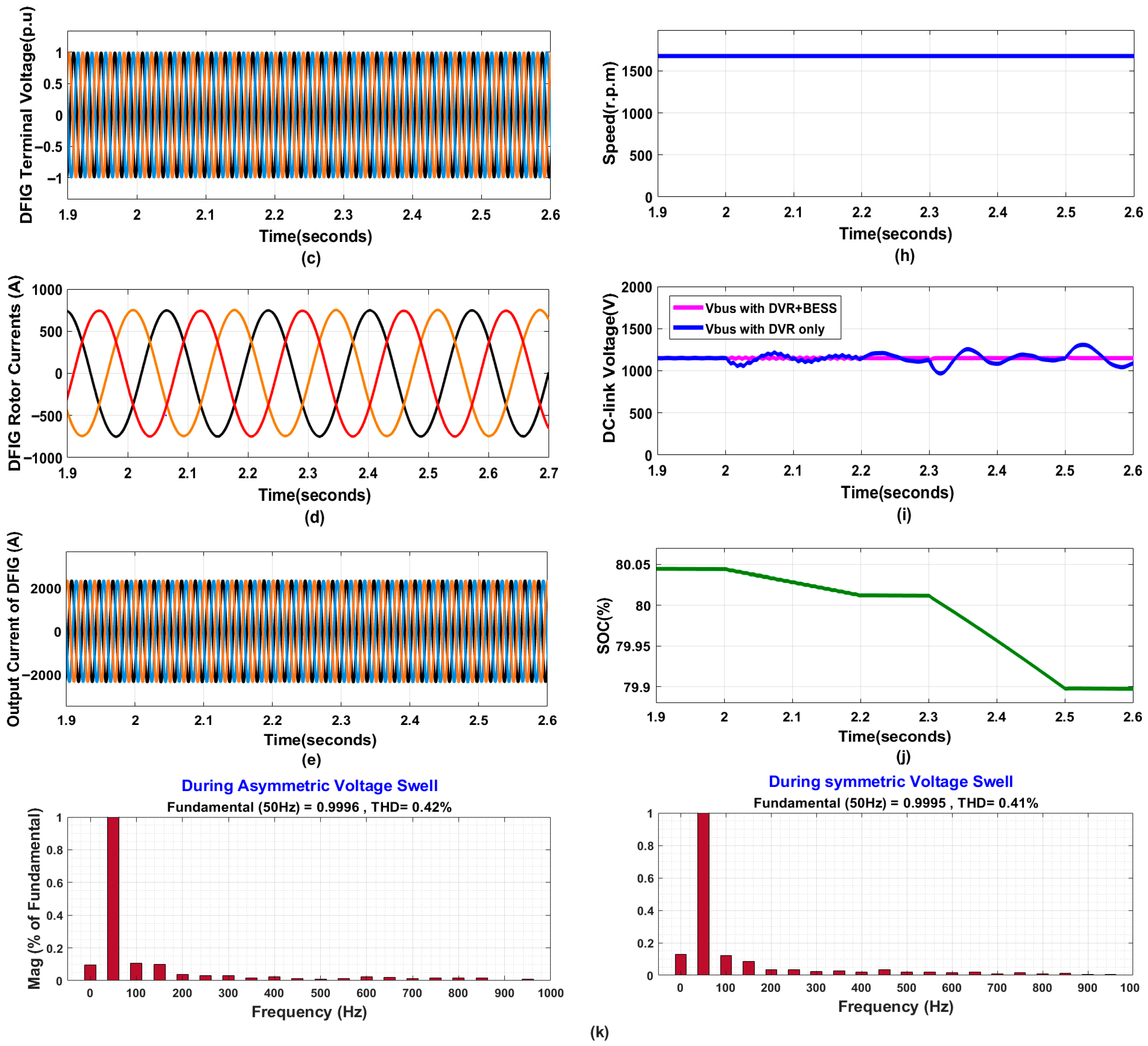
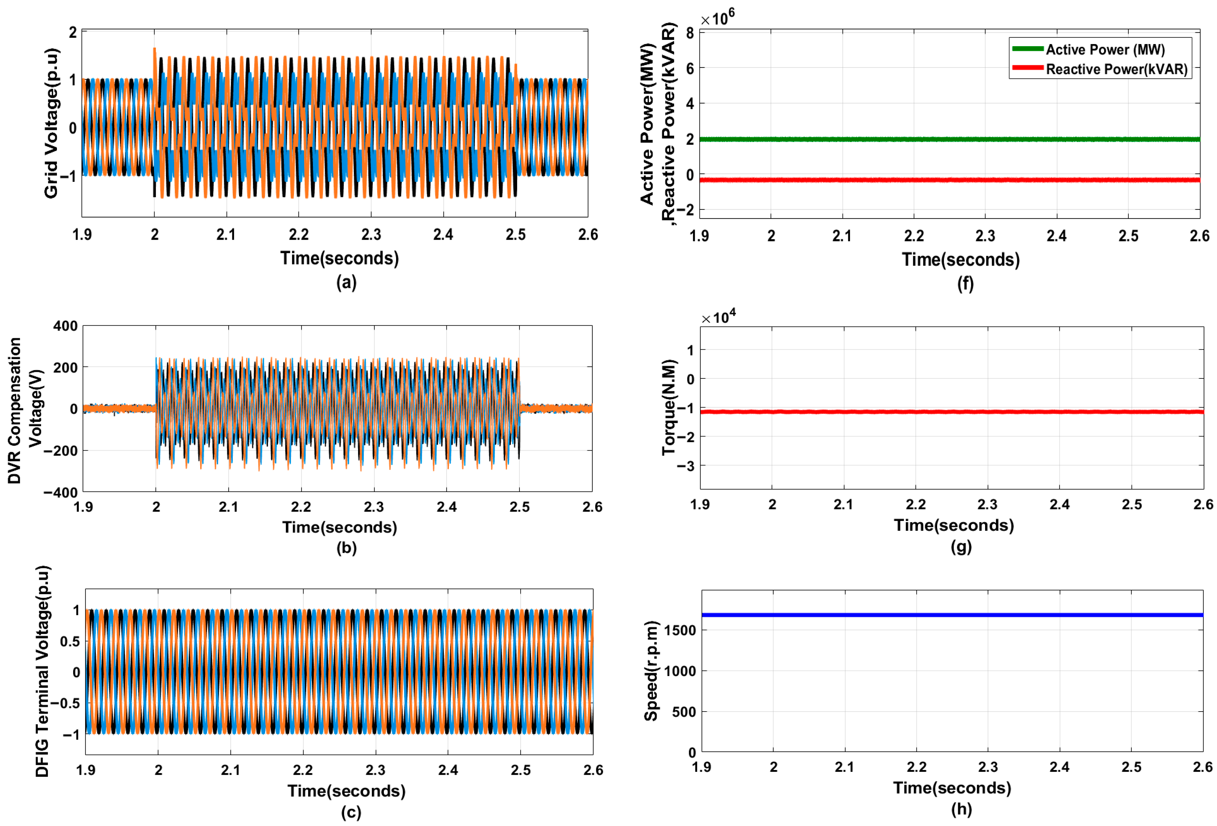
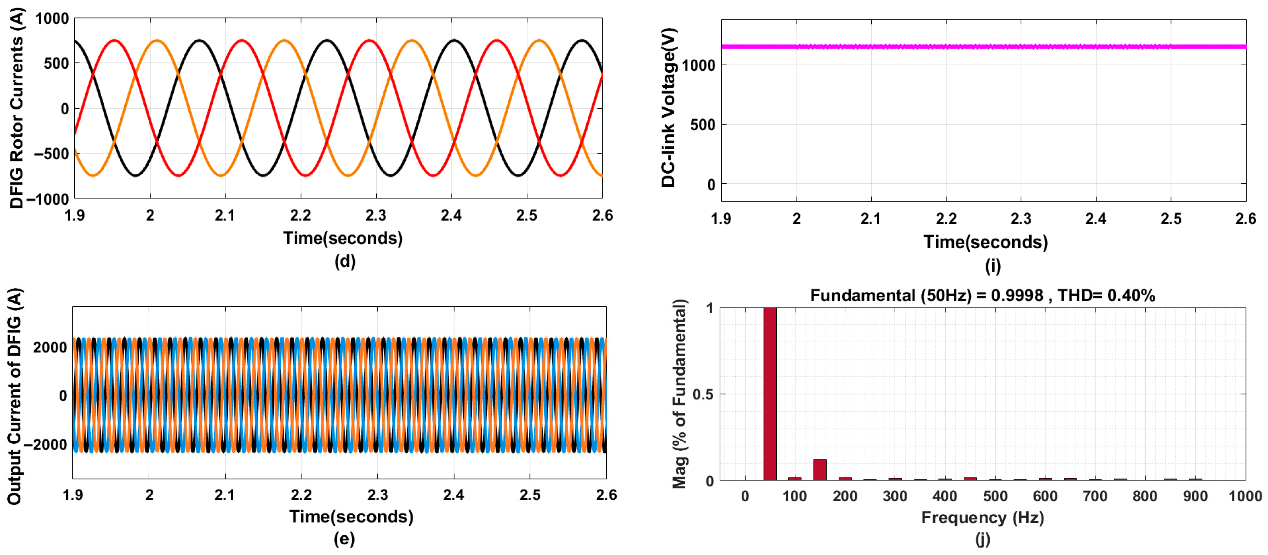
  • Enhanced Stability and FRT: The simulation results show that the proposed approach augments the stability and FRT capability of the DFIG-based WES by keeping key parameters, including rotor and output currents, active and reactive power, and DC voltage, within acceptable limits during faults.
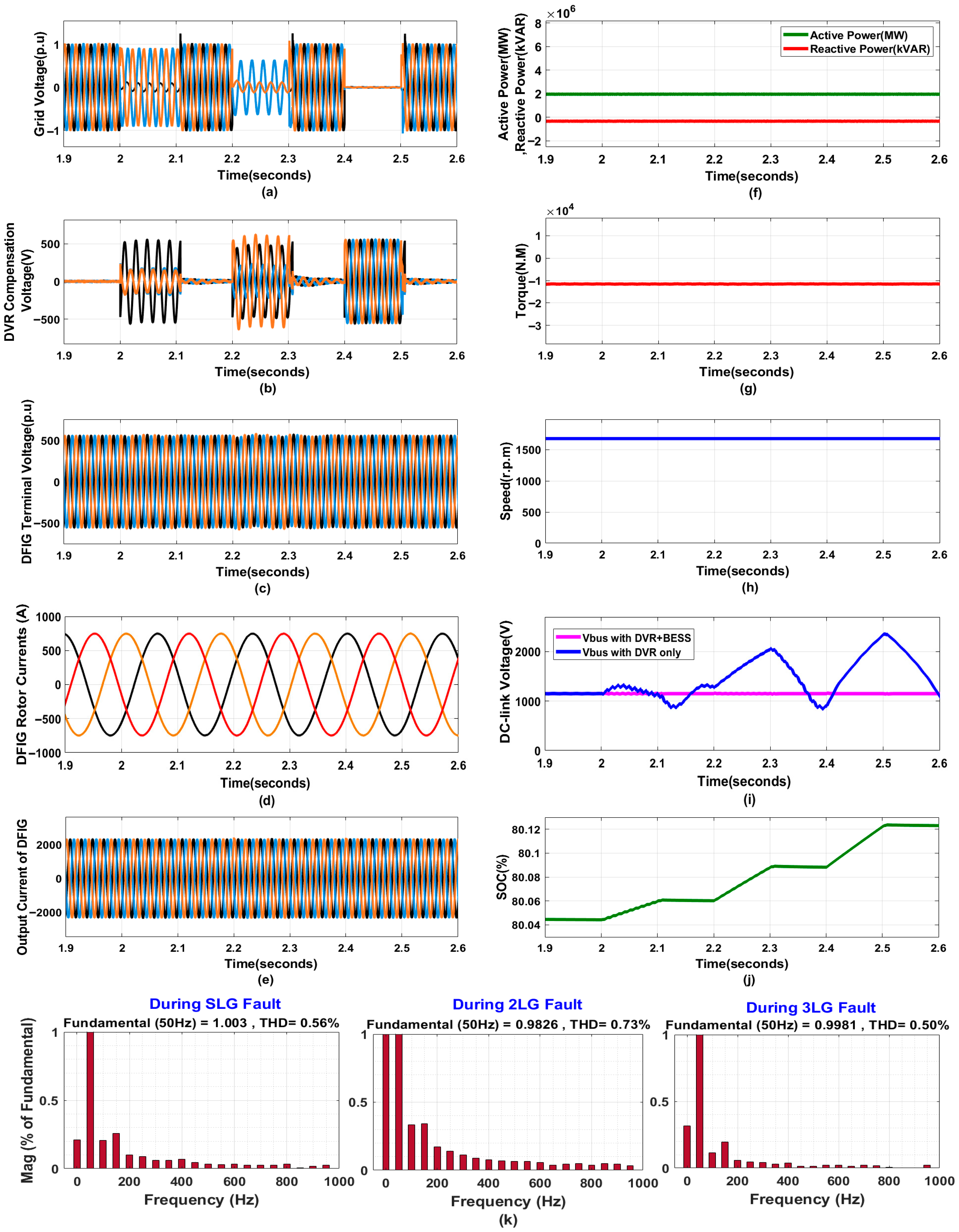
  • Harmonic Reduction: The system achieves excellent harmonic rejection, maintaining Total Harmonic Distortion (THD) levels below 5%, thereby adhering to IEEE standards and improving overall PQ.
The remaining sections of this work are structured as follows. Section 2 provides a brief description and modeling of the studied system, including the sizing of the BESS and DVR. It also examines the dynamic responses of the WES during grid failures. The control schemes for each converter of the studied system are detailed in Section 3. Section 4 discusses simulation findings. Finally, some concluding remarks are presented in Section 5.

2. Configuration, Operation, and Modeling of the Proposed System

Figure 1 illustrates the schematic layout of the proposed WES, highlighting the integration of both the DVR and the BESS. To improve FRT capability and power quality, the DVR is connected in series with the DFIG phases as a flexible power electronic device, with its DC link connected in parallel to the DFIG’s DC bus. The DVR mitigates grid voltage issues by injecting the required voltage at the WES terminal, while the BESS maintains a steady DC-link voltage to ensure proper DVR functionality. The entire system is connected to the main power grid with a Yg/D11 (690 V/25 kV) transformer and a D1/Yg (25 kV/120 kV) transformer and 30 km transmission system. The nominal-Π line configuration denotes the 25 kV line extending 30 km. A 500 kW load is linked to the 690 V line.

2.1. Modeling Equations of the DFIG-WES

2.1.1. DFIG During Normal Operation

Figure 2a,b show the equivalent circuits for the generator and the GSC/RSC in a DFIG system, respectively. The d-axis is aligned with the stator voltage and rotates at the synchronous angular velocity. The performance of the DFIG during normal operation and fault are analyzed using this equivalent circuit. The basic equations of the DFIG referred to stator variables are given in Equation (1) [33].
V s = R s I s + d ψ s d t + j ω s ψ s V r = R r I r + d ψ r d t + j ω s l ψ r ψ s = L s I s + L m I r ψ r = L m I s + L r I r
The subscripts s and r refer to stator and rotor quantities, respectively. Here, V denotes voltage, I represents current, and ψ indicates flux linkage. L stands for inductance, where Lm is the mutual inductance. The slip angular frequency is given by ω s l = ω s ω r , where ω s is the synchronous angular velocity.
Under constant grid voltage, the DFIG maintains steady-state operation with a constant stator flux amplitude [34].
ψ s = L m I m s I m s = L s I s L m + I r
where Ims is the excitation current.
According to Equation (2), the rotor flux and stator current can be determined as follows:
I s = L m L s   I m s + I r ψ r =   L m 2 L s   I m s + σ   L r I r
where σ = 1 L m 2 L s L r   is the leakage flux coefficient. Replacing Equations (3) and (2) into Equation (1), the steady-state voltage can be found as:
V s = R s I s + L m d I m s d t + j ω s ψ s V r = R r I r + σ L r d I r d t + L m 2 L s   d I m s d t + j ω s l ψ r

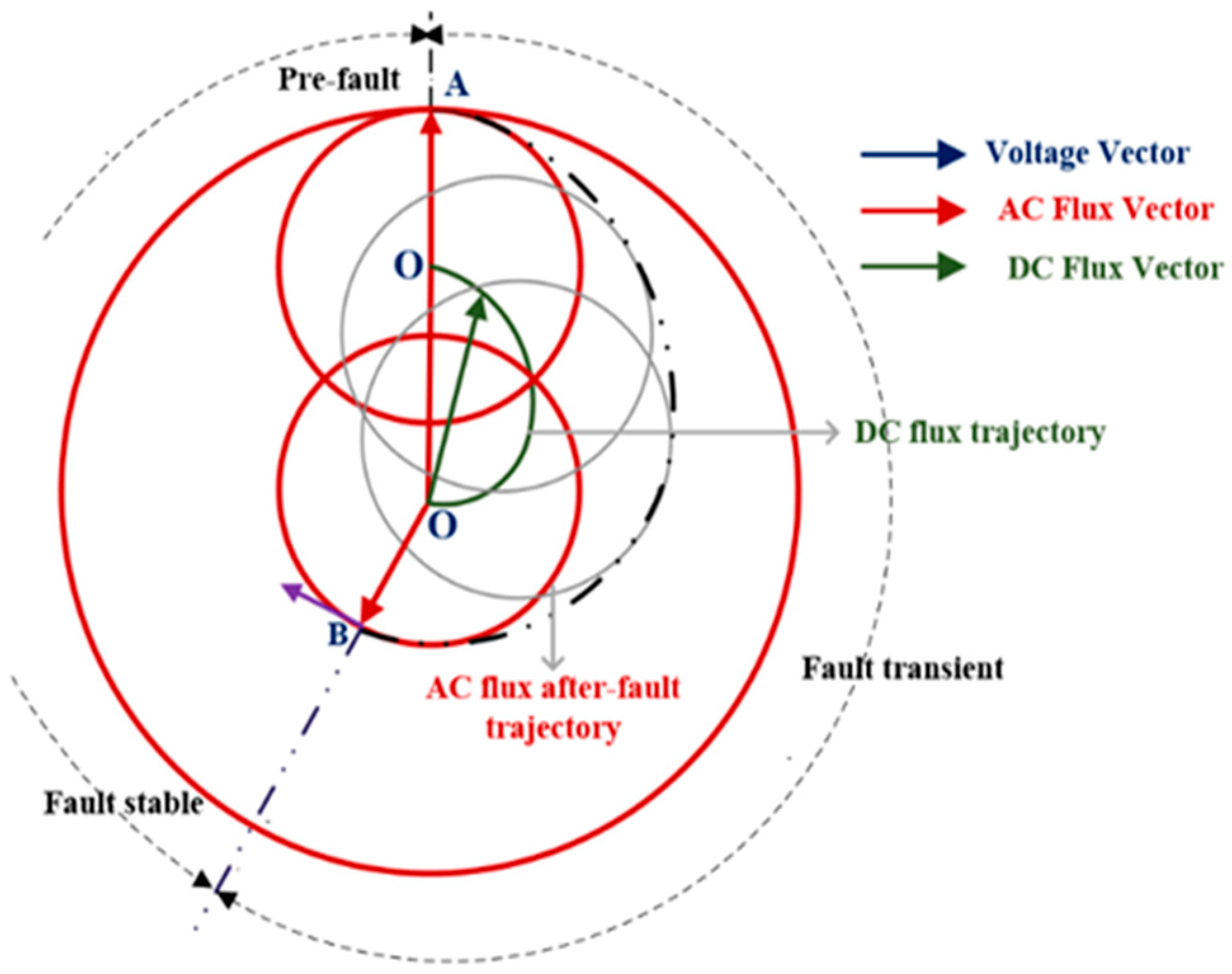
2.1.2. DFIG During Grid Faults

To analyze the behavior of the WES during a grid fault, it is needed to develop a mathematical model. The voltage and flux linkage equations in the stationary αβ reference frame are presented as [35]:
V s α β = R s I s α β + d ψ s α β d t V r α β = R r I r α β + d ψ r α β d t j ω r ψ r α β ψ s α β = L s I s α β + L m I r α β ψ r α β = L m I s α β + L r I r α β
The rotor flux can be offset to rewrite the dynamic rotor voltage as follows:
V r α β = I r α β R r + σ   L r d d t j ω r +   L m L s V s α β R s I s α β j ω r ψ s α β
This formulation isolates rotor leakage dynamics and highlights the coupling influence of stator voltage and flux. Using the steady-state stator flux relation ψ s α β ( t ) = V s j ω s e j ω s t = ψ s e j ω s t , the rotor voltage can be compactly expressed as:
V r α β = I r α β   R r + σ   L r   d d t j   ω r +   L m L s ( s   V s e j ω s t R s I s α β )
In the case of a symmetrical fault, the stator voltage before and after voltage fault can be shown as follows:
V s α β ( t ) = P ( t )   V s   e j ω s t
P ( t ) = 1 , t < 0 1 P , t 0
where P ( 0,1 ) is the voltage drop ratio.
The stator flux evolution can be mathematically determined using the dynamic equation of the stator, given by Equation (5).
d ψ s α β d t = V s α β R s L   ψ s α β
With initial condition initial value of the flux ψ s 0 = V s j ω s e j ω s 0 , solving Equation (9) yields:
ψ s α β ( t ) =   V s j ω s   e j ω s t ,     t < 0     1 P V s j ω s   e j ω s t +     P V s j ω s   e t τ s ,     t 0
Then, the expression of ψ s α β ( t ) at t ≥ 0 can be expressed as:
ψ s α β t = j   1 P ψ s   e j ω s t j P   ψ s   e t τ s ,     t 0
Substituting Equation (11) into Equation (6), neglecting the stator current component, the rotor electromotive force (EMF) refers to the rotor and stator frame under a symmetrical fault.
E r α β s t =   L m L s s 1 P V s   e j ω s t 1 s P V s   e t τ s E r α β r t =   L m L s s 1 P V s   e j ω s l t 1 s P V s     e j ω r t   e t τ s
Under an asymmetrical fault, for t 0 (after fault occurrence), the stator voltage phasor is expressed as:
V s α β   ( t ) =   1 P V s +   e j ω s t   + V s   e j ω s t
where V s + e j ω s t is the positive-sequence fundamental voltage component, reduced by the voltage drop ratio P ( 0,1 ) , and V s e j ω s t is the negative-sequence fundamental voltage component introduced by the asymmetrical fault.
Before the fault (t < 0), the negative-sequence component is zero, and the voltage is balanced. The dynamics of the positive and negative sequence fluxes can be described as:
d ψ s + d t = ( 1 P ) V s + e j ω s t R s L ψ s + d ψ s d t = V s e j ω s t R s L ψ s
with initial conditions ψ s + 0 = V s + j ω s e j ω s 0 , ψ s 0 = 0 ; solving Equation (3) yields:
ψ s α β t =   V s + j ω s   e j ω s t ,     t < 0     1 P V s + j ω s   e j ω s t +   V s j ω s   e j ω s t ,     t 0
The rotor EMF can be expressed as:
E r α β r t =   L m L s s 1 P V s +   e j ω s l t + 1 s ( P V s + + V s ) e j ω r t   e t τ s + 2 s   V s e j ( 2 s ) ω s t
The rotor EMF is composed of three components, as indicated in Equation (16). This shows that the transient rotor EMF significantly increases compared to normal operating conditions, considering that the slip typically ranges between −0.2 and 0.2. The gearbox and RSC undergo substantial stress, with potential damage caused by fluctuations in the rotor current and torque due to the overvoltage in the rotor EMF. Figure 3 explains the dynamic behavior of the stator flux under fault conditions. During normal operation, the flux rotates alongside the exterior circle. During a three-phase voltage sag at point A, the stator flux fails to preserve its initial magnitude because the magnetic field cannot adapt immediately. Consequently, the flux separates into two distinct components: a rotating AC component aligned with the synchronous reference frame (AO’) and a stationary DC component (OO’). Following the fault, the synchronously rotating flux vector’s source is substituted with a passive DC flux vector (OO’), which gradually decays along the green trajectory. Once the disturbance subsides at Point B, the transient ends, and the AC flux vector resumes rotation along a smaller red inner circle [36]. The fault-driven inrush current in the rotor increases active power and raises the DC-link voltage, leading to severe oscillations in the EMT, which can cause damage to the DFIG.

2.2. Grid Code Requirements

A grid code defines the mandatory operational behavior of connected generators during disturbances, including specifications for power factors, reactive power support constraints, and voltage regulation [37]. The FRT profile, as specified by E.ON, a European utility, is depicted in Figure 4a, outlining requirements for Zero-Voltage Ride-Through (ZVRT), HVRT, and LVRT. The FRT mechanism must engage within 200 ms when voltage drops below 0.9 per unit (pu). For voltages between 0.9 and 0.5 pu, the WES must supply 2% reactive current per 1% voltage decrease. Below 0.5 pu, the system is required to supply 100% reactive current to stabilize the grid [38]. Figure 4b illustrates the reactive current delivered by the WES to stabilize the voltage whenever it deviates beyond a ±10% tolerance from the nominal level. Outside this range, the reactive current is controlled based on the formula provided in [39]:
I q I q 0 2 I n V V 0 V n
where I q 0 represents the reactive current prior the fault; Iq is the reactive current; In = 1 pu is the nominal current; V 0 is the voltage before the fault; V is the present voltage; Vn = 1 pu is the nominal value.

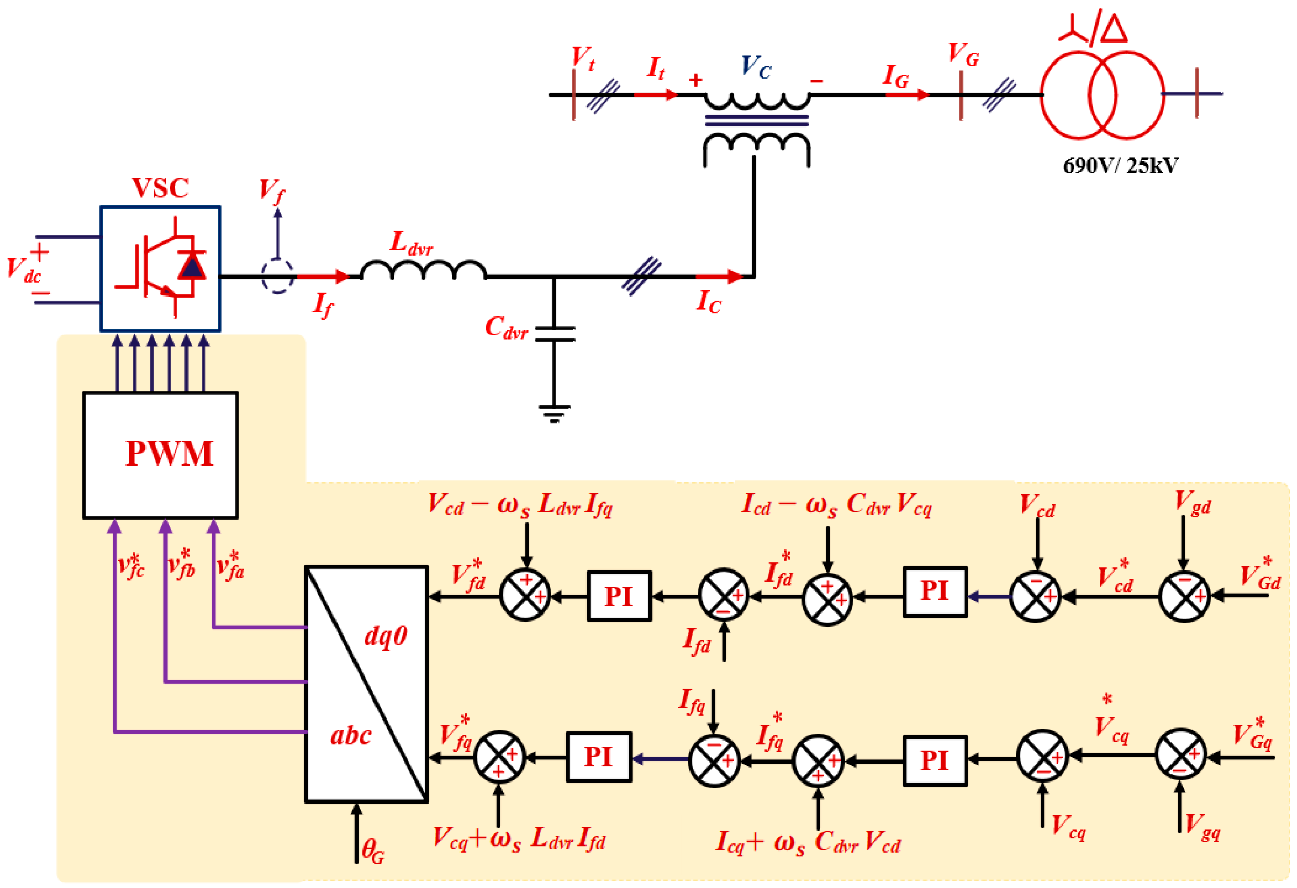
2.3. DVR Model and Design
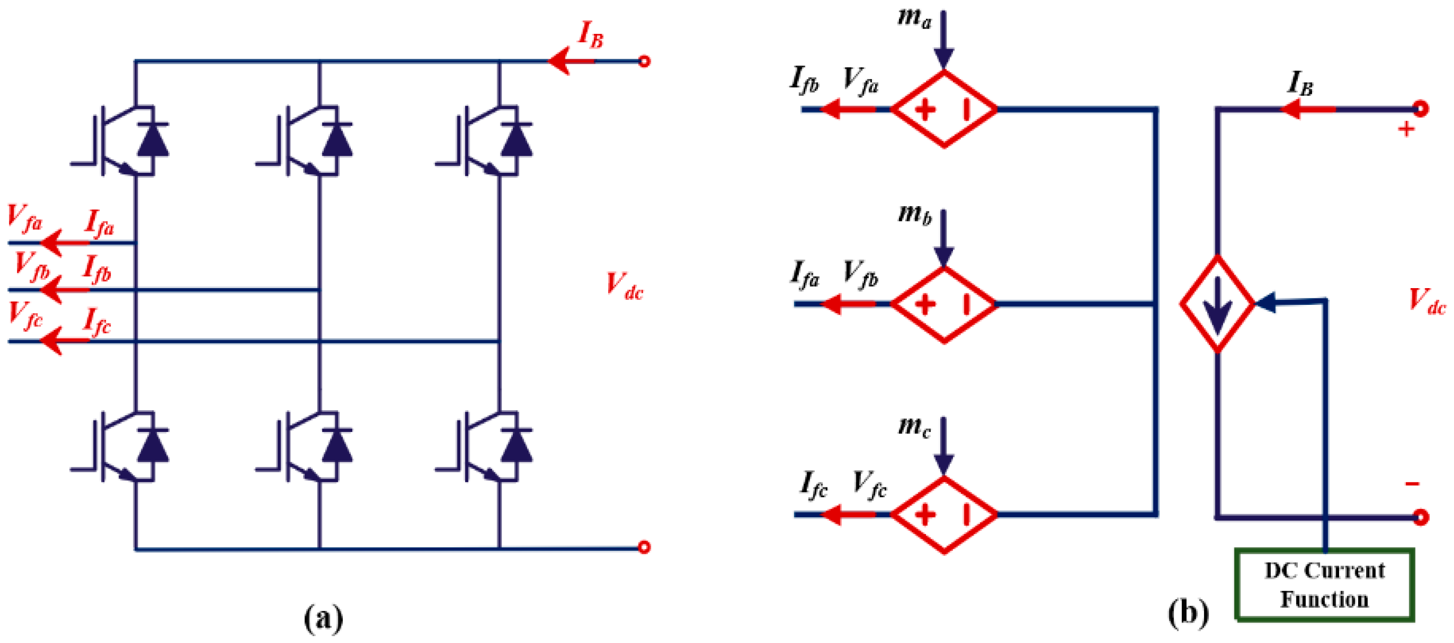
2.3.1. DVR Model

In the examined system, the DVR is implemented as a voltage source converter (VSC) linked in series with the WES terminals through three single-phase transformers, allowing for the swift mitigation of grid voltage disturbances. Moreover, the DC link of the DVR is parallel with the DC bus of both WES and BESS. An essential component of the DVR is the filter, which plays a key role in minimizing the THD in the voltage output from the VSCs. Figure 5 depicts the typical structure of a two-level VSC. The AC-side three-phase current and voltage of the DVR-side converter (DSC) are represented by Ifabc and Vfabc, respectively.
In Figure 5b, Vfa, Vfb, and Vfc represent the three-phase voltage Vfabc, which depends on the modulation indices ma, mb, and mc [29]:
V f i = 0.5 m i V d c , i = a , b , c
Assuming that the DVR is lossless, active power balance gives
I B = 0.5 i = a c m i   I f i
Assuming that the interface transformer is ideal, the current/voltage relationships between the primary/secondary can be expressed as follows [41]:
V c = V t V G I c = I g
where Vc represents the compensation value and VG and Vt denote the terminal voltage of the WES and grid voltage, respectively.
The LC filter’s mathematical model is formulated as follows [40]:
V f = L d v r d I f d t + V c I f = C d v r d V c d t + I c
where If and Ic denote the DVR-generated current and compensation current, respectively, and Ldvr and Cdvr are the parameters of the LC filter.

2.3.2. DVR Parameters Design

In the design of a DVR, proper sizing of the DC-link storage system and the output filter is crucial for effective voltage compensation and power quality improvement. The DC-link voltage magnitude, Vdc, is determined by:
V d c = 2 2 V L L 3 m
where V L L is the line-to-line voltage of the three-phase system and m is the modulation depth, typically set to 1.
A V L L = 690 V system with m a = 1 requires a V p h 398   V , V p h , p e a k 563   V , leading to a minimum V d c 1126   V .
The stored energy in the DC-link capacitor (Es) is given by:
E s = 1 2 C d c V d c 2
where V d c is the rated DC-link voltage and C d c is the capacitance of the DC-link capacitor.
The apparent power rating of the DVR (SDVR) depends on the load current ( I load   ) and the injected voltage
S D V R = 3 × V i n j × I l o a d
The LC filter is essential for smoothing the inverter output voltage and reducing switching harmonics. It is designed to maintain the THD within standard limits. The resonance frequency of the LC filter, f r , should be greater than the system frequency, f n , and less than the PWM switching frequency, f p s w , i.e.,
10 f n f r = 1 2 π L C M f p s w
In Equation (25), the range of M is from 0.1 to 0.5. To minimize both the cost and size of the DVR filter, the capacitor should be chosen in a way that meets the application requirements while keeping these factors in check.

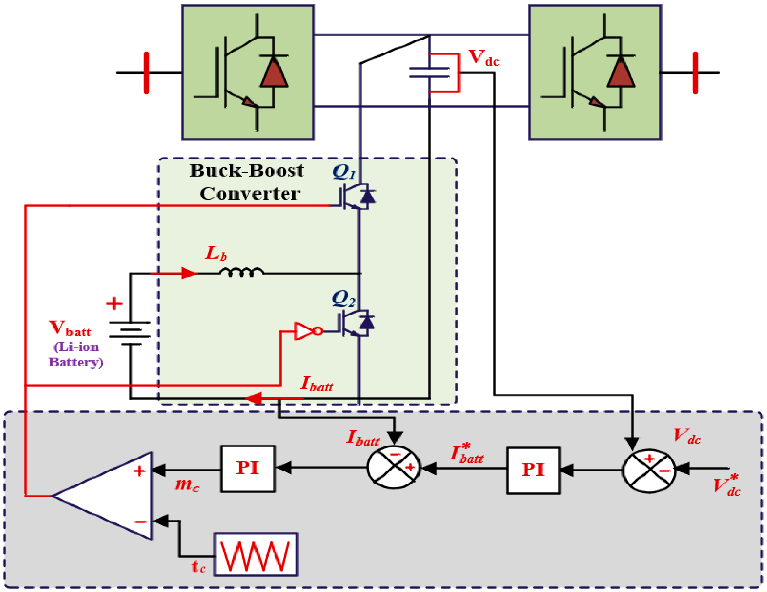
2.4. Battery Energy Storage System Model

2.4.1. Battery Modeling

The deployment of a BESS is vital for facilitating the stable integration of renewable sources into the grid by mitigating the fluctuations resulting from their intermittent output. The concept involves utilizing a BESS to accumulate surplus energy during periods of low grid demand and subsequently discharging this stored energy during periods of high demand. This ensures a consistent and reliable electricity supply to properly accommodate varying grid demands. Figure 6 presents the Li-ion battery model utilized in this research [40].
The battery model, encompassing both charging/discharging events, is expressed in Equation (26).
Discharge   model   for   I * > 0 : f 1 I t , I * , I = E 0 K Q Q I t I * K Q Q I t I t + A e B × I t Charge   model   for   I * > 0 : f 2 I t , I * , I = E 0 K Q I t 0.1 Q I * K Q Q I t I t + A e B × I t
In this equation, I * and I represent the low-frequency current and the battery current, respectively; E 0 is the constant voltage; Q is the nominal capacity (Ah); K is the polarization constant (Ω); and A and B correspond to the exponential voltage and capacity (Ah−1), respectively.

2.4.2. DC/DC Converter Modeling

The integration of a BESS with a WES has gained significant attention to enhance grid compatibility and improve system performance. Integrating a BESS into the DC link contributes to power stabilization and enhances system stability through the use of a bidirectional converter, which plays a crucial role in managing the BESS and ensuring maximum power transfer between the BESS and the DC link. The main objective of the bidirectional converter is to stabilize the voltage and power requirements of the DC-link and to handle the transfer of power to and from the BESS [42]. The bidirectional converter charges the BESS, which facilitates its storage, when there is surplus power. BESS discharge is necessary to supply power to the DC voltage during periods of excessive demand. This approach enhances system grid stability, efficiency, and PQ by mitigating the impact of sudden fluctuations. The BESS’s capacity to quickly supply or absorb power during these fluctuations is essential for maintaining grid stability [43]. In this study, a buck–boost bidirectional DC-DC converter is utilized to establish the connection between the proposed BESS and the DC link of the DFIG, as depicted in Figure 7. The converter operates in two modes—buck and boost—selected by the switching modes [44].
During the charging process, the Q1 switch and Q2 diode transfer energy from the DC link to the BESS. The Q1 switch activates the body diode of the Q2 switch when it is ON, while the Q2 switch is OFF, as illustrated in Figure 7a, and the current passes from the high-voltage (HV) to the low-voltage (LV) side of the circuit through the inductor. In the event that the battery discharges, the Q2 switch and Q1 diode supply energy to the DC-link, preventing the Q1 switch from working, and the converter functions as a unidirectional converter, as illustrated in Figure 7b. During boost mode, the inductor current transfers energy from the LV to the HV side. Notably, the battery’s output voltage rises while charging and drops during discharge [45].

2.4.3. Parameter Design of BESS and DC/DC Converter

The voltage (Vbattery) and current (Ibattery) of the BESS are determined based on the power requirement (Pbattery):
I b a t t e r y   = P b a t t e r y   V b a t t e r y  
For a 600 kW BESS with a battery voltage Vbattery = 600, the current is calculated as:
I b a t t e r y   = 600,000 600 = 1000   A
The energy capacity (Ebattery) of the BESS is dependent on the discharge time (tdischarge), as expressed by the following equation:
Ebattery = Pbattery · tdischarge
A bidirectional buck/boost converter interfaces the BESS ( V b a t t e r y   ) with a DC link ( V d c   ). The duty cycle (D) in each mode is given by:
Boost mode (discharging):
D b o o s t = 1 V b a t t e r y V d c  
Buck mode (charging):
D b u c k = V b a t t e r y V d c  
For V b a t t e r y   = 600   V and V d c _ l i n k   = 1150   V :
D b o o s t   = 1 600 1150 0.478 ,   D b u c k   = 600 1150 0.522
The inductance (L) of the converter is chosen to limit the current ripple (ΔIL) to 10–30% of the Ibattery. The inductance is calculated using the following expression:
L = D V b a t t e r y Δ I L f s w
where f s w is the switching frequency.
For Δ I L = 20 % × 1000   A = 200   A and f s w = 20   k H z
L = 0.478 600 200 20,000 71.7   μ H
The output capacitance (C) is required to limit the voltage ripple (ΔVout) of the system. The capacitance is calculated using the following formula:
C = Δ I L 8 f s w Δ V o u t
For a voltage ripple ΔVout = 1% × 600 V = 6 V, the required output capacitance is:
C = 200 8 20,000 6 208   μ F
This approach ensures that the system can effectively regulate both current and voltage ripple, thereby maintaining the desired performance and stability of the BESS during operation.

3. Control Schemes for Studied System

Figure 8 displays the control approaches for each converter in the DFIG-based WES coupled with the DVR and BESS. The GSC and RSC of the DFIG use traditional vector control approaches. The DVR and BESS converters maintain the DFIG terminal and DC bus voltages. This section discusses the control strategies for each converter as follows:

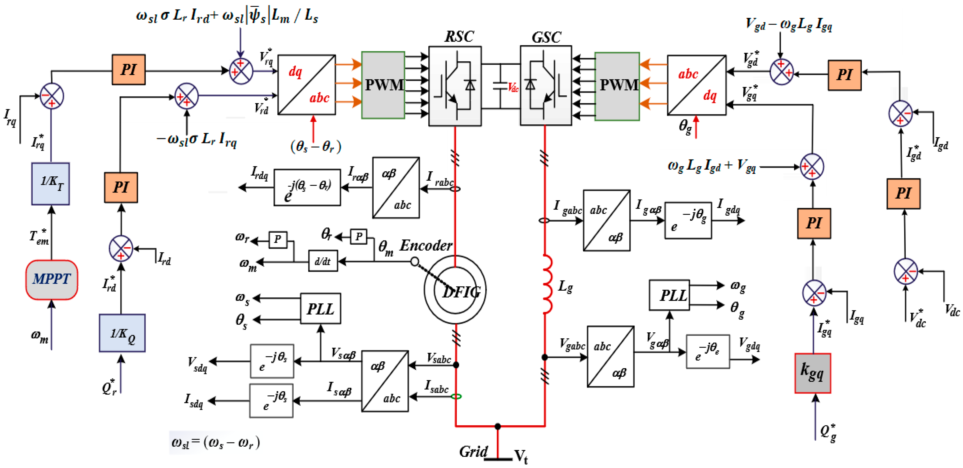
3.1. Control of Back-to-Back Converters

The control schemes of the back-to-back converters with the PI controller are shown in Figure 8. The aim of the RSC control is to obtain Maximum Power Point (MPP) and control the reactive power supplied by the DFIG. The torque reference obtained by a MPPT is used to create the q-axis rotor current reference ( I r q * ), which is compared with the q-axis rotor current (Irq) to provide the q-axis voltage signal (Vrq) through the PI controller. The reference of the d-axis rotor current ( I r d * ) can be obtained from the reactive power control loop. The reference reactive power is equal to zero ( Q s * = 0 ). The ( I r d * ) is compared with the d-axis rotor current to obtain the d-axis voltage signal (Vrd) through the PI controller. After decoupling, the dq-axis voltage references V r q * and V r d * are obtained, respectively. The angle (θs − θr) is used in a park transformation to generate signals through the switch gate utilizing the PWM carrier wave for rotor-side VSC switches [46].
On the other side, the main task of the GSC is to maintain a constant DC-link voltage and provide a specific reactive power independent of the rotor power flow’s direction and magnitude. A PI controller regulates the DC-link voltage. The reference of the d-axis grid current (I*gd) obtained from the DC voltage controller is compared with the measured current (Igd) to generate the d-axis voltage (Vgd), while the reactive power flow is controlled by the q-axis grid current (I*gq), which is compared with the measured current (Igq) to generate the q-axis voltage (Vgq). Compensation terms are added to Vgd and Vgq to somewhat decouple the DC-link voltage regulation from the reactive power regulation. A phase-locked loop (PLL) detects the park transformation angle (θg) from three-phase voltages on the low-voltage side of the grid transformer. Finally, grid-side PWM is used to generate gate signals for grid-side VSC switches [47].

3.2. Control of DVR

The DVR operates to swiftly mitigate grid disturbances and preserve the WES’s phase voltage at the desired level. The q-axis and d-axis components, derived from the d-q reference frame, are Vtdq, VGdq, Vcdq, Vfdq, Icdq, and Ifdq. Assuming that the voltage of the grid is aligned to the d-axis, i.e., VGq = 0, VGd = VG. The injected compensation voltage Vc can be obtained from the difference between the WES’s terminal voltages Vt and grid voltage VG.
The compensating voltage reference across the transformer can be represented in the dq-reference as follows [48]:
V c d * = V t d * V G d V c q * = V t q * V G q
V t d * and V t q * refer to the dq pre-sag terminal voltages, while V G d and V G q refer to the voltages after the occurrence of a voltage sag, and the superscript “*” indicates the reference values. The modeling of the DSC can be written as follows, taking into account the LC filter.
V f d = L d v r d I f d d t ω s L d v r I f q + V c d V f q = L d v r d I f q d t + ω s L d v r I f d + V c q I f d = C d v r d V c d d t ω s C d v r V c q + I c d I f q = C d v r d V c q d t + ω s C d v r V c d + I c q
Using the PI controller relationship between several components, the reference output signals of the DVR in the dq axis can be obtained as follows:
V f d * = K p d f + K i d f 1 s I f d * I f d ω s L d v r I f q + V c d V f q * = K p q f + K i q f 1 s I f q * I f q + ω s L d v r I f d + V c q I f d * = K p d c + K i d c 1 s V c d * V c d ω s C d v r V c q + I c d I f q * = K p q c + K i q c 1 s V c q * V c q + ω s C d v r V c d + I c q
After determining the DSC reference voltages in the dq synchronous frame, they are transformed into the stationary system to facilitate the generation of switching signals for the DVR’s VSC using PWM carrier modulation as shown in Figure 9.

3.3. Control of DC/DC Converter

This converter can be employed to achieve quick bidirectional energy transfer between the battery of the ESS and the WES’s DC bus. The control aim is to maintain the DC-link voltage Vdc constant. Figure 10 shows how two cascaded control loops generate PWM pulses for switches Q1 and Q2. The voltage controller processes the deviation between the actual DC bus voltage Vdc and its reference value V*dc, producing a reference current I*batt. The difference between I*batt and Ibatt enters the PI current controller, and the modulating signal (mc) is obtained, which compared with triangular signal (tc) for generating the PWM pulses of switches Q1 and Q2. The control modulating signal (mc) and the reference battery current can be expressed as a function of PI controller gains [42].
I b a t t * = V d c * V d c K p d c c + K i d c c 1 S m c = I b a t t * I b a t t K p b a t t + K i b a t t 1 S
where Kpdcc and Kidcc are the gain values of the outer voltage control loop, and Kpbatt and Kibatt are the gain values of the inner current control loop.

4. Simulation Results and Discussion

This section assesses the effectiveness of the proposed protection strategy in improving the resilience of DFIG-based WESs under grid disturbance conditions. The complete system is modeled using the SimPowerSystems toolbox in MATLAB/Simulink 2024b. The simulation parameters are listed in Table 1. The 2 MW DFIG is integrated into a 25 kV distribution system and delivers power to a 120 kV transmission grid. The generator operates at nominal power under a wind speed of 12 m/s, employing field-oriented control for both the rotor- and grid-side converters. Under steady-state conditions, the DC-link voltage is maintained at 1150 V. Simulations are conducted to evaluate DFIG performance both without protection and with the proposed BESS-DVR system under various PQ disturbances as described below:

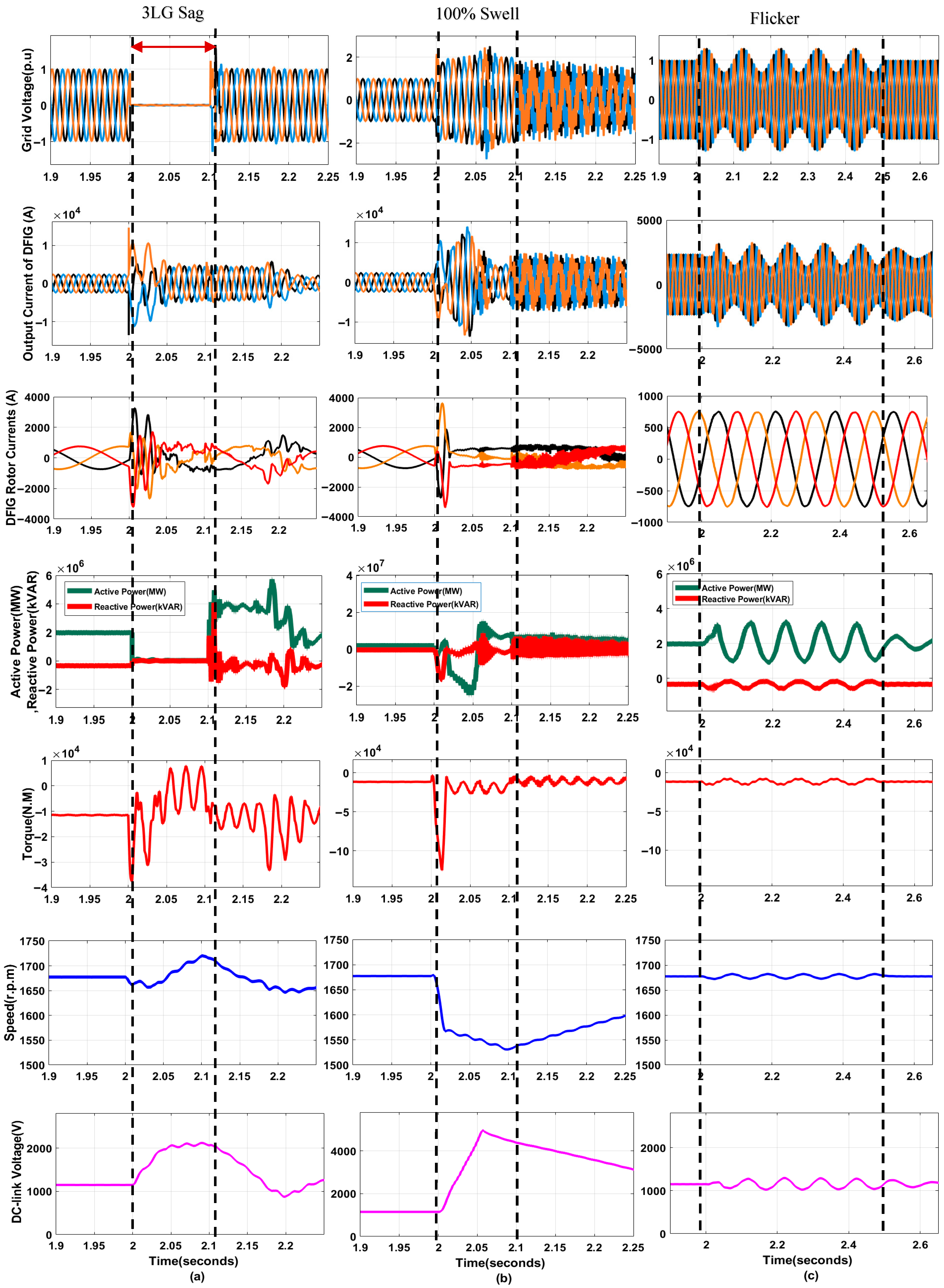
4.1. DFIG Behaviors Without Protection

The simulation results without the protection approach are presented to illustrate the effects of voltage sags, swells, and flicker on the circuit configuration. The parameter responses (grid voltage, rotor and output currents, output powers, EMT, generator speed, and DC-link voltage) under each of these conditions are shown in Figure 11. As seen in Figure 11a,b, the unbalanced network voltage had a direct effect on stator voltages. The stator current increased during voltage sag/swell. Furthermore, because of the change in the stator flux, the rotor currents had a dangerous peak to reach values. These oscillations subjected the RSC to extreme stress, which is unacceptable since it has a major impact on the RSC and may cause damage. The decrease in the generator output voltage caused a significant drop in the active power, resulting in zero power exchange between the generator and the system. Also, active power and reactive power presented significant fluctuations during swell events. The variation in generated active power led to noticeable oscillations in the EMT. The EMT showed substantial oscillation. Such oscillations can adversely affect the mechanical components of the generator and the turbine blades. Figure 11a,b illustrate how faults affect the speed of the WES. During a voltage sag, the speed rises to offset the reduction in active power, while during a swell, the mechanical speed drops to accommodate the increase in power output. It is noted that the DC-link voltage exceeds 4000 V during a voltage swell. As shown in Figure 11c, flicker has a smaller effect on the DFIG compared to voltage sags and swells. However, maintaining the protection of the DFIG and ensuring PQ for sensitive loads remain crucial and must be managed with precision.

4.2. DFIG Behaviors with Protection

A 2 MW WES with an integrated DVR and BESS has been developed and modeled. The BESS has a capacity of 0.5 MW/120 kWh, with an initial state of charge (SOC) of 0.8. To investigate the function of the DVR and BESS, four scenarios are studied. The buck/boost converter is designed to give a continuous constant DC voltage to the DVR, enabling the generation of a precise sinusoidal voltage. This study evaluates the PQ and FRT capabilities of the DFIG with the proposed protection system by considering four distinct disturbances, as follows:

4.2.1. Multiple Voltage Sags

Figure 12 illustrates the impact of voltage sags on the power system. Multiple voltage sags occur at 2 s and 2.2 s, causing a 1 PG fault and a 2 PG fault with 0.1 s duration, respectively. Additionally, a symmetric voltage sag at a 100% depth of a 3 PG fault appears at t = 2.4 s, as shown in Figure 12a. The wind speed is assumed to remain constant throughout the analysis, with a fixed value of 12 m/s. During a voltage drop event, a DFIG is required to remain connected for a specific time duration before disconnection is permitted. This requirement enhances the stability of the power network, as the abrupt disconnection of the DFIG could adversely affect the overall stability of the power system. Figure 12b shows the response of the proposed DVR, which penetrates the system to compensate for voltage sag events and improves both the LVRT and PQ capabilities.
Under asymmetric conditions, the DVR injects appropriate unbalanced three-phase positive voltage components to mitigate voltage imbalances. Conversely, for symmetric conditions, the DVR injects equal positive-sequence voltage components across all three phases, aligned in phase with the supply voltage, to restore voltage levels and maintain stability. The parameter responses of the DFIG under this disturbance are presented in Figure 12c–i. As illustrated in Figure 12c, with the protection scheme provided by the proposed approach, the DFIG terminal voltage is rapidly stabilized by the AC-side DVR, eliminating oscillations both during and after the fault. Figure 12d,e show that the stator and rotor currents are limited to their rated values during three types of faults, and they demonstrate excellent response when faults are cleared. Since the DVR keeps a fix voltage, the active power exchanged by the DFIG is maintained constant at its rated value of 2 MW, and the reactive power is kept constant, as shown in Figure 12f. It can be noted from Figure 12g that the proposed DVR based strategy is valid for eliminating the destructive pulsations in EMT. The mechanical speed is quite immune to disturbances during sag events, as shown in Figure 12h.
From Figure 12i, the DC-link voltage shows no oscillations during the occurrence and clearance of the fault when both a BESS and a DVR are used, proving that the proposed protection system successfully removes excess power and maintains the DC voltage within its permissible limits. In contrast, there is significant rise and fluctuation in the DC-link voltage with the DVR only, as the DVR cannot effectively stabilize the DC-link voltage during faults due to its inability to manage power imbalances. Since the DVR is fed from the DC-link voltage of the generator, the role of the BESS is to absorb or inject energy, ensuring that the voltage stays within permissible limits. The SOC of the battery is given in Figure 12j. During grid fault conditions, the excess energy accumulated in the DFIG DC bus can be absorbed into the battery via the DC/DC converter. Thus, the rate of growth accelerates, and the BESS keeps the DC-link voltage Vdc stable and prevents it from rising even during an asymmetrical severe grid fault. As explained in Figure 12k, all the THD values of voltage harmonics in the DFIG terminal voltage during voltage disturbance are restrained lower than 0.73%. With voltage perfectly compensated, using the proposed DVR keeps the THD lower than 5%, as advised by IEEE Standard 519.

4.2.2. Multiple Voltage Swells

The performance of a proposed WES integrated with a DVR and BESS under multiple consecutive voltage swell events has been analyzed, with the corresponding results illustrated in Figure 13. The primary causes of swells include the energization of capacitor banks, the shutdown of large loads, unbalanced faults (which cause an increase in one or more phase-to-phase voltages), transients, and power frequency surges. The effects of swells are generally similar to those of voltage sags. The severity of the voltage swell can vary depending on the characteristics and extent of the inductive loads involved. Two voltages swells are applied to the system; the first is an asymmetric voltage swell, applied at t = 2 s with a duration of 0.2 s, and the second is a symmetric voltage swell of 100%, applied at t = 2.3 s with a duration of 0.2 s (with the wind speed constant at 12 m/s), as shown in Figure 13a. Once the disturbance is detected, the DVR plays a key role in compensating for the incident, absorbing excess energy from the grid during both asymmetric and symmetric voltage swell events. It delivers the necessary three-phase voltage so that the DFIG follows its nominal power generation, as indicated in Figure 13b. The injected voltage is out of phase with the grid voltage, which maintains the desired voltage amplitude at the stator. So, the terminal voltage of the DFIG is kept constant at a normal value, as shown in Figure 13c. The rotor current and the output current of the DFIG are not changed, as shown in Figure 13d,e. Also, the active power produced by the DFIG maintains its output of 2 MW, while the reactive power remains constant, as it was before the disturbance occurred, as shown in Figure 13f.
Figure 13g,h illustrate the behavior of the mechanical quantities, rotor speed, and EMT, respectively. Also, no oscillations are shown in the graph of the EMT during the fault. As shown in Figure 13i, the proposed scheme effectively mitigates the DC-link over-voltage, maintaining it at a constant 1150 V. Again, the combination of a DVR and a BESS effectively stabilizes the DC-link voltage, compared to the scenario with a DVR alone, where the voltage undergoes significant fluctuations. This highlights the superior performance of the DVR + BESS combination in maintaining voltage stability during grid disturbances. The state of charge (SOC) of the Li-ion battery, depicted in Figure 13g, decreases during voltage swell events as the battery discharges to stabilize the DC-link voltage. Despite significant grid disturbances, the DC-link voltage remains largely unaffected due to the combined compensation from the BESS and DVR. The THD during compensation is obtained as 0.42%, as illustrated in Figure 13k, which improves the capability of the proposed DVR to enhance HVLT with a THD lower than 5%, as advised by the IEEE Standard.

4.2.3. Voltage Flicker

The flicker disturbance might come from pulsating loads like arc furnaces, compressors, and welding machines. Additionally, voltage drops due to the impedance of the network source, coupled with changes in load current from various equipment and facilities, can significantly contribute to its occurrence. It can have damaging consequences for delicate electronic devices and industrial applications that rely on a steady power supply. Moreover, when substantial flicker sources are linked to the system with DFIG, the FRT like the voltage profile at the generator and DC-link could trigger the protection scheme to disconnect the DFIGs from the grid. The proposed DVR effectively and rapidly compensates for this voltage disturbance.
To assemble voltage flicker, oscillations of magnitude with ±3% p.u and 10 Hz frequency are added to the grid voltages at t = 0.2 s and removed at t = 2.5 s, as shown in Figure 14a. As seen in Figure 14b, the DVR can promptly identify fluctuations and inject the three appropriate single-phase voltages to alleviate voltage flicker. So, the compensated voltage remains sinusoidal due to the compensation value provided by the VSC of the integrated DVR, as illustrated in Figure 14c.
As shown in Figure 14d–f, the rotor and output currents, along with the active and reactive powers, are effectively illustrated and analyzed. Figure 14g,h display the mechanical quantities of the DFIG, including rotor speed and EMT, both of which remain stable during the disturbance. This stability is attributed to the effective operation of the DVR and BESS, which maintain the DC-link voltage at a constant level, as shown in Figure 14i. These results confirm that the proposed protection strategy successfully mitigates flicker disturbances, achieving a THD of 0.41%, as illustrated in Figure 14j.

4.2.4. Voltage Harmonics

In this scenario, the effectiveness of the proposed DVR was tested under harmonic conditions. Voltage harmonics, caused by large nonlinear loads or equipment failures, distort the ideal sinusoidal voltage waveform, introducing harmonics into the supply voltage. The programmable voltage source was configured to include third harmonic components, with the voltage variation occurring between 2 and 2.5 s, as shown in Figure 15a. This results in a distorted grid voltage waveform with noticeable swell, which can impair or damage the DFIG.
To ensure that the THD remains within IEEE standards and to improve PQ, the DVR swiftly injected corrective voltage into the distribution line, counteracting the disruptive voltage disturbance and allowing the DFIG to operate normally. The injected voltage across all three phases is presented in Figure 15b. The compensation of the DFIG terminal voltage is evident across all three phases, with voltage swells and high-magnitude harmonics eliminated, restoring the voltage profile to its normal state, as shown in Figure 15c. As observed in Figure 15d–h, other parameters (rotor and output current, output active and reactive power, EM torque, and rotor speed) of the DFIG demonstrate excellent responses. They are constrained within their rated values because the DVR isolates the DFIG from the grid during voltage disturbance. A slight ripple is generated in the DC-link voltage when the voltage harmonic occurs, as depicted in Figure 15i. The THD percentage is around 0.4%, as illustrated in Figure 15j.

5. Conclusions

This work proposed a novel protection approach for a DFIG-based WES by integrating a DVR at the WES terminals and a BESS at the DC-link. The main goal was to enhance the FRT capability and PQ of the WES under different grid disturbances, including sags, swells, flickers, and harmonics. The DVR compensates for voltage anomalies on the AC side, while the BESS helps stabilize the DC-link voltage by absorbing or supplying power as needed. Simulation results confirmed that the proposed approach effectively mitigates the negative impacts of disturbances, maintaining stable rotor and output currents, active and reactive powers, electromechanical torque, and mechanical speed. The DC-link voltage was kept at 1150 V without oscillations, even during severe faults. The system also demonstrated strong harmonic suppression capabilities, reducing the THD to 0.73% during voltage sags, 0.42% during swells, 0.41% during flicker, and 0.4% during harmonic events—all within IEEE 519 standards. These results emphasize the feasibility and efficiency of the DVR-BESS scheme in enhancing the stability and grid compatibility of wind farms. Future research can focus on optimizing control strategies, validating the system through hardware implementation, and assessing the economic viability and scalability for offshore wind applications.

Author Contributions

Conceptualization, A.M.N., A.K.A. and A.A.A.-S.; Methodology, A.M.N. and A.K.A.; Formal analysis, A.M.N. and H.M.H.F.; Investigation, A.M.N. and A.A.A.-S.; Resources, A.K.A. and H.M.H.F.; Writing—original draft, A.M.N., A.K.A. and A.A.A.-S.; Writing—review & editing, A.K.A. and H.M.H.F.; Project administration, H.M.H.F. and A.K.A.; Funding acquisition, A.A.A.-S. All authors have read and agreed to the published version of the manuscript.

Funding

This work was supported and funded by the Deanship of Scientific Research at Imam Mohammad Ibn Saud Islamic University (IMSIU) (grant number IMSIU-DDRSP2503).

Data Availability Statement

Data are contained within the article.

Conflicts of Interest

The authors declare no conflict of interest.

References

  1. Hadi, H.A.; Kassem, A.; Amoud, H.; Nadweh, S.; Ghazaly, N.M.; Moubayed, N. Using Active Filter Controlled by Imperialist Competitive Algorithm ICA for Harmonic Mitigation in Grid-Connected PV Systems. Int. J. Robot. Control Syst. 2024, 4, 581–605. [Google Scholar]
  2. Abdulabbas, A.K.; Alawan, M.A.; Shary, D.K. Limits of reactive power compensation of a doubly fed induction generator-based wind turbine system. Bull. Electr. Eng. Inform. 2023, 12, 2521–2534. [Google Scholar]
  3. Hassan, Q.; Algburi, S.; Sameen, A.Z.; Salman, H.M.; Jaszczur, M. A review of hybrid renewable energy systems: Solar and wind-powered solutions: Challenges, opportunities, and policy implications. Results Eng. 2023, 20, 101621. [Google Scholar]
  4. Ravi, T.; Kumar, K.S.; Dhanamjayulu, C.; Khan, B.; Rajalakshmi, K. Analysis and mitigation of PQ disturbances in grid connected system using fuzzy logic based IUPQC. Sci. Rep. 2023, 13, 22425. [Google Scholar]
  5. Amalorpavaraj, R.A.J.; Palanisamy, K.; Umashankar, S.; Thirumoorthy, A.D. Power quality improvement of grid connected wind farms through voltage restoration using dynamic voltage restorer. Int. J. Renew. Energy Res. 2016, 6, 53–60. [Google Scholar]
  6. Qasim, A.Y.; Tahir, F.R.; Alsammak, A.N.B. Voltage Sag, Voltage Swell and Harmonics Reduction Using Unified Power Quality Conditioner (UPQC) Under Nonlinear Loads. Iraqi J. Electr. Electron. Eng. 2021, 17, 140–150. [Google Scholar]
  7. Yuan, L.; Meng, K.; Huang, J.; Dong, Z.Y.; Zhang, W.; Xie, X. Development of HVRT and LVRT control strategy for PMSG-based wind turbine generators. Energies 2020, 13, 5442. [Google Scholar] [CrossRef]
  8. Adware, R.; Chandrakar, V. Power quality enhancement in a wind farm connected grid with a fuzzy-based STATCOM. Eng. Technol. Appl. Sci. Res. 2023, 13, 10021–10026. [Google Scholar]
  9. Delavari, H.; Sharifi, A. Adaptive fractional order control of doubly fed induction generator based wind energy conversion system under uncertainty. J. Renew. Sustain. Energy 2021, 13, 033311. [Google Scholar]
  10. Soomro, M.; Memon, Z.A.; Baloch, M.H.; Mirjat, N.H.; Kumar, L.; Tran, Q.T.; Zizzo, G. Performance improvement of grid-integrated doubly fed induction generator under asymmetrical and symmetrical faults. Energies 2023, 16, 3350. [Google Scholar] [CrossRef]
  11. Sedighizadeh, M.; Yarmohammadi, H.; Esmaili, M. Enhancing FRT performance and smoothing output power of DFIG wind farm equipped by SFCL and SMES in a fuzzy framework. Eng. Sci. Technol. Int. J. 2019, 22, 801–810. [Google Scholar]
  12. Raghavendran, C.R.; Roselyn, J.P.; Devaraj, D. Development and performance analysis of intelligent fault ride through control scheme in the dynamic behaviour of grid connected DFIG based wind systems. Energy Rep. 2020, 6, 2560–2576. [Google Scholar]
  13. Döşoğlu, M.K. Crowbar hardware design enhancement for fault ride through capability in doubly fed induction generator-based wind turbines. ISA Trans. 2020, 104, 321–328. [Google Scholar]
  14. Yadav, M.; Pal, N.; Saini, D.K. Low voltage ride through capability for resilient electrical distribution system integrated with renewable energy resources. Energy Rep. 2023, 9, 833–858. [Google Scholar]
  15. Hossain, M.E. Performance analysis of diode-bridge-type non-superconducting fault current limiter in improving transient stability of DFIG based variable speed wind generator. Electr. Power Syst. Res. 2017, 143, 782–793. [Google Scholar]
  16. Rafiee, Z.; Najafi, S.S.; Rafiee, M.; Aghamohammadi, M.R.; Pourgholi, M. Optimized control of Coordinated Series Resistive Limiter and SMES for improving LVRT using TVC in DFIG-base wind farm. Phys. C Supercond. Its Appl. 2020, 570, 1353607. [Google Scholar]
  17. Mukherjee, P.; Rao, V.V. Effective location of SMES for power fluctuation mitigation of grid connected doubly fed induction generator. J. Energy Storage 2020, 29, 101369. [Google Scholar]
  18. Elshiekh, M.; Elwakeel, A.; Venuturumilli, S.; Alafnan, H.; Pei, X.; Zhang, M.; Yuan, W. Utilising SMES-FCL to improve the transient behaviour of a doubly fed induction generator DC wind system. Int. J. Electr. Power Energy Syst. 2021, 131, 107099. [Google Scholar]
  19. Falehi, A.D.; Rafiee, M. Maximum efficiency of wind energy using novel Dynamic Voltage Restorer for DFIG based Wind Turbine. Energy Rep. 2018, 4, 308–322. [Google Scholar]
  20. Muisyo, I.N.; Muriithi, C.M.; Kamau, S.I. STATCOM Controller Tuning to Enhance LVRT Capability of Grid-Connected Wind Power Generating Plants. J. Electr. Comput. Eng. 2022, 2022, 2873053. [Google Scholar]
  21. Falehi, A.D.; Rafiee, M. LVRT/HVRT capability enhancement of DFIG wind turbine using optimal design and control of novel PIλDμ-AMLI based DVR. Sustain. Energy Grids Netw. 2018, 16, 111–125. [Google Scholar]
  22. Jerin, A.; Ann, R.; Kaliannan, P.; Subramaniam, U. Improved fault ride through capability of DFIG based wind turbines using synchronous reference frame control based dynamic voltage restorer. ISA Trans. 2017, 70, 465–474. [Google Scholar]
  23. Chung, P.D. Voltage Enhancement on DFIG Based Wind Farm Terminal During Grid Faults. Eng. Technol. Appl. Sci. Res. 2019, 9, 4783–4788. [Google Scholar]
  24. Bouaziz, F.; Masmoudi, A.; Abdelkafi, A.; Krichen, L. Coordinated control of SMES and DVR for improving fault ride-through capability of DFIG-based wind turbine. Int. J. Renew. Energy Res. 2022, 12, 359–371. [Google Scholar]
  25. Moghassemi, A.; Padmanaban, S. Dynamic voltage restorer (DVR): A comprehensive review of topologies, power converters, control methods, and modified configurations. Energies 2020, 13, 4152. [Google Scholar] [CrossRef]
  26. Bouaziz, F.; Abdelkafi, A.; Masmoudi, A.; Krichen, L. Improved LVRT/HVRT Capability of DFIG Wind Turbine Using DVR. In Proceedings of the 2022 5th International Conference on Advanced Systems and Emergent Technologies (IC_ASET), Hammamet, Tunisia, 22–25 March 2022; pp. 555–559. [Google Scholar]
  27. Huang, P.-H.; El Moursi, M.S.; Xiao, W.; Kirtley, J.L., Jr. Novel fault ride-through configuration and transient management scheme for doubly fed induction generator. IEEE Trans. Energy Convers. 2012, 28, 86–94. [Google Scholar]
  28. Du, K.-J.; Zheng, Z.-X.; Xiao, X.-Y.; Huang, C.-J.; Ren, J.; Chen, X.-Y. Suppressing output power fluctuation and improving FRT Capability of DFIG-based wind energy conversion system with SMES and dual-mode protection scheme. IET Gener. Transm. Distrib. 2021, 15, 1820–1829. [Google Scholar]
  29. Chen, X.; Yan, L.; Zhou, X.; Sun, H. A novel DVR-ESS-embedded wind-energy conversion system. IEEE Trans. Sustain. Energy 2017, 9, 1265–1274. [Google Scholar]
  30. Falehi, A.D.; Torkaman, H. Promoted supercapacitor control scheme based on robust fractional-order super-twisting sliding mode control for dynamic voltage restorer to enhance FRT and PQ capabilities of DFIG-based wind turbine. J. Energy Storage 2021, 42, 102983. [Google Scholar]
  31. Li, L.; Liang, Y.; Niu, J.; He, J.; Liu, H.; Li, B.; Li, C.; Cao, Y. The Fault ride-through characteristics of a double-fed induction generator using a dynamic voltage restorer with superconducting magnetic energy storage. Appl. Sci. 2023, 13, 8180. [Google Scholar]
  32. Falehi, A.D. Novel chattering free binomial hyperbolic sliding mode controller for asymmetric cascaded E-type bonded T-type multilevel inverter-based dynamic voltage restorer to meliorate FRT capability of DFIG-based wind turbine. Results Eng. 2024, 23, 102370. [Google Scholar]
  33. Wang, T.; Nian, H.; Zhu, Z. Hybrid virtual impedance-based control strategy for DFIG in hybrid wind farm to disperse negative sequence current during network unbalance. IET Renew. Power Gener. 2020, 14, 2268–2277. [Google Scholar]
  34. Yan, Q.; Yuan, C.; Gu, W.; Liu, Y.; Tang, Y. Coordinated Rotor-Side Control Strategy for Doubly-Fed Wind Turbine under Symmetrical and Asymmetrical Grid Faults. Energy Eng. 2022, 120, 49–68. [Google Scholar]
  35. Jin, J.X.; Yang, R.H.; Zhang, R.T.; Fan, Y.J.; Xie, Q.; Chen, X.Y. Combined low voltage ride through and power smoothing control for DFIG/PMSG hybrid wind energy conversion system employing a SMES-based AC-DC unified power quality conditioner. Int. J. Electr. Power Energy Syst. 2021, 128, 106733. [Google Scholar]
  36. Shuaibu, M.; Abubakar, A.S. An improved dynamic voltage restorer model for ensuring fault ride-through capability of dfig-based wind turbine systems. ELEKTRIKA-J. Electr. Eng. 2020, 19, 9–16. [Google Scholar]
  37. Islam, M.R.; Hasan, J.; Shipon, M.R.R.; Sadi, M.A.H.; Abuhussein, A.; Roy, T.K. Neuro fuzzy logic controlled parallel resonance type fault current limiter to improve the fault ride through capability of DFIG based wind farm. IEEE Access 2020, 8, 115314–115334. [Google Scholar]
  38. Shuaibu, M.; Abubakar, A.S.; Shehu, A.F. Techniques for ensuring fault ride-through capability of grid connected dfig-based wind turbine systems: A review. Niger. J. Technol. Dev. 2021, 18, 39–46. [Google Scholar]
  39. Elyaalaoui, K.; Ouassaid, M.; Cherkaoui, M. Dispatching and control of active and reactive power for a wind farm considering fault ride-through with a proposed PI reactive power control. Renew. Energy Focus 2019, 28, 56–65. [Google Scholar]
  40. Behabtu, H.A.; Vafaeipour, M.; Kebede, A.A.; Berecibar, M.; Van Mierlo, J.; Fante, K.A.; Messagie, M.; Coosemans, T. Smoothing intermittent output power in grid-connected doubly fed induction generator wind turbines with li-ion batteries. Energies 2023, 16, 7637. [Google Scholar]
  41. Baala, Y.; Mouslime, S.; Oubella, M.; Kourchi, M.; Rachdy, A. Enhanced LVRT capability of wind turbine based on DFIG using dynamic voltage restorer controlled by ADRC-based feedback control. In Proceedings of the E3S Web of Conferences; EDP Sciences, Morocco, Agadir, 22–24 December 2021; Volume 229, p. 01016. [Google Scholar]
  42. Hu, H.; Cheng, X.; Wang, J.; Zou, X. Control and simulation of bi-directional DC/DC converter for 5KW distributed wind/solar hybrid system. In Proceedings of the 2017 29th Chinese Control and Decision Conference (CCDC), Chongqing, China, 28–30 May 2017; pp. 7039–7044. [Google Scholar]
  43. Bharath, K.R.; Choutapalli, H.; Kanakasabapathy, P. Control of bidirectional DC-DC converter in renewable based DC microgrid with improved voltage stability. Int. J. Renew. Energy Res. 2018, 8, 871–877. [Google Scholar]
  44. Li, B.Y.; Xu, C.; Lib, C.; Guan, Z. Working principle analysis and control algorithm for bidirectional DC/DC converter. J. Power Technol. 2017, 97, 327–335. [Google Scholar]
  45. Gambhir, J.; Thakur, T.; Verma, H. Wind Energy Integration with Grid Using an Energy Storage. In Proceedings of the World Congress on Engineering, London, UK, 29 June–1 July 2016; Volume 1. [Google Scholar]
  46. Oti, S.E.; Benneth, N.D.; Uche, O.; Stella, N.; Stephen, A. Simulation of wind energy system employing doubly fed induction generator. Appl. Model. Simul. 2020, 4, 47–56. [Google Scholar]
  47. Wu, L.; Liu, H.; Zhang, J.; Liu, C.; Sun, Y.; Li, Z.; Li, J. Identification of control parameters for converters of doubly fed wind turbines based on hybrid genetic algorithm. Processes 2022, 10, 567. [Google Scholar] [CrossRef]
  48. IEEE Std 519-2014; IEEE Recommended Practice and Requirements for Harmonic Control in Electric Power Systems. IEEE: New York, NY, USA, 2014.
Figure 1. Schematic of the proposed WES.
Electronics 14 02760 g001
Figure 2. Equivalent circuits. (a) Generator equivalent circuit. (b) Back-to-back converter equivalent circuit [34].
Electronics 14 02760 g002
Figure 3. Stator flux trajectory during fault [36].
Electronics 14 02760 g003
Figure 4. The grid code requirements: (a) general FRT grid code [39] and (b) reactive current injection [39].
Electronics 14 02760 g004
Figure 5. DVR converter modeling. (a) Standard model. (b) Average-value model [40].
Electronics 14 02760 g005
Figure 6. Simplified representation of a lithium-ion battery model [42].
Electronics 14 02760 g006
Figure 7. Bidirectional converter in buck/boost mode.
Electronics 14 02760 g007
Figure 8. Control block diagram of the DFIG converters.
Electronics 14 02760 g008
Figure 9. Schematic Diagram of the DVR Control System.
Electronics 14 02760 g009
Figure 10. Schematic diagram of BESS control.
Electronics 14 02760 g010
Figure 11. Responses of the DFIG terminal voltage (p.u), rotor current (A), DFIG output current (A), active power (MW) and reactive power (MVAr), EMT (N.M), rotor speed (r.p.m), and DC-link voltage (V) (a) under 100% 3LG sag; (b) under 100% symmetric voltage swell; and (c) under voltage flicker without the proposed protection scheme.
Electronics 14 02760 g011
Figure 12. Behavior of the DFIG with protection during asymmetric and symmetric sag conditions. (a) Grid voltage; (b) DVR compensation voltage; (c) DFIG line voltage; (d) rotor current; (e) DFIG output current; (f) active and reactive power; (g) torque; (h) rotor speed; (i) DC-link voltage; (j) state of charge; and (k) THD of compensated voltage.
Electronics 14 02760 g012
Figure 13. Behavior of the DFIG with the protection during asymmetric and asymmetric swell conditions. (a) Grid voltage; (b) DVR compensation voltage; (c) DFIG line voltage; (d) rotor current; (e) DFIG output current; (f) active and reactive power; (g) torque; (h) rotor speed; (i) DC-link voltage; (j) state of charge; and (k) THD of compensated voltage.
Electronics 14 02760 g013aElectronics 14 02760 g013b
Figure 14. DFIG during voltage flicker conditions. (a) Grid voltage; (b) DVR compensation voltage; (c) DFIG line voltage; (d) rotor current; (e) DFIG output current; (f) active and reactive power; (g) torque; (h) rotor speed; (i) DC-link voltage; and (j) THD.
Electronics 14 02760 g014
Figure 15. DFIG under voltage harmonic conditions. (a) Network voltage; (b) DVR output voltage; (c) DFIG output voltage; (d) rotor current; (e) DFIG output current; (f) active and reactive power; (g) torque; (h) rotor speed; (i) DC-link voltage; and (j) THD of compensated voltage.
Electronics 14 02760 g015aElectronics 14 02760 g015b
Table 1. Key specifications of simulation setup.
ParametersValue
System frequency50 Hz
Nominal voltage0.69 kV
Nominal output power2 MW
Rated wind speed12 m/s
Stator resistance2.6 × 10−3
Rotor resistance2.9 × 10−3
Stator leakage inductance87 × 10−6 H
Magnetizing inductance2.5 × 10−3 H
Winding turns ratio0.34
DC bus voltage1.15 kV
Transformer (690 V/25 kV)Value
Apparent power rating3 MVA
Leakage resistance0.025/30 pu
Leakage inductance0.025 pu
Rated frequency50 Hz
Voltage transformation ratio0.69/25 kV
Transformer (25 kV/120 kV)Value
Power capacity47 MVA
Leakage resistance0.0026667 pu
Leakage inductance0.08 pu
Operating frequency50 Hz
DVRValue
Rated power3 MVA
Filter inductance0.3 mH
Filter capacitance10 μF
Switching frequency10 kHz
DC-link voltage of DVR1150 V
Series transformer ratio1:1
Energy storage battery bankValue
Nominal voltage600V
Capacity200 Ah
Initial state of charge80%
Battery response time1 s
DC-DC buck/boost converterValue
Inductance70 μH
Switching frequency20 kHz
Disclaimer/Publisher’s Note: The statements, opinions and data contained in all publications are solely those of the individual author(s) and contributor(s) and not of MDPI and/or the editor(s). MDPI and/or the editor(s) disclaim responsibility for any injury to people or property resulting from any ideas, methods, instructions or products referred to in the content.

