
A New Koch and Hexagonal Fractal Combined Circular Structure Antenna for 4G/5G/WLAN Applications

 , , , ,
Abstract
1. Introduction
2. Antenna Structure and Design Procedure
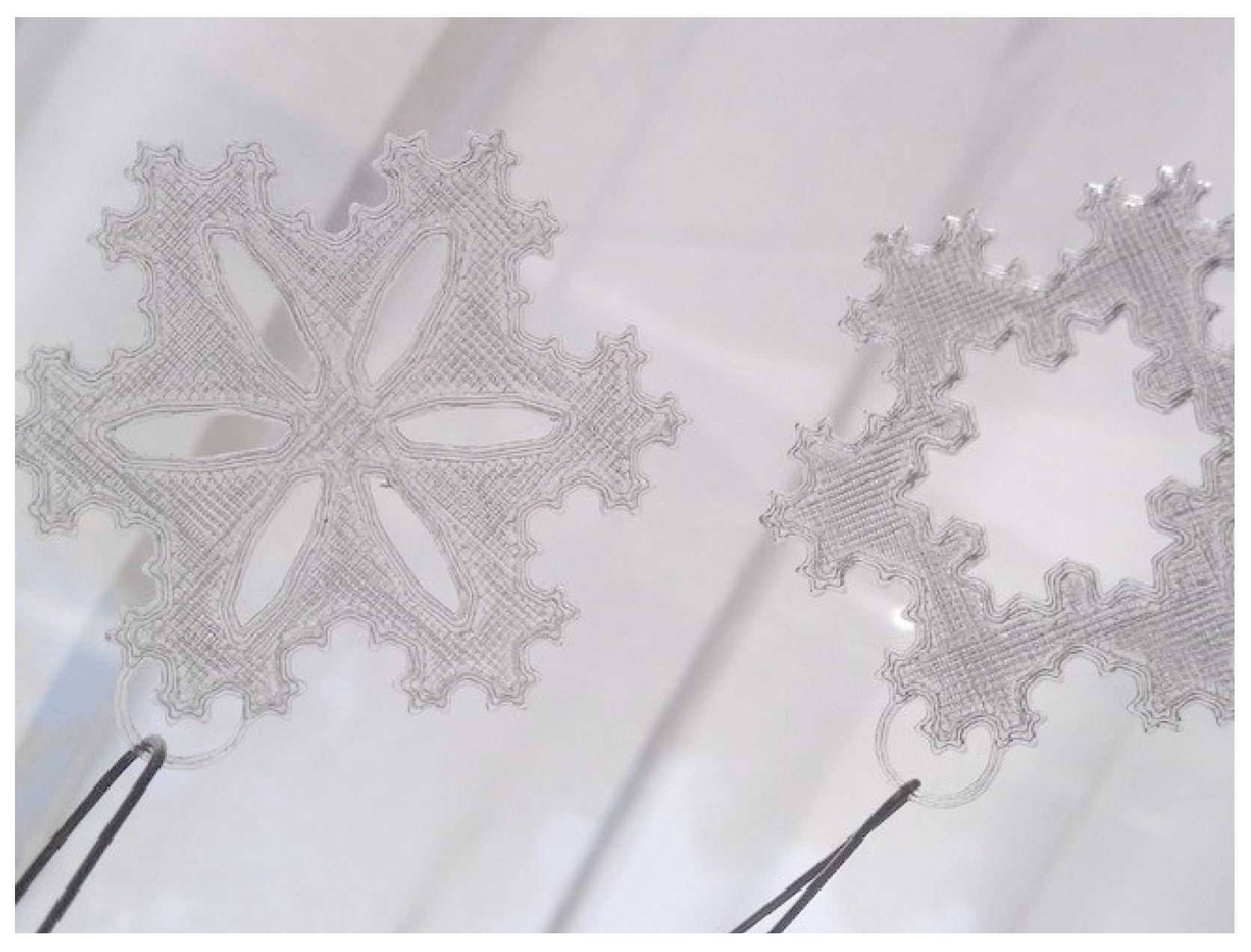
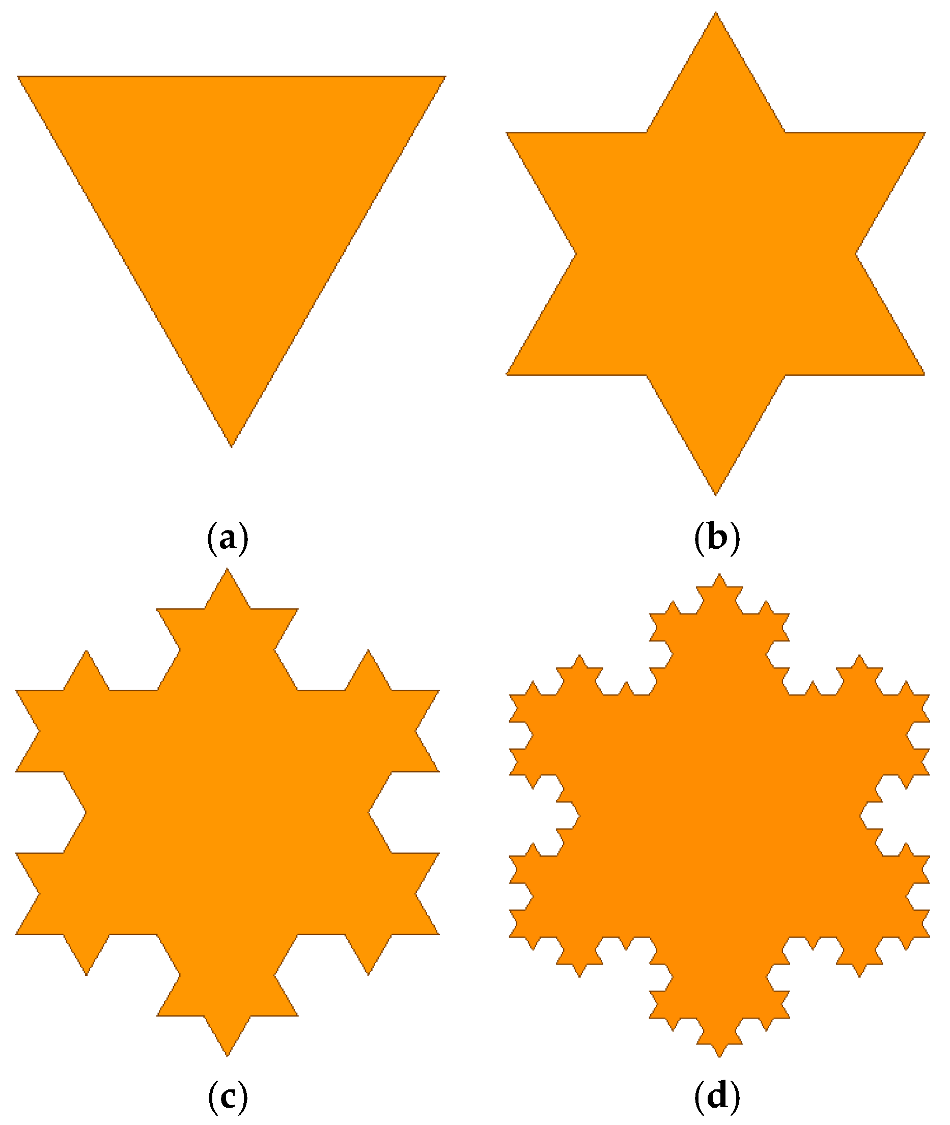
2.1. Koch Snowflake Fractal Theory
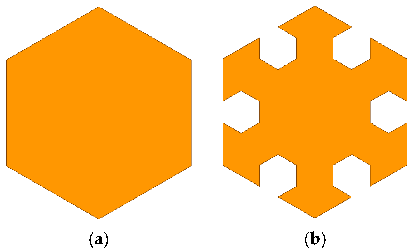
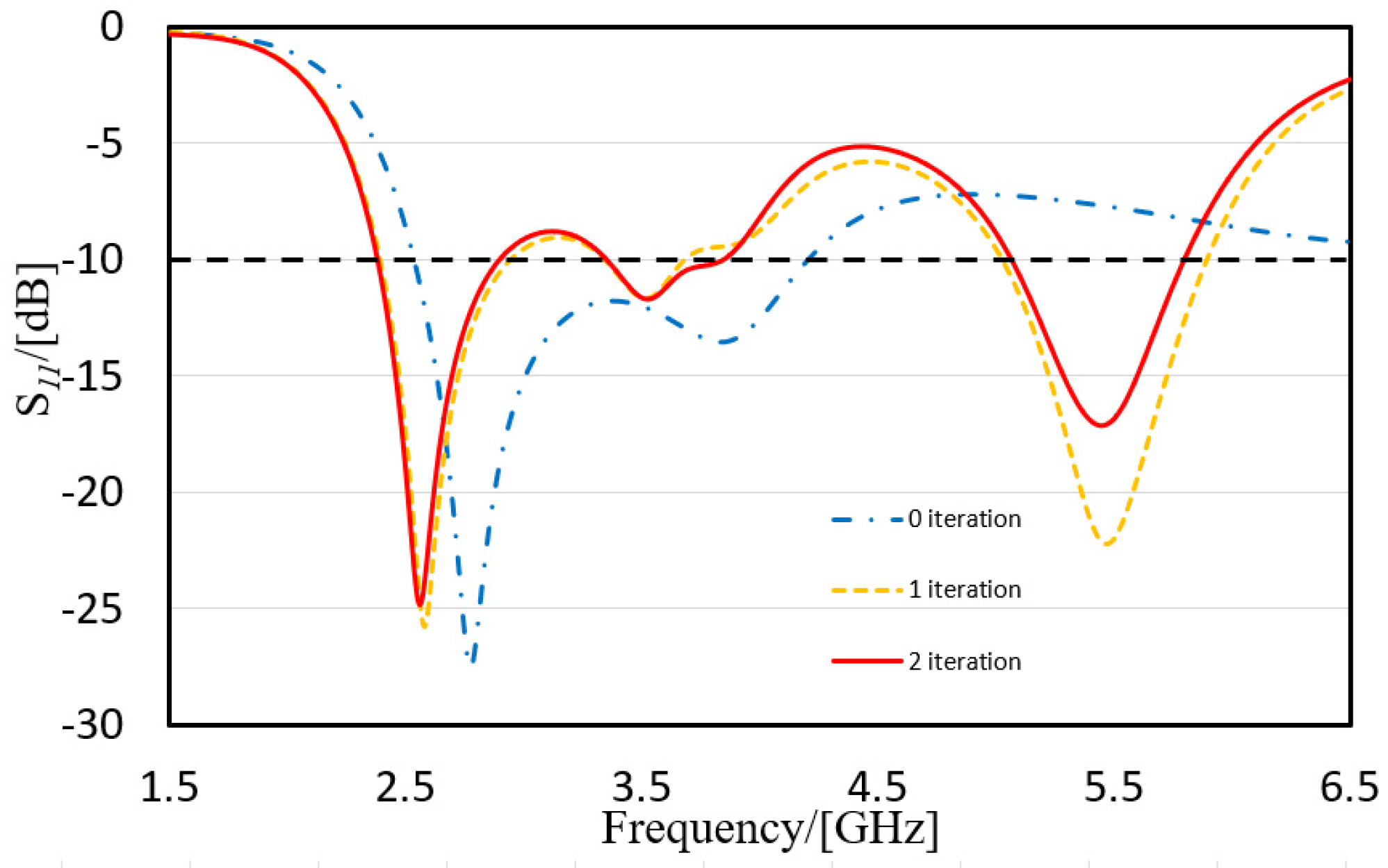
2.2. Hexagonal Fractal Iteration
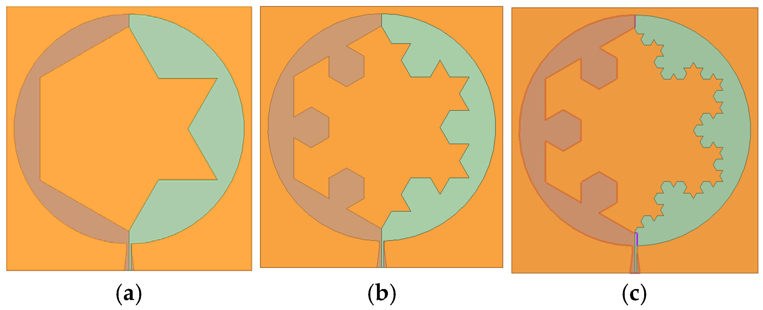
2.3. Characteristics of Antenna Structure
3. Results and Discussion
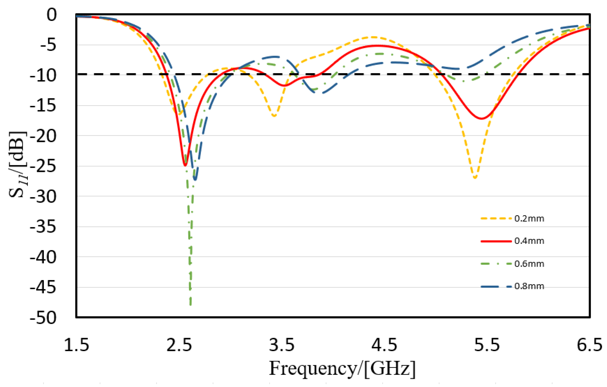
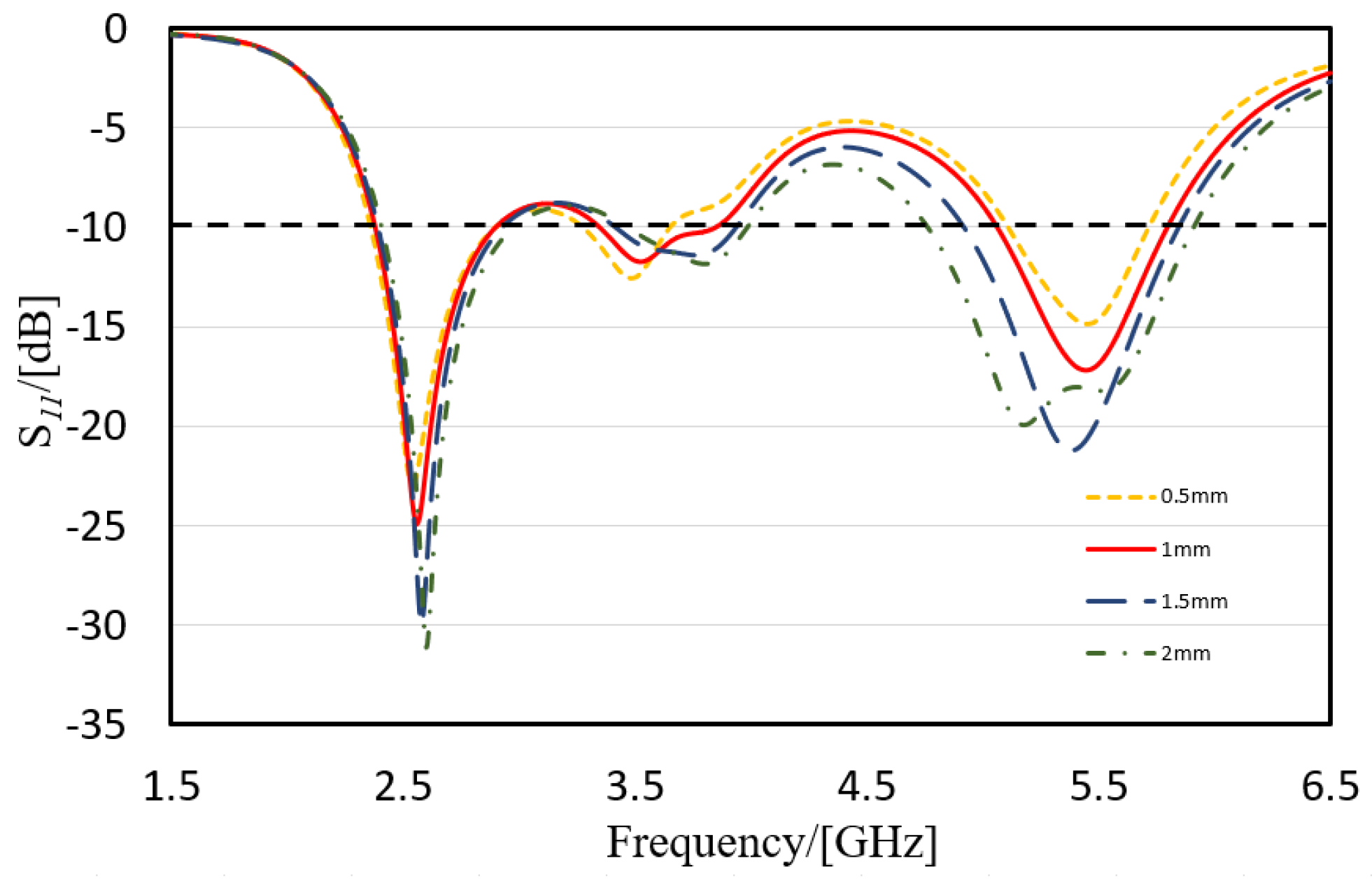
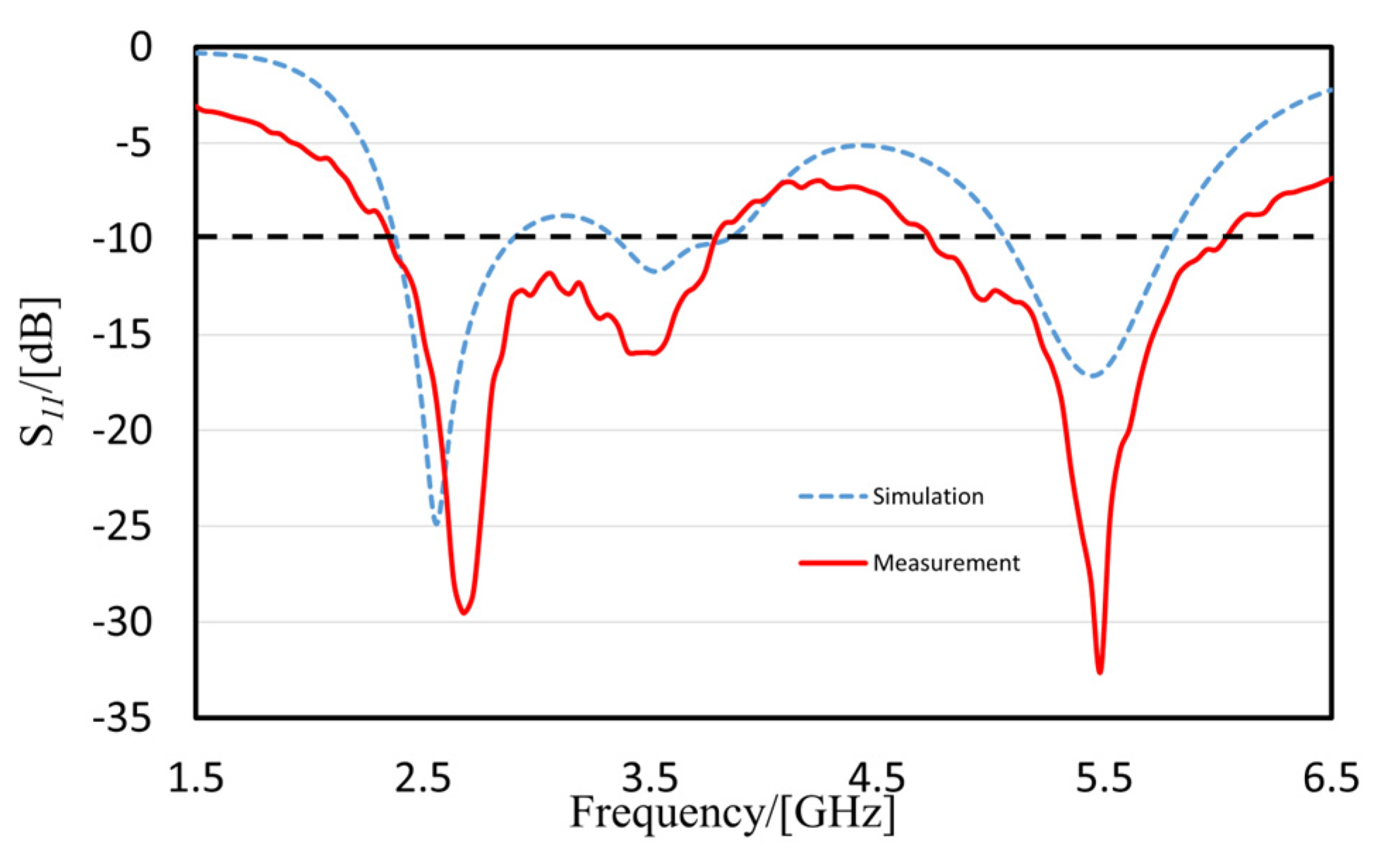
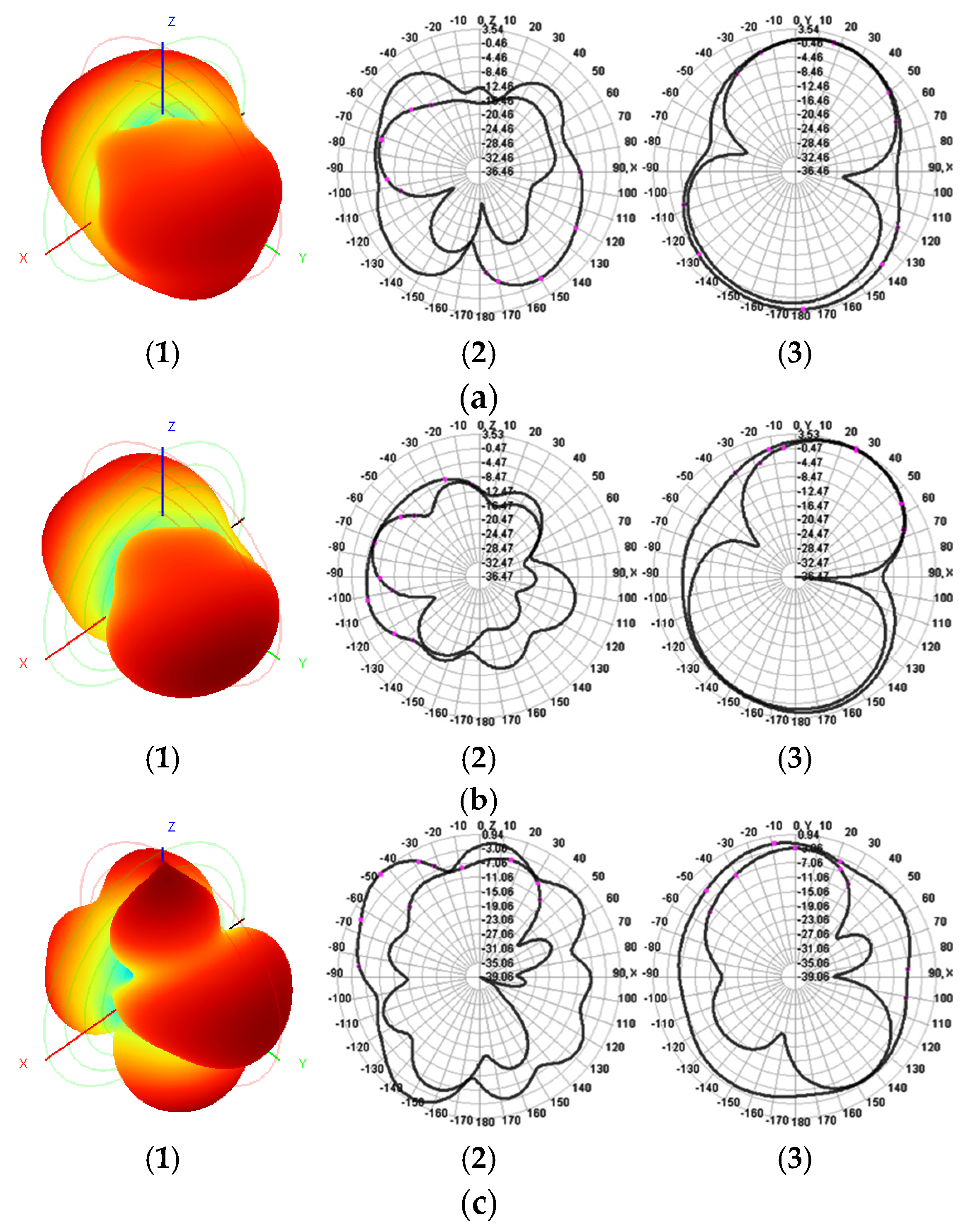
3.1. Simulation Results
3.2. The Simulation of a Reflector on the Back of an Antenna
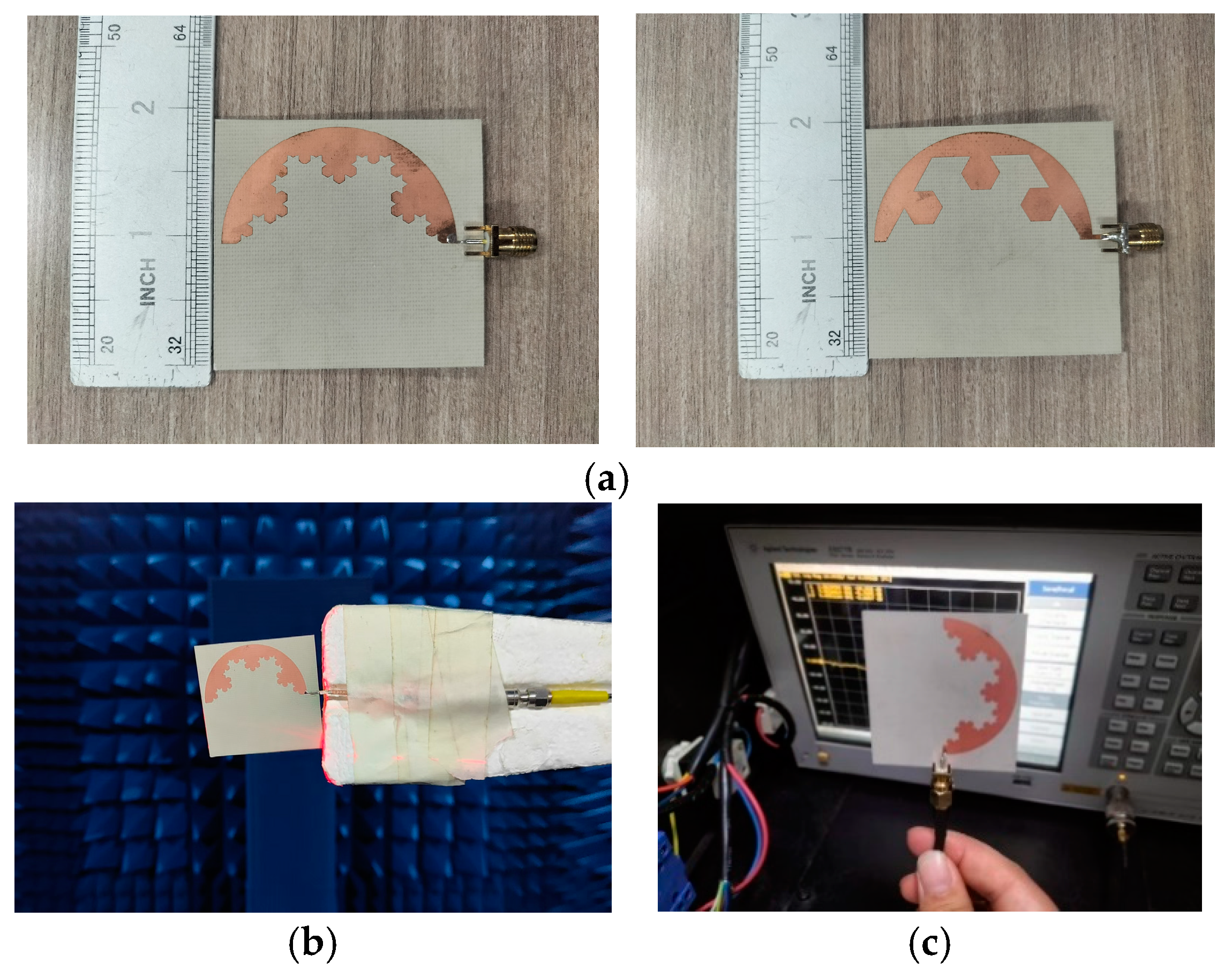
4. Fabrication and Measurement Results
4.1. Antenna Measurement
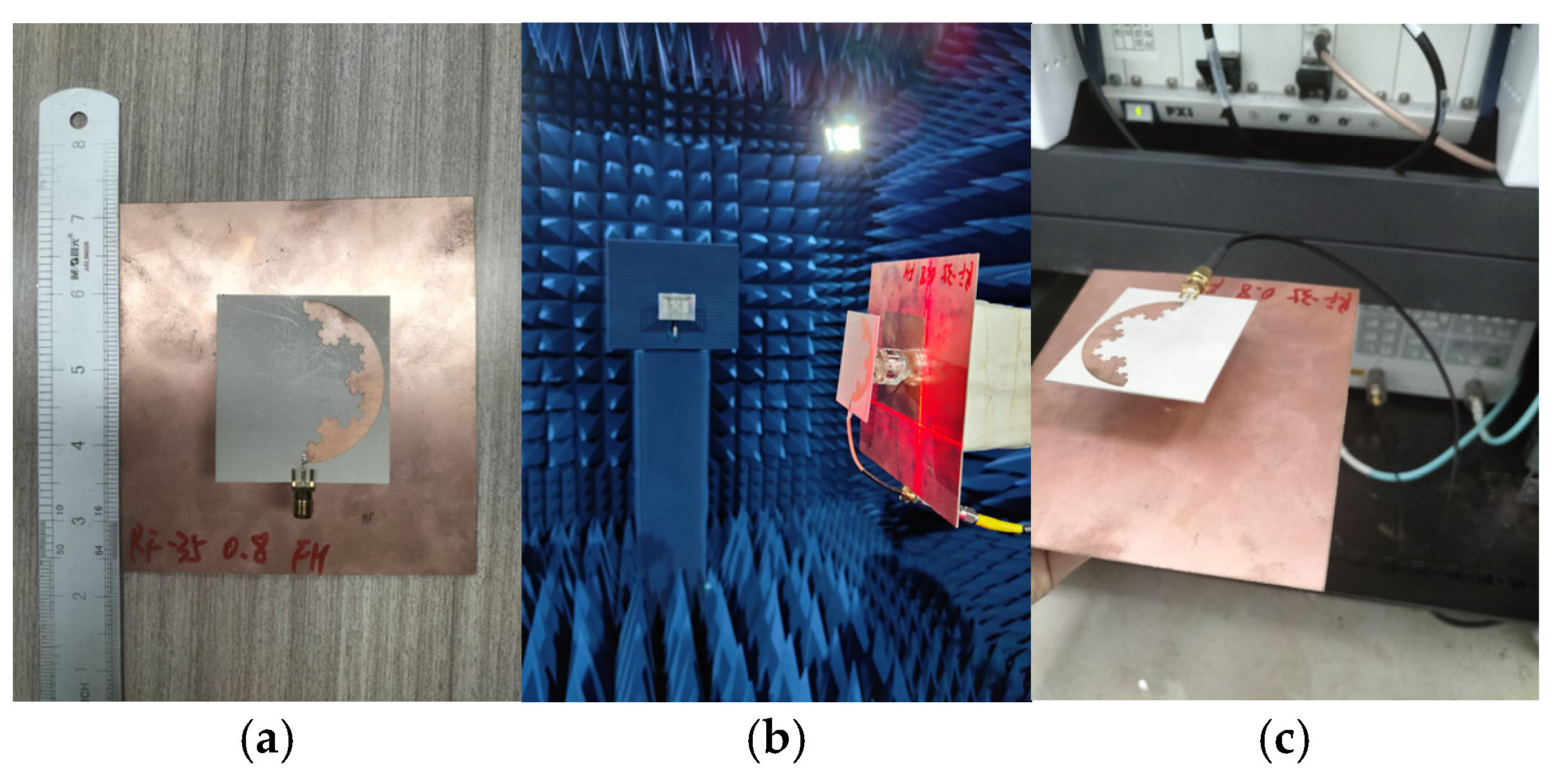
4.2. The Measurement of a Reflector on the Back of an Antenna
5. Discussion
Author Contributions
Funding
Data Availability Statement
Conflicts of Interest
References
- Patel, D.H.; Makwana, G.D. Multiband antenna for 2G/3G/4G and sub-6 GHz 5G applications using characteristic mode analysis. Prog. Electromagn. Res. M. 2023, 115, 107–117. [Google Scholar] [CrossRef]
- Mishra, P.; Kulat, K.D. Small-size multiband printed monopole antenna for wireless applications. Int. J. Microw. Wirel. Technol. 2023, 15, 1801–1808. [Google Scholar] [CrossRef]
- Huang, D.; Du, Z.; Wang, Y. An octa-band monopole antenna with a small nonground portion height for LTE/WLAN mobile phones. IEEE Trans. Antennas Propag. 2016, 70, 842–849. [Google Scholar] [CrossRef]
- Varghese, S.; Abdulla, P.; Baby, A.M.; Jasmine, P.M. High-Gain Dual-Band Waveguide-Fed Dielectric Resonator Antenna. IEEE Antennas Wirel. Propag. Lett. 2022, 21, 232–236. [Google Scholar] [CrossRef]
- Yu, Z.; Lin, Z.; Ran, X.; Li, Y.; Liang, B.; Wang, X. A Novel “hui” Pane Structure Multiband Microstrip Antenna for 2G/3G/4G/5G/WLAN/Navigation Applications. Int. J. Antennas Propag. 2021, 2021, 5567417. [Google Scholar] [CrossRef]
- Kamili, J.B.; Addepalli, T.; Perli, B.R.; Kumar, B.K.; Mohammed, Y.T. Design of a novel four-element Koch–Sierpinski fractal mmWave antenna for 5G applications. Int. J. Electron. 2023, 1–21. [Google Scholar] [CrossRef]
- Koohestani, M.; Golpour, M. U-shaped microstrip patch antenna with novel parasitic tuning stubs for ultra wideband applications. IET Microw. Antennas Propag. 2010, 4, 938–946. [Google Scholar] [CrossRef]
- Xiaoxing, Z.; Wangting, L.; Xiaohua, Y. Hilbert Fractal Antenna for Detecting GIS PD and Portable Monitoring System. J. Chongqing Univ. 2009, 32, 263–268. [Google Scholar]
- Li, Y.; Li, L.; Zhang, Y.; Zhao, C. Design and Synthesis of Multilayer Frequency Selective Surface Based on Antenna-Filter-Antenna Using Minkowski Fractal Structures. IEEE Trans. Antennas Propag. 2015, 63, 133–141. [Google Scholar] [CrossRef]
- Tripathi, S.; Mohan, A.; Yadav, S. A compact octagonal fractal UWB MIMO antenna with WLAN band rejection. Microw. Opt. Technol. Lett. 2015, 57, 1919–1925. [Google Scholar] [CrossRef]
- Shinde, P.N.; Shinde, J.P. Design of compact pentagonal slot antenna with bandwidth enhancement for multiband wireless applications. AEU Int. J. Electron. Commun. 2015, 69, 1489–1494. [Google Scholar]
- Chu, Q.-X.; Li, X.-R.; Ye, M. High-Gain Printed Log-Periodic Dipole Array Antenna with Parasitic Cell for 5G Communication. IEEE Trans. Antennas Propag. 2017, 65, 6338–6344. [Google Scholar] [CrossRef]
- Pandya, A.; Upadhyaya, T.K.; Pandya, K. Design of Metamaterial Based Multilayer Antenna for Navigation/Wifi/Satellite Applications. Prog. Electromagn. Res. M 2021, 99, 103–113. [Google Scholar] [CrossRef]
- Ji, L.-Y.; Guo, Y.J.; Qin, P.-Y.; Gong, S.-X.; Mittra, R. A Reconfigurable Partially Reflective Surface (PRS) Antenna for Beam Steering. IEEE Trans. Antennas Propag. 2015, 63, 2387–2395. [Google Scholar] [CrossRef]
- Qin, P.Y.; Ji, L.Y.; Chen, S.L.; Guo, Y.J. Dual-Polarized Wideband Fabry–Perot Antenna with Quad-Layer Partially Reflective Surface. IEEE Antennas Wirel. Propag. Lett. 2018, 17, 551–554. [Google Scholar] [CrossRef]
- Ji, L.-Y.; Qin, P.-Y.; Guo, Y.J.; Ding, C.; Fu, G.; Gong, S.-X. A Wideband Polarization Reconfigurable Antenna with Partially Reflective Surface. IEEE Trans. Antennas Propag. 2016, 64, 4534–4538. [Google Scholar] [CrossRef]
- Li, W.T.; Hei, Y.Q.; Grubb, P.M.; Shi, X.W.; Chen, R.T. Inkjet Printing of Wideband Stacked Microstrip Patch Array Antenna on Ultrathin Flexible Substrates. IEEE Trans. Compon. Packag. Manuf. Technol. 2018, 8, 1695–1701. [Google Scholar] [CrossRef]
- Chakraborty, M.; Chakraborty, S.; Reddy, P.S.; Samanta, S. High Performance DGS Integrated Compact Antenna for 2.4/5.2/5.8 GHz WLAN Band. Radioengineering 2017, 26, 71–77. [Google Scholar] [CrossRef]
- Hao, Z.-C.; Liu, X.; Huo, X.; Fan, K.-K. Planar high-gain circularly polarized element antenna for array applications. IEEE Trans. Antennas Propag. 2015, 63, 1937–1947. [Google Scholar] [CrossRef]
- Gorai, A.; Dasgupta, A.; Ghatak, R. A compact quasi-self-complementary dual band notched UWB MIMO antenna with enhanced isolation using Hilbert fractal slot. AEU Int. J. Electron. Commun. 2018, 94, 36–41. [Google Scholar] [CrossRef]
- Sood, M.; Rai, A. Wideband 4-port MIMO antenna array using fractal and complimentary split-ring structure for Ku-band appliances. AEU Int. J. Electron. Commun. 2023, 172, 154970. [Google Scholar] [CrossRef]
- Patel, U.; Upadhyaya, T.; Sorathiya, V.; Pandya, K.; Alwabli, A.; Dave, K.; Soliman, N.F.; El-Shafai, W. Split Ring Resonator Geometry Inspired Crossed Flower Shaped Fractal Antenna for Satellite and 5G Communication Applications. Results Eng. 2024, 22, 102110. [Google Scholar] [CrossRef]
- Paulkani, I.; Indumathi, G. A Low Profile Meta-Material Loaded Koch Fractal Antenna for Broadband Public Safety Applications. Wirel. Pers. Commun. 2023, 128, 813–827. [Google Scholar] [CrossRef]


| Dimensions Parameters | W | L | R | S | S1 | S2 | S3 | K | K1 |
| Unit (mm) | 50 | 54 | 47 | 1.3 | 4 | 12 | 36 | 8 | 0.4 |
| Dimensions Parameters | K2 | H | H1 | G | G1 | ||||
| Unit (mm) | 1 | 41.8 | 8.2 | 21 | 4.2 |
| Freq | Ang | Mag | RX | Z0 | Y |
|---|---|---|---|---|---|
| 2.56 | 147.66 | 0.047 | 0.923 + 0.046i | 46.14 + 2.31j | 0.022 − 0.001j |
| 3.54 | −117.23 | 0.191 | 0.795 − 0.281i | 39.77 − 14.03j | 0.022 + 0.008j |
| 5.45 | −82.21 | 0.282 | 0.918 − 0.557i | 45.89 − 27.83j | 0.016 + 0.010j |
| Band No. | Bandwidth (Simulation) | Covered Commercial Bands |
|---|---|---|
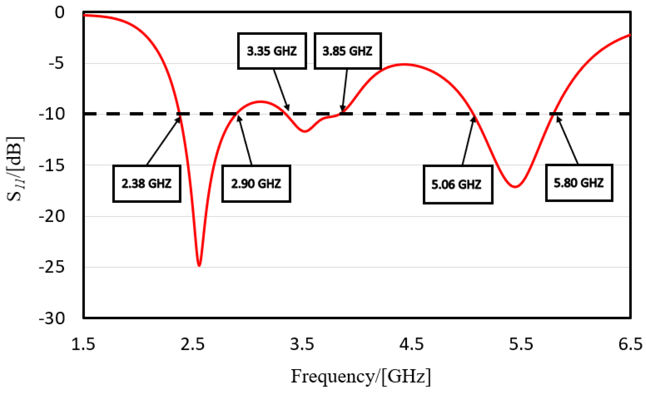
| 1 | 2.38–2.90 GHz (20.3%) | WLAN (802.11 b/g/n: 2400–2480 MHZ) Bluetooth (2400–2483.5 MHZ) BDS (2491.75 ± 4.08 MHZ) ISM2400(2.420–2.4835 GHz) WiMAX (2.3–2.7 GHz) TD-LTE (2300–2390 MHz, 2555–2655 MHz) |
| 2 | 3.35–3.85 GHz (14.1%) | WiMAX (3.3–3.8 GHz) LTE42/43 (3.4–3.8 GHz) 5G band n78 (3.4–3.8 GHz) |
| 3 | 5.06–5.80 GHz (13.5%) | WLAN (802.11 a/n:5.15–5.35 GHz) 5G (5.725–5.825 GHz) |
| Band No. | Bandwidth | Covered Commercial Bands |
|---|---|---|
| 1 | 2.33–3.78 GHz | WLAN (802.11 b/g/n: 2400–2480 MHZ) Bluetooth (2400–2483.5 MHZ) BD S(2491.75 MHZ ± 4.08 MHZ) ISM2400 (2.420–2.4835 GHz) WiMAX (2.3–2.7 GHz) TD-LTE (2300–2390 MHz, 2555–2655 MHz) LTE42/43 (3.4–3.8 GHz) WiMAX (3.3–3.8 GHz) 5G band n78 (3.4 GHz–3.8 GHz) |
| 2 | 4.75–5.99 GHz | WLAN (802.11 a/n:5.15–5.35 GHz) 5G (5.725–5.825 GHz) |
| Ref. | Size (mm2) | Centre Frequency (GHz) | Maximum Gain (dBi) | Substrate Material | Applications |
|---|---|---|---|---|---|
| [1] | 80 × 80 | 1.56/2.49/3.5/5.24 | 2.45 | Rogers AD255C | 2G/3G/4G |
| [5] | 85 × 70 | 1.6/2.35/3.8/5.85 | 4.99 | FR4 | 5G/WLAN/Navigation |
| [11] | 150 × 80 | 3.6 | 5.3 | FR4 | Sub-6 GHz band |
| [13] | 83 × 56 | 2.47/3.55/5.55 | 3.73 | FR4 | Navigation, WLAN |
| [18] | 35 × 27.4 | 5.2 | 4.14 | FR4 | WLAN band |
| [20] | 30 × 41 | 5.5/8.1 | 4 | FR4 | / |
| [21] | 58.45 × 58.45 | 14.6 | 3.81 | FR4 | Ku-band |
| [22] | 74 × 70 | 4.5/7.7 | 2.05 | FR4 | 5G Sub-6 GHz |
| [23] | 26 × 26 | 4.89 | 1.56 | FR4 | Public Protection |
| Prop | 50 × 54 | 2.5/3.5/5.5 | 4.7 | Taconic RF-35(tm) | 4G/5G/WLAN/Navigation |
Disclaimer/Publisher’s Note: The statements, opinions and data contained in all publications are solely those of the individual author(s) and contributor(s) and not of MDPI and/or the editor(s). MDPI and/or the editor(s) disclaim responsibility for any injury to people or property resulting from any ideas, methods, instructions or products referred to in the content. |
© 2025 by the authors. Licensee MDPI, Basel, Switzerland. This article is an open access article distributed under the terms and conditions of the Creative Commons Attribution (CC BY) license (https://creativecommons.org/licenses/by/4.0/).
Share and Cite
Yu, Z.; Chang, Y.; Niu, R.; Zhang, R.; Wang, F.; Sun, R.; Zhang, G.; Ran, X. A New Koch and Hexagonal Fractal Combined Circular Structure Antenna for 4G/5G/WLAN Applications. Electronics 2025, 14, 237. https://doi.org/10.3390/electronics14020237
Yu Z, Chang Y, Niu R, Zhang R, Wang F, Sun R, Zhang G, Ran X. A New Koch and Hexagonal Fractal Combined Circular Structure Antenna for 4G/5G/WLAN Applications. Electronics. 2025; 14(2):237. https://doi.org/10.3390/electronics14020237
Chicago/Turabian StyleYu, Zhen, Yi Chang, Ruirong Niu, Ruixin Zhang, Feng Wang, Runzhi Sun, Guodong Zhang, and Xiaoying Ran. 2025. "A New Koch and Hexagonal Fractal Combined Circular Structure Antenna for 4G/5G/WLAN Applications" Electronics 14, no. 2: 237. https://doi.org/10.3390/electronics14020237
APA StyleYu, Z., Chang, Y., Niu, R., Zhang, R., Wang, F., Sun, R., Zhang, G., & Ran, X. (2025). A New Koch and Hexagonal Fractal Combined Circular Structure Antenna for 4G/5G/WLAN Applications. Electronics, 14(2), 237. https://doi.org/10.3390/electronics14020237