Article

Compact Tri-Band Bandpass Filter with Wide Upper Stopband Based on Spoof Surface Plasmon Polaritons and Open-/Short-Circuited Stubs

1
School of Information and Software Engineering, East China Jiaotong University, Nanchang 330013, China
2
State Key Laboratory of Millimeter Wave, Southeast University, Nanjing 210096, China
3
School of Information and Communications Engineering, Xi’an Jiaotong University, Xi’an 710049, China
*
Authors to whom correspondence should be addressed.
Electronics 2025, 14(2), 285; https://doi.org/10.3390/electronics14020285
Submission received: 21 December 2024 / Revised: 8 January 2025 / Accepted: 10 January 2025 / Published: 12 January 2025
(This article belongs to the Section Microwave and Wireless Communications)

Abstract

:
In this paper, a new U-shaped ring spoof surface plasmon polariton (SSPP) structure is proposed as part of a bandpass filter (BPF) combined with short-circuited stubs (SCSs). The U-shaped ring unit offers miniaturization and multiple adjustable parameters. Furthermore, the lower and upper cutoff frequencies of the passband for the BPF can be adjusted by modifying the structural parameters of the SSPP units and SCSs, respectively. To validate the design, a prototype filter was first created with a frequency range of 2 to 3.7 GHz for the passband and an extended stopband that reached up to 15 GHz. On the basis of the designed BPF, a tri-band filter was realized by introducing multiple transmission zeros by loading multiple open-circuited stubs (OCSs) onto the transmission portion of SSPPs. The center frequencies of the three passbands were 1.20 GHz, 2.03 GHz, and 2.96 GHz, respectively. At the same time, the upper stopband rejection reached up to 12 GHz with an attenuation of −30 dB, about 10 times the center frequency of the first passband. The experimental results demonstrate a strong correlation between the measured and simulated outcomes, thereby validating the proposed structure and design methodology. Notably, the filter measures only 0.38λg × 0.13λg, highlighting its compact size as a significant advantage.

1. Introduction

With the rapid advancement of fifth-generation (5G) communication systems, microwave frequency resources have become increasingly limited. Enhancing spectrum utilization and mitigating external signal interference have emerged as critical issues that require urgent attention. To solve the above problems, multi-band bandpass filters (BPFs) are widely used. On the other hand, surface plasmon polaritons (SPPs) are a type of surface waves that propagate along the interface between a metal and a dielectric material [1]. Due to their remarkable ability to confine electromagnetic fields, SPPs have been extensively researched and utilized in the optical frequency range [2,3,4]. To expand the utility of these surface waves into the terahertz and microwave regions, spoof surface plasmon polaritons (SSPPs) with surface modes similar to those of SPPs have been proposed for the first time [5]. SSPPs are constructed by adding periodic patterns to the conductor, and the desired properties can be achieved by varying the geometry of the periodic structure [6,7]. SSPPs are characterized by high transmission efficiency [8] and strong field constraint [9], and are widely used in the fields of filters [10,11], power dividers [12], diplexers [13], antennas [14,15], etc.
In the past few years, some research on SSPP-based multi-band filters has been reported [16,17,18]. In [16], a tri-band BPF utilizing multi-mode SSPP cells for microwave frequencies is proposed. However, its loss within the passband is relatively high, which is not conducive to the transmission of communication signals. In [17], the bandpass response is obtained by combining substrate integrated waveguide (SIW) with SSPPs, and then two transmission zeros are generated in the passband by etching the C-ring resonator to obtain the response of the three passbands. However, the circuit size is relatively large, and this design does not consider the characteristics of out-of-band suppression. In [18], by using the high-order modes of the asymmetric folded line SSPP unit, the tri-band frequency response is obtained, but their passband frequencies are affected by the high-order modes and are difficult to be regulated freely. In addition, it also does not consider out-of-band suppression. So, multi-band filters based on SSPP structures, with desirable performance in both the passband and stopband, need to be further researched.
In this paper, we initially design a wide-stopband BPF utilizing U-shaped ring SSPPs and SCSs. The bandpass response is achieved by combining the low-pass characteristics of the SSPP structure with the high-pass characteristics of the SCSs. On this basis, by loading multiple open-circuited stubs (OCSs), multiple transmission zeros are generated in the passband and the tri-band frequency response is obtained. Moreover, the bandwidths of three passbands can be flexibly controlled and a wide stopband performance of up to 10 times the first passband frequency is also realized. Finally, a tri-band filter operating at 1.20 GHz, 2.03 GHz, and 2.96 GHz is designed, fabricated, and measured. Due to the use of the fundamental mode of SSPPs and U-shaped ring unit structure, the miniaturization of the filter is realized, and the final circuit size is only 0.38λg × 0.13λg.

2. Analysis of New SSPP Unit

The configurations of the traditional rectangular SSPP unit (Type A) and the ring-shaped SSPP unit (Type B), and the U-shaped ring SSPP unit (Type C) proposed in this paper are shown in Figure 1a–c, respectively, where the yellow portion is the metallic copper, and the blue portion is the substrate. The substrate employed in this study is Rogers RT5880, characterized by a dielectric constant of 2.2 relative to air and a thickness of 0.508 mm. The physical parameters depicted in Figure 1 are all defined in detail as p = 7, w1 = 0.5, w2 = 0.5, w3 = 1.5, h = 8, d = 3, and s = 5.5 (unit: mm).
Among other things, it should be declared that the Type B structure [19] is a previously published structure by the authors, which, with the advantage of miniaturization, has been applied to the design of wide-stopband filters. However, this structure also has two shortcomings: firstly, the miniaturization performance is not outstanding enough, and secondly, the control of the cutoff frequency by the cell structure can only be controlled by the height h, which lacks the freedom of regulation. Therefore, in order to improve the above two deficiencies, the U-shaped ring unit structure of this paper is proposed. The U-shaped ring unit structure is obtained by bending and extending the upper edge of the ring downward on the basis of the ring unit structure, and the final unit structure is shown in Figure 1c.
To verify the advantages of the proposed U-shaped ring cell structure, the dispersion curves of three SSPP cell structures are given in Figure 2. The light line in Figure 2 serves to separate the fast-wave region from the slow-wave region, with the fast-wave region above the light line and the slow-wave region below the light line. It is common to design filters using SSPP units to take advantage of their slow-wave properties, which can be very good at binding the energy in the structure to subsequently reduce the filter loss. Furthermore, at the same period p and height h, the asymptotic frequency of Type B in mode 0 is only a little lower than that of Type A, which indicates that the miniaturization performance of Type B is not outstanding enough; meanwhile, the asymptotic frequency of Type C in mode 0 is much lower than that of Type A, which indicates that the miniaturization performance of Type C is greatly improved compared with that of Type B. The asymptotic frequency of the SSPP unit is represented as the upper cutoff frequency in the filter design. Therefore, the cutoff frequency of the filter can be adjusted by changing the asymptotic frequency to obtain the desired frequency range (e.g., 5G band).
In order to better investigate the frequency controllability of the proposed U-shaped ring SSPP structure, the variation in the dispersion curves with different parameters h and s is shown in Figure 3. For parameter h, let it increase from 7 mm to 9 mm; it can be found that the asymptotic frequency gradually moves to the low frequency. Similarly, as the parameter s increases from 4.5 mm to 6.5 mm, the asymptotic frequency also moves to the low frequency. Thus, compared with Type A and Type B, Type C has one more parameter to control the asymptotic frequency, which greatly improves the flexibility and controllability of the SSPP-based filter design.

3. Design of Wide-Stopband Tri-Band BPF

3.1. Wide-Stopband Bandpass Filter

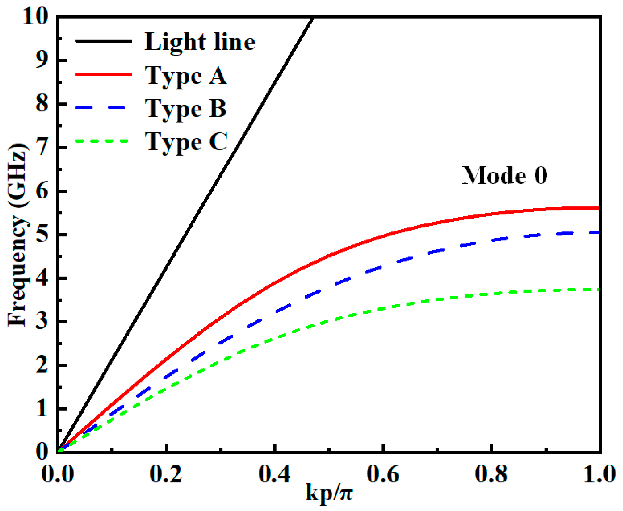
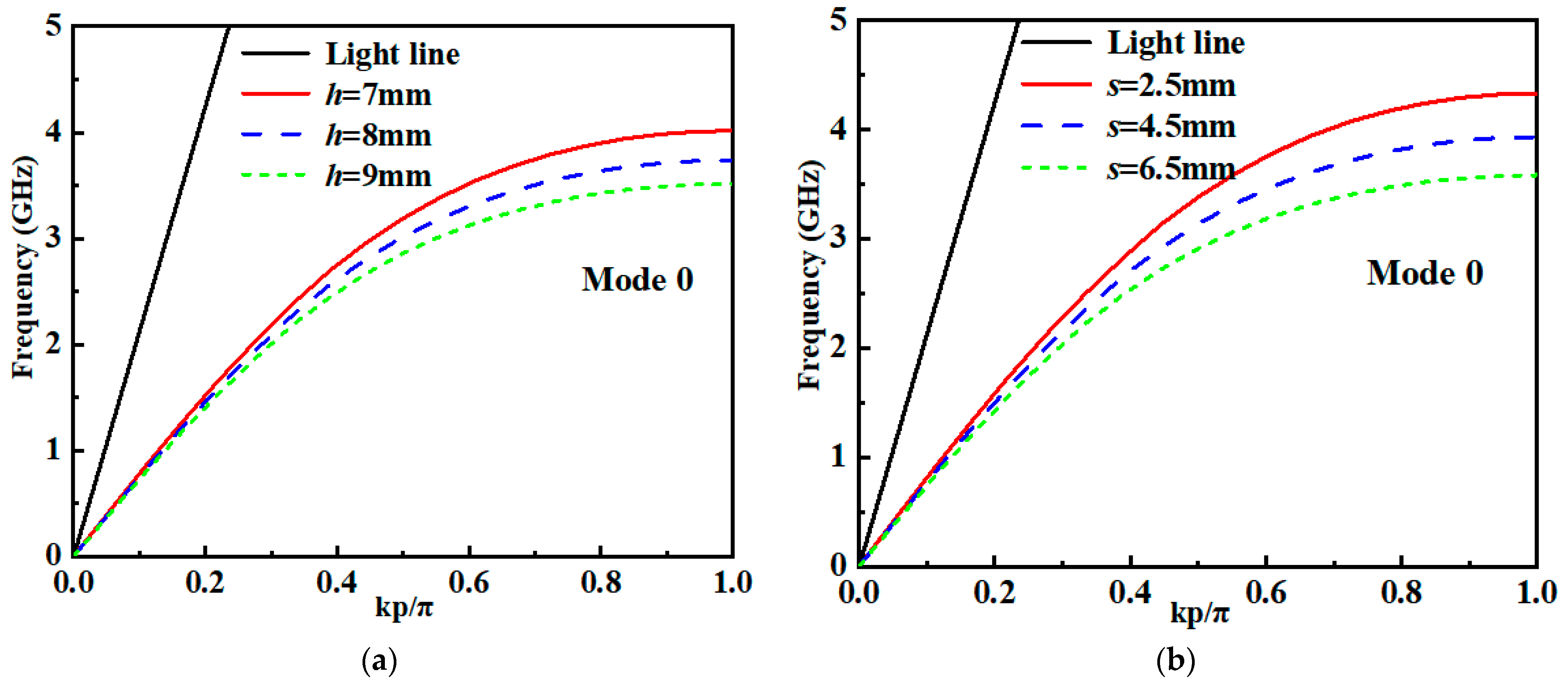
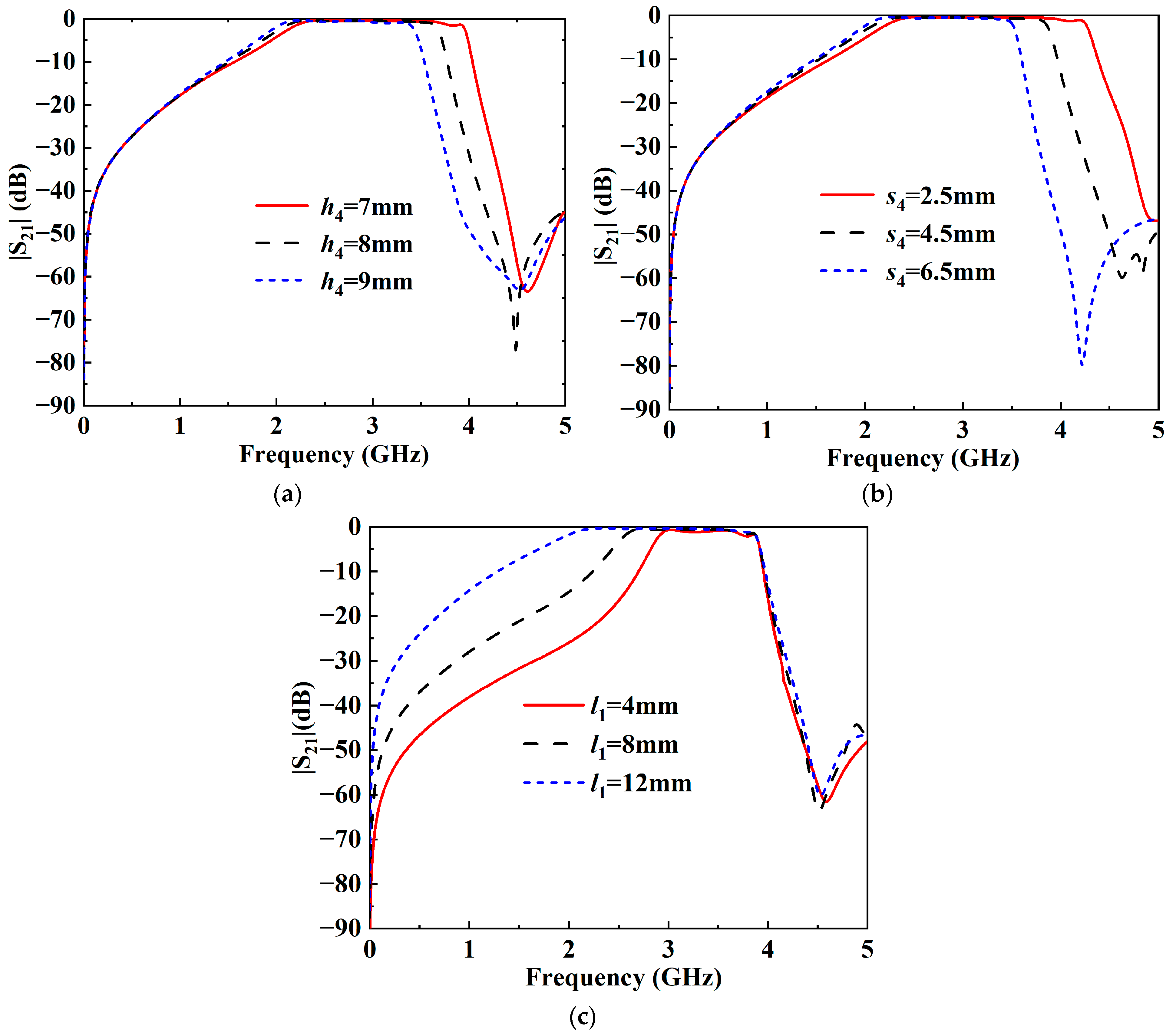
  • The upper and lower cutoff frequencies are the key points of the SSPP-based bandpass filter. The upper cutoff frequency of the bandpass filter is determined by the height (h) and depth of the slots (s) and the period (p) of the U-shaped ring SSPP cell. Generally, the period (p) is determined first, and then the height (h) of the U-shaped ring SSPP cell and the depth (s) of the slot are ascertained with the help of the dispersion curves. On the other hand, the lower cutoff frequency of the bandpass filter is controlled by the SCSs, mainly by using its resonance at 1/4λ, which produces similar high-pass characteristics. So, the lower cutoff frequency of the bandpass filter can be adjusted by changing the length of the SCSs.
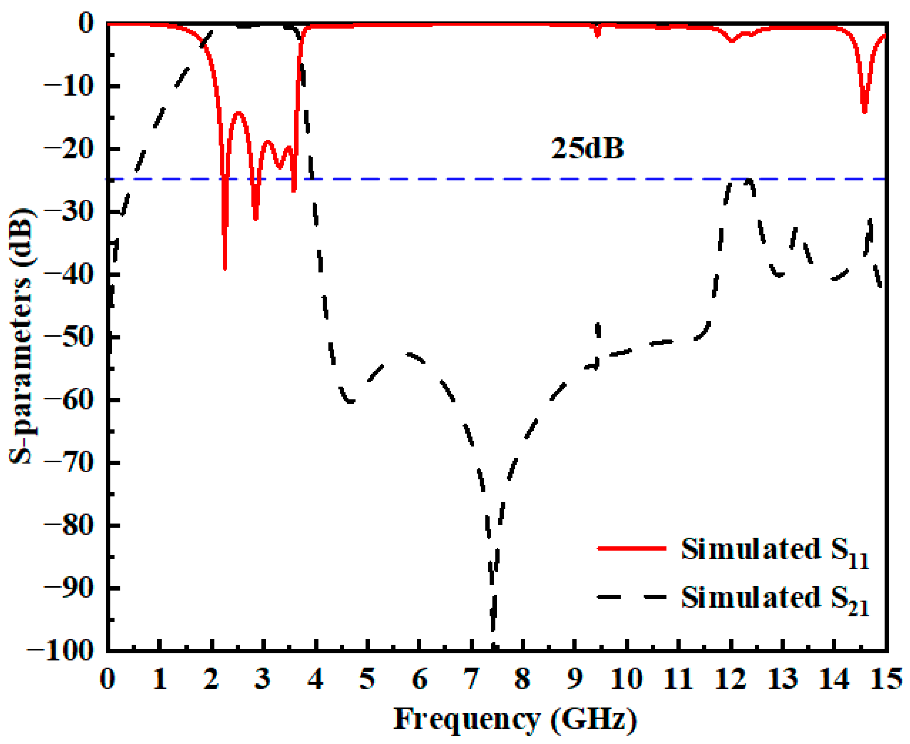
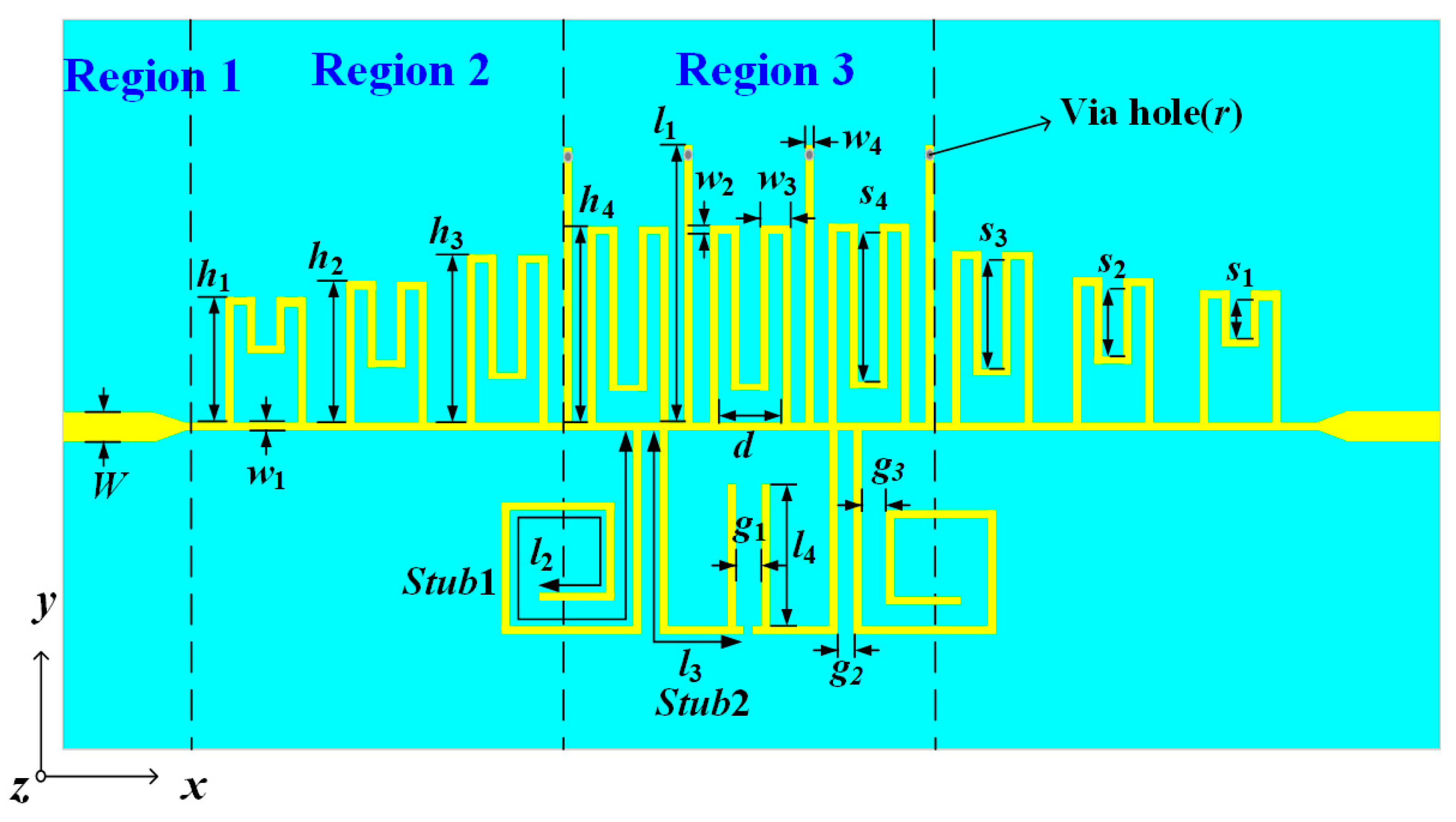
  • Utilizing the proposed U-shaped ring SSPP units and the SSPPs-SCSs integrated configuration, a BPF featuring a wide stopband has been designed for demonstration purposes. Figure 4 illustrates the schematic diagram of this BPF. This design includes the following components:
  • Region 1 consists of a microstrip line feeding section with a characteristic impedance of 50 Ω.
  • Region 2 includes a transition section with gradient-height U-shaped ring SSPP units.
  • Region 3 is made up of a transmission section that employs an SSPPs-SCSs integrated configuration. Four SCSs were placed equally spaced in the middle of the SSPP unit. Because the SCSs are placed between the SSPP cells, the size of the whole filter structure does not increase much.
Figure 4. Schematic of the designed BPF structure using U-shaped ring SSPPs and SCSs.
Electronics 14 00285 g004
We know that the height of the transition unit shows a gradient change, which can bring its cutoff frequency closer to that of the transmission unit, thereby achieving momentum and impedance matching. This process, however, will require a lot of transition units to achieve such a match. However, in this paper, the U-shaped ring unit structure can not only adjust the height h to control the asymptotic frequency, but also adjust the parameter s to control the asymptotic frequency, which implies that there is more than one parameter that can achieve this gradient change in the transition unit. This means that after ensuring the gradient change in the height of the transition unit, the gradient change in the parameter s can be controlled at the same time, which can achieve a wide range of asymptotic frequency change, and this process can achieve a better momentum and impedance matching, and avoid the problem of increasing the size due to the use of a larger number of transition units.
To assess the controllability of the designed filter band, three critical physical parameters were examined, as illustrated in Figure 5. In Figure 5a, as the height h4 of the SSPP cell increases from 7 mm to 9 mm, the upper cutoff frequency shifts toward higher frequencies, while the lower cutoff frequency remains largely unaffected, and the passband performance is consistent. Figure 5b shows that as the groove depth s of the SSPP cell increases from 2.5 mm to 6.5 mm, the upper cutoff frequency also shifts toward higher frequencies, with the lower cutoff frequency remaining relatively stable. Therefore, when the parameters h4 and s4 are changed at the same time, the upper cutoff frequency will change considerably, resulting in a wider frequency adjustment range. As depicted in Figure 5c, extending the length l of the SCSs from 4 mm to 12 mm causes the lower cutoff frequency to shift toward lower frequencies, with minimal impact on the upper cutoff frequency. Other parameters, such as the width of the SSPP cells (w2) and the width of the short-circuited stubs (w4), are also found to have a small effect on filter. So, they are not analyzed in detail here. This detailed analysis provides insights into how adjusting these parameters influences the filter’s performance characteristics. In addition, through the above analysis, it can be seen that the new structure proposed in this paper has multiple parameters to control the upper cutoff frequency, thereby improving the flexibility and controllability of the design.
It is worth noting that here we follow the method of loading SCSs and constructing bandpass filters as in Ref. [19]. There are two main advantages to loading SCSs. Firstly, the SIW structure requires the introduction of a large number of blind holes, and the spacing of these holes is small, which increases the difficulty of fabrication and introduces machining errors, whereas the SCS structure used in this paper requires the introduction of only four blind holes, and the spacing of the blind holes is large, significantly reducing fabrication difficulty and machining errors. Secondly, the SCSs are loaded between the SSPP cells and the final result is slightly smaller in size.
Figure 6 illustrates the simulated S-parameters of the designed wide-stopband BPF. It is clear that the filter achieves a desirable passband with an in-band return loss exceeding 15 dB. Additionally, it provides a wide stopband featuring more than 25 dB rejection from 3.9 GHz to 15 GHz. The final optimized values of all parameters of the BPF are summarized in Table 1.

3.2. Wide-Stopband Tri-Band Bandpass Filter

To meet the increased requirement of the multi-functional RF front end, a tri-band BPF is further designed on the basis of the previously designed BPF. Figure 7 shows the schematic diagram of the designed tri-band BPF. Compared with the BPF depicted in Figure 4, four more OCSs are introduced. The role of the OCSs is to generate a resonance, and the resonant frequency is determined by controlling the length of the stub. Therefore, multiple OCSs with different lengths can generate different resonances. In addition, the coupling of two adjacent OCSs will also generate transmission zeros, and the strength can be adjusted by coupling gap g. This is because, through the introduction of OCSs, multiple transmission zeros are introduced in the passband to achieve multiple passband transmissions. Also, the OCSs are bent for compactness. Though the introduction of the OCSs has an impact on impedance matching, the passband performance can be optimized by modulating the relevant parameters of the U-shaped unit in the transition section (region 2). To enhance momentum and achieve optimal impedance matching, the dimensions of the transition unit have been meticulously optimized. The final optimized values of all parameters of the tri-band BPF are summarized in Table 2.
Figure 8 illustrates the impact of various parameters of the OCSs on the transmission zeros. From Figure 8a, it is evident that as the length of l2 increases, the transmission zeros (TZ1) and (TZ2) shift to lower frequencies, with no significant effect on (TZ3) and (TZ4). Notably, the proximity of (TZ1) and (TZ2) results in a stopband suppression of 60 dB between the first and second passbands. In Figure 8b, the increase in the length of l3 causes TZ3 and TZ4 to move to lower frequencies, without affecting TZ1 and TZ2. Figure 8c demonstrates that as the parameter g1 increases, TZ3 and TZ4 become closer, enhancing the stopband suppression between the second and third passbands. It can be concluded from the above analysis that controlling the parameters related to the OCSs achieves effective control of the transmission zeros. Thus, the bandwidths of three passbands can be adjusted freely.

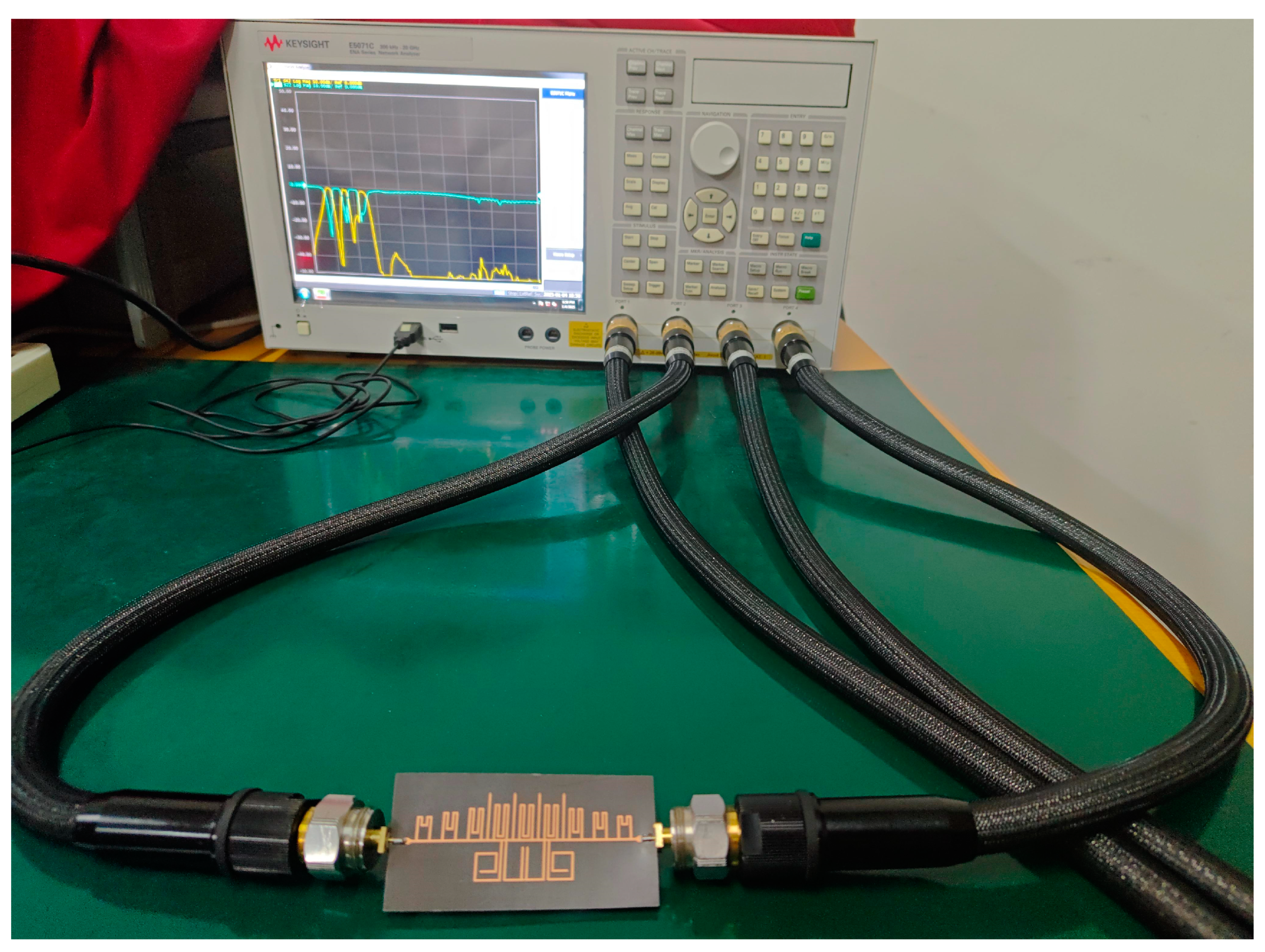
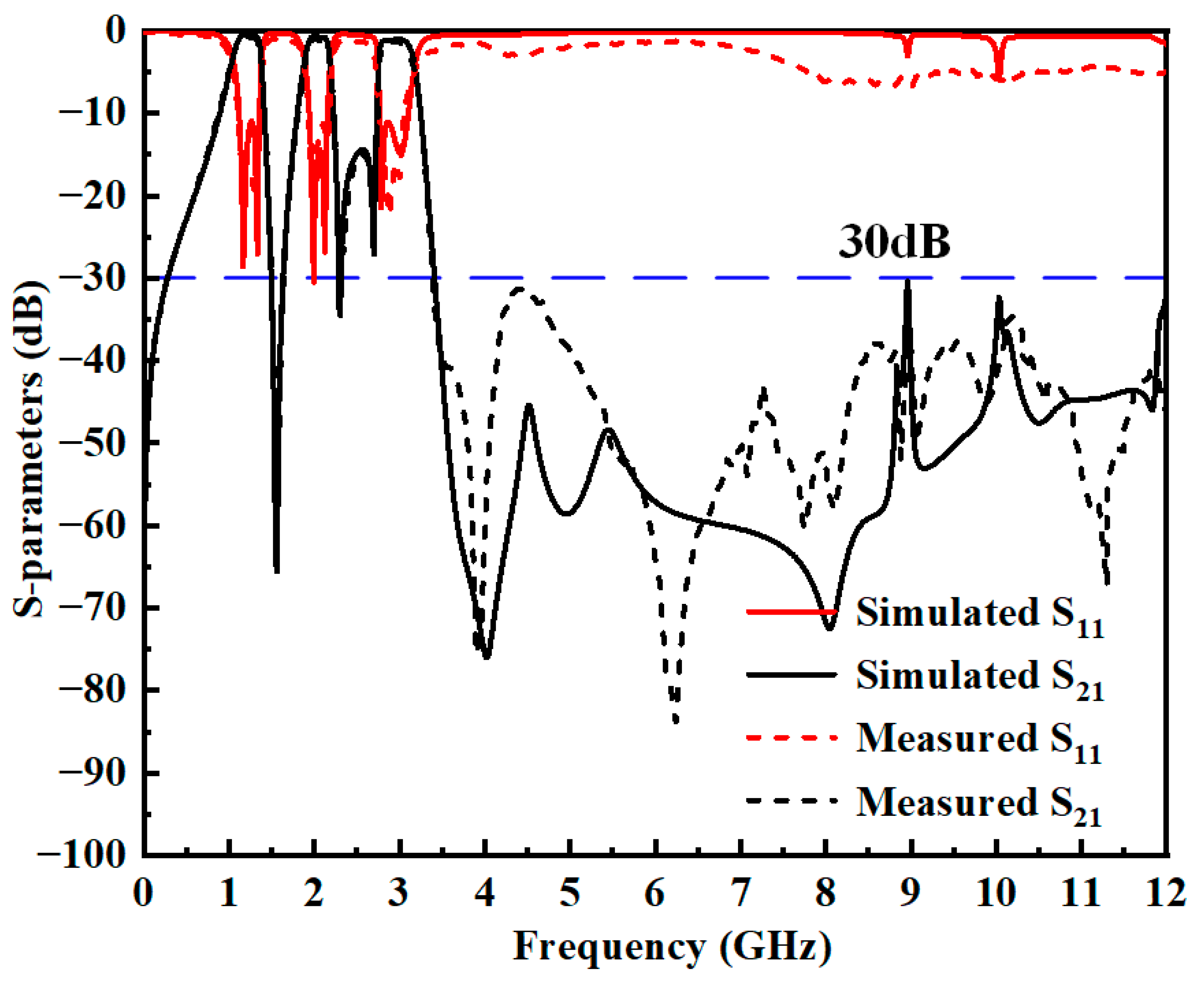
4. Experimental Validation

For illustrative purposes, the aforementioned meticulously designed tri-band BPF was fabricated using Rogers RT5880 substrate material, as depicted in Figure 9. The size was only 0.38λg × 0.13λg. The fabricated tri-band BPF was measured through a four-port test system, as shown in Figure 10. The fabricated tri-band BPF was placed on a table and connected to the Keysight E5071C network analyzer via two 3.5 mm connectors and two 3.5 mm coaxial cables. The two ports were calibrated in sequence using a short, open, load, and pass-through standard to mitigate the effects of the connectors and cables. Subsequently, the S-parameters of the BPF can be measured. The final simulated results after optimization for the designed tri-band filter are shown as solid lines in Figure 11. The measured results are represented by the dashed lines in the same figure. The measured center frequencies of the three passbands were 1.20 GHz, 2.03 GHz, and 2.96 GHz, respectively. The measured in-band insertion losses (ILs) for the three passbands were 0.56 dB, 1.1 dB, and 1.2 dB, respectively. The upper stopband extended to 12 GHz, with an attenuation exceeding 30 dB. It is evident that the measured results align well with the simulations, although minor discrepancies can primarily be attributed to fabrication and measurement tolerances.
To more clearly demonstrate the effectiveness of the proposed tri-band BPF within its operational frequency range and its performance outside the stopband, the simulated electric field distributions of the filter at 1.20 GHz, 2.03 GHz, 2.96 GHz (which are within the passband), and 12 GHz (which is within the stopband) are illustrated in Figure 12. The results indicate that at 1.20 GHz, 2.03 GHz, and 2.96 GHz, the electromagnetic waves can propagate from the input port to the output port with minimal attenuation. In contrast, at 12 GHz, the field rapidly decays, confirming that the designed filter operates efficiently within the desired band and effectively blocks signals in the stopband. Furthermore, when compared to the prior related work listed in Table 3, we observe that the proposed tri-band BPF offers notable advantages in terms of circuit size, upper stopband suppression, and controlled bandwidths.

5. Conclusions

This paper presents the design of a compact tri-band BPF with a wide stopband, which utilizes the proposed structure of U-shaped ring SSPPs combined with open-/short-circuited stubs. The introduction of multiple open-circuited stubs produces multiple transmission zeros, thus realizing a response with three different passbands. The position of the transmission zero is effectively controlled by controlling the parameters associated with the open stub. The measured results demonstrate that the stopband is exceptionally wide, extending up to 12 GHz with an attenuation exceeding 30 dB. This bandwidth is approximately ten times the center frequency of the first passband. Furthermore, the designed filter boasts a compact circuit size. Additionally, the bandwidths of the three passbands can be adjusted with flexibility. These characteristics indicate that the proposed design has great potential for applications in the GPS, WIFI, and 5G communication system, offering excellent suppression across a broad spectrum.

Author Contributions

Conceptualization, B.R., W.C., and K.-D.X.; methodology, W.C.; formal analysis, W.C.; writing—original draft preparation, W.C.; writing—review and editing, B.R., X.Z., X.G., and K.-D.X.; supervision, B.R.; funding acquisition, B.R. All authors have read and agreed to the published version of the manuscript.

Funding

This research was supported in part by the National Natural Science Foundation of China under Grant 62261022, 62361025, 62201236, and 62471374, and in part by the Project of State Key Laboratory of Millimeter Wave (K202516).

Data Availability Statement

Data are contained within the article.

Conflicts of Interest

The authors declare no conflicts of interest.

References

  1. Barnes, W.L.; Dereux, A.; Ebbesen, T.W. Surface plasmon subwavelength optics. Nature 2003, 424, 824–830. [Google Scholar] [CrossRef] [PubMed]
  2. Pitarke, J.M.; Silkin, V.M.; Chulkov, E.V.; Echenique, P.M. Theory of surface plasmons and surface-plasmon polaritons. Rep. Prog. Phys. 2007, 70, 1–87. [Google Scholar] [CrossRef]
  3. Ozbay, E. Plasmonics: Merging photonics and electronics at nanoscale dimensions. Science 2006, 311, 189–193. [Google Scholar] [CrossRef] [PubMed]
  4. Gramotnev, D.K.; Bozhevolnyi, S.I. Plasmonics beyond the diffraction limit. Nat. Photonics 2010, 4, 83–91. [Google Scholar] [CrossRef]
  5. Pendry, J.B.; Martin-Moreno, L.; Garcia-Vidal, F.J. Mimicking surface plasmons with structured surfaces. Science 2004, 305, 847–848. [Google Scholar] [CrossRef] [PubMed]
  6. Williams, C.R.; Andrews, S.R.; Maier, S.A.; Fernandez-Dominguez, A.I.; Martin-Moreno, L.; Garcia-Vidal, F.J. Highly confined guiding of terahertz surface plasmon polaritons on structured metal surfaces. Nat. Photonics 2008, 2, 175–179. [Google Scholar] [CrossRef]
  7. Chen, J.-X.; Cao, S.-H.; Zhang, X.-F. SPPs-Shared Dual-Band Antenna With Large Frequency Ratio. IEEE Access 2020, 8, 29132–29139. [Google Scholar] [CrossRef]
  8. Zhang, D.; Zhang, K.; Wu, Q.; Yang, G.; Sha, X. High-efficiency broadband excitation and propagation of second-mode spoof surface plasmon polaritons by a complementary structure. Opt. Lett. 2017, 42, 2766–2769. [Google Scholar] [CrossRef]
  9. Zhang, X.-F.; Cao, S.-H.; Chen, J.-X. Novel millimeter-wave bandwidth-controllable filtering antenna based on composite ESPPs-SIW structure. IEEE Trans. Antennas Propag. 2021, 69, 7924–7929. [Google Scholar] [CrossRef]
  10. Chen, J.-X.; Zhu, P.-X.; Shi, X. A compact low-loss bandpass filter using spoof surface plasmon polaritons in a ridge waveguide. IEEE Microw. Wirel. Technol. Lett. 2024, 34, 1151–1154. [Google Scholar] [CrossRef]
  11. Zhang, X.; Fan, J.; Chen, J. Bandwidth-controllable band-stop filter using spoof surface plasmon polaritons. Int. J. RF Microw. Comput.-Aided Eng. 2020, 30, e21293. [Google Scholar] [CrossRef]
  12. Pan, B.C.; Yu, P.; Liao, Z.; Zhu, F.; Luo, G.Q. A compact filtering power divider based on spoof surface plasmon polaritons and substrate integrated waveguide. IEEE Microw. Wireless Compon. Lett. 2022, 32, 101–104. [Google Scholar] [CrossRef]
  13. Feng, Y.N.; Xu, K.D.; Niu, Z.Q.; Liu, L.J.; Zhang, B.; Fan, Y. WR-4 band wideband waveguide diplexer based on spoof surface plasmon polaritons and its application in terahertz communications. IEEE Trans. Microw. Theory Tech. 2024, 72, 4779–4789. [Google Scholar] [CrossRef]
  14. Zhang, X.; Fan, J.; Chen, J.X. High Gain and High-Efficiency Millimeter-Wave Antenna Based on Spoof Surface Plasmon Polaritons. IEEE Trans. Antennas Propag. 2019, 67, 687–691. [Google Scholar] [CrossRef]
  15. Pham, D.A.; Lee, M.; Sarkar, A.; Lim, S. High-Gain Elevational-Scanning Multibeam Planar SSPP Antenna Array with Large Ground-Clearance for Millimeter-Wave UAM Applications. IEEE Trans. Veh. Technol. 2024, 73, 5139–5149. [Google Scholar] [CrossRef]
  16. Zhao, H.X.; Zhou, P.; Xu, Z.X.; Li, S.L.; Yang, M.; Liu, L.L.; Yin, X.X. Tri-Band Band-Pass Filter Based on Multi-Mode Spoof Surface Plasmon Polaritons. IEEE Access 2020, 8, 14767–14776. [Google Scholar] [CrossRef]
  17. Ye, L.F.; Chen, Z.K.; Zhang, Y.; Li, W.W.; Zhang, Y.; Wei, K.L. High Performance Multiple Passband Substrate Integrated Plasmonic Filters. IEEE Trans. Circuits Syst. II Exp. Briefs. 2023, 70, 1445–1449. [Google Scholar] [CrossRef]
  18. Yang, S.Y.; Liu, S.; He, F.C.; Zhu, H.L.; Wang, L.J.; Lei, D.; Gao, C.; Yang, J.; Liu, S. Compact Muti-Frequency Band-Pass Filters Based on High-Order Mode of Folded Line Spoof Surface Plasmon Polaritons Waveguide. IEEE Access 2024, 12, 7244–7254. [Google Scholar] [CrossRef]
  19. Ren, B.P.; Chen, W.J.; Guan, X.H.; Wan, S.P. Compact bandpass filter with ultra-wide stopband based on spoof surface plasmon polaritons for sub-6G application. AEU Int. J. Electron. Commun. 2024, 176, 155152. [Google Scholar] [CrossRef]
Figure 1. (a). Configurations of a conventional rectangular-shaped SSPP unit (Type A), (b) ring-shaped SSPP unit (Type B), and (c) the proposed U-shaped ring SSPP unit (Type C).
Electronics 14 00285 g001
Figure 2. Dispersion curves of Type A, Type B, and Type C.
Electronics 14 00285 g002
Figure 3. Dispersion curves of Type C at different parameters (a) h and (b) s.
Electronics 14 00285 g003
Figure 5. The simulated |S21| of the proposed BPF under different (a) heights h4 and (b) groove depths s of the proposed U-shaped ring SSPPs and (c) lengths l1 of SCSs.
Electronics 14 00285 g005
Figure 6. Simulated S-parameters of the designed wide-stopband filter.
Electronics 14 00285 g006
Figure 7. The schematic diagram of the designed tri-band BPF.
Electronics 14 00285 g007
Figure 8. The simulated |S21| of different parameters of open stubs. (a) l2; (b) l3; (c) g1.
Electronics 14 00285 g008
Figure 9. Photographs of the fabricated tri-band BPF.
Electronics 14 00285 g009
Figure 10. Photograph of Keysight E5071C network analyzer measuring fabricated tri-band BPF.
Electronics 14 00285 g010
Figure 11. Simulated and measured S-parameters of the designed tri-band BPF.
Electronics 14 00285 g011
Figure 12. Simulated electric field profiles of tri-band BPF based on U-shaped ring SSPP cells and open-/short-circuited stubs at (a) 1.20 GHz, (b) 2.03 GHz, (c) 2.96 GHz, and (d) 12 GHz.
Electronics 14 00285 g012
Table 1. Dimensions of the proposed wide-stopband BPF. Unit: mm.
Para.ValuesPara.ValuesPara.Values
W1.54h26s45.5
w10.5h37p7
w20.5h48d3
w31.5s12.5l112
w40.5s23.5
h15s34.5
Table 2. Dimensions of the proposed tri-band BPF. Unit: mm.
Para.ValuesPara.ValuesPara.Values
W1.54h49l233
w10.5s11.5l315
w20.5s23.5l48
w31.5s35.5g10.8
w40.5s47.5g20.75
h16p7g30.66
h27d3
h38l112
Table 3. Comparison of other SSPP-based tri-band filters.
Ref.Central Frequency
(GHz)
Circuit Size (λg2)IL (dB)Upper-Band Rejection (GHz)Controlled BandwidthsType
[16]2.9, 5.6, 112.41 × 0.723, 3.1, 5.06.89f1 (>40 dB) NOSSPPs
[17]8, 10.02, 11.742.64 × 0.711, 1, 1N/A NOSSPPs-SIW
[18]4.6, 7.85, 12.451.05 × 0.240.5, 0.5, 0.7N/ANOSSPPs
This work1.2, 2.03, 2.960.38 × 0.130.56, 1.1, 1.210f1 (>30 dB)YESSSPPs
IL: insertion loss; λg is the guided wavelength at the center frequency of the first passband in the free space.
Disclaimer/Publisher’s Note: The statements, opinions and data contained in all publications are solely those of the individual author(s) and contributor(s) and not of MDPI and/or the editor(s). MDPI and/or the editor(s) disclaim responsibility for any injury to people or property resulting from any ideas, methods, instructions or products referred to in the content.

