Article

Optimized Design and Experimental Study of an Axis-Encircling Beam with Gently Varying Cusp Magnetic Field

1
Police Equipment Technology College, China People’s Police University, Langfang 065000, China
2
National Key Laboratory of Science and Technology on Vacuum Electronics, Beijing Vacuum Electronics Research Institute, Beijing 100015, China
3
School of Information and Communication, Guilin University of Electronic Technology, Guilin 541004, China
4
China Academy of Science and Technology Development Guangxi Branch, Nanning 530022, China
*
Author to whom correspondence should be addressed.
Electronics 2025, 14(2), 390; https://doi.org/10.3390/electronics14020390
Submission received: 10 December 2024 / Revised: 8 January 2025 / Accepted: 10 January 2025 / Published: 20 January 2025
(This article belongs to the Section Power Electronics)

Abstract

:
Mode competition is a significant barrier to advancing gyrotrons towards high frequency, high power, and high efficiency. An axis-encircling beam enables gyrotrons to achieve high interaction efficiency while maintaining stable operation at higher-order harmonics. However, generating a high-quality axis-encircling beam requires an ideal cusp magnetic field, which is challenging to achieve experimentally. This paper discusses the optimization design of an axis-encircling beam with a gently varying cusp magnetic field. A non-ideal cusp magnetic field is designed using the existing magnetic field and power supply in the laboratory. Under this magnetic field, a large-orbit electronic optical system with 20 kV, 0.5 A, an axis-encircling radius of 3.3 mm at a guiding magnetic field of 0.122 T, and a velocity spread (both transverse and longitudinal) of less than 1.2% was obtained and tested.

1. Introduction

The electron cyclotron resonance maser (ECRM) phenomenon describes the generation of electromagnetic waves in gyrotrons through the interaction between helically moving electrons and the fast wave [1]. The size of a gyro-device is influenced by the operating mode and harmonic frequency, which simplifies the manufacturing process of gyro-devices [2,3,4]. High-power gyro-devices are widely employed in advanced radar systems, nuclear fusion plasma heating and current driving, plasma diagnostics, high-density data communication, medical spectroscopy, etc. [2]. The primary high-frequency structure is a simple, smooth waveguide system, typically coated with a lossy dielectric layer on the inner wall to suppress mode competition, such as in gyro-klystrons and gyro-traveling wave tubes (gyro-TWTs), excluding gyrotron oscillators. The magnetron injection gun (MIG) is employed in gyro-devices to minimize the spread of beam parameters and enhance the performance of the tube in both theoretical and engineering contexts [5,6,7,8]. With the continuous development of microwave theory and technology, along with the rapid advancements in computer simulation capabilities, fine finishing techniques, and new material technologies, the performance of gyro-tubes is steadily advancing towards higher frequency, greater efficiency, and wider bandwidth (for gyro-amplifiers), with performance indices even approaching the limit parameters [9,10,11,12].
For the efficient beam–wave interaction and power transfer mechanism, a synchronism condition ( ω s e B 0 / γ m 0 k v = 0 , where ω is the RF (radio-frequency field) angular frequency, k is the axial wave number, v is the axial velocity of electrons, s is the harmonic number, e and m 0 are the charge and rest mass of an electron, respectively, B 0 is the external magnetic field and γ is relativistic factor) must be satisfied. It can be seen that the wave frequency of a gyro-tube is proportional to the external magnetic field. A strong magnetic field is the main factor hindering the development of the gyro-tube to higher frequency. At present, the gyro-tube above the Ka frequency band generally uses the small spiral orbital electron beam to work under the superconducting magnetic field, which seriously restricts the application scenario of the gyro-tube. High harmonic operation can greatly reduce the operating magnetic field. But with the improvement of harmonic number and the order of operating mode, the mode spectral density decreases, and the non-operating mode can strongly participate in beam–wave interaction, which seriously reduces the stability and efficiency of the gyro-tube. Therefore, severe mode competition is another big obstacle in the development of gyro-devices of high frequency, high power and high efficiency [13].
The coupling coefficient of a gyrotron can be calculated by the following expression (1) [14].
C B F = μ m n 2 J m ± s 2 μ m n R g / R c π R c 2 μ m n 2 m 2 J m 2 μ m n
where μ m n is the nth nonzero root of J m , and J m is the m th Bessel function. R g and R c are the radii of the guiding center of the beam and the interaction region, respectively. When R g is equal to zero, the interaction will be effective and stable only in the state that the harmonic number and the angular direction index of the operating mode are consistent. It greatly dilutes the spectral density and reduces the risk of mode competition. The characteristic of the gyrotrons operating with an axis-encircling beam ( R g = 0 ) provides the possibility to achieve high power with high efficiency in the band of millimeter wave and submillimeter wave, and even to terahertz wave [15,16,17,18,19]. However, a high quality of an axis-encircling beam requires an ideal cusp magnetic field, which was very difficult to achieve in the experiment [20,21,22,23]. In this paper, a gently varying cusp magnetic field is used to replace the ideal cusp magnetic field. By optimizing the configuration of the non-ideal cusp magnetic field and the electrode, an axis-encircling beam with good parameters is optimized, and the experimental research is carried out. The experimental results are well consistent with the simulation results. Under the configuration of the non-ideal cusp magnetic field, an axis-encircling beam with low parameters spread (<1.2%) is obtained.
By comparison, an axis-encircling beam with the parameters spread about 2% was also designed in Ref. [24], but the electronic optical system was too complex to be tested experimentally. The parameter spread of other axis-encircling beam optical system designed before were all above 4% [25]. The rest of this paper is organized as follows. In Section 2, the theory and the method used to study on the axis-encircling beam are described briefly. In Section 3, the characteristics of an electron optical system of an axis-encircling beam are studied. In Section 4, the results of the experiment are given. In Section 5, the conclusion and summary are given on the basis of the calculation results.

2. The Relativistic Theory of an Axis-Encircling Beam

Under the cylindrical coordinate system, the motion trajectory of a relativistic electron in the electric and magnetic field satisfies Equations [25,26],
r ¨ = r θ ˙ 2 e m 0 γ 1 r ˙ 2 c 2 E r r ˙ z ˙ c 2 + r θ ˙ B z z ˙ B θ 1 r d d t r 2 θ ˙ = e m 0 γ r r ˙ θ ˙ c 2 E r r θ ˙ z ˙ c 2 E z + z ˙ B r r ˙ B z z ¨ = e m 0 γ 1 z ˙ 2 c 2 E z r ˙ z ˙ c 2 E r + r ˙ B θ r θ ˙ B r
where E = E r e r + E θ e θ + E z e z is the electrostatic field, B = B r e r + B θ e θ + B z e z is the magnetostatic field, and c is the speed of light. On the basis of Equation (2), the electrode structure that can change the electric field distribution near the cathode is optimized, so as to optimize the momentum of the electrons emitted from the cathode to satisfy the condition for the applicability of the hydromagnetic approximation with the constant magnetic field moment μ = m 0 γ v 2 / 2 B .   Equation (2) also shows that the electrostatic field defined by the configuration of the electrodes and the magnetostatic field supplied by the excitation coils should be well designed for improving the quality of the axis-encircling beam.
The role of the electrostatic field can be ignored when electrons enter the cusp region. The electron motion Equation (2) in the non-ideal cusp magnetic field region can be further simplified into the following equations,
r ¨ = 1 4 ω c f z 2 r 1 R g 2 r l 2 r 2 f z 2 θ ˙ = 1 2 e B 0 f z m 0 γ 1 + R g 2 r l 2 r 2 1 f z z ¨ = 1 4 ω c 2 r 2 f z + R g 2 r l 2 f z
where f z is the axial magnetic field distribution function, ω c is the electron gyrofrequency, and r l is the Larmor radius. According to (3), the thickness of the beam will increase and the parameter consistency of the beam will be reduced for the existence of the non-ideal cusp magnetic field. That is to say, the axial magnetic field distribution is the only factor affecting the beam quality when the electrons pass through the cusp region. Moreover, the width of the cathode is also another important factor causing the parameter spread [10,11,12,13,14]. An axis-encircling beam with low parameter spread can be obtained by optimizing the electrode shape and the distribution of the magnetic field. Optimizing a non-ideal cusp magnetic field distribution to be easily achieved is the main objective of the electronic optical system for an axis-encircling beam.
Based on the conservation of angular momentum of the electron passing through the gently varying cusp magnetic field, the constraint relationship between the basic parameters of an axis-encircling beam and the magnetic field is obtained by the equation,
r l = R g 2 r c 2 B z c B z 0
where r c is the mean radius of the cathode, and B z c and B z 0 are the magnetic fields at the cathode and at the interaction region. The pitch factor is constrained by the equation,
α = 2 γ U 0 m 0 e B z 0 B z c r c 2 1 / 2
where α is the pitch factor, and U 0 is the voltage of beam. According to (4) and (5), the basic parameters of the beam, such as cathode radius, pitch factor and cathode magnetic field can be preliminarily determined. According (5), B z 0 and α , B z c r c 2 are decided by knowing the required beam energy. That is to say, a larger r c will be obtained when B z c is smaller. It is beneficial to the beam quality, which will reduce the cathode width as the beam current and the emission current density are confirmed. However, a low B z c will result in the sensitivity of the magnetic field to the environment. All things considered, the radius of 15 mm is selected for the gun.

3. Optimization Design and Numerical Simulation

The structure of a gyro-TWT is depicted in Figure 1 [15]. Region 1 (also depicted in Figure 2 and Figure 3) is the cusp gun, consisting of a cathode and an anode. The MIG supplies helically moving electrons with energy. The signal is injected into the high-frequency structure through the input window. Beam–wave interaction occurs within the high-frequency structure. The electrons transfer transverse energy to RF energy as they pass through the high-frequency structure. The interaction mode is converted to the output mode via the mode converter. The collector captures the electrons exiting the high-frequency structure and converts part of the remaining energy into RF energy. The reverse coil and cavity coil generate the cusp magnetic field in region 1. The reverse coil, cavity coil, and collector coil create the magnetic field of the gyro-TWT, guiding the electrons in a spiral motion inside the cavity. The amplified electromagnetic field is emitted through the output window.

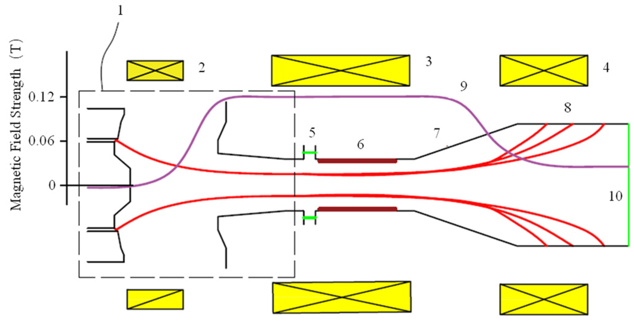
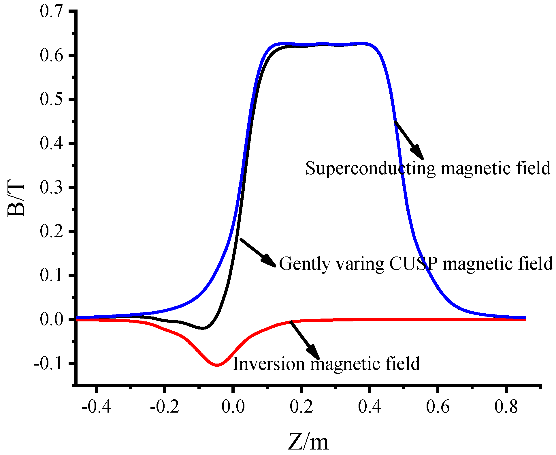
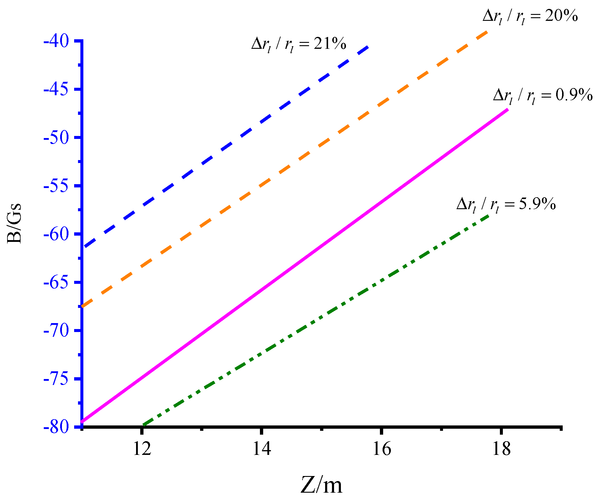
3.1. Configuration of the Magnetic Field

This paper utilizes a non-ideal cusp magnetic field to generate an axis-encircling beam. The magnetic field consists of two components: the main magnetic field and the inversion magnetic field. The main magnetic field is supplied by the existing superconducting magnet (primarily to reduce experimental costs), while the inversion magnetic field is generated by the room-temperature coil. The final distributions of the axial magnetic fields are optimized, as shown in Figure 2. The length of the cusp region is approximately 12 mm.

3.2. Optimized Design of the Electron Optical System with an Axis-Encircling Beam

To ensure the observability of the axis-encircling beam trajectory in the experiment, the original design parameters include a large-orbit beam with a voltage of 20 kV, a current of 0.5 A, and a Larmor radius of 3.3 mm. A 2-D simulation was conducted using the CHIPIC software [27]. Through extensive optimization simulations, the electrode structure was determined. The electric potential distribution near the cathode is shown in Figure 3. The structural accuracy of both the paraxial and distal axis electrodes is exceptionally high. The electrode shape requires multiple optimizations, in conjunction with the magnetic field distribution. The structure of the electrodes and the trajectory of the axis-encircling beam are illustrated in Figure 3. The guiding center spread is approximately 0.9%, and the radius of the designed large-orbit beam is about 3.3 mm, as determined by trajectory data from the MIG export, as shown in Figure 4. The detailed parameters of the optical system are provided in Table 1.

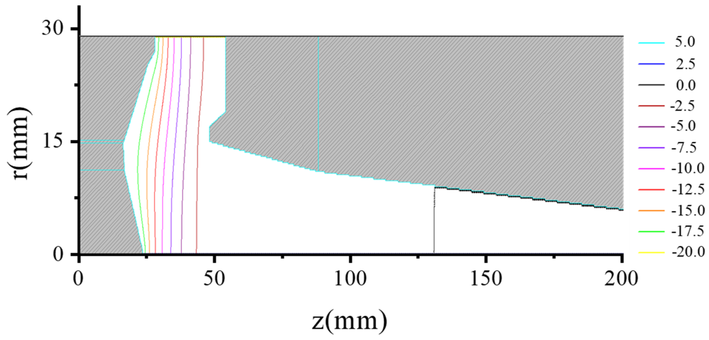
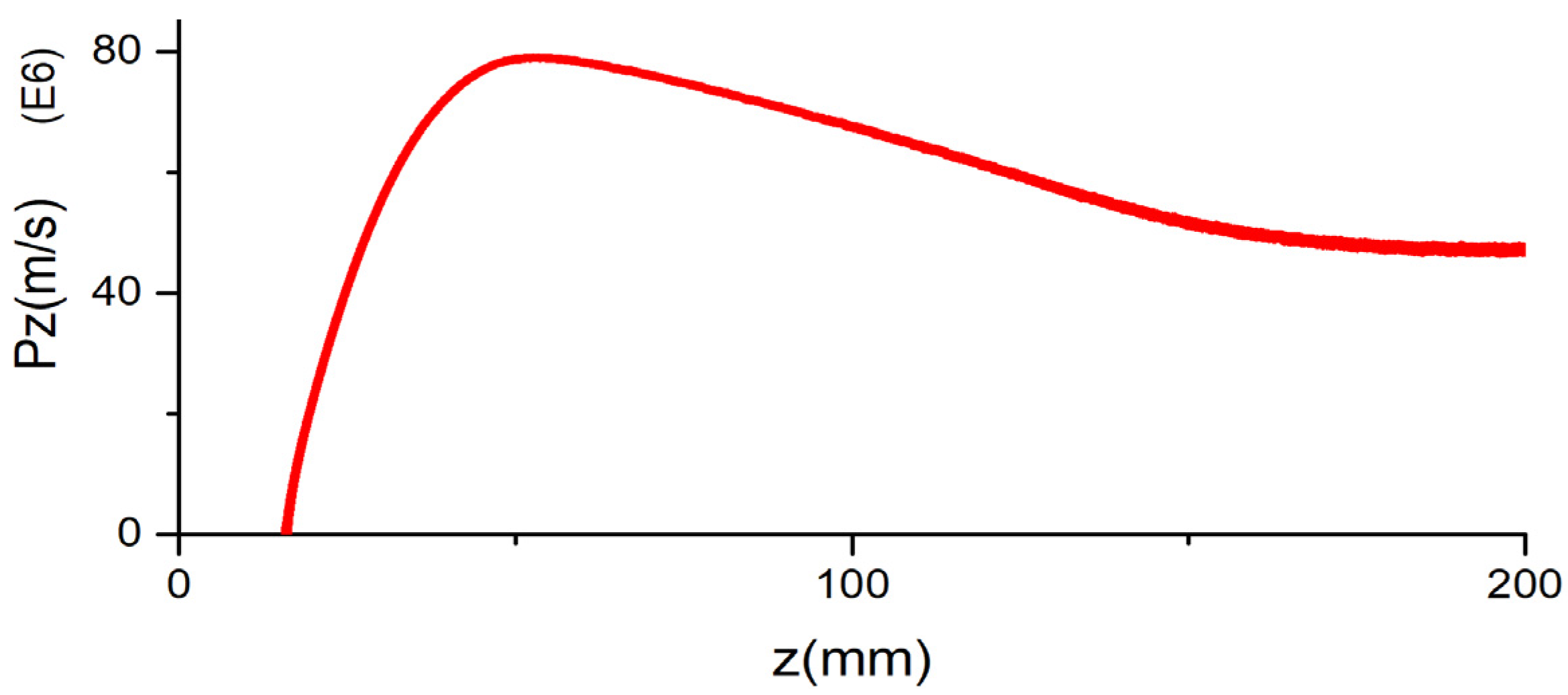
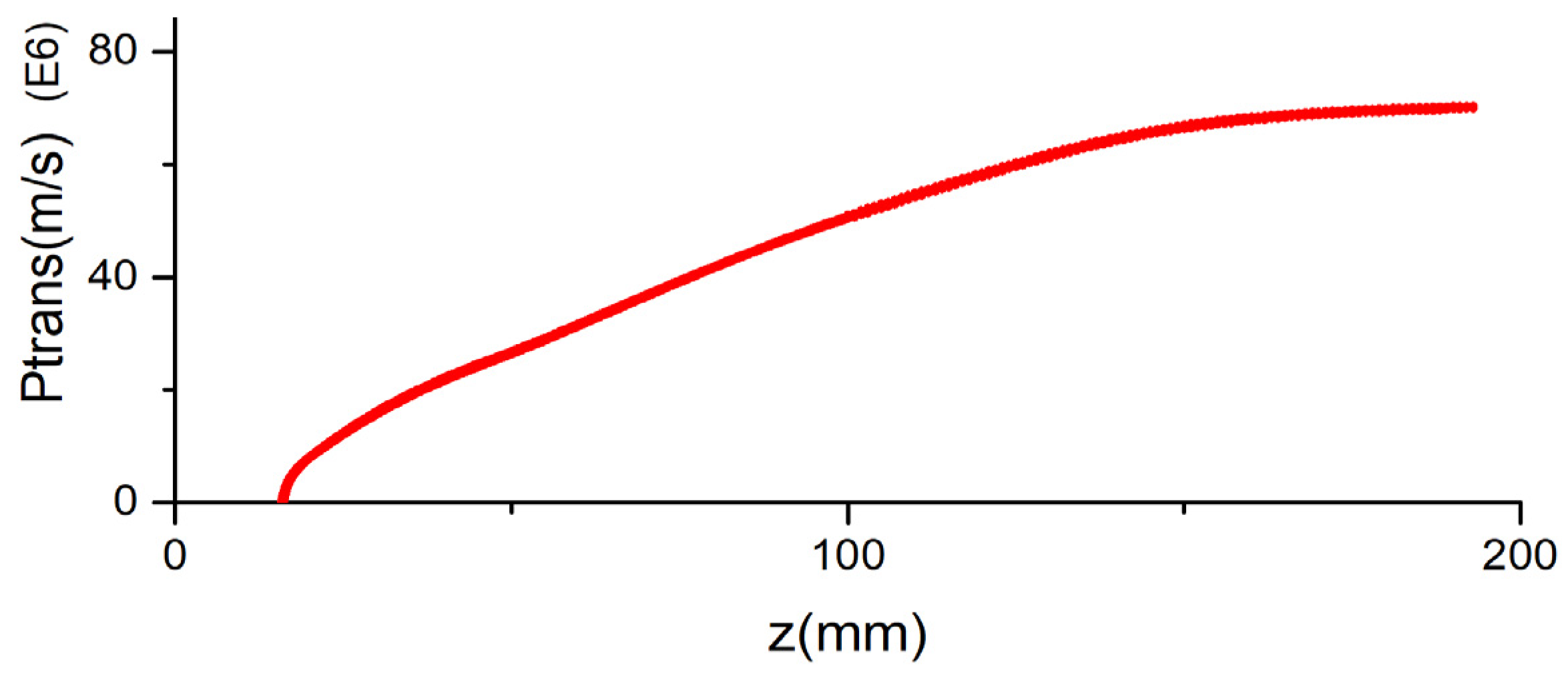
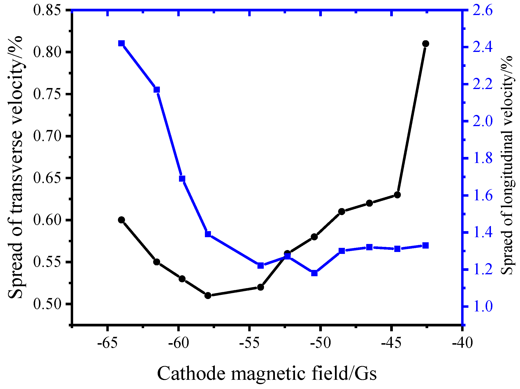
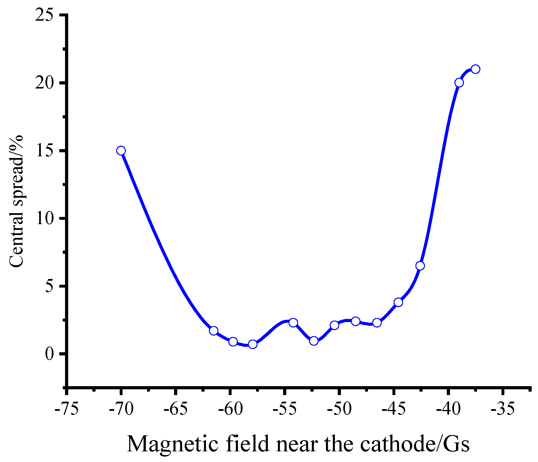
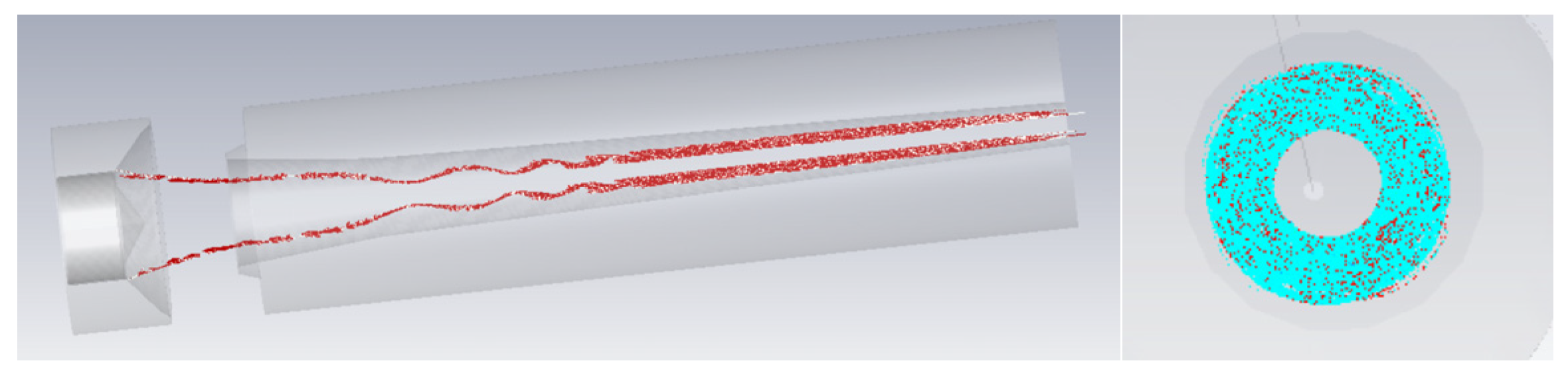
3.3. The Character of the Beam

The velocity and pitch factor spreads are also obtained from the MIG export data. The longitudinal and transverse momentums of the axis-encircling beam are shown in Figure 5 and Figure 6. The pitch factor distribution is illustrated in Figure 7. According to the simulations, the results are as follows: the transverse velocity spread is approximately 0.6%. The longitudinal velocity spread is approximately 1.2%, and the guiding center spread is approximately 0.9%. The parameters of the axis-encircling beam exhibit good consistency. The value of the cathode magnetic field determines the length of the cusp magnetic field, which directly affects beam quality. The velocity spread of the axis-encircling beam as a function of the cathode magnetic field is shown in Figure 8. The conclusion is that the beam exhibits low parameter spread when the cathode magnetic field value is between −60 and −45 Gs. The velocity spread increases significantly if the magnetic field is greater than −45 Gs or less than −60 Gs.
The distribution and value of the magnetic field near the cathode significantly impact the central spread (off-axis) of the axis-encircling beam. The central spread of the beam as a function of the magnetic field distribution is shown in Figure 9 and Figure 10. The results show that the relative central spread of the beam is approximately 0.9%. This value is close to the target beam spread when the magnetic configuration is set as the pink line in Figure 9. The conclusion is that a high-quality axis-encircling beam can be obtained when the cathode magnetic field value is between −60 and −45 Gs, and the magnetic field distribution near the cathode is carefully optimized.
The electrons gain transverse velocity mainly due to the v z × B r   force in the cusp region. An axis-encircling beam will be obtained when the v z of the electrons are above the threshold speed and the B r is strong enough. Conversely, it will be a small orbit electron beam. To prove that the beam is an axis-encircling beam, the result is studied when the cusp magnetic field is replaced with an adiabatic field, which is realized by removing the reversal magnetic field. The 3-D simulation is performed using the CST software, and the results are shown in Figure 11. It is shown that the average radius of the trajectory of the small orbit beam is distributed between 5.2 mm and 6.5 mm, which is near the wall of the gun. The result will help us distinguish between an axis-encircling beam and small orbit beam.

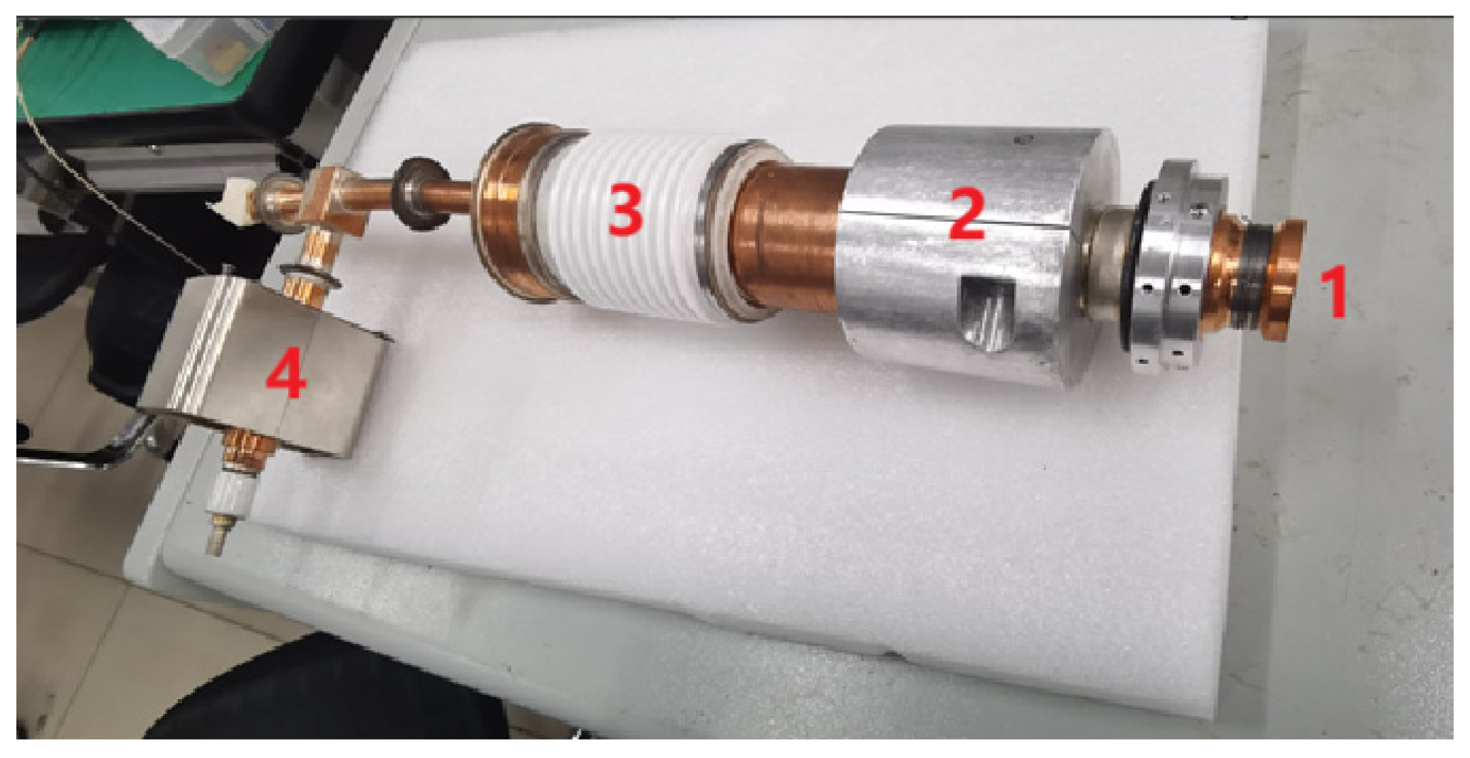
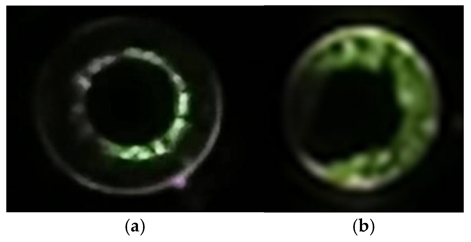
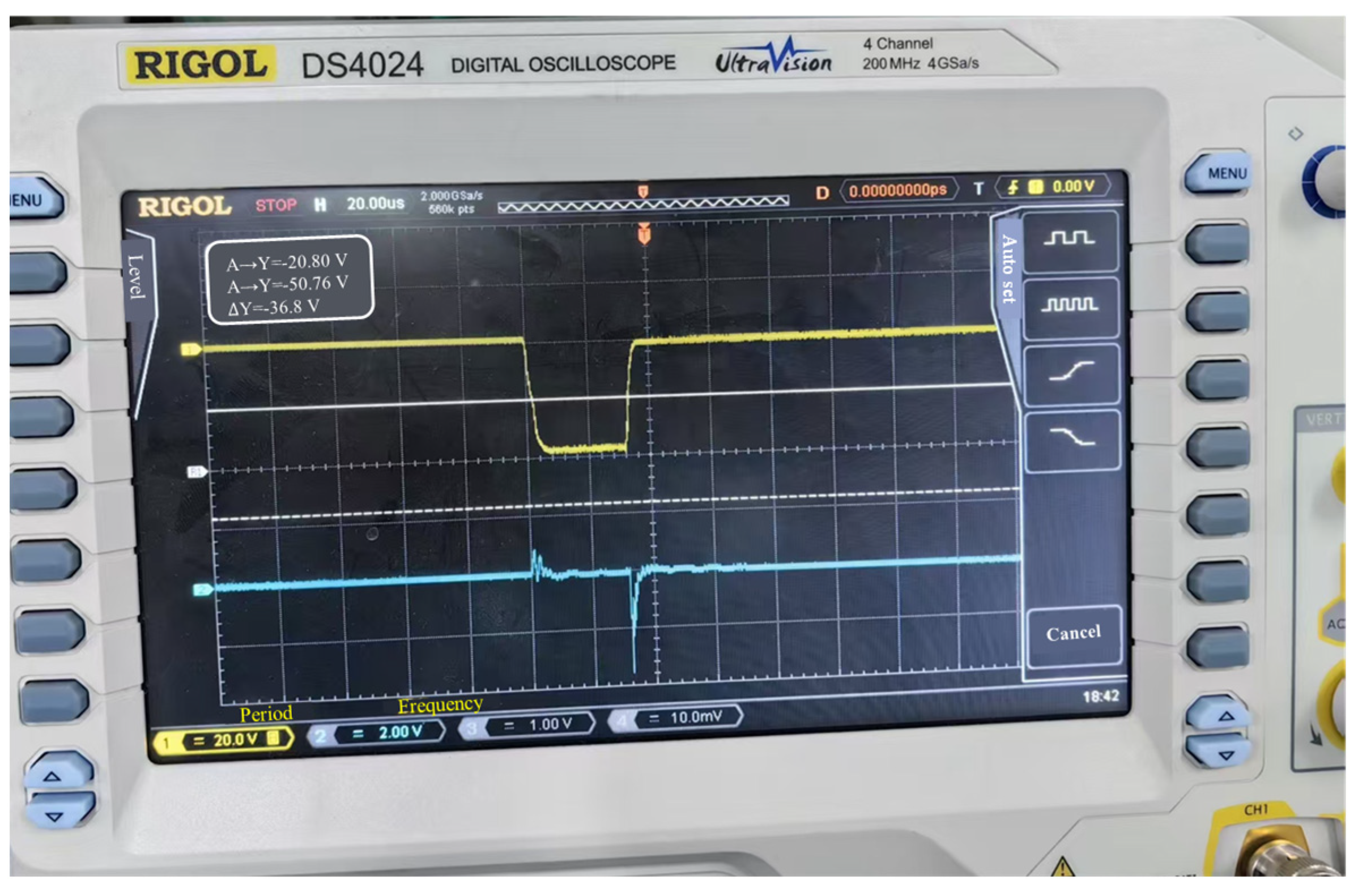
4. Experimental Research

Based on the optimized design, an MIG with an axis-encircling beam has been manufactured. The photo of the MIG is shown in Figure 12. A phosphor-coated glass plate (output window 1) is positioned at the beam exit to observe the beam’s location. The concentric mold at 2 aligns the MIG axis with the magnetic field axis. The insulating ceramic at 3 electrically isolates the cathode and anode while withstanding high voltage. The titanium getter pump at 4 maintains the required vacuum level in the MIG. During testing, the voltage and current are applied first, followed by adjusting the magnetic field by varying the current in the coils of the superconducting magnet and inversion magnetic body. The axis-encircling beam orbit is observed when the magnetic field is set to the designed value. The trajectory on the plate is shown in Figure 13a. Two fluorescent loops are visible in Figure 13a. The radius of the inner bright loop is approximately 3–4 mm. Based on the simulation results in Figure 4 from Section 3, it is certain that the inner loop represents the trajectory of the axis-encircling electron beam, as its average radius is approximately 3.5 mm. The outer semi-ring corresponds to the light emitted by the directly heated cathode, as it persists even when the voltage and current are removed. The trajectory of the small-orbit beam is observed when the inversion magnetic field is turned off. The result is shown in Figure 13b. This is confirmed by the radius of approximately 5–7 mm, which aligns well with the results in Figure 11. The waveforms observed during the test are shown in Figure 14. The waveform in the upper part (yellow) represents the beam voltage, set to 20 kV (20 V on the oscilloscope corresponds to the actual 20 kV). The waveform in the lower part (blue) represents the beam current, set to approximately 0.5 A (500 mV on the oscilloscope corresponds to the actual current of 0.5 A).

5. Conclusions

Based on theoretical and simulation studies, an axis-encircling beam with low parameter spread is achieved through the well-designed configurations of the gently varying cusp magnetic field and electrode structures. In comparison to the small-orbit spiral electron beam, the quality of the axis-encircling beam, such as pitch factor and velocity spread, is highly sensitive to the configurations of the gently varying cusp magnetic field, particularly the cathode magnetic field. The length of the cusp region should be below 14 mm; otherwise, the electron eccentricity will increase rapidly. The structural accuracy of the paraxial and distal axis electrodes is extremely high and requires extensive optimization in conjunction with the magnetic field distribution. The beam exhibits low parameter spread when the cathode magnetic field value is between −60 and −45 Gs. The velocity spread increases significantly if the magnetic field exceeds −45 Gs or falls below −60 Gs. The magnetic mirror effect easily arises when the cathode magnetic field is set too low. The length of the cusp region is another critical factor influencing the guiding-center spread. During experimental testing, different orbits are observed by adjusting the shape of the cusp magnetic field or the adiabatic field, including the small-orbit spiral electron beam when the cusp magnetic field is removed. The experimental study is in good agreement with the theoretical and simulation results. This demonstrates that a gently varying cusp magnetic field, replacing the ideal cusp magnetic field, can produce an axis-encircling beam with good parameter consistency. This research can contribute to the development of high-frequency gyro-devices operating at higher harmonics. Currently, an axis-encircling beam has been designed for a Ka-band gyro-TWT operating at the second harmonic.

Author Contributions

Conceptualization, C.L. and Q.Z.; methodology, C.L., E.W., Q.Z., S.S., D.G., S.L., Y.Z. and J.F.; data curation, C.L. and S.S.; formal analysis, Q.Z., C.L. and S.S.; writing—original draft preparation, Q.Z., C.L. and S.S.; writing—review and editing, Q.Z. and C.L.; funding acquisition, C.L., Q.Z. and J.F. All authors have read and agreed to the published version of the manuscript.

Funding

This research was funded by the Stable-Support Scientific Project of Beijing Vacuum Electronics Research Institute: K2410259, key projects of the China People’s Police University: 2019zdgg001, the National Natural Science Foundation of China: 62001131, the Dean Project of Guangxi Key Laboratory of Wireless Broadband Communication and Signal Processing Grant Nos: GXKL06190102, the Guangxi Natural Science Foundation Project: 2019GXNSFBA245066, and Guilin Science Research and Technology Development Plan Project: 20210218-3.

Data Availability Statement

Data are contained within the article.

Conflicts of Interest

Authors E’Feng Wang, Dongshuo Gao, Yichi Zhang and Jinjun Feng were employed by the company Beijing Vacuum Electronics Research Institute. The remaining authors declare that the research was conducted in the absence of any commercial or financial relationships that could be construed as a potential conflict of interest.

References

  1. Thumm, M. State-of-the-Art of High-Power Gyro-Devices and Free Electron Masers. J. Infrared Millim. Terahertz Waves 2020, 41, 1–120. [Google Scholar]
  2. Zhao, Q.; Ma, M.; Li, X.; Wang, Z.; Yu, S. The Multi-modes, Multi-harmonics Behavior of a THz Large-orbit Gyrotron. J. Infrared Millim. Waves 2022, 41, 457–1453. [Google Scholar]
  3. Sinitsyn, O.V.; Nusinovich, G.S.; Antonsen, T.M. Stability of Gyrotron Operation in very High-order Modes. Phys. Plasmas 2012, 19, 063114. [Google Scholar] [CrossRef]
  4. Thumm, M.K. Recent Advances in the Worldwide Fusion Gyrotron Development. IEEE Trans. Plasma Sci. 2014, 42, 590–1599. [Google Scholar] [CrossRef]
  5. Jelonnek, J.; Albajar, F.; Alberti, S.; Avramidis, K.; Benin, P.; Bonicelli, T.; Cismondi, F.; Erckmann, V.; Gantenbein, G.; Hesch, K.; et al. From Series Production of Gyrotrons for W7-X Toward EU-1 MW Gyrotrons for ITER. IEEE Trans. Plasma Sci. 2014, 42, 1135–11143. [Google Scholar] [CrossRef]
  6. Singh, U.; Kumar, N.; Sinha, A.K. Magnetron Injection Gun for a Short Pulse, 0.67 THz Gyrotron for Remote Detection of Radioactive Materials. IEEE Trans. Terahertz Sci. Technol. 2014, 4, 509–1514. [Google Scholar] [CrossRef]
  7. Ruess, S.; Gantenbein, G.; Illy, S.; Kobarg, T.; Pagonakis, I.G.; Rzesnicki, T.; Thumm, M.; Weggen, J.; Jelonnek, J. Tolerance Studies on an Inverse Magnetron Injection Gun for a 2-MW 170-GHz Coaxial-cavity Gyrotron. IEEE Trans. Electron Devices 2017, 64, 3870–13876. [Google Scholar] [CrossRef]
  8. Thumm, M. Gyro-devices and Their applications. In Proceedings of the 2011 IEEE International Vacuum Electronics Conference (IVEC), Bangalore, India, 21–24 February 2011; pp. 521–524. [Google Scholar]
  9. Samsonov, S.V.; Levitan, B.A.; Murzin, V.N.; Gachev, I.G.; Denisov, G.G.; Bogdashov, A.A.; Mishakin, S.V.; Fiks, A.S.; Soluyanova, E.A.; Tai, E.M.; et al. Ka-band Gyrotron Traveling-wave Tubes with the Highest Continuous-wave and Average Power. IEEE Trans. Electron Devices 2014, 61, 4264–14267. [Google Scholar] [CrossRef]
  10. Naidu, V.B.; Kesari, V.; Karmakar, S.; Seshadri, R. Particle-In-Cell Simulation of a Tapered Cavity for a Millimeter Wave Gyrotron. IEEE Trans. Plasma Sci. 2018, 46, 2460–12464. [Google Scholar] [CrossRef]
  11. Louksha, O.I.; Malkin, A.G.; Trofimov, P.A. First Experiments on Multistage Energy Recovery in a 4-mm Wavelength Gyrotron. IEEE Electron Device Lett. 2024, 45, 1638–11641. [Google Scholar] [CrossRef]
  12. Gao, J.; Li, B.; Yu, W.; Chen, Y.; Yin, H.; Xu, B.; He, W. Study of a Broadband and High-power Terahertz Gyrotron Traveling-wave Amplifier. IEEE Electron Device Lett. 2023, 44, 1744–11747. [Google Scholar] [CrossRef]
  13. Kao, S.H.; Chiu, C.C.; Pao, K.F.; Chu, K.R. Competition between Harmonic Cyclotron Maser Interactions in the Terahertz Regime. Phys. Rev. Lett. 2011, 107, 105101. [Google Scholar] [CrossRef] [PubMed]
  14. Notake, T.; Saito, T.; Tatematsu, Y.; Fujii, A.; Ogasawara, S.; Agusu, L.; Ogawa, I.; Idehara, T.; Manuilov, V.N. Development of a Novel High Power Sub-THz Second Harmonic Gyrotron. Phys. Rev. Lett. 2009, 103, 225002. [Google Scholar] [CrossRef]
  15. He, W.; Donaldson, C.R.; Zhang, L.; Ronald, K.; Phelps, A.D.R.; Cross, A.W. Broadband Amplification of Low-Terahertz Signals Using Axis-Encircling Electrons in a Helically Corrugated Interaction Region. Phys. Rev. Lett. 2017, 119, 184801.1–1184801.5. [Google Scholar] [CrossRef] [PubMed]
  16. Kiya, T.; Yamane, H.; Yamakawa, K.; Honda, N.; Ouchi, K. Recording Performance of Perpendicular Magnetic Recording Media Measured With Contact-Type Cusp-Field Write Head. IEEE Trans. Magn. 2006, 42, 2378–12380. [Google Scholar] [CrossRef]
  17. Wang, J.; Luo, Y.; Luhmann, N.C. The Simulation of a High-Power Low-Velocity-Spread Space-Charge-Limited (SCL) Cusp Gun. IEEE Trans. Plasma Sci. 2010, 38, 3356–13362. [Google Scholar] [CrossRef]
  18. Donaldson, C.R.; He, W.; Cross, A.W.; Li, F.; Phelps, A.D.R.; Zhang, L.; Ronald, K.; Robertson, C.W.; Whyte, C.G.; Young, A.R. A CUSP Electron Gun for Millimeter Wave Gyrodevices. Appl. Phys. Lett. 2010, 96, 141501. [Google Scholar] [CrossRef]
  19. Jeon, S.G.; Baik, C.W.; Kim, D.H.; Park, G.S.; Sato, N.; Yokoo, K. Study on velocity spread for axis-encircling electron beams generated by single magnetic cusp. Appl. Phys. Lett. 2002, 80, 3703–13705. [Google Scholar] [CrossRef]
  20. Du, C.H.; Chang, T.H.; Liu, P.K.; Yuan, C.P.; Yu, S.J.; Liu, G.F.; Bratman, V.L.; Glyavin, M.Y.; Kalynov, Y.K. Development of a Magnetic Cusp Gun for Terahertz Harmonic Gyrodevices. IEEE Trans. Electron Devices 2012, 59, 3635–13640. [Google Scholar] [CrossRef]
  21. Du, C.-H.; Qi, X.-B.; Hao, B.-L.; Chang, T.-H.; Liu, P.-K. Conformal Cross-Flow Axis-Encircling Electron Beam for Driving THz Harmonic Gyrotron. IEEE Electron Device Lett. 2015, 36, 960–1962. [Google Scholar] [CrossRef]
  22. Schmidt, G. Nonadiabatic Particle Motion in Axial symmetric Fields. Phys. Fluids 1962, 5, 994–11002. [Google Scholar] [CrossRef]
  23. Jaynes, R.; Gilgenbach, R.; Hochman, J.; Eidietis, N.; Rintamaki, J.; Cohen, W.; Peters, C.; Lau, Y.; Spencer, T. Velocity Ratio Measurement Diagnostics and Simulations of a Relativistic Electron Beam in an Axis Encircling Gyrotron. IEEE Trans. Plasma Sci. 1999, 27, 136–1137. [Google Scholar] [CrossRef]
  24. Scheitrum, G.P.; Symons, R.S.; True, R.B. Low velocity spread axis encircling electron beam forming system. In Proceedings of the International Technical Digest on Electron Devices Meeting, Washington, DC, USA, 3–6 December 1989; pp. 743–1746. [Google Scholar]
  25. Wu, X. Study of the Forming Technology and Application of Larage-Orbit Electron Beam. Ph.D. Thesis, University of Electronic Science and Technology of China, Chengdu, China, 2013; pp. 20–30. [Google Scholar]
  26. MJRhee, W.W. Destler. Relativistic electron dynamics in a cusped magnetic field. Phys. Fluids 1974, 17, 1574–1581. [Google Scholar]
  27. Zhou, J.; Liu, D.; Liao, C.; Li, Z. CHIPIC: An Efficient Code for Electromagnetic PIC Modeling and Simulation. IEEE Trans. Plasma Sci. 2009, 37, 2002–2011. [Google Scholar] [CrossRef]
Figure 1. The major component of a gyro-TWT (1—cusp gun; 2—reverse coil; 3—cavity coil; 4—collector coil; 5—input window; 6—high-frequency structure; 7—mode converter; 8—collector; 9—gently varying magnetic field; 10—output window).
Electronics 14 00390 g001
Figure 2. The distribution of an axial magnetic field.
Electronics 14 00390 g002
Figure 3. The distribution of the electric potential.
Electronics 14 00390 g003
Figure 4. The structure of electrodes and the trajectory of the axis-encircling beam.
Electronics 14 00390 g004
Figure 5. The distribution of the longitudinal momentums of the beam along the z-axis.
Electronics 14 00390 g005
Figure 6. The distribution of the transverse momentums of the beam along the z-axis.
Electronics 14 00390 g006
Figure 7. The distribution of the pitch factor of the beam along the z-axis.
Electronics 14 00390 g007
Figure 8. The velocity spread of the beam vs. the cathode magnetic field.
Electronics 14 00390 g008
Figure 9. The central spread of the beam changes with the distribution of magnetic field near the cathode.
Electronics 14 00390 g009
Figure 10. The central spread of the beam changes with the magnetic field near the cathode.
Electronics 14 00390 g010
Figure 11. The structure and the trajectory of the small orbit beam.
Electronics 14 00390 g011
Figure 12. The photo of the MIG. (1—output window; 2—concentric mold of magnetic field and electron beam; 3—insulating ceramic; 4—titanium getter pump).
Electronics 14 00390 g012
Figure 13. (a) The orbit of the axis-encircling beam at the exit of the MIG in the experiment; and (b) the small orbit beam at the exit of the MIG in the experiment.
Electronics 14 00390 g013
Figure 14. Voltage and current waveform in the test. (1—waveform of the beam voltage; 2—waveform of the beam current).
Electronics 14 00390 g014
Table 1. Parameters of the optical system with an axis-encircling beam.
The Name of ParametersValue
Beam voltage20 kV
Beam current0.5 A
Magnetic field0.122 T
Cathode radius15 mm
Pitch factor1.5
Current density0.94 A/cm2
Larmor radius3.3 mm
Transverse velocity spread Δ v / v = 0.6%
Longitudinal velocity spread Δ v z / v z = 1.2%
Guiding center spread Δ r L / r L = 0.9%
Disclaimer/Publisher’s Note: The statements, opinions and data contained in all publications are solely those of the individual author(s) and contributor(s) and not of MDPI and/or the editor(s). MDPI and/or the editor(s) disclaim responsibility for any injury to people or property resulting from any ideas, methods, instructions or products referred to in the content.

