Abstract
We present a three-dimensional, additively manufactured microstrip balun design for the balanced feeding of wearable antennas. Extensive research has been performed regarding wearable antennas, but the balun design is often ignored. The balun may be omitted, a commercial off-the-shelf balun may be used, or a bulky microstrip balun may be implemented; however, these options are either incorrect or add a significant size to the antenna that is not acceptable for wearable applications. We propose a three-dimensional, conformal microstrip balun enabled by additive manufacturing (AM) technology, and demonstrate its performance using the wearable High-Contrast Low-Loss Antenna (HCLA) as an example. First, the electromagnetic properties of potential substrate materials are characterized from 0.5 to 3 GHz. Exponential tapered baluns are designed, simulated, and tested in a back-to-back configuration to verify the measured material properties for the substrates. Then, the baluns are integrated with the HCLA using a conformal configuration. The measurement results from 0.5 to 3 GHz on the phantoms agree with the simulation for both the reflection coefficient and transmission loss. Importantly, the proposed balun allows the antenna to be used in wearable applications, where balun size would have previously hindered its implementation. The flexibility of the proposed design also allows for the integration with other antennas aside from the HCLA.
1. Introduction
Wearable antennas are an enabling technology for a variety of applications, from wireless communication systems to next-generation medical sensing and diagnostics. Some wearable systems require antennas that radiate away from the body, such as smartwatches connecting to Bluetooth or cellular networks [1], or wireless body area networks (WBANs) connecting multiple nodes of sensors across the body [2]. Other wearable systems necessitate antennas that radiate toward the body, such as antennas for telemetry with a medical implant [3], medical radiometry [4], or medical microwave imaging [5]. Extensive research has been performed regarding the design of wearable antennas for various off-body and into-body applications [6,7].
Many of these wearable antennas are balanced antennas (e.g., dipoles, bowties, and spirals) that require a balun for proper feeding. The baluns, however, are often bulky in size and hinder the wearability of the system. The use of traditional substrate materials (e.g., Rogers materials) limits their implementation in applications where conformality or flexible materials are of interest. In this work, we aim to answer the following research questions: (a) can we configure a microstrip balun in an unconventional orientation without impacting antenna performance? and (b) what non-traditional materials can be used effectively for balun substrates in terms of both electromagnetic and physical properties?
To address these questions and overcome the limitations of the current state of the art, we propose a new class of conformal baluns that are enabled by additive manufacturing (AM) technology. Without the loss of generality, we demonstrate a conformal-microstrip-tapered balun for the High-Contrast Low-Loss Antenna (HCLA): a wearable antenna optimized for into-body radiation [8]. The HCLA was selected as an example because it has a wide bandwidth and its three-dimensional, pyramidal-shaped dielectric poses a significant challenge for balun design. Importantly, the developed knowledgebase from this example expands to diverse wearable and conformal antennas (e.g., different shapes, frequencies, materials, etc.) because of the AM design.
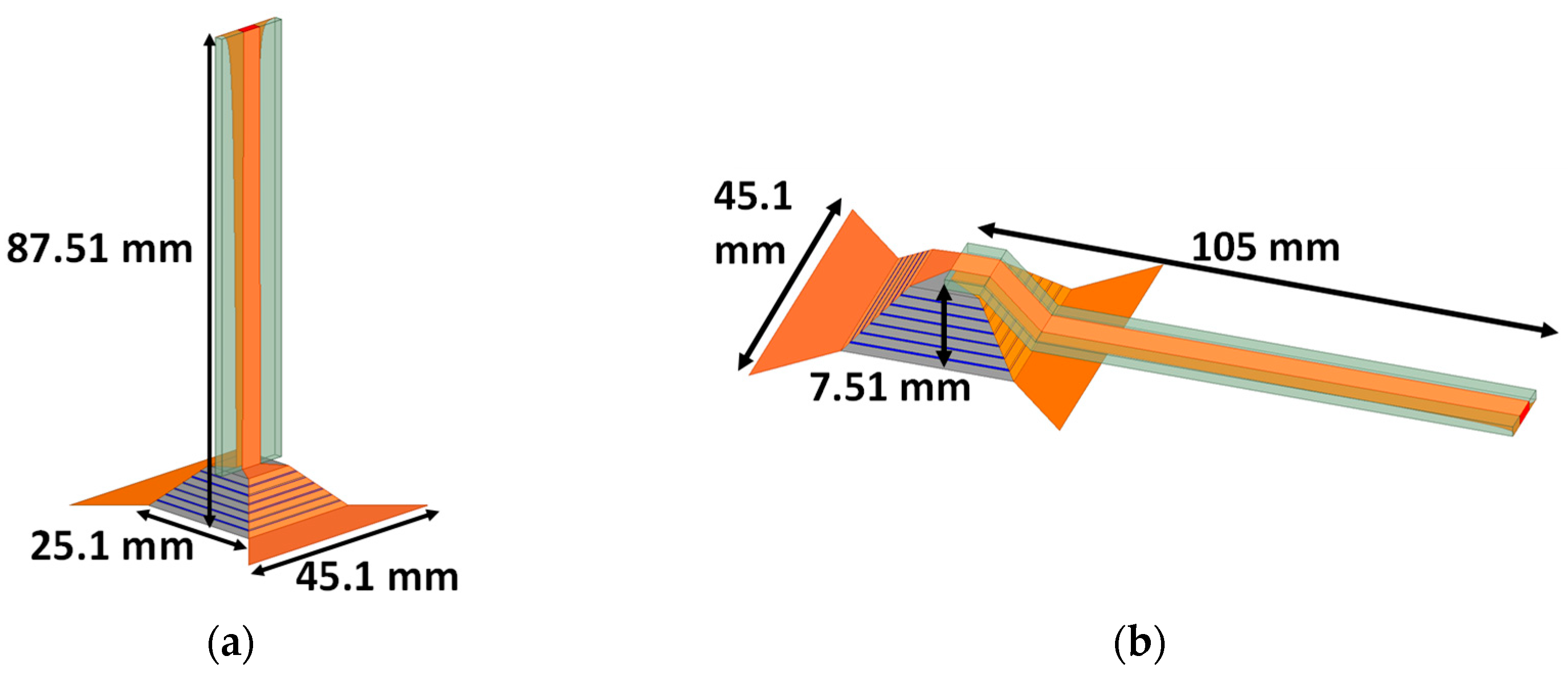
For the HCLA, if the balun is integrated perpendicular to the antenna arms, the antenna would be tall and unsuitable for wearable applications, as shown in Figure 1a. Thus, we propose that the balun could be fabricated such that it conforms to the 3D shape of the antenna, as shown in Figure 1b. To meet these requirements, the microstrip substrate was fabricated from commercially available resins for stereolithography (SLA) 3D printing and/or flexible polymers. The electromagnetic properties of various resins and polymers are characterized for the first time from 500 MHz to 3 GHz. In terms of the performance, the balun should have a low reflection coefficient (|S11| < −15 dB) across the bandwidth (in this case, 500 MHz to 3 GHz) and minimal insertion loss (|S21| < −2 dB). To the best of our knowledge, no microstrip balun has been designed and integrated in a conformal orientation (Figure 1b). This balun also offers improvements in bandwidth and a reduction in size compared to previous state-of-the-art wearable baluns.

Figure 1.
(a) Perpendicular and (b) conformal orientation for integrating the microstrip-to-parallel-strip-line balun with the HCLA.
In summary, the contributions of our work are as follows:
- The development of an additively manufactured, three-dimensional balun that can be altered in shape and size for use with many antennas in various applications.
- The implementation of the balun in a conformal configuration with the HCLA, such that a previously bulky antenna can be used in wearable applications.
- The electromagnetic characterization of additively manufactured substrate materials from 500 MHz to 3 GHz.
2. Literature Review
Table 1 provides an overview of baluns reported in the literature for both wearable and general balanced antennas. Table 1 presents the type of antenna (and if it is used for wearable applications or not), the frequency in terms of the −10 dB bandwidth for the antenna integrated with the balun, the type of balun used, the balun size (given in length by width by height), the average insertion loss across the frequency range, and the material used for the substrate. Table 1 also compares the conformality of the baluns, where “No” means the balun is perpendicular to the antenna arms, as in Figure 1a, and “Yes” means the balun is in the same plane as the antenna arms, as in Figure 1b.

Table 1.
Comparison of the baluns reported in the literature versus the proposed approach.
In [9], wearable dipole antennas were embroidered using various textiles, but the coaxial connector was soldered directly to the feed without a balun. Some wearable antennas implement commercial off-the-shelf baluns that add considerable bulk to the antenna. For example, an origami e-textile dipole antenna [10], a tightly coupled e-thread dipole array [11], and a quasi-bowtie antenna for into-body radiation [8], which were commercial baluns used without any further consideration of size or performance. In [12], a spiral antenna was integrated with a tapered balun; however, the balun design was only applicable to spiral antennas and the substrate was rigid. In [13], a microstrip-to-parallel-strip-line balun was developed for microwave imaging applications; however, the orientation of the balun (i.e., like that of Figure 1a) added significant size to the imaging system. In [14], a conformal microstrip-to-coplanar-line balun was designed for wearable RFID tags, but the snap-on button design degraded the performance.
Indeed, even general-purpose (i.e., not necessarily wearable) balanced antennas suffer limitations from the balun. In [15], a microstrip-to-parallel-strip-line balun was designed for feeding a cavity-backed folded triangular bowtie antenna, and, in [16], a microstrip-to-parallel-strip balun was miniaturized via bending to feed an Archimedes spiral antenna. Both of these line baluns were configured in the perpendicular orientation (i.e., like that of Figure 1a), which added significant size to an otherwise conformal antenna structure. In [17], a microstrip-to-coplanar-strip-line balun was developed using vias to feed a broadband microstrip antenna from 5 to 20 GHz. This design would be difficult to achieve on non-traditional substrates because of the required vias. In [18], a microstrip-to-coplanar-line balun was designed with a 180° phase shifter to achieve a balanced feed for a flexible bowtie antenna; however, the phase shifter was inherently narrowband.
It is difficult to perform a comprehensive comparison of balun performance for the references listed in Table 1. Many of the references provide metrics solely for the antenna integrated with the balun and omit metrics for the balun on its own. We have included these references, however, to demonstrate the size and conformality limitations of the antennas and their baluns, as the form factor often prohibits the implementation of such baluns for wearable applications.
3. Methodology
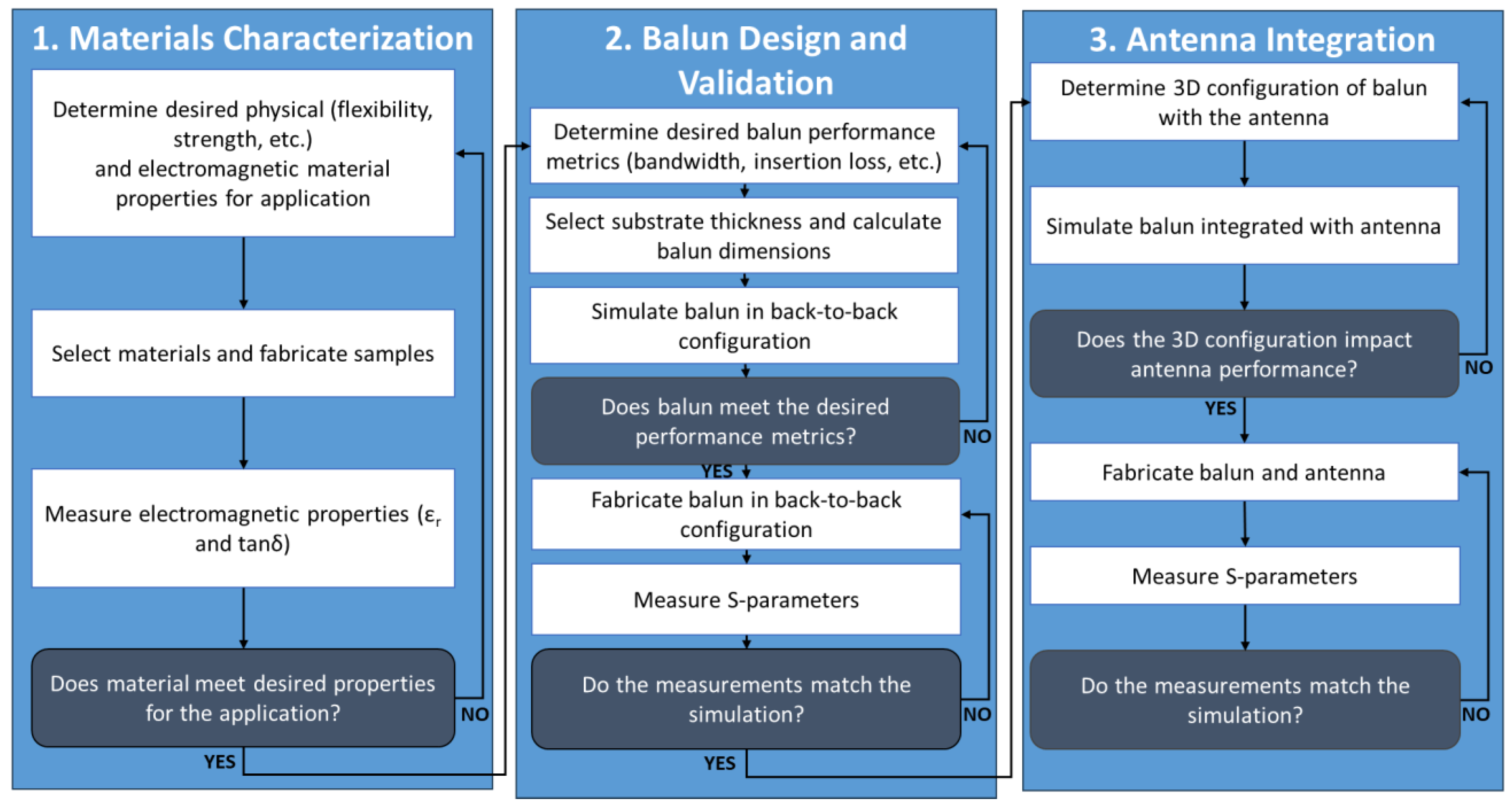
The methodology used for this research is outlined in Figure 2 and can be described in the following three steps: (1) materials characterization, (2) balun design and validation, and (3) antenna integration. First, the material properties for the application, in terms of both the physical and electromagnetic characteristics, were defined. Various applications could require different materials based on the strength, flexibility, configuration, or frequency. Then, the materials were collected, and the electromagnetic properties of the materials were measured. If the material satisfied the desired properties, the substrate could be used for the balun design and validation.
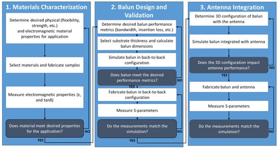
Figure 2.
Flowchart demonstrating the methodology for this research.
The performance metrics for the balun, such as the bandwidth, reflection coefficient, and insertion loss, were determined. The substrate thickness was determined based on the ease of fabrication, and the related balun parameters were calculated. The balun was simulated in Ansys 2022 R1 High Frequency Simulation Software (HFSS) to verify that the performance metrics were met. Then, the baluns were fabricated and the S-parameters were measured with a vector network analyzer. After confirming that the measurements matched closely to the simulations, the balun could be integrated with the antenna.
Lastly, the 3D configuration of the balun with the antenna was determined, and the balun integrated with the antenna was simulated in electromagnetic simulation software. The simulation results were analyzed to determine that the balun could be implemented in the 3D, conformal configuration without significantly impacting the performance of the antenna. Then, the final antenna and balun were fabricated, and the S-parameters were measured using a Keysight FieldFox N9914B (Santa Rosa, CA, USA) vector network analyzer. The measurements were validated with the simulation results.
The methodology for materials characterization and balun design (as seen in Figure 2) can be applied to any material. The specific materials listed in this paper are selected as indicative examples. This methodology is also not limited to the HCLA and could be applied to a variety of antennas.
4. Substrate Characterization
Since the balun will conform to the pyramidal shape of the HCLA, we cannot use traditional rigid substrates, such as FR4 [19] or Rogers [20]. Instead, we can easily create substrates with complex shapes using AM. For example, we can 3D print with solid resins to match the shape of the HCLA, or we can 3D print molds to easily fabricate polymer substrates that conform to the shape of the HCLA. In this section, we will characterize several potential substrates with unknown electromagnetic properties.
Formlabs resins and PDMS are selected for their availability, affordability, and physical properties. Formlabs has unique materials that are flexible, biocompatible, and of high quality (e.g., Formlabs Flexible 80A and Formlabs Elastic 50A (Somerville, MA, USA)). Rogers Radix is an emerging material that is optimized for RF applications; however, the high cost of both the resin and the required printer are prohibitive at this point. The different resins—Clear, Rigid 4000, Elastic 50A, and Flexible 80A—were selected for their varying physical properties. The Clear and Rigid 4000 resins are stiff materials with limited stretching capabilities but high tensile strengths of 65 MPa and 75 MPa, respectively. The Elastic 50A and Flexible 80A are flexible, stretchable materials with elongations at failure of 160% and 85%, respectively, but low tensile strengths of 3.23 MPa and 8.5 MPa, respectively [21]. Polydimethylsiloxane (PDMS) was also characterized in this section because it was a good candidate for a polymer substrate. The strength and stretching capabilities of PDMS varies on the thickness and mixing ratio of the polymer. Formlabs resins have not been widely characterized for use with antennas or other microwave circuits. In [22], Clear was characterized from 2.2 to 3.3 GHz using a WR340 waveguide, and, in [23], Flexible 80A was characterized up to 6 GHz using the T-resonator method. Other materials and frequencies have not been explored.
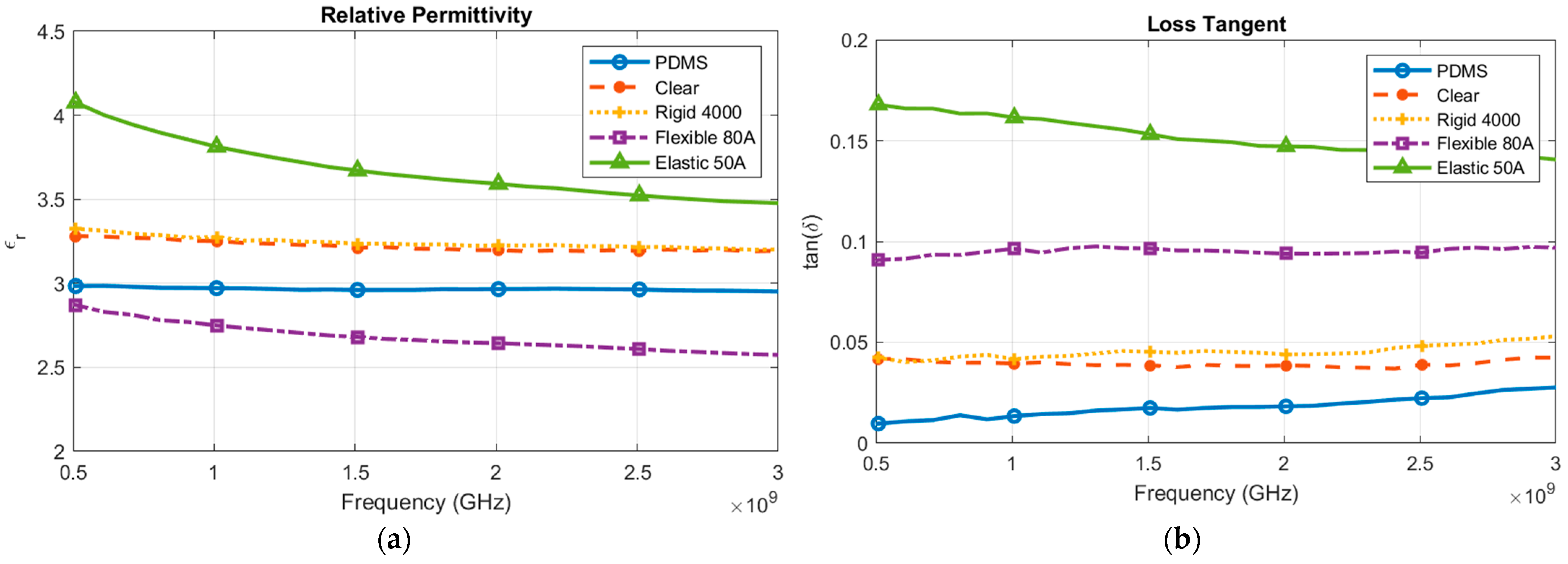
Materials characterization was performed using the Keysight N1501A high-temperature dielectric probe kit [24]. The resins were printed and the PDMS was fabricated into cubes of the correct size based on the dielectric probe requirements. The characterization of the materials in terms of the relative permittivity and loss tangent is displayed in Figure 3. As seen, all of the materials had a relative permittivity (εr) between 2 and 4, as shown in Figure 3a. The Flexible and Elastic printer resins had a high loss tangent (tanδ) near or above 0.1, as shown in Figure 3b. The solid resins (i.e., Clear and Rigid) had a lower loss tangent than the flexible resins. PDMS also had a low loss tangent, as expected from previous work [25]. The material measurements will be verified via simulation and measurement in Section 5.
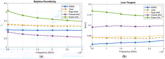
Figure 3.
Measured (a) relative permittivity (εr) and (b) loss tangent (tanδ) of various substrate materials.
5. Balun Design, Simulation, and Measurement
5.1. Balun Design
A microstrip balun was selected for feeding the HCLA because of its wideband operation and small form factor. In particular, an exponential tapered microstrip-to-parallel-strip-line balun [13] was preferable to a microstrip-to-coplanar balun [17] or Marchand balun [26] because the design simplicity allows for the integration on three-dimensional and flexible substrates. Additionally, the exponential tapered microstrip balun had ideal balanced port orientations for connecting to the balanced feed of the HCLA and did not require any vias. The balun converts an unbalanced microstrip line to a balanced parallel strip line while providing a gradual impedance taper. The SMA launcher was a 50 Ω port and the HCLA feed was a 75 Ω port. The width (W) of the parallel strip line is given by
where η is the intrinsic impedance of the substrate, d is the substrate thickness, and Z is the characteristic impedance. The width of the microstrip line can be calculated using the equations given in [27]. The exponential impedance taper is given by
where Z0 is the impedance at the start of the tapered line with length L, ZL is the impedance at the end of the tapered line, and a is a constant.
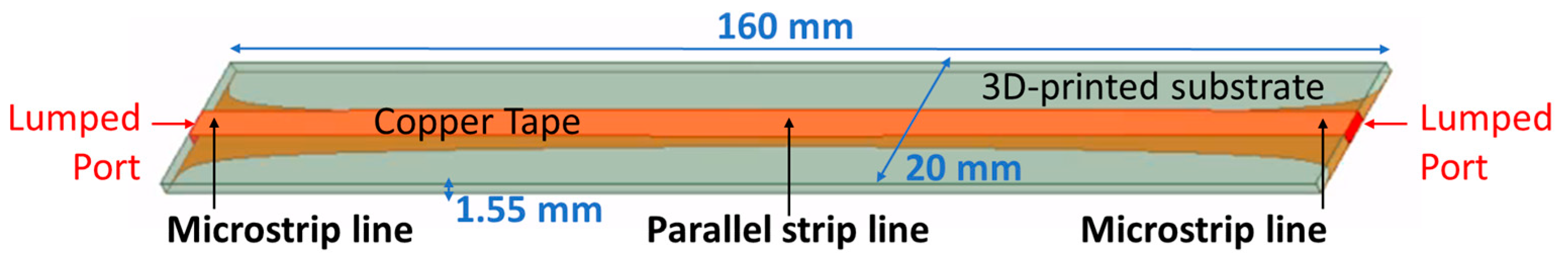
The length of the balun was determined by the wavelength of the lowest operating frequency. Here, the balun was 160 mm long in the back-to-back configuration to support frequencies below 500 MHz. The width was 20 mm to support a sufficient ground plane at the microstrip ends. The substrate was 1.55 mm thick to accommodate standard SMA launchers at the ports. The substrate thickness can be altered without affecting the balun performance based on the fabrication requirements. Variations in the substrate thickness from the fabrication tolerances may impact the balun and/or antenna performance. However, in this case, the fabrication tolerances are small and have minimal impact. The material properties, line widths required for the microstrip and parallel strip, and physical properties for each substrate are displayed in Table 2. Finally, the primary design goals for the balun were determined to be a minimized reflection coefficient (|S11| < −15 dB), a low insertion loss (|S21| < −2 dB), and a size that is conducive for wearable applications.
Table 2.
Substrate materials and balun characteristics.
5.2. Balun Simulation
The baluns were simulated in a back-to-back configuration in Ansys 2022 R1 High Frequency Simulation Software (HFSS) [28]. The simulation setup is displayed in Figure 4. The substrate is 160 mm × 20 mm × 1.55 mm in size. The microstrip lines are at both ends of the substrate while the parallel strip line is in the middle. The balun is fed by lumped ports at both ends to simulate the SMA connectors. The measured properties from Section 4 were imported as material properties for the 3D-printed substrate. The simulated results are displayed in Figure 5.
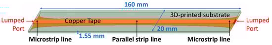
Figure 4.
Simulated layout of the back-to-back tapered balun.
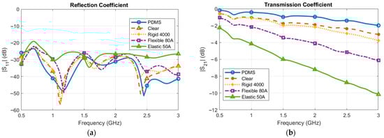
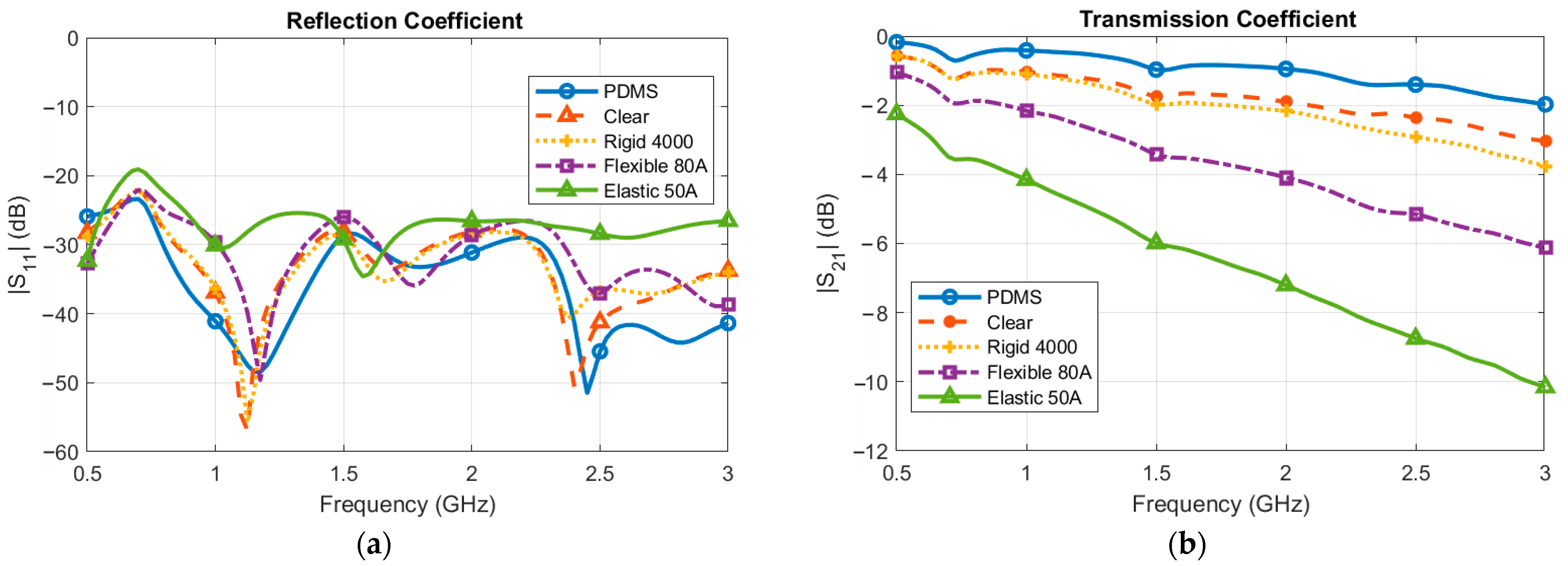
Figure 5.
Simulated (a) reflection coefficient and (b) transmission coefficient of the back-to-back balun with various substrates.
In terms of the simulated reflection coefficient, |S11|, all of the baluns performed exceptionally well. The |S11| was below −20 dB across the bandwidth for all of the substrates, except for Elastic 50A. For Elastic 50A, the |S11| was below −20 dB, except for the 650–750 MHz range. This minimal reflection coefficient indicated the baluns are well matched and the power was effectively delivered to the device. There was more variation in the simulated transmission coefficient, |S21|, of the baluns. In this case, the transmission coefficient can also be considered the insertion loss of the balun. Substrates with a higher measured loss tangent (e.g., Elastic 50A and Flexible 80A) inserted more loss into the system than substrates with a lower loss tangent (e.g., Clear and PDMS).
5.3. Balun Fabrication
The baluns (i.e., Clear, Rigid, Flexible, and Elastic) were designed in Ansys HFSS and 3D printed using a Formlabs Form 2 desktop printer [29]. The Form 2 is a stereolithography (SLA) printer that uses a light source to cure liquid resin into three-dimensional objects. The 3D printing process involved several steps, including (1) printing substrates with the various resins, (2) washing the substrates with isopropyl alcohol to remove the uncured resin, and (3) curing the substrates with both heat and light. The baluns were printed with a layer thickness of 50 µm, which allowed for accurate and high-quality prints. To fabricate the PDMS balun, first, a mold was 3D printed using the Clear resin. Then, the silicone base and curing agent were mixed together in a 10:1 ratio and poured into the mold. The mixture was left to cure in air for 48 h to ensure that there were no air bubbles in the substrate that would impact the dielectric properties.
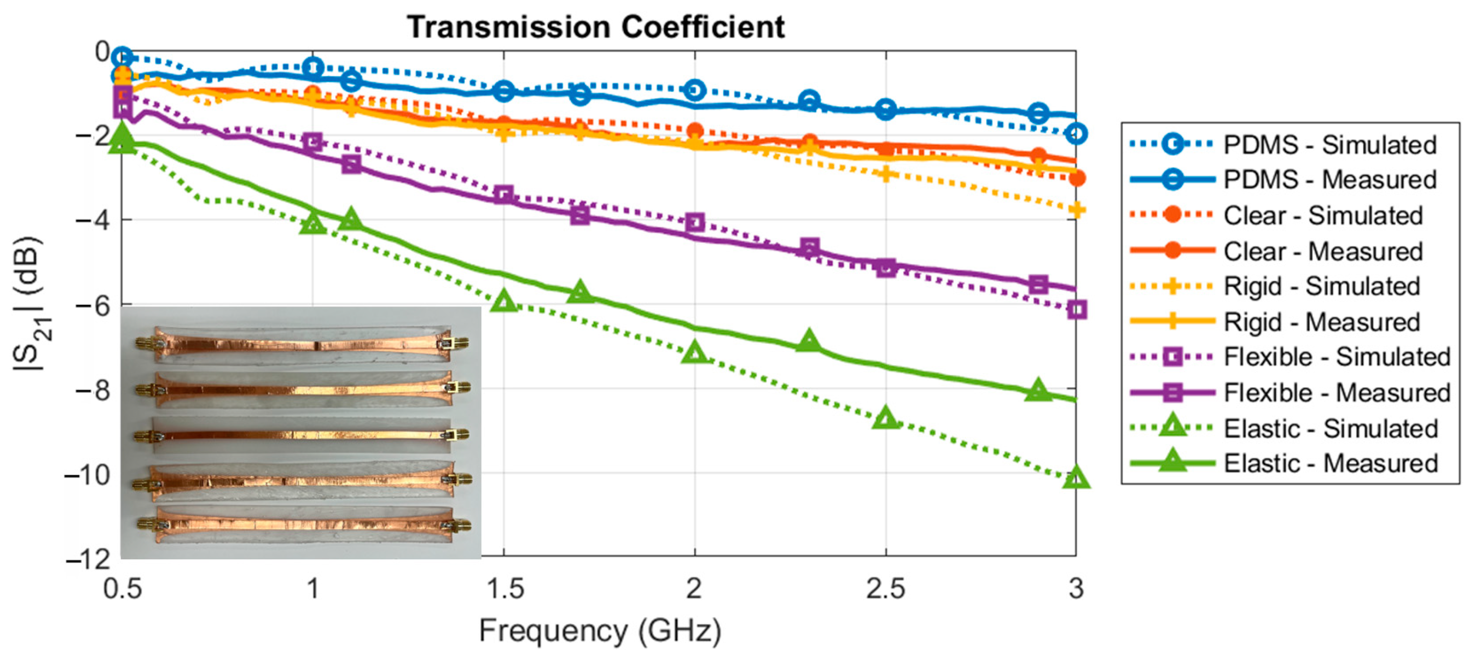
After fabricating the individual substrates, the conductors were cut from copper tape using an automated cutting machine. The copper tape was placed on the substrates, and the SMA launchers were soldered to the copper tape, as seen in Figure 6. Copper tape was used for the conductors because it is easy to fabricate for prototypes, highly conductive, and flexible. Copper tape has also demonstrated comparable electromagnetic performance to screen printing or etched aluminum [30]. Though conductive inks could also be used as an alternative, they are prone to cracking when placed on flexible substrates (i.e., PDMS, Flexible 80A, or Elastic 50A). The final fabricated baluns can be seen in the inset of Figure 7.
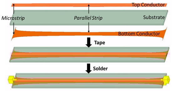
Figure 6.
Fabrication process for the back-to-back baluns with 3D-printed substrates.
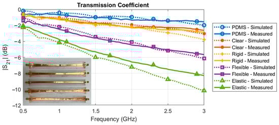
Figure 7.
Simulated vs. measured transmission coefficient of the fabricated back-to-back balun with various substrates.
5.4. Balun Measurement
The S-parameters of the back-to-back baluns were measured using a FieldFox network analyzer. The measured transmission coefficient, |S21|, results are displayed in Figure 7. For all of the baluns, the simulated and measured |S21|results matched very well across the bandwidth. The measured reflection coefficient, |S11|, results are displayed in Figure 8. For clarity, only the two substrates with the lowest insertion loss (i.e., Clear and PDMS) are seen. For all of the measured substrates, the measured reflection coefficient was higher than the simulated reflection coefficient. The measured reflection coefficient, however, was below −15 dB across the majority of the bandwidth, meaning that less than 3.1% of the power in the system was being reflected. Below −20 dB, greater than 99% of the power was being transmitted in the system (i.e., less than 1% was reflected); thus, the differences between the simulation and measurement were minor in terms of the overall system performance. For both |S11| and |S21|, the differences could be attributed to a variety of factors related to the manual fabrication process. Variations in the substrate thickness, copper tape widths, copper tape placement, and soldering could have impacted the overall results compared to the ideal simulation environment. Additionally, for the flexible substrates, any bending during the measurement could have further contributed to the differences.
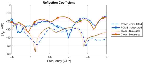
Figure 8.
Simulated vs. measured reflection coefficient of the fabricated PDMS and Clear back-to-back baluns.
Since we would like the balun to have minimal insertion loss, we herewith advanced with the Clear and PDMS baluns for the integration with the optimized HCLA. The PDMS was the best flexible option for conforming to the HCLA and the curvature of the body. The Clear balun was the best rigid option that allowed for increased mechanical stability. By doing so, we achieved our design goals of a minimized reflection coefficient (|S11| < −15 dB). Additionally, because the baluns were in the back-to-back configuration, the insertion loss illustrated in Figure 7 was for the two baluns. Thus, we achieved our goal of a low insertion loss (|S21| < −2 dB) for both the PDMS and Clear baluns.
6. Balun and Antenna Integration
6.1. Balun and Antenna Simulation
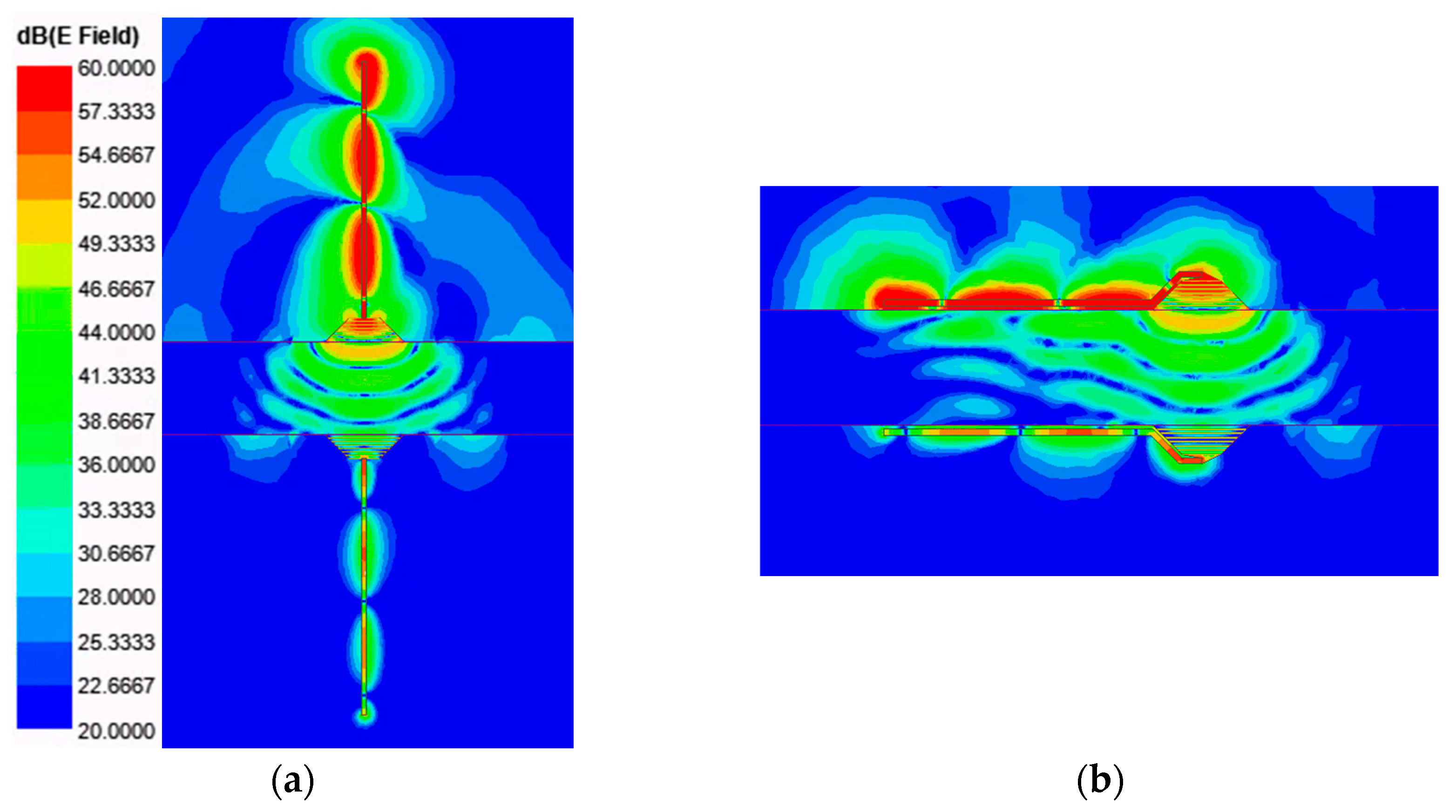
There were the following two potential orientations for the balun to feed the HCLA: perpendicular and conformal (Figure 1). The balun integrated with the HCLA was simulated in both orientations in Ansys HFSS. First, we analyzed the simulated electric fields of the two Clear balun configurations to gain insight into the different orientations. In Figure 9, the magnitude of the electric field at 3 GHz is displayed for both the perpendicular (Figure 9a) and conformal (Figure 9b) configurations. It can be seen in Figure 9 that there was some coupling that occurred between the conformal balun and the tissue prior to the antenna. However, the field patterns and the magnitude of the fields were nearly identical in the tissue region directly between the antennas.
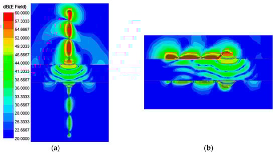
Figure 9.
Simulated electric field patterns of the HCLA at 3 GHz with the integrated (a) perpendicular and (b) conformal baluns.
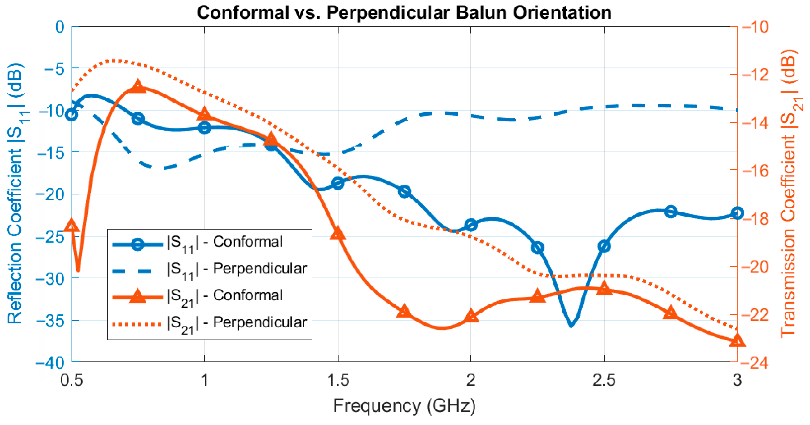
The simulated S-parameter results for the Clear balun integrated with the antenna are displayed in Figure 10. In terms of the reflection coefficient, |S11|, the conformal balun significantly outperformed the perpendicular balun across the bandwidth. In the perpendicular orientation, the width of the feed gap was the same as the width of the balun substrate (i.e., 1.55 mm). This feed gap between the two balanced arms of the antenna was too large in the perpendicular orientation and significantly degraded performance of the antenna; however, thinner substrates would have been more difficult to fabricate and implement. In terms of the transmission coefficient, |S21|, the conformal balun and the perpendicular balun had comparable performance. The conformal balun had slightly lower transmission loss because of its orientation, where the balun was placed near the tissue. There was some coupling between the balun and tissue that did not occur in free space (i.e., the perpendicular orientation), as shown in Figure 9a. However, the benefits of the conformal orientation in terms of the reflection coefficient performance and wearability far outweighed the slight reduction in the transmission coefficient. That is, there was a compromise to be made between wearability and performance.
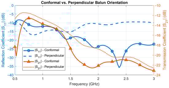
Figure 10.
Simulated reflection and transmission coefficient for the Clear balun integrated with the antenna in the conformal (solid lines) and the perpendicular (dashed lines) orientations.
6.2. Antenna Fabrication and Experimental Setup
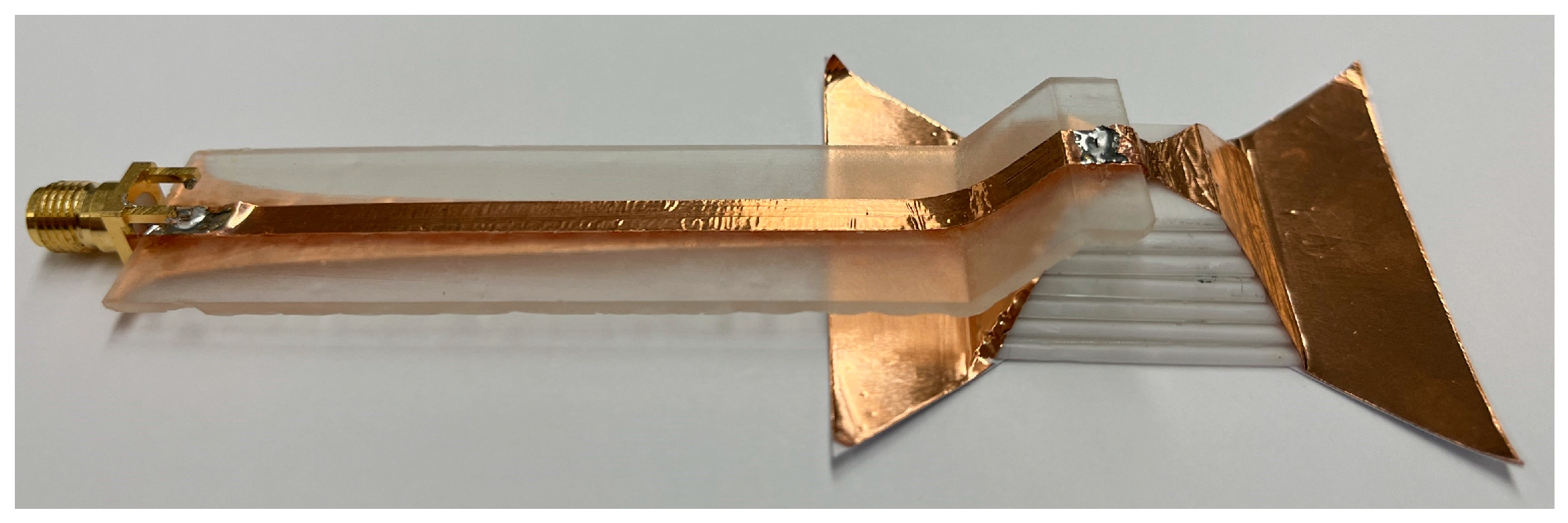
The HCLA was fabricated using a similar procedure to [8]; however, some minor modifications were made. A reduction in plastic and ceramic layers improved the wearability of the antenna without compromising the antenna performance. The copper conductors were also extended from the base of the antenna to reduce the low-frequency cutoff. A single (rather than back-to-back) balun was fabricated using the techniques described in Section 5.3. The output end of balun was then soldered directly to the two conductor arms of the antenna. The final fabricated antenna with the Clear balun is seen in Figure 11.
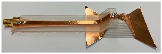
Figure 11.
Fabricated HCLA integrated with the Clear resin balun.
The experimental setup is displayed in Figure 12. Two fabricated antennas integrated with the conformal baluns were placed on either side of ground beef phantom and connected to the FieldFox network analyzer via an SMA launcher. The phantom was contained in a Styrofoam fixture with a fixed thickness of 30 mm. Plastic wrap was used to protect the equipment and was not expected to impact the measurement. The properties of ground beef, however, may have varied due to changes in the temperature, fat content, and/or freshness. In this work, the impact of the balun on the S-parameters of the HCLA will be evaluated. Additional HCLA parameters such as radiation patterns and the specific absorption rate (SAR) can be found in [11].
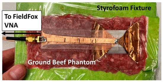
Figure 12.
Experimental setup with the PDMS balun integrated with the HCLA on two-thirds muscle phantom (ground beef).
6.3. Reflection Coefficient Measurement
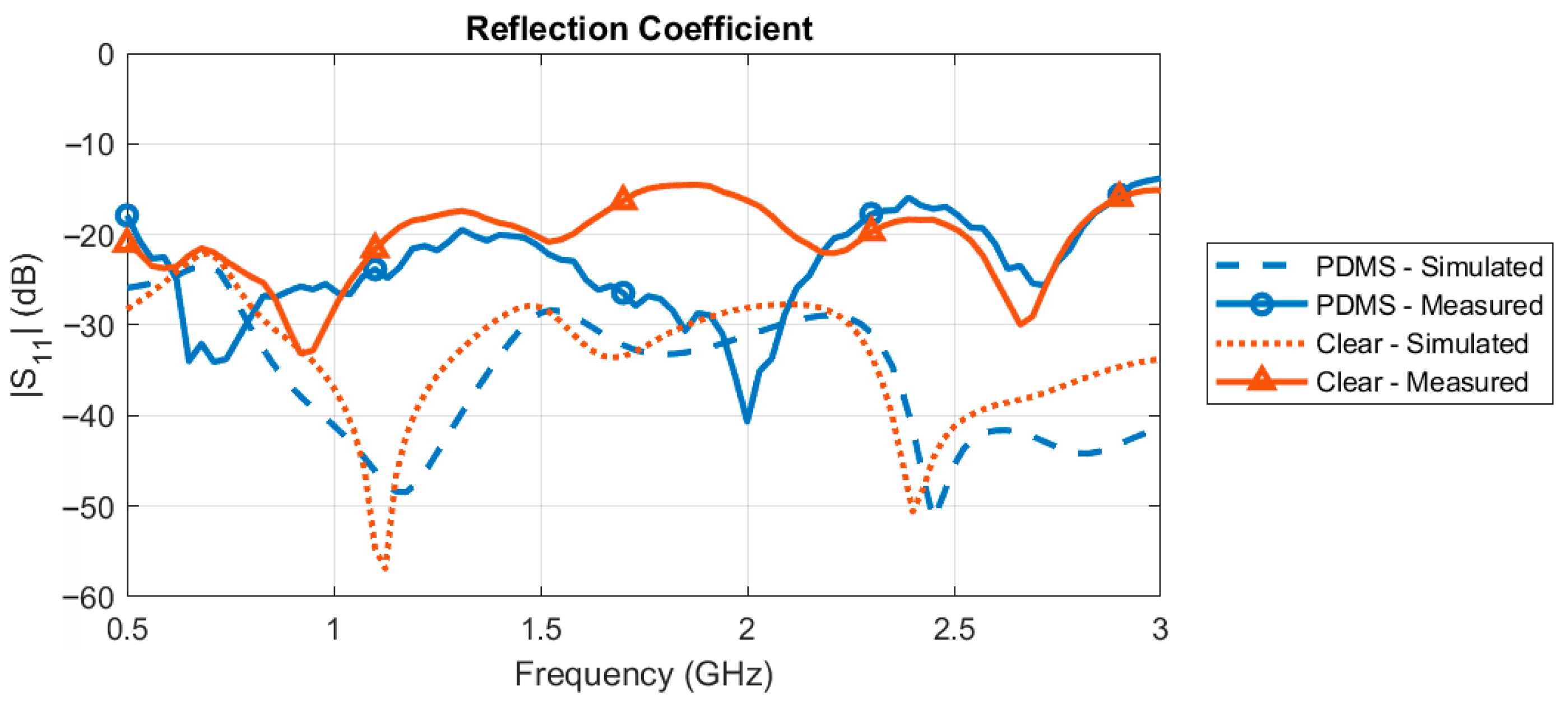
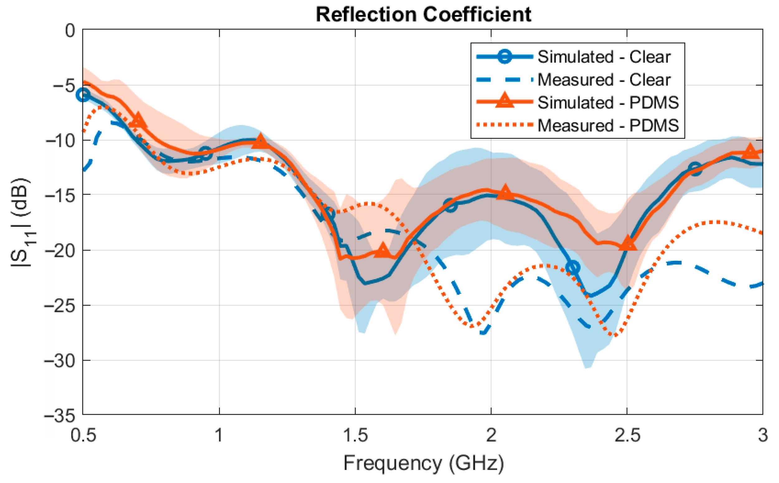
The simulated versus measured reflection coefficient of the HCLA with the balun is displayed in Figure 13, where the shaded region represents the standard deviation between six total measurements. The average measured results matched well to the simulated results, especially in terms of the low-frequency cutoff (i.e., |S11| < −10 dB). The measured low-frequency cutoff for the Clear balun was 680 MHz while the simulated cutoff was 610 MHz. The measured low-frequency cutoff for the PDMS balun was 730 MHz while the simulated cutoff was 650 MHz. Across the bandwidth, the reflection coefficient remained below the target value of −10 dB for both the Clear and PDMS baluns. This ensured that the majority of the power was transmitted through the antenna and into the tissue. The mean standard deviation across the frequencies was 3.39 dB and 2.37 dB for the Clear and PDMS baluns, respectively. Variations between the measurements and differences from the simulation were due to fabrication errors, such as the tolerances of the equipment, the surface roughness of the copper tape, the airgap thickness between the balun, antenna, and phantom, and/or differences in the electromagnetic properties of the ground beef phantom.
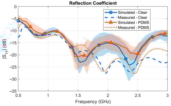
Figure 13.
Simulated vs. measured reflection coefficient of the fabricated antenna with the PDMS and Clear baluns.
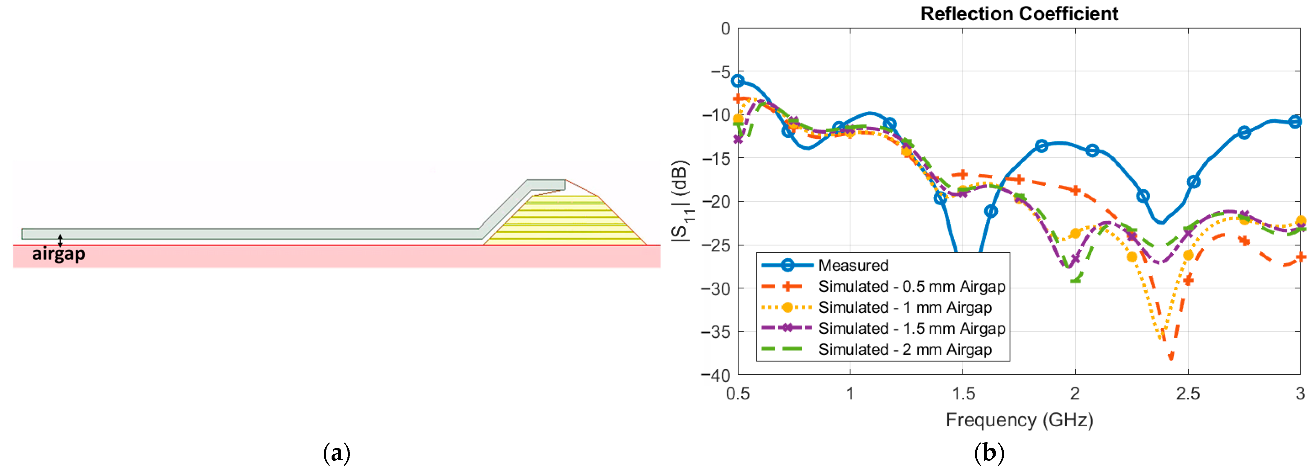
For example, different distances for the airgap between the balun substrate, antenna, and ground beef phantom were simulated. The simulation setup is illustrated in Figure 14a, where the airgap represents the variable distance between the balun substrate and the two-thirds muscle phantom. The airgap also impacts the distance between the balun substrate and the antenna dielectric. The results are demonstrated in Figure 14b. Small variations in the airgap dimensions impact the ripples in the reflection coefficient, especially beyond 1.5 GHz. However, the −10 dB bandwidth stays nearly identical from approximately 750 MHz to 3 GHz. That is, other small variations in the fabrication may impact the ripples of the reflection coefficient at higher frequencies, but the −10 dB operating bandwidth of the antenna will remain the same.
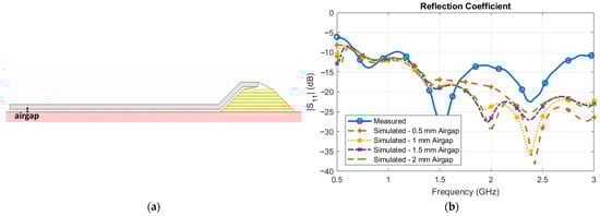
Figure 14.
The (a) simulation setup of the HCLA with different airgap heights between the balun substrate, antenna dielectric, and ground beef phantom and (b) the simulated vs. measured reflection coefficient results.
6.4. Transmission Coefficient
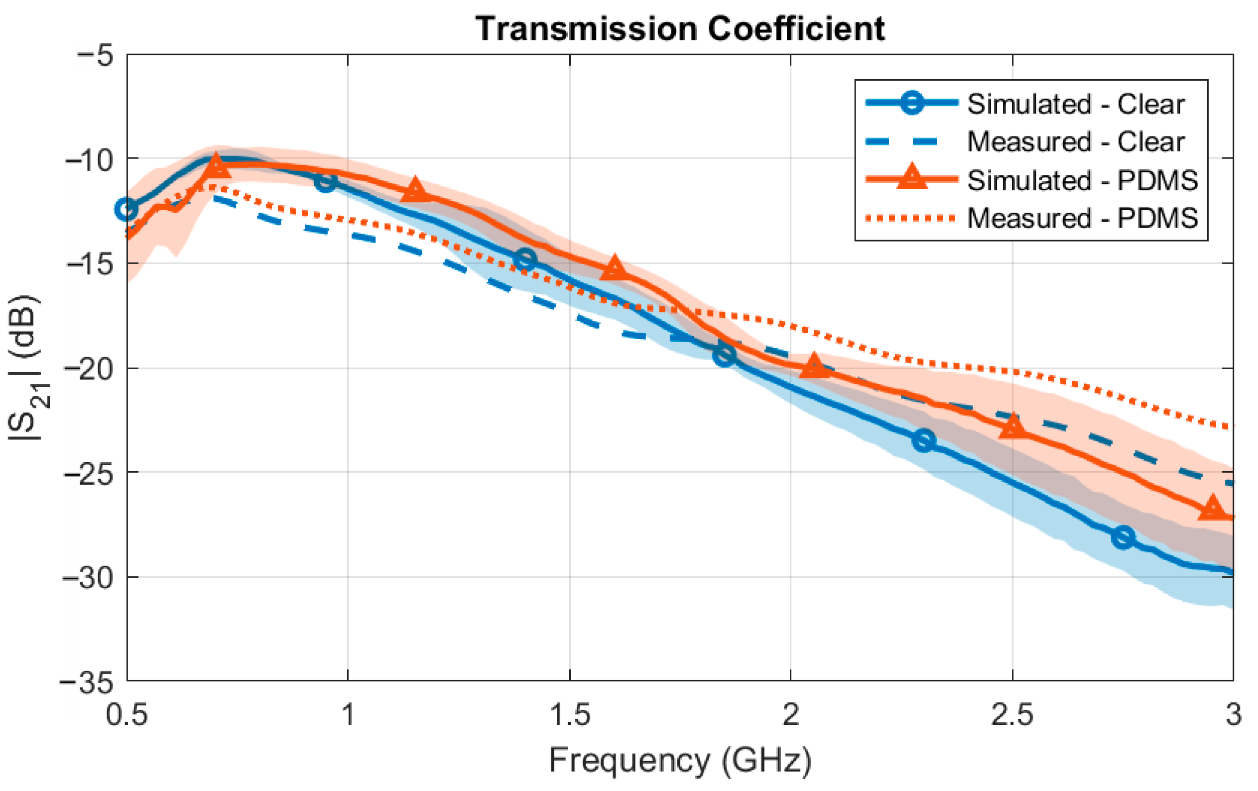
The transmission loss between the two HCLAs was simulated and measured through 30 mm of tissue phantom. The simulated versus measured transmission coefficient is illustrated in Figure 15, where the shaded region represents the standard deviation between the three total measurements. For both the Clear and the PDMS baluns, the measurements matched the simulations well. The mean standard deviation across the frequencies was 1.45 dB and 1.57 dB for the Clear and PDMS baluns, respectively. The difference between the measurements and the variation between the measurement and simulation could be attributed to fabrication errors, misalignment, and/or variations in the properties of the ground beef phantom. Care was taken to ensure that the antennas were aligned; however, small misalignments may have contributed to errors, especially at higher frequencies, where the wavelength is shorter. Variations in the phantom could have also contributed to a higher transmission loss between the antennas. The minimum transmission loss was −10.46 dB at 792 MHz for the PDMS balun, and −9.45 dB at 747 MHz for the Clear balun. As expected, the loss increased with the frequency due to the smaller penetration depth of the electromagnetic waves into the biological tissues.
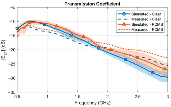
Figure 15.
Simulated vs. measured transmission coefficient of the fabricated antenna with the PDMS and Clear baluns.
7. Discussion
7.1. Wearable Applications
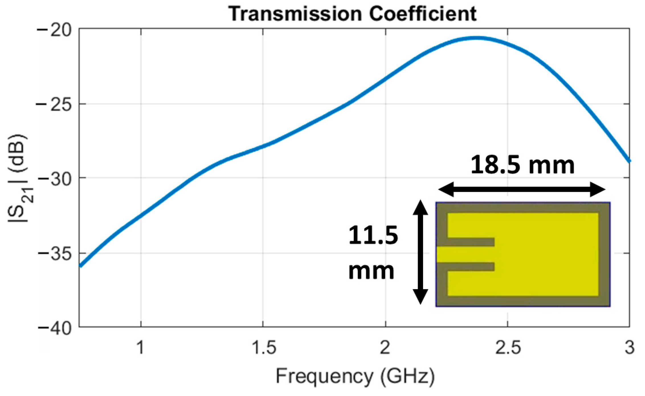
One application for this wearable antenna system is telemetry with a deep-tissue implant antenna. The transmission loss between the HCLA with the conformal balun and a wireless implant antenna was simulated in Ansys HFSS to demonstrate this application. The implant antenna is 11.5 mm by 18.5 mm in size (see inset of Figure 16), and operates at the 2.4 GHz ISM (Industrial, Scientific, and Medical) band with a 360 MHz bandwidth. The implant was placed 3 cm into the two-thirds muscle phantom to represent a deep-tissue implant, and the HCLA was placed on top of the phantom to act as the wearable antenna. The simulated results are illustrated in Figure 16. Notably, the transmission loss is −20.6 dB at 2.4 GHz. Compared to previous work with an HCLA and a commercial off-the-shelf balun [8], the transmission loss improved by approximately 1.2 dB. This work is focused primarily on the balun design and implementation. Measurements for the antenna itself can be found in [8], and the improved balun reported herewith is not expected to significantly alter its radiation performance. Future work will include the implementation and integration of the HCLA in applications such as telemetry.

Figure 16.
Simulated transmission loss of the HCLA to a 2.4 GHz implantable antenna.
7.2. Application to Other Antennas
The proposed balun design, while analyzed extensively with the HCLA as an example, is not limited to the HCLA, and can be applied to other diverse wearable and conformal antennas. For example, in [13], an ultrawideband bowtie antenna fed with a microstrip-to-parallel-strip-line balun was presented for microwave imaging applications. The balun was integrated in the perpendicular configuration (but the substrate could have easily been conformed to the bowtie antenna substrate via AM). The dimensions of the conformal balun would be similar to the HCLA balun to perform imaging from 1 to 6 GHz. In this case, a conformal balun would save 48 mm in all directions, which is particularly useful for portable microwave imaging applications (e.g., stroke detection).
In general, the balun can be easily adjusted for different frequency ranges. The length of the balun is dependent on the wavelength of the lowest operational frequency. To reach lower frequencies, the length of the balun should be larger than 80 mm, while, if lower frequencies are not required, the length of the balun could be smaller than 80 mm.
The substrate materials are also not limited to those characterized here. There are a myriad of materials and printers available for additive manufacturing applications. The materials, however, would need to be characterized in terms of their electromagnetic properties (i.e., εr and tanδ) before implementation so that the correct microstrip and parallel strip line widths can be calculated for the balun. As a non-limiting example, Rogers has recently released a printable dielectric called Radix that is designed specifically for low loss through millimeter-wave frequencies [31]. This material could improve the insertion loss of the balun; however, the material itself and the required printer are very costly, which inhibits its use compared to other widely available, cheaper systems. In terms of the mechanical properties, polymers with various stretching and bending capabilities could be explored to enhance the wearability and conformality for applications in different regions of the body. Solid resins are better suited for applications where mechanical stability is important.
Lastly, different types of additive manufacturing can be considered. In this work, SLA printing techniques were used. SLA printing involves using a light source to solidify liquid resin into a 3D object, and results in smoother surface finishes and tighter tolerances. Fused deposition modeling (FDM) employs a heated extruder to deposit filament in layers to create a 3D object, which is generally quicker but results in parts with visible, rough layers. Lastly, selective laser sintering (SLS) uses a laser to fuse small particles of polymer powder. SLS parts have strong mechanical characteristics, but a slightly rough surface finish and more limited material options. Surface roughness, inherent to FDM or SLS printing, may add additional losses to the balun. There is a compromise to be made between the materials, resolution, surface finish, cost, and ease of use [32].
8. Conclusions
We overcame previous balun limitations by presenting an additively manufactured microstrip balun design for the conformal feeding of wearable, balanced antennas. We have demonstrated balun integration and performance on the High-Contrast Low-Loss Antenna (HCLA); however, the design method is flexible, which allows for custom implementation for a myriad of antennas. Simulations and measurements of the balun integrated with the HCLA verified that the conformal configuration could be used with minimal impacts on the antenna performance. With this new balun, the HCLA demonstrates a superior reflection coefficient (|S11| < −15 dB) and insertion loss (|S21| < −2 dB) performance than with the previous commercial off-the-shelf balun. Importantly, the size of the system has been reduced from 120 mm × 50.5 mm × 4.2 mm to 80 mm × 20 mm × 1.55 mm, and conformality has been improved, so that the antenna can be implemented in wearable applications. Additionally, the electromagnetic characterization of the Formlabs resins was performed from 500 MHz to 3 GHz for the first time. In summary, the Clear and Rigid resins were found to have low loss tangents, which are optimal for RF applications, while the Elastic 50A and Flexible 80A have high loss tangents, which prohibit their use.
Overall, this flexible, three-dimensional balun design brings forward limitless opportunities for balanced antenna applications, both wearable and general purpose. Future work will focus on transitioning the conductor from tape to copper (using deposition techniques), conductive inks, or conductive threads. Recently developed low-loss resins such as Rogers Radix will be explored to improve the insertion loss. Finally, the HCLA with the improved balun will be implemented in telemetry, imaging, or sensing applications.
Author Contributions
Conceptualization, methodology, resources, investigation, formal analysis, and funding acquisition, A.R. and A.K.; software, validation, visualization, data curation, and writing—original draft preparation, A.R.; writing—review and editing, supervision, and project administration, A.K. All authors have read and agreed to the published version of the manuscript.
Funding
This work was supported by a NASA Space Technology Graduate Research Opportunities Award under grant 80NSSC21K1261, as well as by the National Science Foundation (NSF) award no. 2244882.
Data Availability Statement
The original contributions presented in this study are included in the article.
Conflicts of Interest
The authors declare no conflicts of interest.
References
- Kumar, S.; Moloudian, G.; Simorangkir, R.B.V.B.; Gawade, D.R.; O’Flynn, B.; Buckley, J.L. Sub-GHz wrist-worn antennas for wireless sensing applications: A review. IEEE Open J. Antennas Propag. 2024, 5, 1258–1281. [Google Scholar] [CrossRef]
- Mahmood, S.N.; Ishak, A.J.; Ismail, A.; Soh, A.C.; Zakaria, Z.; Alani, S. ON-OFF body ultra-wideband (UWB) antenna for wireless body area networks (WBAN): A review. IEEE Access 2020, 8, 150844–150863. [Google Scholar] [CrossRef]
- Kiourti, A.; Costa, J.R.; Fernandes, C.A.; Santiago, A.G.; Nikita, K.S. Miniature implantable antennas for bio-medical telemetry: From simulation to realization. IEEE Trans. Biomed. Eng. 2012, 59, 3140–3147. [Google Scholar] [CrossRef]
- Tisdale, K.; Bringer, A.; Kiourti, A. A core body temperature retrieval method for microwave radiometry when tissue permittivity is unknown. IEEE J. Electromagn. RF Microw. Med. Biol. 2022, 6, 470–476. [Google Scholar] [CrossRef] [PubMed]
- Alqadami, A.S.M.; Zamani, A.; Trakic, A.; Abbosh, A. Flexible electromagnetic cap for three-dimensional electromagnetic head imaging. IEEE Trans. Biomed. Eng. 2021, 68, 2880–2891. [Google Scholar] [CrossRef] [PubMed]
- Paracha, K.N.; Rahim, S.K.A.; Soh, P.J.; Khalily, M. Wearable antennas: A review of materials, structures, and innovative features for autonomous communication and sensing. IEEE Access 2019, 7, 56694–56712. [Google Scholar] [CrossRef]
- Ali, U.; Ullah, S.; Kamal, B.; Matekovits, L.; Altaf, A. Design, analysis and applications of wearable antennas: A review. IEEE Access 2023, 11, 14458–14486. [Google Scholar] [CrossRef]
- Rice, A.; Kiourti, A. High-contrast low-loss antenna: A novel antenna for efficient into-body radiation. IEEE Trans. Antennas Propag. 2022, 70, 10132–10140. [Google Scholar] [CrossRef] [PubMed]
- Acti, T.; Chauraya, A.; Zhang, S.; Whittow, W.G.; Seager, R.; Vardaxoglou, J.C.; Dias, T. Embroidered wire dipole antennas using novel copper yarns. IEEE Antennas Wirel. Propaga-Tion Lett. 2015, 14, 638–641. [Google Scholar] [CrossRef]
- Alharbi, S.; Chaudhari, S.; Inshaar, A.; Shah, H.; Zou, C.; Harne, R.L.; Kiourti, A. E-textile origami dipole antennas with graded embroidery for adaptive RF performance. IEEE Antennas Wirel. Propag. Lett. 2018, 17, 2218–2222. [Google Scholar] [CrossRef]
- Zhong, J.; Lee, C.W.; Papantonis, D.; Kiourti, A.; Volakis, J.L. Body-worn 30:1 bandwidth tightly coupled di-pole array on conductive textiles. IEEE Antennas Wirel. Propag. Lett. 2018, 17, 723–726. [Google Scholar] [CrossRef]
- Lee, H.; Tentzeris, M.M.; Geiger, J. Flexible spiral antenna with microstrip tapered infinite balun for wearable applications. In Proceedings of the 2012 IEEE International Symposium on Antennas and Propagation, Chicago, IL, USA, 8–14 July 2012; pp. 1–2. [Google Scholar] [CrossRef]
- Fiser, O.; Hruby, V.; Vrba, J.; Drizdal, T.; Tesarik, J.; Vrba, J., Jr.; Vrba, D. UWB bowtie antenna for medical microwave imaging applications. IEEE Trans. Antennas Propag. 2022, 70, 5357–5372. [Google Scholar] [CrossRef]
- Chen, S.J.; Fumeaux, C.; Ranasinghe, D.C.; Kaufmann, T. Paired snap-on buttons connections for balanced antennas in wearable systems. IEEE Antennas Wirel. Propag. Lett. 2015, 14, 1498–1501. [Google Scholar] [CrossRef]
- Qu, S.-W.; Li, J.-L.; Xue, Q.; Chan, C.H.; Li, S. Wideband and Unidirectional Cavity-Backed Folded Triangular Bowtie Antenna. IEEE Trans. Antennas Propag. 2009, 57, 1259–1263. [Google Scholar] [CrossRef]
- Cheng, L.; Wen, H.; Liu, Y.; Jiang, Y.; Zhou, Z.; Zhang, J.; Zhang, G.; Mao, H. Study on balun miniaturized flexible archimedes spiral antenna for partial discharge detection. In Proceedings of the 2022 IEEE 2nd International Conference on Electronic Technology, Communication and Information (ICETCI), Changchun, China, 27–29 May 2022; IEEE: Piscataway, NJ, USA, 2022; pp. 912–917. [Google Scholar] [CrossRef]
- Woo, D.S.; Cho, Y.-K.; Kim, K.W. Balance analysis of microstrip-to-CPS baluns and its effects on broadband antenna performance. Int. J. Antennas Propag. 2013, 2013, 1–9. [Google Scholar] [CrossRef]
- Durgun, A.C.; Balanis, C.A.; Birtcher, C.R.; Allee, D.R. Design, simulation, fabrication and testing of flexible bow-tie antennas. IEEE Trans. Antennas Propag. 2011, 59, 4425–4435. [Google Scholar] [CrossRef]
- Yogendrappa, M. FR4 Material for PCB Fabrication. Sierra Circuits. Available online: https://www.protoexpress.com/blog/why-fr4-material-in-pcb-fabrication/ (accessed on 7 May 2024).
- TMM® 10 Laminates. Available online: https://www.rogerscorp.com/advanced-electronics-solutions/tmm-laminates/tmm-10-laminates (accessed on 30 January 2024).
- Materials Library. Available online: https://formlabs-media.formlabs.com/filer_public/ac/89/ac8963db-f54a-4cac-8fe9-fb740a7b06f1/formlabs-materials-library.pdf (accessed on 2 January 2025).
- Palazzi, V.; Su, W.; Bahr, R.; Bittolo-Bon, S.; Alimenti, F.; Mezzanotte, P.; Valentini, L.; Tentzeris, M.M.; Roselli, L. 3-D-printing-based selective-ink-deposition technique enabling complex antenna and RF struc-tures for 5G applications up to 6 GHz. IEEE Trans. Compon., Packag. Manufact. Technol. 2019, 9, 1434–1447. [Google Scholar] [CrossRef]
- Battistini, G.; Paolini, G.; Masotti, D.; Costanzo, A. 3-D etching techniques for low-cost wearable microwave devices in grounded coplanar waveguide. In Proceedings of the 2022 IEEE MTT-S International Microwave Biomedical Conference (IM-BioC), Suzhou, China, 16–18 May 2022; IEEE: Piscataway, NJ, USA, 2022; pp. 63–65. [Google Scholar] [CrossRef]
- Keysight. N1501A Dielectric Probe Kit 10 MHz to 50 GHz|Keysight. Available online: https://www.keysight.com/us/en/assets/7018-04631/technical-overviews/5992-0264.pdf (accessed on 16 February 2024).
- Cresson, P.-Y.; Orlic, Y.; Legier, J.F.; Paleczny, E.; Dubois, L.; Tiercelin, N.; Coquet, P.; Pernod, P.; Lasri, T. 1 to 220 GHz complex permittivity behavior of flexible polydimethylsiloxane substrate. IEEE Microw. Wirel. Compon. Lett. 2014, 24, 278–280. [Google Scholar] [CrossRef]
- Hammed, R.T. Compact marchand balun circuit for UWB application. AEU Int. J. Electron. Commun. 2015, 69, 851–855. [Google Scholar] [CrossRef]
- Pozar, D. Microwave Engineering, 4th ed.; Wiley: Hoboken, NJ, USA, 2012. [Google Scholar]
- Ansys HFSS|3D High Frequency Simulation Software. Available online: https://www.ansys.com/products/electronics/ansys-hfss (accessed on 4 November 2022).
- Form 2: Affordable Desktop SLA 3D Printer. Formlabs. Available online: https://formlabs.com/3d-printers/form-2/ (accessed on 15 May 2024).
- Nguyen, H.-D.; Coupez, J.P.; Castel, V.; Person, C.; Delattre, A.; Crowther-Alwyn, L.; Borel, P. RF characterization of flexible substrates for new conformable antenna systems. In Proceedings of the 2016 10th European Conference on Antennas and Propagation (EuCAP), Davos, Switzerland, 10–15 April 2016; pp. 1–5. [Google Scholar] [CrossRef]
- RadixTM Printable Dielectric. Available online: https://www.rogerscorp.com/advanced-electronics-solutions/radix-printable-dielectric (accessed on 6 September 2024).
- FDM vs. SLA vs. SLS: 3D Printing Technology Comparison. Formlabs. Available online: https://formlabs.com/blog/fdm-vs-sla-vs-sls-how-to-choose-the-right-3d-printing-technology/ (accessed on 30 September 2024).


Disclaimer/Publisher’s Note: The statements, opinions and data contained in all publications are solely those of the individual author(s) and contributor(s) and not of MDPI and/or the editor(s). MDPI and/or the editor(s) disclaim responsibility for any injury to people or property resulting from any ideas, methods, instructions or products referred to in the content. |
© 2025 by the authors. Licensee MDPI, Basel, Switzerland. This article is an open access article distributed under the terms and conditions of the Creative Commons Attribution (CC BY) license (https://creativecommons.org/licenses/by/4.0/).