Abstract
The windup phenomenon occurs and results in performance degradation while the designed positioning controller output makes actuators saturated. This study presents significant and effective anti-windup controllers for performance improvement and comparison of the position tracking. To address real-world industrial scenarios, the trajectory with a T-curve velocity profile is planned to regulate hardware limitations and maintain efficiency throughout the control process. At first, the dynamic model of an inertia load for a servo control system is established using Newton’s law of motion. Then, anti-windup controllers are designed and implemented based on basic PID controllers. The conducted simulations validate its effectiveness and feasibility. Finally, experimental results demonstrate that the proposed algorithms achieve smaller overshoot and faster settling time under input saturations when executing specific paths on the X-Y platform, even though the given control commands change. It is verified that the proposed approaches can, indeed, effectively mitigate the windup phenomenon, leading to improved positioning accuracy in industrial applications.
1. Introduction
Due to the rapid development of robotic and servo systems, control systems have adopted faster and more precise position or speed regulation for good qualities and high efficiency. In electric vehicle (EVs) [1,2], hydraulic systems [3], and pneumatic systems [4,5], modern control techniques like robust control [6], adaptive control [7,8,9], and fuzzy control [10,11] have been applied to enhance system performance. However, to achieve high-performance control and fast response time, controllers always suffer from actuator limitations [12], such as rated torques or speed constraints. This means that the output of actual devices may be suppressed, resulting in lower-than-expected performance. The existing issue leading to this performance degradation is called a wind-up problem [13].
Considering that the control systems always need to operate in wide range conditions and different environments, the control inputs may reach the actuator limits. In addition, the higher accuracy requirements and faster response time needed in the control system mean that even small changes in the controller input may have a significant impact on the operation system. The result is that the feedback loop does not work very well, and the closed-loop system becomes an open-loop system as actuators remain at its limits regardless of the process output. One of the main reasons is that the controller’s integral component is imperfectly designed. It may continue to integrate error signals while control inputs meet saturation. This causes the integral term to grow excessively large. This phenomenon is known as integral windup or simply windup, where the error has an opposite sign with the control input during a calibration period before the system is normally operated. Therefore, the integral action in control systems may produce extreme responses if an actuator input becomes saturated or if the process input changes unexpectedly [14]. This issue must be tackled as a priority.
To overcome this difficulty and phenomenon, various anti-windup techniques have been proposed in some studies to facilitate better control performance. A few decades ago, the control law designed by Wittenmark et al. [15] contained an explicit observer ensuring that the output remained stable under a bounded input. Markaroglu et al. [16] reviewed the tuning of the tracking time parameter in the back-calculation anti-windup scheme. Further, Yang et al. [17] surveyed a new anti-windup technique for the PI structure which relied on the back-calculation method. The proposed novel technique eliminated the problem caused by the fixed back calculation gain in the traditional anti-windup scheme and prevented a large overshoot or untimely saturation withdrawing from the Permanent Magnet Synchronous Motor (PMSM) servo system. In [18], Espina et al. comprehensively investigated the anti-windup strategies by addressing the undesired windup phenomenon through designed current and speed controllers for the field-oriented control (FOC) of PMSM systems. Recently, the dynamic anti-windup compensators for time-varying or nonlinear systems have also been thoroughly discussed and have solved the anti-windup problem by means of the solvability LMIs and neural networks (NN) [19,20,21]. Therefore, the typical way to solve the wind-up problem is by automatically adjusting the controller, ignoring actuator saturation, and subsequently adding compensators to prevent the occurrence of wind-up conditions. In summary, although numerous methods have been proposed to address the saturation problem, there remains a significant gap in research regarding the comparative analysis of their performance in practical applications.
In this work, we employ two anti-windup strategies for an X-Y platform to improve the adverse effects of the wind-up problem and further enhance the control precision performance for comparison. Although the aforementioned approaches have demonstrated promising results, certain studies remain confined to simulations, failing to consider the practical limitations and constraints of real actuators. The main contributions are summarized as (1) the framework of the X-Y platform is characterized and analyzed by introducing the dynamic motion equation of the servo motor. Considering the actuator saturations, external disturbances, and load variations of the servo motor, the corresponding state-space representation is obtained. (2) Positioning controllers based on two anti-windup algorithms is proposed for fast and precise tracking. Additionally, simulation analysis is conducted using the state-space model of the servo motor to verify that the system can achieve high-precision and fast trajectory tracking despite saturations happening. (3) By using the high-resolution sensors in the servo motors, the practical experiments of the physical X-Y platform are executed. In this process, both trajectory planning in real-world scenarios and the proposed anti-windup positioning controllers based on basic PID control are integrated with the hardware. It turns out that the effectiveness and feasibility of the proposed approach have been validated and demonstrate performance of the planned T-curve velocity profile as expected through the corresponding simulation and experiments.
2. Dynamics of an X-Y Platform and Problem Statement
2.1. Dynamics of an X-Y Platform
This study explores the dynamic system of an X-Y platform where servo motors provide direct actuations to the inertia-based loads. The illustration of the servo motion control system is shown in Figure 1. In this system, a velocity control mode is applied to the servo driver which receives the control velocity signal from the motion controller. Since the current loop responds much faster than the relevant frequency, its dynamic effect is not included in the modeling process. Hence, the dynamics of the inertia load can be described as [22]
where denotes the motor moving displacement; and represent the moment of inertia and the viscous damping coefficient, respectively; represents the control input, and is the external disturbance model dynamics. Further, taking an input saturation into account, the servo motor dynamics [23] can be rewritten in a state-space representation form of (1) as follows:
where and , respectively, represent the state which consists of the motor displacement and its time derivative, measurement output, control input, input disturbance which usually refers to external forces like frictional forces that interfere with the normal operation of the system, and the saturation function for the control input constrained by the system’s physical limits. The element of the corresponding matrix represents the effect of damping on the system, and denotes the effect of the control input on the acceleration.
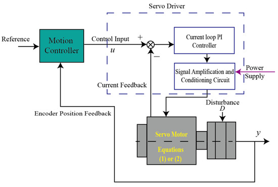
Figure 1.
Illustration of a typical servo system.
2.2. Problem Statement
The primary control objective of this study is to develop streamlined and efficient methodologies for a PID controller applied to the X-Y platform, with the goal of minimizing tracking errors when the servo motors encounter unforeseen disturbances and input saturations . Due to possible integration saturation, anti-windup algorithms based on basic PID controllers in the motion controller shown in Figure 1 are proposed here to mitigate the effects including windup and disturbance influences, and then upgrade the control performance.
3. PID Positioning Controller with Anti-Windup Algorithms Design
3.1. PID Controller Design Based on the Standard Back-Calculation Algorithm
The control law is initially derived from the standard back-calculation principle for a desired set-point tracking. The continuous system with sampling time is denoted as and its discretization form based on , , , matrices within the sampling interval in (2) is described as follows:
where The following basic PID positioning controller [24] can be represented as
where is the proportional gain; is the derivative gain; is integral gain; and denotes the filter parameter of the derivative part. The discretized form (5) can be obtained from its equivalent continuous-time counterpart (4) as
where is the sampling period. Using the PID form displayed in (5), the discretized control input can be expressed as
where , and are, respectively, proportional, integral, and derivation control terms. These three terms can be represented as
where and is a designed reference signal. Assume that the control input is an input voltage limited by a device-saturation, and the relationship can be expressed as
where denotes a limit value of the control input, is a signum function which determines the sign of the control input, is the computed control input. The saturation may occur due to the PID controller with the integral action. Therefore, an anti-windup scheme called by the back-calculation algorithm is proposed below
where is the back-calculation integral control term; is a back-calculation gain; and . By replacing the integral control term in (6) with in (11), the new control input with the back-calculation algorithm is yielded as
The overall control block diagram is shown in Figure 2.
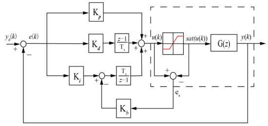
Figure 2.
Block diagram of a basic PID controller with the back-calculation.
The characteristic of this anti-windup approach is that a gain based on the feedback loop is designed to reduce the effect of the integral windup. The process explanations of the Algorithm 1 are as follows:
| Algorithm 1. Back-calculation anti-windup algorithm |
| Input: -The design of the corresponding control parameter should consider the saturation degree. -The system’s limited input . -The calculated control input . Output: adjusted integral operation to mitigate windup. if : 1. Activate the anti-windup mechanism for the integral operation. 2. Calculate the deviation: . 3. Scale the deviation by : Correction: . 4. Apply the correction as feedback to the integral term to reduce windup. else Maintain the normal operation of the integral control. end if |
To verify the effectiveness of this control scheme which is applied to the servo motor system, the corresponding simulation is conducted. The system parameters are obtained using one of two servo motors (i.e., with a rated power of 400 W) in the experimental setup as the simulation model, and the parameters are obtained via a system identification technique. The system parameters , in (2) are used, with an input voltage constraint of and the control parameters , , are assigned. The PID control gains , , are chosen. The reference signal is a step input, and total simulation time is 15s. The step response is shown in the following Figure 3. The motor demonstrated a rapid rise time of 0.96 s, when larger reference values are set and there are significant overshoots of 1.9%, primarily due to the wind-up phenomenon. Therefore, the back-calculation scheme is added to the control system that reduces the overshoot and has a minimal oscillation. The remarkable results demonstrate a substantial reduction in overshoot from 1.9% to 0.29% for the servo motor system. As a result, the back-calculation approach can, indeed, improve the wind-up performance.
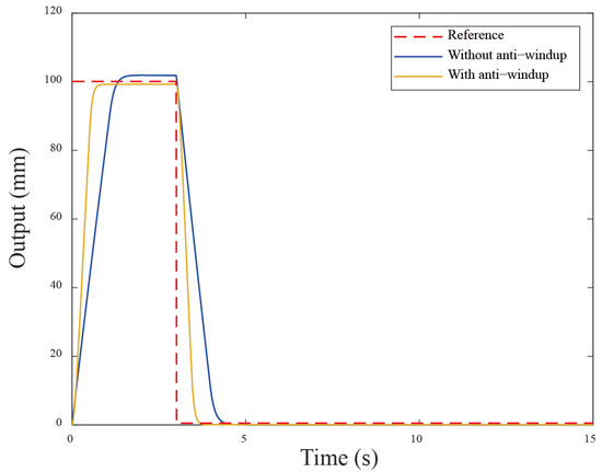
Figure 3.
The simulation results using the back-calculation algorithm.
3.2. PID Controller Design Based on the Standard Clamping Algorithm
Another anti-windup method known as the clamping algorithm is introduced for performance comparison. The clamping algorithm here directly controls the integral output of a basic PID controller. Its key feature is that it monitors if the computed control input reaches the system’s limits. Once these limits are reached, the integral operation is terminated to prevent the windup condition happening using the switch . The following Figure 4 illustrates the control block diagram of basic PID controller with the clamping algorithm.
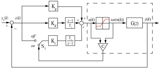
Figure 4.
Block diagram of basic PID controller with the clamping.
In Figure 4, a comparator is positioned between the computed control input and the limit value . This comparator determines whether the computed control input exceeds the system’s limits. The output of the comparator can be expressed as
Through the mechanism of the comparator , the integral part can decide the state of the switch , turning the integral operation on when and off when . Hence, the integral term of the control input in the clamping form is represented as
By using (14) to replace the term of (6), the new control input is given by
The anti-windup mechanism ensures that, when the control signal exceeds the allowed limit, the system pauses the integral part to prevent rapid error accumulation. Next, the proposed anti-windup algorithms compared to without the anti-windup approach are simulated and compared in Figure 5. From the responses of Figure 5, the anti-windup method demonstrates better performance compared to that without anti-windup. In addition, it is observed that large overshoot occurs when motors receive a larger reference (i.e., a dramatic step change). The possible solution is that the control system needs to impose limits to follow the command signal, resulting in nonlinear effects when reaching the input limit. In comparison with the back-calculation method, the clamping algorithm operates similarly to a bang-bang control, manipulating the integral action to avoid the windup occurrence. The response shows reduced overshoot from 1.9% to −0.47%. Additionally, the corresponding rise time has obvious improvement from . The control system has a different extent optimization in these two anti-windup schemes. Comparing two cases, we can see that using the previous back-calculation method demonstrates better performance than using the clamping algorithm. This is because the clamping algorithm calculates the control input in a way that causes the integral part to stop discretely during the control process. The corresponding simulation control inputs are shown in Figure 6.
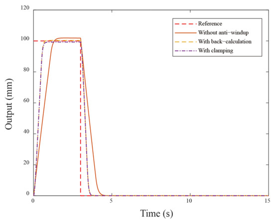
Figure 5.
The simulation results under different anti-windup algorithms.
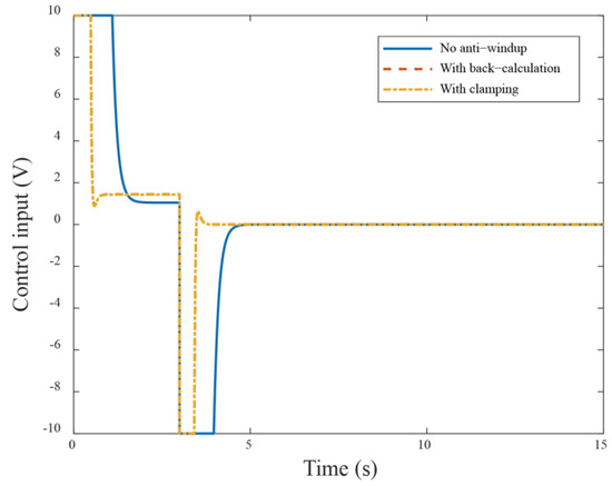
Figure 6.
The control input responses in the simulation under different anti-windup algorithms.
4. Experimental Results and Discussions
According to the above simulation results obtained from the servo motor dynamics model, the practical implementation will demonstrate the actual performance of the two anti-windup algorithms in the experiement similar to ones in the simulation. An X-Y platform manufactured by TECO Inc., Taipei, Taiwan is used to experimentally validate the effectiveness of the proposed anti-windup algorithms. The experimental setup of the X-Y platform is shown in Figure 7. In this configuration, two servo motors (JSMA-PUC01) and (TSX06401C-3N33), along with the servo driver (JSDG2), make up the X-Y platform. In addition, the rotary encoders included in the servo motors are 17-bit incremental encoders capable of achieving a positioning resolution of up to 0.4 mm, and the communication of each component is established based on the PCIe protocol. The nominal values of the moment of inertia J and the damping coefficient B are and for the x–axis motor, and and for the y–axis motor.
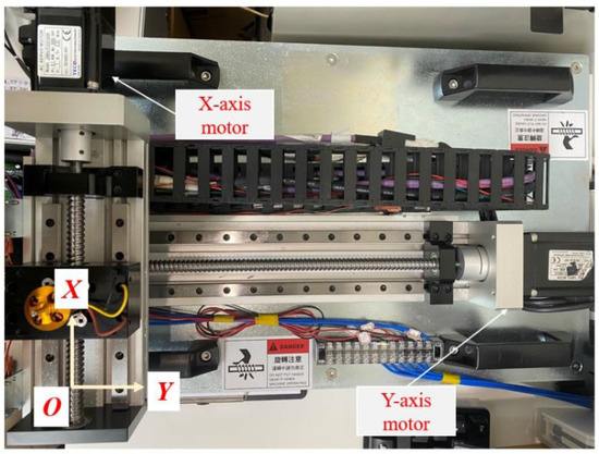
Figure 7.
The experimental X-Y platform based on the servo motor system.
The servo system receives motion controller commands (e.g., voltage) and tracks the specified trajectory. The used control parameters are shown in Table 1 and adjusted to better control performance based on practical experiments. The experimental results demonstrate how the applied anti-windup algorithms are effectively operated in nonlinear regions while maintaining their stability and enhancing the control performance, particularly in the presence of input saturations. Although other uncertainties are present, they can be tackled by the basic PID controller. To compare the performance differences between the traditional control methods (i.e., PID control) and the basic PID with anti-windup methods under saturation conditions, specific reference trajectories are designed. In motion control applications, trajectory planning plays a crucial role in system performance evaluation. The trapezoidal velocity profile is the most popular method to produce the path for motion control due to its high efficiency and quick implementation. This type of trajectory planning is also known as a T-curve which is widely used because they provide smooth acceleration and deceleration, reducing mechanical stress on the system. First, the Bézier motion curve is designed to verify the effectiveness of the proposed control scheme. The Bézier curve is a parametric-based method, offering smoother transitions and greater flexibility in trajectory design. To produce a smooth trajectory from the planned Bézier curve, careful parameter selection is crucial. Figure 8 depicts the designed curve used in this experiment. The designed time-dependent path functions and fit the Bézier curve, and are expressed as follows:
and the corresponding velocities are given by

Table 1.
The control parameters in the experiment.
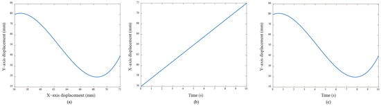
Figure 8.
(a) The Bézier curve designed for the experiment; (b,c) are, respectively, the independent motion commands for both servo motors.
Further, a quadrilateral trajectory is also designed based on the T-curve velocity profile. Figure 9 displays the command signal for the quadrilateral trajectory used in this experiment. The trajectory begins at the bottom left corner , proceeds to , then to , continues to , and finally returns to .
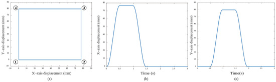
Figure 9.
(a) The quadrilateral curve designed for the experiment; (b) and (c) are the independent motion commands for both servo motors, respectively.
The maximum velocity and acceleration of the T-curve profile are set as specific values during entire process as follows:
- Physical limitations:
In the Bézier curve case, the y–axis servo response is the main focus, as the x–axis servo response is trivial due to the absence of a saturation situation. Figure 10a displays the transient response of the X-Y platform with a significant overshoot of 18% without anti-windup algorithms. After applying the anti-windup algorithms, the overshoots shown in Figure 10b,c are reduced to 2.16% and 4.59% for the back-calculation and clamping algorithms, respectively. Moreover, Figure 10 displays the path-tracking response based on a situation without anti-windup, back-calculation, and clamping algorithms. Experimental results reveal that, without the anti-windup algorithm, significant overshoots are larger, as shown in Figure 10a and Figure 11a: 8% for the x–axis servo and 34.22% for the y–axis servo. This clearly demonstrates the occurrence of the windup phenomenon, and the proposed anti-windup algorithms can substantially improve the overshoot and obtain superior performance. The corresponding performance indices are presented in Table 2.
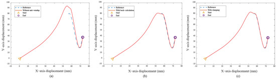
Figure 10.
Experimental results for the Bézier curve: (a) without anti-windup, (b) with back-calculation algorithm, and (c) with clamping algorithm.
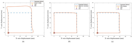
Figure 11.
Experimental results for the quadrilateral curve: (a) without anti-windup, (b) with back-calculation algorithm, and (c) with clamping algorithm.
Table 2.
The overshoot comparison of different anti-windup algorithms in Bézier and quadrilateral curve.
These results show that anti-windup algorithms obtain a different extent progress in the experiment, namely, the performance using the back-calculation is generally better than one using the clamping since the designed parameter can be adjusted through the experimental operation to obtain a fast and stable response in back-calculation algorithm. On the other hand, the clamping control allows the integral component to remain hidden, approximating PD control during the saturation period, which results in a larger overshoot for the X-Y platform system. Figure 12 and Figure 13 show the tracking error responses and the range of the accuracy values without any anti-windup algorithms in quadrilateral curve, which are and for each motor, and using the back-calculation algorithm, and and using the clamping algorithms. The maximum steady-state error is without anti-windup, in the back-calculation algorithm, and in the clamping algorithms for the Bézier curve. The corresponding velocity responses of each axis are shown in Figure 14 and Figure 15. We all know that the control system’s ability to follow the specific path, based on the previously designed T-curve velocity profile, depends on parameter settings, resulting in the system to experience a greater load. The results show a larger dynamic error between the planned velocity and the control system’s response when anti-windup algorithms are not applied. However, after applying the proposed algorithms, the velocity response is able to more closely match the planned velocity in quadrilateral curve. In the tracking of the Bézier curve, it also demonstrates that the velocity responses are greatly improved after applying the anti-windup algorithm. Figure 16 and Figure 17, respectively, display their corresponding control inputs in different designed motion paths. It can be observed that, without the anti-windup algorithm, the control system experiences varying degrees of saturation issues, resulting in a significant increase in both overshoot and tracking error during the saturation period. The back-calculation method presents the highest level of stability and the smallest tracking error, while the clamping method offers substantial control performance. The comparison of experimental and simulation results further underscores the advantages of the back-calculation method in improving system performance. Specifically, the overshoot is substantially reduced: from 1.9% to −0.47% in the simulation, from 18% to 2.16% (y–axis) in the experimental results based on the Bézier curve, and from 8% to 0.97% (x–axis) for the quadrilateral path in the experimental results. Despite significant variations in the input reference signal, the results confirm that the back-calculation approach is highly effective in enhancing the overall control performance of the X-Y platform.
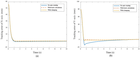
Figure 12.
The tracking error responses under different cases (a) X–axis (b) Y–axis in Bézier curve.
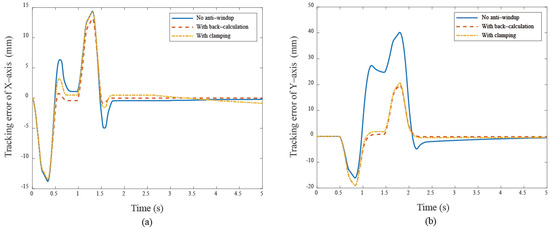
Figure 13.
The tracking error responses under different cases (a) X–axis (b) Y–axis in quadrilateral curve.
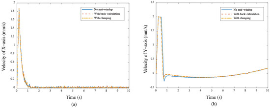
Figure 14.
The velocity responses under different cases (a) X–axis (b) Y–axis in Bézier curve.
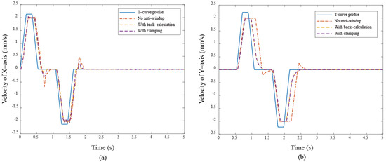
Figure 15.
The velocity responses under different cases (a) X–axis (b) Y–axis in quadrilateral curve.
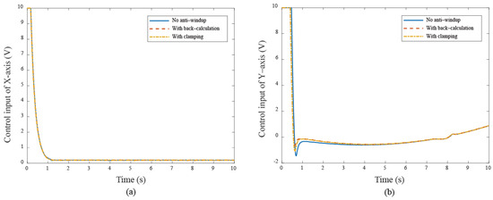
Figure 16.
The control input responses under different cases (a) X–axis (b) Y–axis in Bézier curve.
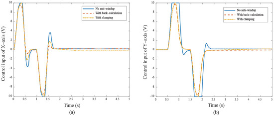
Figure 17.
The control input responses under different cases (a) X–axis (b) Y–axis in quadrilateral curve.
In summary, the anti-windup algorithms are significant while control systems meet on the integral windup conditions. The experimental results display excellent tracking performance along the specific Bézier and quadrilateral curves, showcasing how anti-windup algorithms effectively compensate input saturations, leading to superior performance. Meanwhile, it is also observed that the control performance that applied the back-calculation outperforms that using the clamping scheme. Although both the simulated and experimental systems have demonstrated feasibility and effectiveness in dealing with the wind-up problem, they still have distinguished results in transient responses due to existing unmodeld dynamics and parameter uncertainties between the simulation and physical systems.
5. Conclusions and Future Works
This study proposed and evaluated two anti-windup algorithms (i.e., back-calculation and clamping methods) for a servo-based X-Y platform. The state-space model of a two-axis servo motor system comparing control systems was introduced, and the control performance was compared with and without anti-windup algorithms through simulation and experimentation. Further, the Bézier and quadrilateral curves with T-curve velocity profile were planned. It turned out that using the back-calculation method achieves superior control performance by preventing severe tracking errors caused by integral windup, while the clamping method employs a simpler structure using a switch triggered by an input threshold. Trajectory tracking results show the back-calculation algorithm achieves the most precise positioning control, with errors of ±13.48 mm and ±19.88 mm in quadrilateral curve cases, and ±1.1 mm in Bézier curve cases. Both anti-windup algorithms demonstrate significantly improved performance, including reduced overshoot and faster settling time, effectively mitigating control input saturation effects. Future work will deal with cases with the consideration of other nonlinearities affecting the system and the event/self-triggered control.
Author Contributions
Conceptualization, C.-W.C. and H.-M.W.; methodology, C.-W.C., H.-M.W. and C.-Y.N.; validation, H.-M.W. and C.-Y.N.; writing—original draft preparation, C.-Y.N.; writing—review and editing, H.-M.W. and C.-Y.N.; supervision and funding acquisition, H.-M.W. and C.-Y.N. All authors have read and agreed to the published version of the manuscript.
Funding
This research received no external funding.
Data Availability Statement
Data are contained within this article.
Conflicts of Interest
The authors declare no conflict of interest.
References
- Min, C.; Pan, Y.; Dai, W.; Kawsar, W.; Li, I.; Wang, G. Trajectory optimization of an electric vehicle with minimum energy consumption using inverse dynamics model and servo constraints. Mech. Mach. Theory 2023, 181, 105185. [Google Scholar] [CrossRef]
- Udris, D.; Bručas, D.; Pomarnacki, R. Reliability Improvement of Power Distribution System for UAV. Electronics 2019, 8, 636. [Google Scholar] [CrossRef]
- Jiang, W.; Zhang, C.; Jia, P.; Yan, G.; Ma, R.; Chen, G. A Study on the Electro-Hydraulic Coupling Characteristics of an Electro-Hydraulic Servo Pump Control System. Processes 2022, 10, 1539. [Google Scholar] [CrossRef]
- Situm, Z. Applying different controller structures for position control of pneumatic servo system. Strojarstvo 2006, 48, 261–271. [Google Scholar]
- Dolleman, P.; Carneiro, J.F.; de Almeida, F. Exploring the use of two servo-valves for servo-pneumatic control. Int. J. Adv. Manuf. Technol. 2018, 97, 2963–3980. [Google Scholar] [CrossRef]
- Mehedi, I.M.; Ansari, U.; Al-Saggaf, U.M.; Bajodah, A.H. Controlling A Rotary Servo Cart System Using Robust Generalized Dynamic Inversion. Int. J. Robot. Autom. 2020, 35, 77–85. [Google Scholar] [CrossRef]
- Wos, P.; Dindorf, R. Adaptive Control of The Electro-Hydraulic Servo-System With External Disturbances. Asian J. Control. 2013, 15, 1065–1080. [Google Scholar] [CrossRef]
- Lin, F.; Chiu, S. Adaptive fuzzy sliding-mode control for PM synchronous servo motor drives. IEE Proc.-Control. Theory Appl. 1998, 145, 63–72. [Google Scholar] [CrossRef]
- Liu, X.; Chang, X. Adaptive event-triggered tracking control for nonlinear networked systems with dynamic quantization and deception attacks. Int. J. Robust Nonlinear Control. 2024, 34, 8311–8333. [Google Scholar] [CrossRef]
- Chen, W.; Xu, T.; Liu, J.; Wang, M.; Zhao, D. Picking Robot Visual Servo Control Based on Modified Fuzzy Neural Network Sliding Mode Algorithms. Electronics 2019, 8, 605. [Google Scholar] [CrossRef]
- Chang, X.; Liu, X.; Hou, L.; Qi, J. Quantized Fuzzy Feedback Control for Electric Vehicle Lateral Dynamics. IEEE Trans. Syst. Man Cybern. Syst. 2024, 54, 2331–2341. [Google Scholar] [CrossRef]
- Richter, A.; Rydlo, P.; Pustka, M.; Kolar, M. Pulse driving of piezoceramic actuators and their present technical limitations. Ferroelectrics 2005, 320, 593–600. [Google Scholar] [CrossRef]
- Gdoura, E.K.; Feki, M. Sliding Mode Control Applied to Electrohydraulic System. Appl. Sliding Mode Control. 2017, 79, 331–363. [Google Scholar]
- Tran, T.; Jung, J. Development of anti-windup PI control and bumpless control transfer methodology for feedwater control system. Ann. Nucl. Energy 2019, 131, 233–241. [Google Scholar] [CrossRef]
- Wittenmark, B.; Åström, K. Practical issues in the implementation of self-tuning control. Automatica 1984, 20, 595–605. [Google Scholar] [CrossRef][Green Version]
- Markaroglu, H.; Guzelkay, M.; Eksin, I.; Yesil, E. Tracking time adjustment in back calculation anti-windup scheme. In Proceedings of the 20th European Conference on Modelling and Simulation, Bonn, Germany, 28–31 May 2006; ISBN 0-9553018-0-7. [Google Scholar]
- Yang, M.; Tang, S.; Xu, D. Comments on Antiwindup strategy for PI-type speed controller. IEEE Trans. Ind. Electron. 2014, 62, 1329–1332. [Google Scholar] [CrossRef]
- Espina, J.; Arias, A.; Balcells, J.; Ortega, C. Speed anti-windup PI strategies review for field oriented control of permanent magnet synchronous machines. In Proceedings of the 13th European Conference on Power Electronics and Applications, Badajoz, Spain, 20–22 May 2009; pp. 279–285. [Google Scholar]
- Chen, Y.; Ma, K.; Dung, R. Dynamic Anti-Windup Design for Linear Systems with Time-Varying State Delay and Input Saturations. Int. J. Syst. Sci. 2022, 53, 2165–2179. [Google Scholar] [CrossRef]
- Wang, X.; Zhang, X. Neural-Network-Based Control for Discrete-Time Nonlinear Systems with Input Saturation Under Stochastic Communication Protocol. IEEE/CAA J. Autom. Sin. 2021, 8, 766–778. [Google Scholar] [CrossRef]
- Ju, Y.; Liu, Y.; Zhang, B. Finite-Horizon H∞ Filtering and Fault Isolation for a Class of Time-Varying Systems with Sensor Saturation. Int. J. Syst. Sci. 2021, 52, 321–333. [Google Scholar] [CrossRef]
- Li, P.; Zhu, G. IMC-based PID control of servo motors with extended state observer. Mechatronics 2019, 62, 102252. [Google Scholar] [CrossRef]
- Cheng, G.; Peng, K. Robust composite nonlinear feedback control with application to a servo positioning system. IEEE Trans. Ind. Electron. 2007, 54, 1132–1140. [Google Scholar] [CrossRef]
- Huba, M.; Chamaz, S.; Bistak, P.; Vrancic, D. Making the PI and PID Controller Tuning Inspired by Ziegler and Nichols Precise and Reliable. Sensors 2021, 21, 6175. [Google Scholar] [CrossRef]


Disclaimer/Publisher’s Note: The statements, opinions and data contained in all publications are solely those of the individual author(s) and contributor(s) and not of MDPI and/or the editor(s). MDPI and/or the editor(s) disclaim responsibility for any injury to people or property resulting from any ideas, methods, instructions or products referred to in the content. |
© 2025 by the authors. Licensee MDPI, Basel, Switzerland. This article is an open access article distributed under the terms and conditions of the Creative Commons Attribution (CC BY) license (https://creativecommons.org/licenses/by/4.0/).