Abstract
This paper presents an Application-Specific Integrated Circuit (ASIC) implementation and Field-Programmable Gate Array (FPGA) verification of a Convolutional Neural Network (CNN)-based Intrusion Detection System (IDS) designed to enhance the security of an in-vehicle Controller Area Network (CAN) BUS and detect malicious messages. The CNN model employs a lightweight architecture with a single convolution layer using a 2 × 2 kernel and integrates a filter algorithm optimized for Fuzzy and Spoofing attacks to improve the performance. The IDS is implemented on an Electronic Control Unit platform powered by an ARM Cortex-M3 core and uses SRAM to store the parameters utilized by the CNN model and filter algorithm, targeting ASIC implementation with TSMC 180 nm technology. Functional verification was conducted by configuring a simplified CAN bus environment using the Xilinx Nexys Video FPGA and PEAK-System PCAN-USB, which was validated in real-time against DoS, Spoofing, and Fuzzy attack scenarios. The proposed lightweight CNN-based IDS achieved a fast detection speed of 0.0233 ms and an average accuracy of 99.6879%, thereby demonstrating its potential to enhance the security of in-vehicle CAN BUS.
1. Introduction
The automotive industry has recently required significant computational performance due to the advances in Advanced Driving Assistance Systems (ADASs) and autonomous driving technologies [1,2]. Furthermore, the growing network connectivity with electric devices to accommodate various vehicle features has significantly elevated the importance of Controller Area Network (CAN) BUS, the primary communication protocol for vehicles [2,3].
The CAN bus enables efficient data exchange among various Electronic Control Units (ECUs) within the vehicle, thereby supporting a wide range of functionalities. However, owing to a lack of security features, they are vulnerable to malicious attacks. An attacker can gain access to a network and manipulate it, posing a serious threat to the safety of drivers and passengers [3].
To address the threats posed by the lack of security features, various models have been implemented to Intrusion Detection Systems (IDS) [4], such as Convolutional Neural Network (CNN)-based IDS using Inception-ResNet [5] and Generative Adversarial Networks (GAN)-based IDS using an Auxiliary Classifier [6]. However, Deep Learning approach is often unsuitable for vehicles due to its high computational complexity and the limited resources available in vehicle environments.
This paper proposes a lightweight CNN-based IDS using shallow learning to address the security vulnerabilities of the CAN BUS and establish an IDS for vehicle networks. The proposed approach includes Application Specific Integrated Circuit (ASIC) implementation and Field Programmable Gate Array (FPGA) verification of an IDS. The proposed IDS can be summarized as follows.
- The error-handling mechanism of the CAN protocol is utilized to impose communication penalties on the hacked ECU or isolate them from the bus.
- Data preprocessing methods, such as Sliding Window and Data Insertion, are utilized to facilitate the real-time analysis of ongoing communication data.
- The CNN model performs multiclass classification to identify attack types, and the corresponding filter algorithm is applied to mitigate performance degradation caused by the lightweight design.
2. Background
2.1. CAN
CAN is a network protocol designed to communicate among various ECUs within a vehicle. In the CAN protocol, each data packet is assigned a unique message ID to form a message-based communication structure [7,8]. This allows all ECUs within the network to control communication independently without a central control unit. Additionally, it provides error detection and recovery features capable of identifying and managing various types of errors.
Additionally, as shown in Figure 1, the ECU within a vehicle adopts a multi-master architecture, where collisions can occur if multiple ECUs attempt to communicate simultaneously. To prevent this, an arbitration process is performed to determine the communication priority. The arbitration process operates on a bit-level comparison. When a Dominant Bit (Logic 0) and a Recessive Bit (Logic 1) are transmitted simultaneously, the Dominant Bit takes precedence. Through this method, the message IDs are compared, and ultimately, the message with the lowest ID is assigned the highest priority.
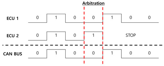
Figure 1.
Controller Area Network (CAN) arbitration procedure.
2.1.1. Frame
A CAN Frame is the basic unit of data transmission, containing the transmitted data, along with its associated control information. CAN Frames are categorized into four types: Data Frame, Remote Frame, Overload Frame, and Error Frame, each serving the following roles, respectively:
- Remote Frame: A frame used to request data associated with a specific message ID. It does not transmit any data but only includes the ID for the request.
- Overload Frame: A frame transmitted when the network is in an overloaded state, temporarily halting communication and requesting additional time for data processing.
- Error Frame: A frame transmitted when an error is detected, notifying the network of its occurrence.
- Data Frame: A frame used for actual data transmission, sending information from the transmitting ECU to receiving ECU.
In this study, only Error and Data Frames were considered. The CAN Data Frame is shown in Figure 2, and the role of each field is as follows.

Figure 2.
Data Frame structure.
The Start of Frame (SOF) is a single bit that signals the start of a frame, enabling the ECU connected to the network to recognize and synchronize the beginning of the frame accordingly.
The Arbitration Field contains the unique ID of the message and is responsible for determining its priority. It is composed of the Identifier (ID) and Remote Transmission Request (RTR). The ID is 11 bits long in the CAN Standard and 29 bits long in the Extended format. In this study, the Standard format is used, with the ID set to 11 bits. The RTR is a single bit used to differentiate between Data Frames and Remote Frames. A Dominant Bit is used to indicate a Data Frame.
The control Field contains information regarding the size and type of the Data Field of the current frame. It is composed of 6 bits, including Reserved Bits and the Data Length Code (DLC). The Reserved Bits are the two bits allocated to the future functionality. In this study, DLC was limited to values between 0 and 8.
The data Field contains the actual transmitted data. The size of the data is determined by the DLC, and the data are transmitted in the order of Most Significant Bit.
The CRC Field performs error detection in the frames. It is composed of a Cyclic Redundancy Check (CRC) Sequence and a Delimiter Bit. The CRC Sequence contained a 15-bit CRC value calculated using the SOF, Arbitration Field, Control Field, Data Field, and the CRC-15 Polynomial. The Delimiter Bit is a single Recessive Bit used to mark the end of a CRC Field. The transmitted CRC value in the CRC Sequence is compared with the CRC value calculated using the receiving ECU. If the values do not match, the receiving ECU can request the transmitting ECU to resend the frame.
The ACK Field indicates to the transmitting ECU whether data were successfully received by the receiving ECU. It comprises an ACK Slot and the Delimiter Bit. If the data were successfully received, a Dominant Bit was transmitted in the ACK Slot.
The End of Frame (EOF) is the field that signals the End of Frame. It comprises seven consecutive Recessive Bits.
The Interframe Space (IFS) represents the gap between frames. It consists of three consecutive Recessive Bits indicating the minimum interval between frames. This prevents collisions between consecutive frames and enhances communication reliability.
2.1.2. Error Handling
CAN communication detects and manages errors in stages such as error detection, error counter management, and error state transitions. It can identify five types of errors: Bit, Stuff, CRC, Form, and ACK Error.
A Bit Error occurs when the bit transmitted by the sending ECU is different from the actual bit received by the CAN BUS. However, exceptions include cases where a Stuff Bit or the ACK Slot is transmitted as a Dominant Bit, in which no Bit Error is triggered [7,8]. In addition, Bit Errors do not occur when a transmitting ECU in the Passive Error Flag state detects a Dominant Bit.
A Stuff Error occurs when the sixth consecutive identical bit appears in an encoded Frame Field, violating the bit-stuffing rule. As shown in Figure 3, bit-stuffing is used to maintain synchronization and assist in error detection during data transmission. This method inserts the opposite bit when five identical consecutive bits are detected.
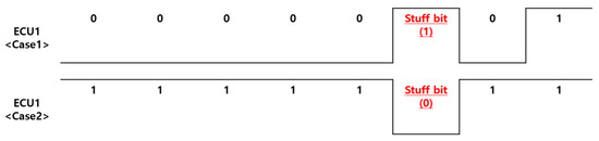
Figure 3.
Bit Stuffing.
A CRC Error occurs when the CRC value calculated by the receiving ECU is different from the CRC value transmitted by the sending ECU.
Form Error occurs when a fixed-format Bit Field, such as a Delimiter Bit or EOF contains a bit that does not conform to the required format. However, a Form Error does not occur if the receiving ECU detects a Dominant Bit in the last bit of the EOF or monitors a Dominant Bit in the last bit of the Error Delimiter.
An ACK Error occurs when, after sending a message, the transmitting ECU detects a Recessive Bit in the ACK Slot instead of a Dominant Bit from the receiving ECU connected to a CAN BUS.
The ECUs connected to the CAN BUS exist in one of three error states, as shown in Figure 4. These states are managed through a Transmission Error Counter (TEC), which counts errors occurring during transmission, and the Receive Error Counter (REC), which counts errors occurring during reception. When an error is detected, the TEC typically increases by eight and the REC increases by one [5,6]. Conversely, when communication occurs without errors, both the TEC and REC decrease by 1.
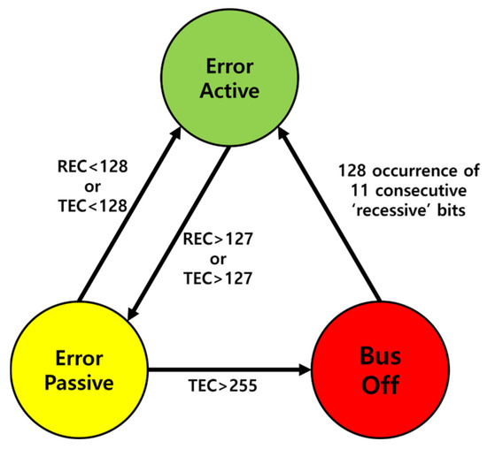
Figure 4.
Error state.
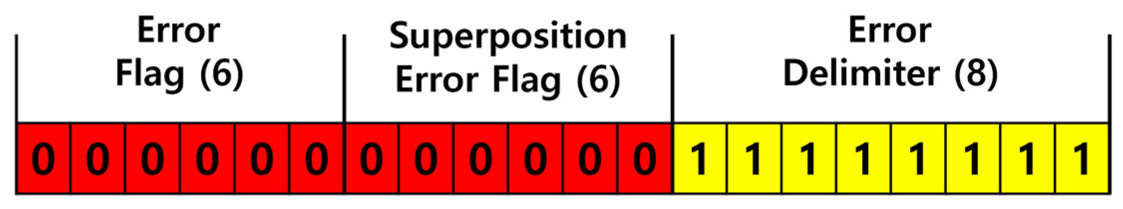
Error Active is the default state of an ECU that allows normal participation in CAN BUS communication. When either the TEC or REC reaches 128, the state transitions to Error Passive. If the counters fall below 128, the state reverts to Error Active. Additionally, when an error occurs, the ECU transmits an Active Error Frame, as shown in Figure 5.
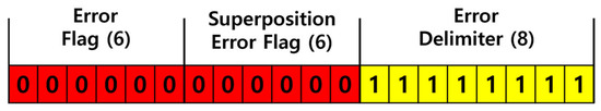
Figure 5.
Active error frame.
Passive error is a state in which the ECU transmits a Passive Error Frame when an error occurs, as shown in Figure 6. After transmitting the Passive Error Frame, any subsequent transmission requires the ECU to wait before retrying. If TEC exceeds 255, the ECU transitions to a bus-off state.
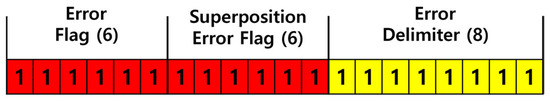
Figure 6.
Passive error frame.
A bus-off is a state in which the ECU can no longer participate in communication and cannot influence the bus. This occurs when an ECU is isolated from the network. If 11 consecutive Recessive Bits are detected 128 times on the bus, the TEC and REC are reset to zero, and the ECU transitions back to the error-active state.
2.1.3. Attack Type
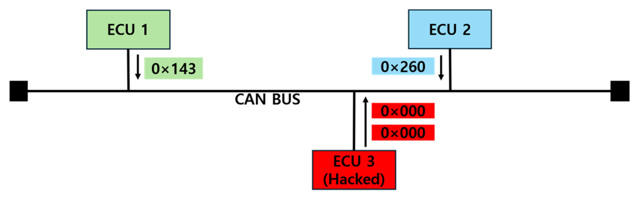
Network attacks within vehicles involve hacking an ECU to inject malicious messages into the CAN BUS, thereby disrupting the normal functionality of the vehicle [9]. This study addresses Denial of Service (DoS), Fuzzy, and Spoofing attacks.
DoS Attack is, as shown in Figure 7, where a hacked ECU leverages the CAN communication arbitration process to send a large number of low-priority messages, disrupting normal communication. By transmitting these messages repeatedly at short intervals, an attack can saturate the CAN BUS, thereby preventing the transmission of legitimate messages.

Figure 7.
DoS attack.
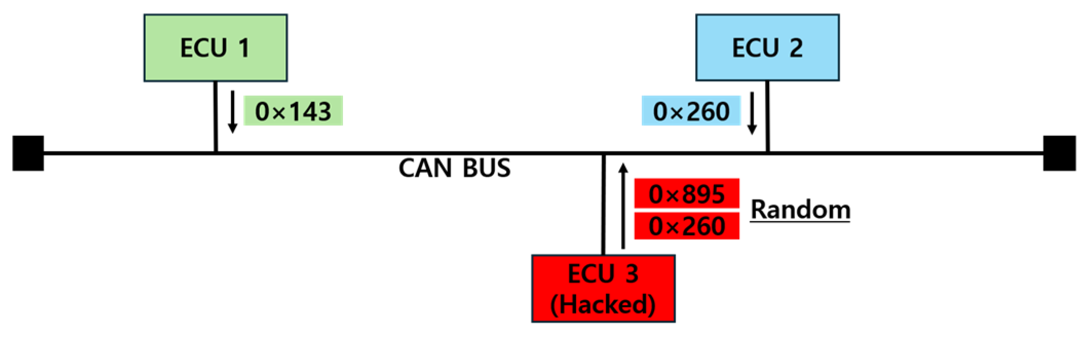
A Fuzzy Attack, as depicted in Figure 8, involves transmitting messages with randomly generated IDs and data to the CAN BUS. This disrupts the transmission of legitimate messages and causes devices to malfunction. From the perspective of the hacker, the attack is relatively simple to execute, as it only requires sending messages with random IDs and data. However, these messages are uncommon in normal communication scenarios, which makes them easier to detect from the perspective of an IDS.

Figure 8.
Fuzzy attack.
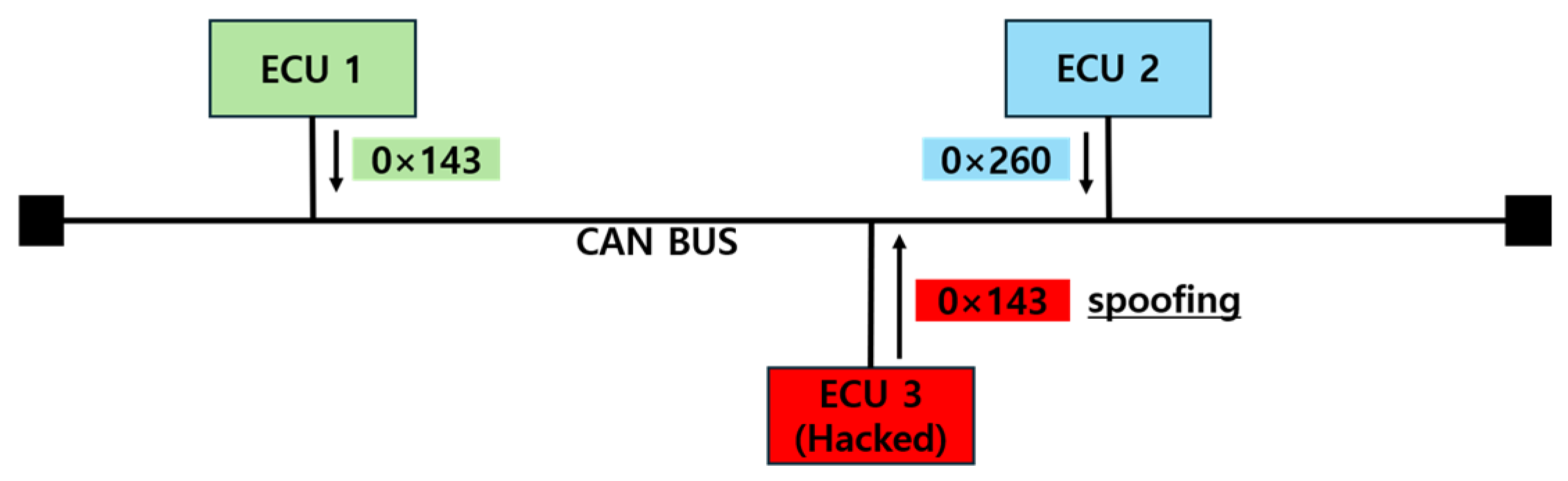
A Spoofing Attack, as shown in Figure 9, occurs when a compromised ECU monitors messages transmitted on the CAN BUS for a period of time and then impersonates a legitimate ECU to send false data to the bus. By mimicking a specific ECU, the attack causes other ECUs to operate based on incorrect information. In some cases, the attack replicates the exact data of legitimate messages, making a distinction between normal and malicious messages difficult for the receiving ECU. This makes the attack particularly dangerous from the perspective of the driver.

Figure 9.
Spoofing attack.
3. CNN-Based Intrusion Detection System Model
3.1. CNN Model
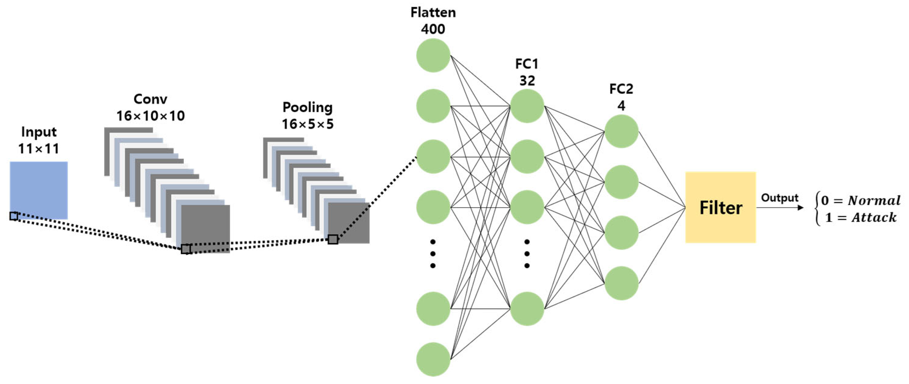
This study proposes a lightweight CNN model with a simplified Multi-Layer Perceptron (MLP) structure and a single convolution layer, based on shallow learning designed for a vehicle IDS, as shown in Figure 10.
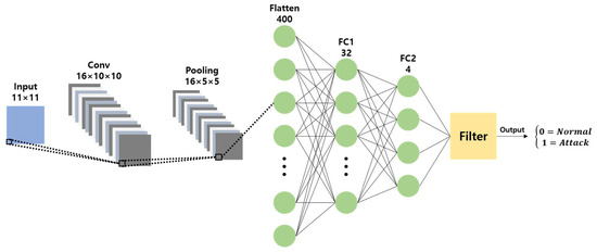
Figure 10.
Proposed CNN model.
The proposed model uses 11 CAN IDs, each consisting of 11 bits, as the input. It uses a 16 × 2 × 2 kernel to form a 16 × 10 × 10 convolution layer, followed by a 2 × 2 filter to construct a 16 × 5 × 5 max-pooling layer. The processed data are then passed through two fully connected layers. The first fully connected layer reduces the input of 400 nodes to 32 nodes, and the second fully connected layer further reduces the input to four nodes. These four nodes represent the classification results, indicating whether the current CAN BUS message is normal, or belongs to one of the following attack types: DoS, Fuzzy, or Spoofing. Based on the detected attack type, the message was processed using the corresponding filter algorithm [10] to determine whether it was an actual attack.
3.2. Data Preprocessing
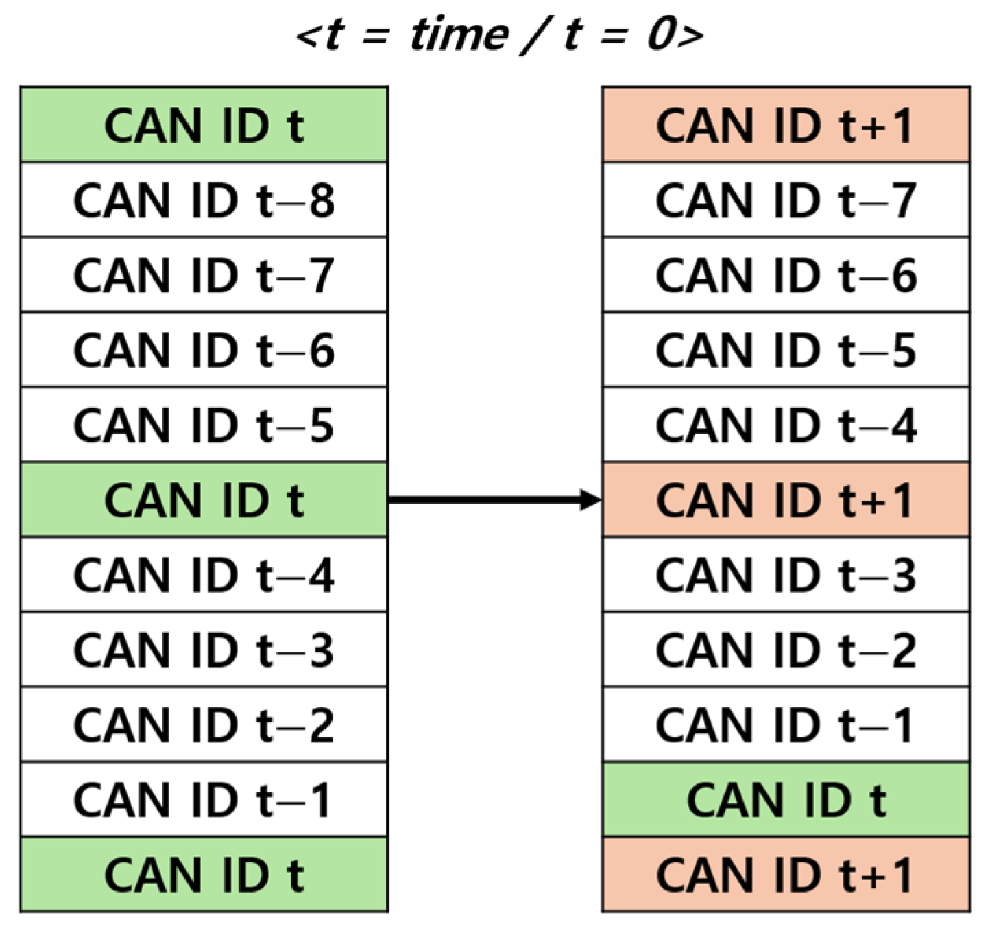
The lightweight CNN model used in this study is designed to process the status of data frame shown in CAN BUS in real time, as shown in Figure 11, 11-bit CAN IDs were preprocessed using Sliding Window and Data Insertion method to generate a convolution layer input in the form of 11 × 11.
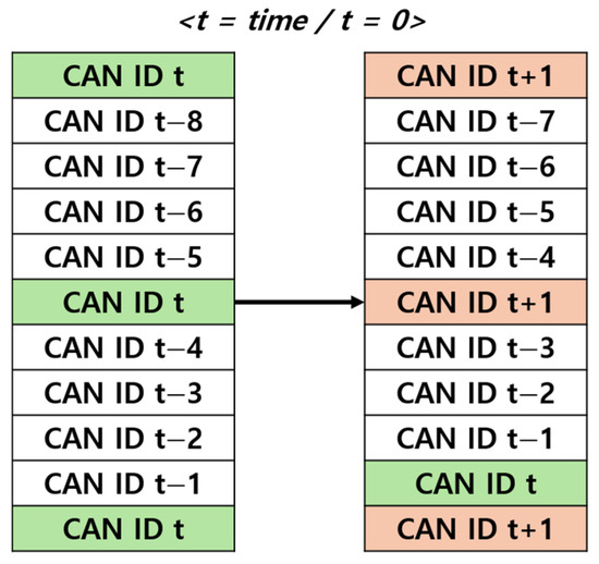
Figure 11.
Proposed data preprocessing.
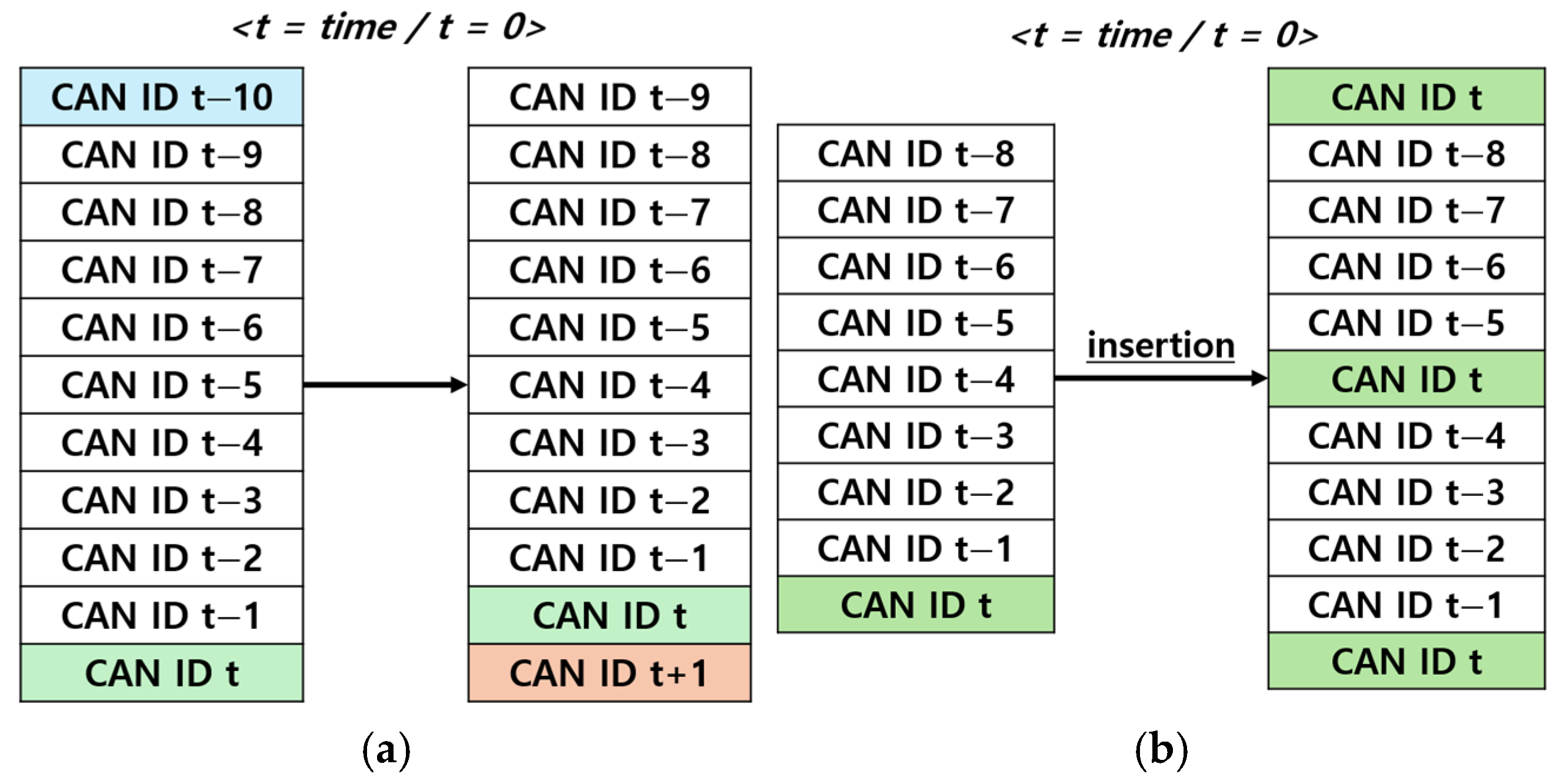
A Sliding Window is a technique that processes specific segments of continuous data by selecting and shifting them over a defined range. In this study, as shown in Figure 12a, the current CAN ID on the CAN BUS is placed at the bottom of the matrix, whereas the earliest received CAN ID is positioned at the top. When a new CAN ID arrives, the earliest CAN ID is removed, and the previous data shift upward, creating space for the current CAN ID at the bottom. This approach has the advantage of allowing individual evaluation of each CAN ID. However, this poses challenges in assessing the state of current CAN ID because of the emphasis on historical data.
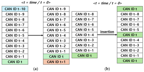
Figure 12.
(a) refers to the sliding window and (b) refers to the data insertion.
Data Insertion is a preprocessing technique used to address the difficulty of assessing the state of the current CAN ID in the Sliding Window method. As shown in Figure 12b, this technique appends the three most recent CAN IDs to the previous eight CAN IDs to create an 11×11 structure. By placing more emphasis on the current CAN IDs, this method provides the advantage of evaluating the state of the current CAN ID more accurately.
3.3. Filter
The lightweight CNN model proposed in this study, which uses only a single convolutional layer, shows a lower performance compared to standard CNNs. To address this limitation, a Cross-Check Rule-Based Filter algorithm is introduced to enhance the detection capabilities of the model [10]. Of the three available filter algorithms, this study focuses on those targeting Spoofing and Fuzzy attacks because these demonstrate significant performance degradation.
For DoS Attacks, rely solely on the IDS determination results without using the filter algorithm. For Spoofing Attacks, the filter algorithm was refined by revising Rule 2 and introducing Rule 3. For Fuzzy Attacks, modifications included removing Rule 1 and adjusting Rule 2. These improvements were made to enhance detection accuracy while maintaining compatibility with the lightweight CNN-based IDS.
The Spoofing Filter Algorithm detects Spoofing attacks that exploit normal IDs by assigning predefined values to each normal ID. To determine if an attack is taking place, the algorithm compares this value with the number of times the IDS has identified the attacked ID as malicious (Rule 1). Additionally, because Spoofing attacks often use the same ID with repeated Data Fields, the algorithm calculates and compares the Hamming Distance between Data Fields of the same ID to determine if an ongoing attack (Rule 2). Because normal communication can also involve the use of the same ID with repeated Data Fields, the algorithm mitigates performance degradation caused by Rule 2 by reviewing previous IDS results for the same ID to make a final determination (Rule 3). (Algorithm 1).
| Algorithm 1: Spoofing Attack |
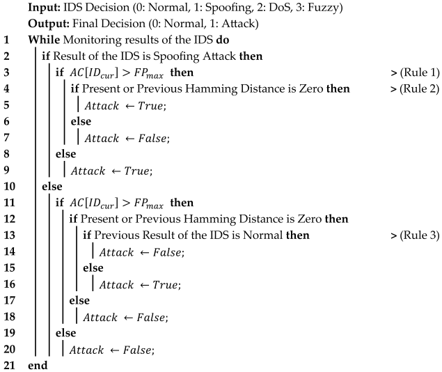 |
The Fuzzy Filter Algorithm detects Fuzzy attacks that involve the transmission of randomly generated IDs and Data Fields by analyzing the Hamming Distance between Data Fields with the same ID in normal data. The algorithm determines the maximum Hamming Distance, from the normal data and compares it with the Hamming Distance between Data Fields with the same ID during communication to identify an attack (Rule 1). Because randomly transmitted IDs and Data Fields typically exhibit higher Hamming Distances than normal IDs and Data Fields, the algorithm can effectively detect such attacks. (Algorithm 2).
| Algorithm 2: Fuzzy Attack |
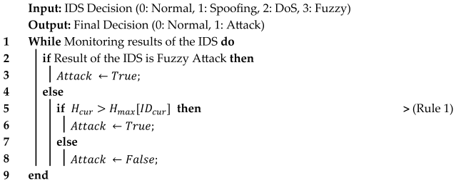 |
4. Hardware Implementation
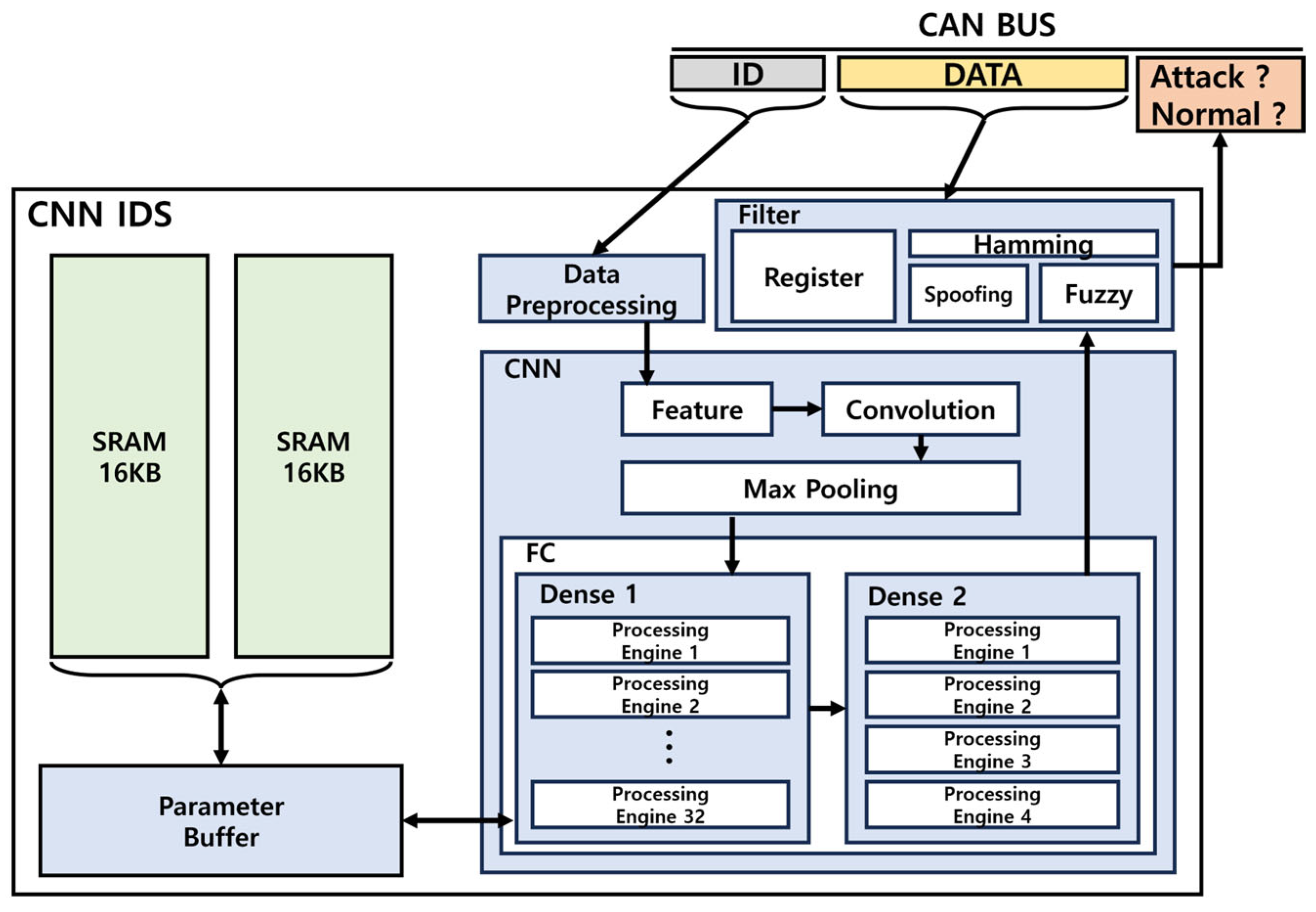
The hardware architecture of an in-vehicle IDS using a lightweight CNN model is shown in Figure 13. The IDs transmitted on the CAN BUS were processed using Data Preprocessing to form an 11 × 11 input structure, which was converted to match the kernel size for feature extraction. The converted values are used for Convolution and Max Pooling, followed by operations in Dense Layer 1 and 2. Finally, the data communicated on the CAN BUS and the output from Dense Layer 2 were provided as inputs to the filter, which produced the final attack determination.
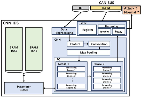
Figure 13.
Hardware structure of vehicle IDS.
4.1. Parameter
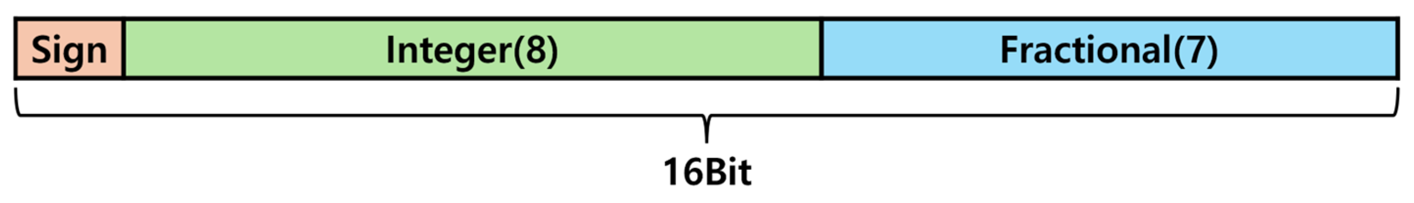
This study presented a lightweight CNN model tailored for in-vehicle networks, trained using 32-bit floating-point data. However, this format leads to high resource consumption and slower detection speeds when implemented in hardware [11].
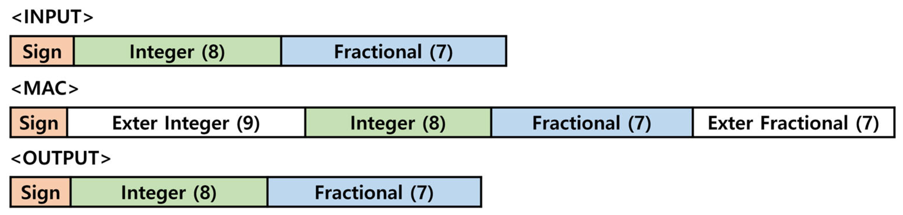
To overcome these challenges, as shown in Figure 14, a fixed-point representation was adopted, eliminating the need for normalization. Additionally, all parameters were quantized to 16 bits. This optimization effectively reduced resource usage and enhanced detection speed.
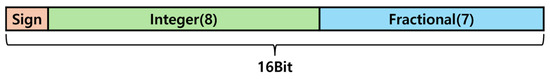
Figure 14.
Fixed point.
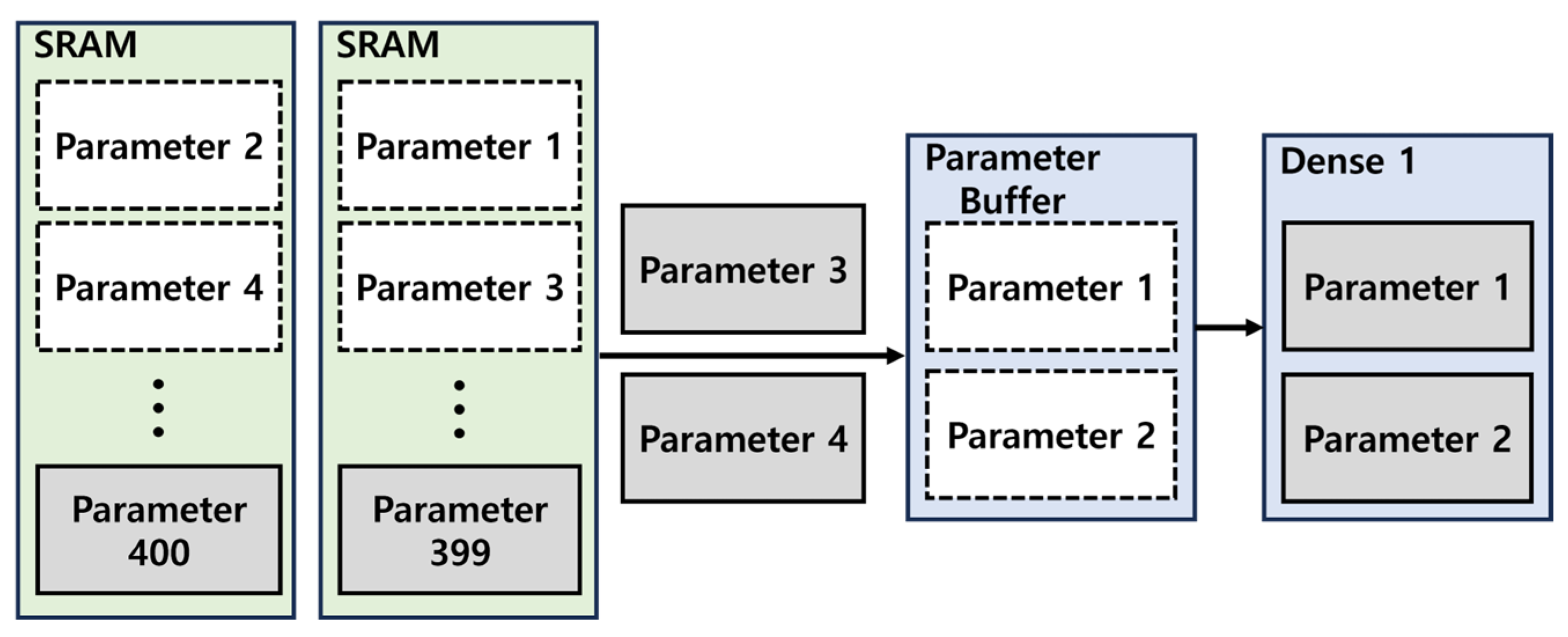
Additionally, two 16 KB SRAM modules were utilized to store the parameters required for the CNN and filter. To enable real-time attack detection on messages transmitted over the CAN BUS, as shown in Figure 15, the parameters required for the next operation are preloaded from the SRAM into the buffer while the Dense Layer 1 computation is underway [12,13]. This approach ensures seamless execution of subsequent operations, enabling uninterrupted real-time processing.
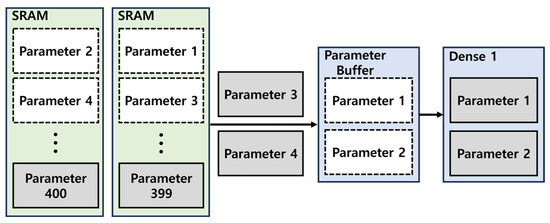
Figure 15.
Parameter buffer operation.
4.2. Convolution, Max Pooling, Fully Connected Layer
The main operations in a CNN are performed by the convolution layer and the pooling layer, which require optimization for hardware implementation [14,15,16].
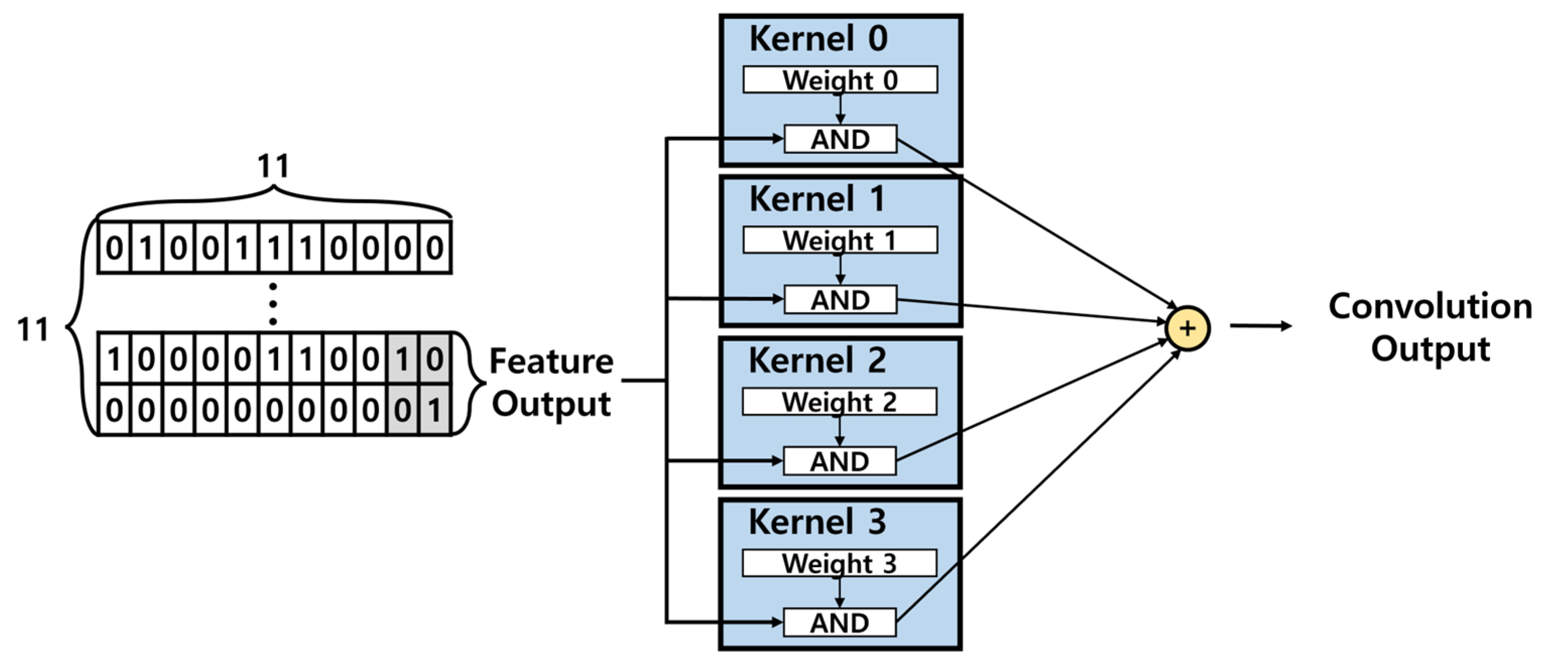
This study utilizes the hardware architecture of the convolution layer, as shown in Figure 16, where 11 × 11 input is processed through feature extraction and transformed into a 2 × 2 output. Feature input value consists of binary values (1 and 0), allowing the multiplication operations in the convolution process to be replaced by AND operations. This approach significantly reduces resource usage and optimizes the hardware for real-time processing.
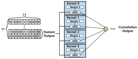
Figure 16.
Convolution layer hardware architecture.
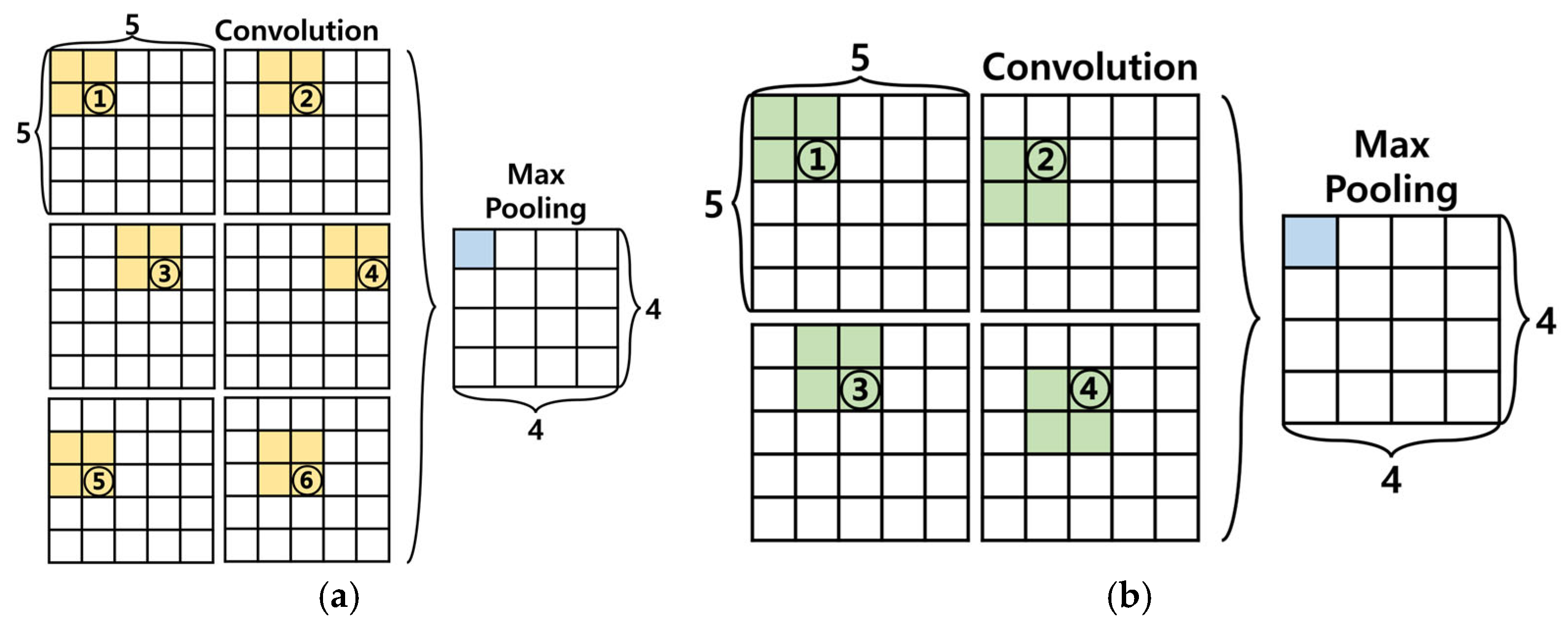
Additionally, we propose modifying the computational sequence shown in Figure 17a to the sequence shown in Figure 17b, for only four values required for Max Pooling were processed through convolution operations and stored in the registers for comparison. By performing computations only on necessary values, this method reduces resource usage and, regardless of the input format, the Max Pooling result can be output in only four cycles, minimizing the latency.
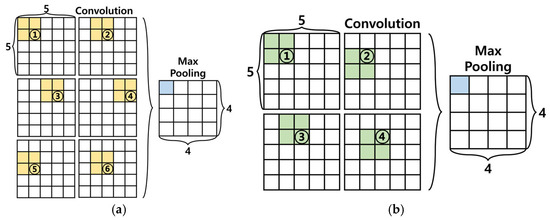
Figure 17.
(a) refers to the standard sequence of operations in a convolution process, and (b) represents the modified convolution process proposed in this study for hardware implementation.
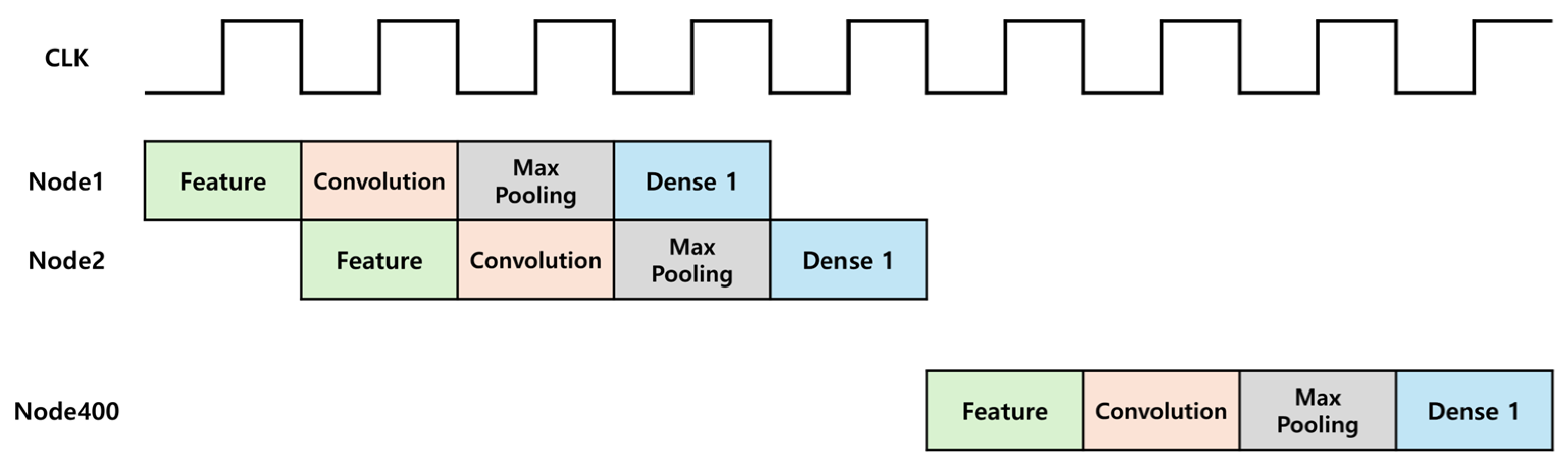
By modifying the computation sequence, the Feature, Convolution, Max Pooling, and Fully Connected Layer 1 operations can be structured into a pipelined architecture, as shown in Figure 18. According to Table 1, comparing the parallel processing of Convolution and Max Pooling operations with their reuse in a pipelined structure shows a 65% reduction in LUT usage. However, this increased detection time, which is a drawback. This is addressed by comparing the detection time with the criteria for determining whether the current message in the CAN communication is valid. The results show that even with a longer detection time, the determination of attack for the current frame is possible. Regarding ECU transmission, a message can be considered valid if no errors occur up to the last bit of the EOF. Similarly, for receiving ECU, a message is considered valid if no errors occur up to the bit immediately preceding the last bit of the EOF. Considering the worst-case scenario with a CAN communication speed of 500 Kbps, DLC of 0, and no Stuff bits, the minimum time required to invalidate a message is calculated as follows:
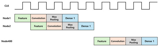
Figure 18.
Timing diagram of the lightweight CNN model.

Table 1.
Performance comparison based on pipelining and execution order.
To invalidate a message, the transmitting ECU must detect an error within , whereas the receiving ECU must detect an error within . Thus, the proposed IDS in this study is sufficient to detect attacks and invalidate the message because it has a detection time of . Additionally, by implementing a pipelined structure, the Dense 1 operation can proceed without the need for a flattening process, which means that no additional registers are required.
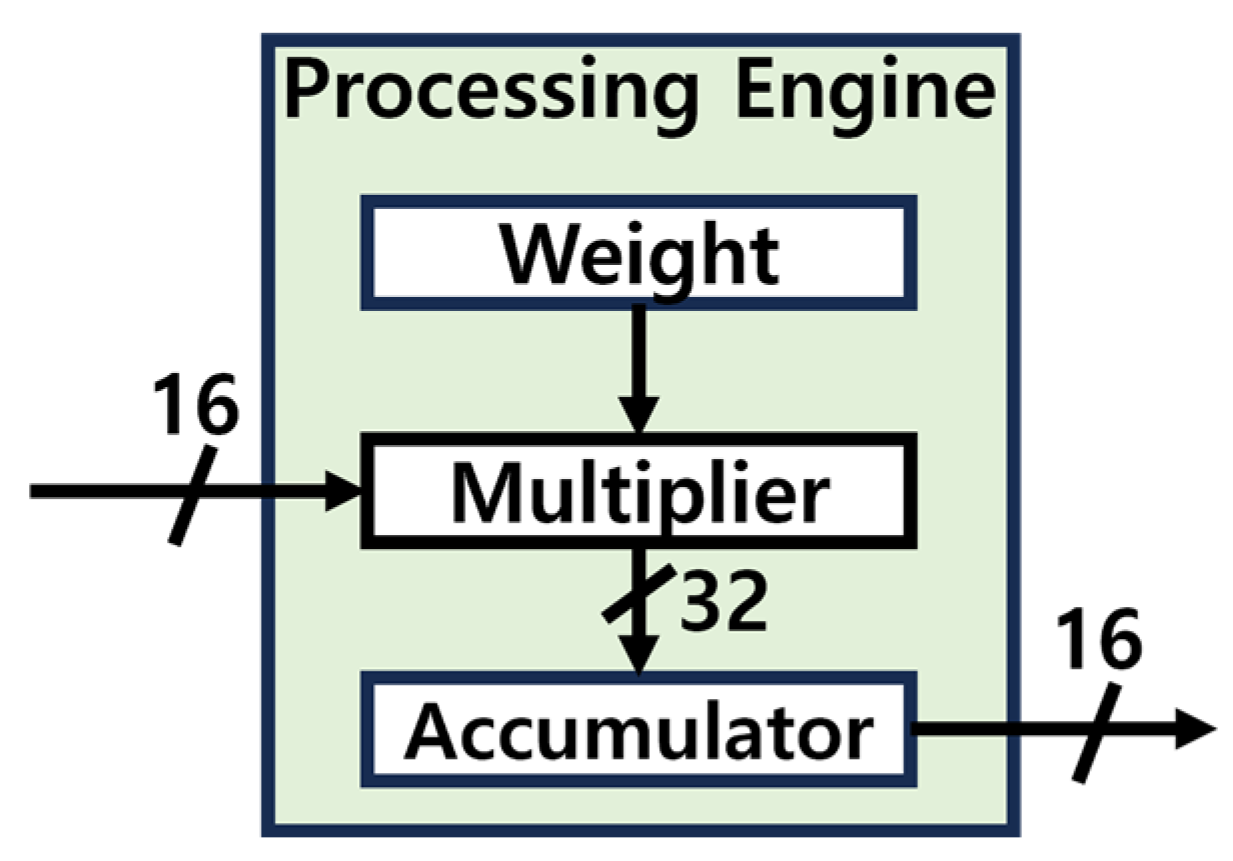
This study utilized the structure of the Processing Engine as shown in Figure 19, within the Fully Connected Layer. The Processing Engine receives a 16-bit input and executes the Multiply-Accumulate (MAC) operation, but during computation, overflow may occur due to the limitations of the 16-bit fixed-point representation. To address this issue, as depicted in Figure 20, the 16-bits input is extended to 32-bits during the MAC operation [17,18]. Once the computation is complete, the result is converted back to 16-bits for output. This approach effectively resolves the overflow problem while enhancing the accuracy of the computation process.
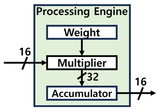
Figure 19.
Processing engine structure.

Figure 20.
Bit extensions in MAC operations.
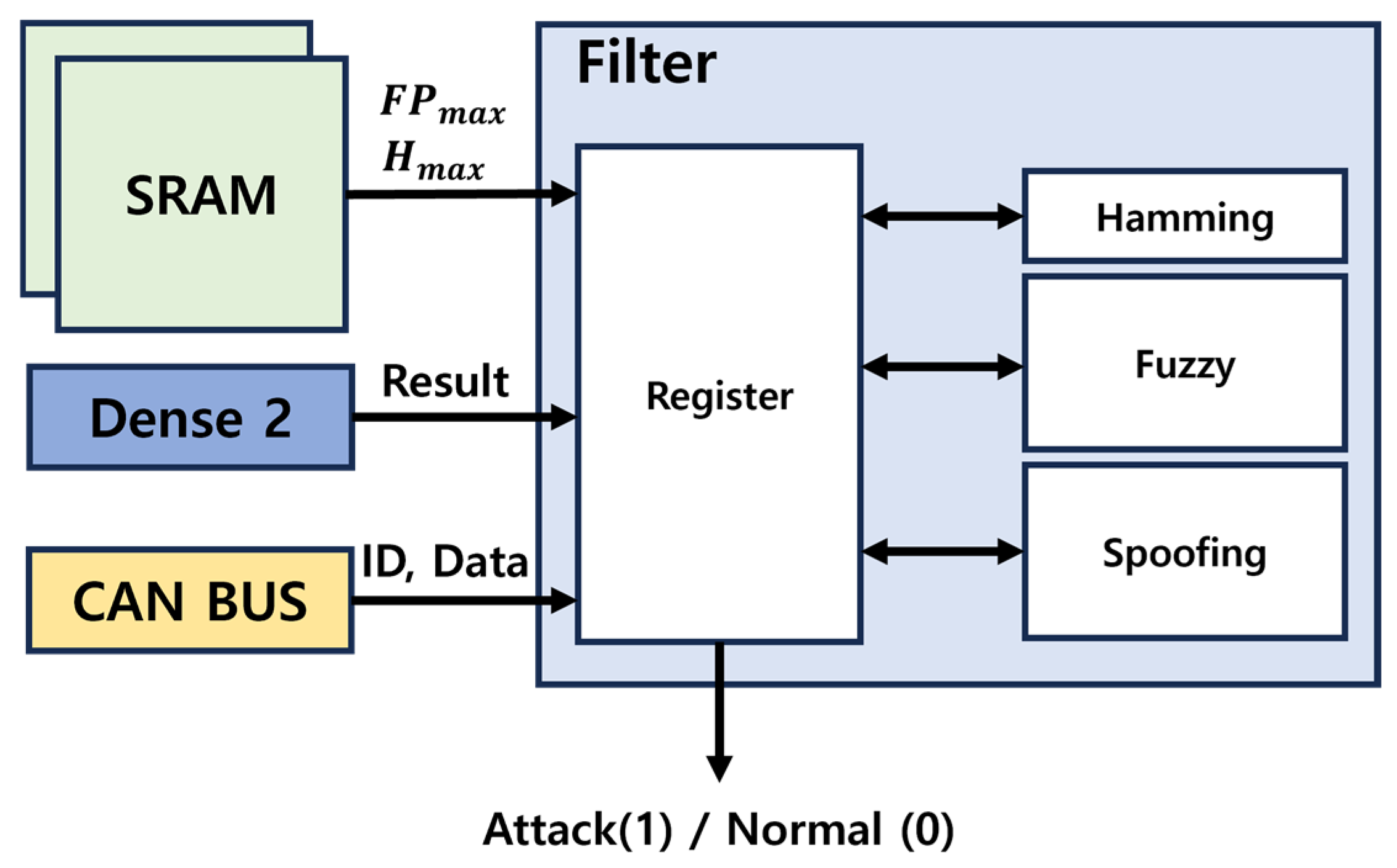
4.3. Filter
The hardware design of the filter structure is shown in Figure 21. The filter register is a crucial component in the process. At the start of CAN communication, it reads and stores the values of and values from the SRAM, which are essential for the Spoofing and Fuzzy attack detection algorithms. During communication, the register also holds the current CAN ID, DATA, Hamming Distance, and attack counter. The output from Dense 2 is routed to all detection algorithms. If no attack is identified, the output is marked as Normal (Logic 0). Conversely, if a Fuzzy, DoS, or Spoofing attack is detected, the output is marked as Attack (Logic 1), triggering an Error Frame on the CAN BUS.
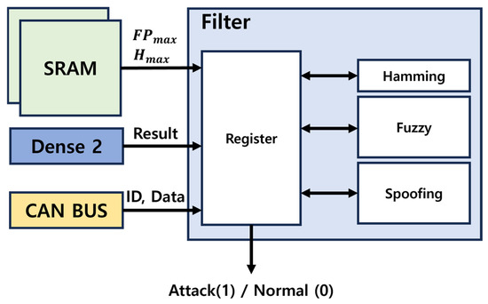
Figure 21.
Filter hardware structure.
5. Validation and Performance Evaluation
5.1. Verification Environment
In this study, the dataset configuration used for training the lightweight CNN model in the IDS is shown in Table 2. This dataset was constructed by recording CAN traffic from a real vehicle through the OBD-II port. The DoS attack uses CAN ID “0×000”, the Fuzzy attack utilizes random values for both CAN ID and DATA, and the Spoofing attack uses information related to RPM and Gear, along with the corresponding CAN ID [5,9,19,20]. Additionally, the dataset configuration used for verification, with 100,000 instances of each attack type used for testing is shown in Table 3.
Table 2.
Configuring the dataset used to train the lightweight CNN model.
Table 3.
Configuring the data set used for FPGA validation.
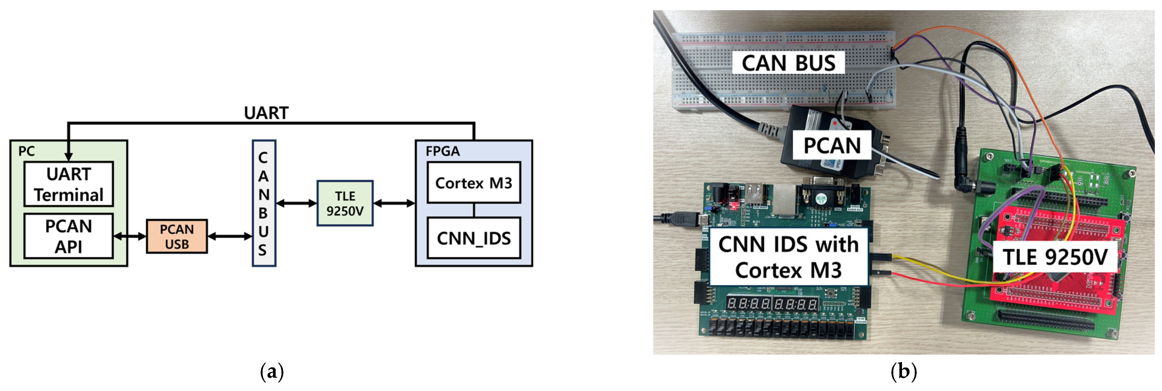
The FPGA verification environment used to validate the real-time response of the lightweight CNN-based IDS proposed in this study is shown in Figure 22. The verification environment utilizes Universal Asynchronous Receiver Transmitter (UART) communication was used to transmit the IDS results to a PC, and the PEAK system’s PCAN-USB was employed to implement the transmitting ECU on the CAN BUS. An API was developed in Python to control PCAN-USB. The TLE 9250 V transceiver was used to convert the CAN-H and CAN-L signals, as well as for RX and TX signal conversion. In addition, a Nexys Video FPGA board was selected for debugging to provide the necessary resources for the verification process. The verification sequence is as follows.

Figure 22.
(a) the block diagram of the FPGA environment for IDS verification; (b) the actual FPGA environment configured for IDS verification.
- Transmit the test data to the CAN BUS through the PCAN USB using the PCAN API.
- Transmit data from the CAN BUS to the FPGA, where the verification system is implemented via a transceiver.
- The FPGA board transmits signals, such as ACK and error flags, to the CAN BUS while sending the IDS results to the PC via UART.
To check for errors during the transmission and reception processes, PCAN View and an oscilloscope were used to monitor the transmission/reception waveforms and data.
5.2. Performance Evaluation
We compared the performance of different data preprocessing methods applied to the same lightweight CNN model, utilizing dataset used for model training, to verify that the proposed Data Insertion method can assist in determining attacks in real time. Specifically, we evaluated the performance of using the Sliding Window method alone and the combined approach of Sliding Window and Data Insertion. As shown in Table 4, the combined approach of Sliding Window and Data Insertion achieved a 10% performance improvement compared to using the Sliding Window method alone.
Table 4.
Comparison of accuracy based on data preprocessing methods.
For IDS performance evaluation on the FPGA, 100,000 test datasets were used, and the evaluation was based on the metrics of accuracy, precision, recall, and F1-Score. The accuracy represents the ratio of correct predictions made by the IDS. Precision refers to the proportion of actual attacks among instances that the IDS identified as attacks. Recall measures the proportion of actual attacks correctly identified by an IDS. The F1-Score is the harmonic mean of precision and recall, offering a balanced evaluation, particularly for imbalanced datasets.
For this evaluation, the following terms were defined: True Positive (TP) refers to instances in which the IDS correctly identified an attack, and True Negative (TN) refers to instances in which the IDS correctly identified a normal message. A false Positive (FP) refers to instances in which the IDS incorrectly identifies a normal message as an attack, and a False Negative (FN) refers to instances in which the IDS incorrectly identifies an attack as normal.
The software and hardware performance metrics for the lightweight CNN model with filters applied are shown in Table 5 and Table 6. An evaluation was conducted for four types of attacks: DoS, Fuzzy, Gear (Spoofing), and RPM (Spoofing). The data format used in the software implementation was a 32-bit floating point, whereas the hardware implementation utilized a 16-bit fixed-point representation.
Table 5.
Lightweight CNN model software performance indicators.
Table 6.
Filter application performance indicators of lightweight CNN-based IDS implemented in hardware.
A comparison of the results shows that the hardware implementation outperformed the software in some aspects. This improvement is attributed to the difference in the Bit Resolution that occurs when converting from a 32-bit floating point to a 16-bit fixed point during hardware implementation. The CNN model did not achieve the highest possible results because of its lightweight design. A filter algorithm was applied to address this reduced performance. As listed in Table 6, the performance of the model improved significantly, with notable increases in the Recall for the Fuzzy attack and Precision for the Spoofing attack.
The time required by different IDS models to determine an attack is shown in Table 7. The proposed IDS is shown to be 0.22 ms faster on average than the fast detection models, QMLP and BNN. As shown in Table 8, the proposed IDS was implemented with 70% fewer LUTs and 85% fewer FFs than the QMLP, with a memory requirement of 0.288 MB. Additionally, similar to the BNN, the proposed model can perform multiclass classification to determine the type of attack and can also use the filter algorithm for binary classification to detect attacks.
Table 7.
Comparison of inference time with other IDS models.
Table 8.
Metric comparison of proposed IDS and other FPGA implementation cases.
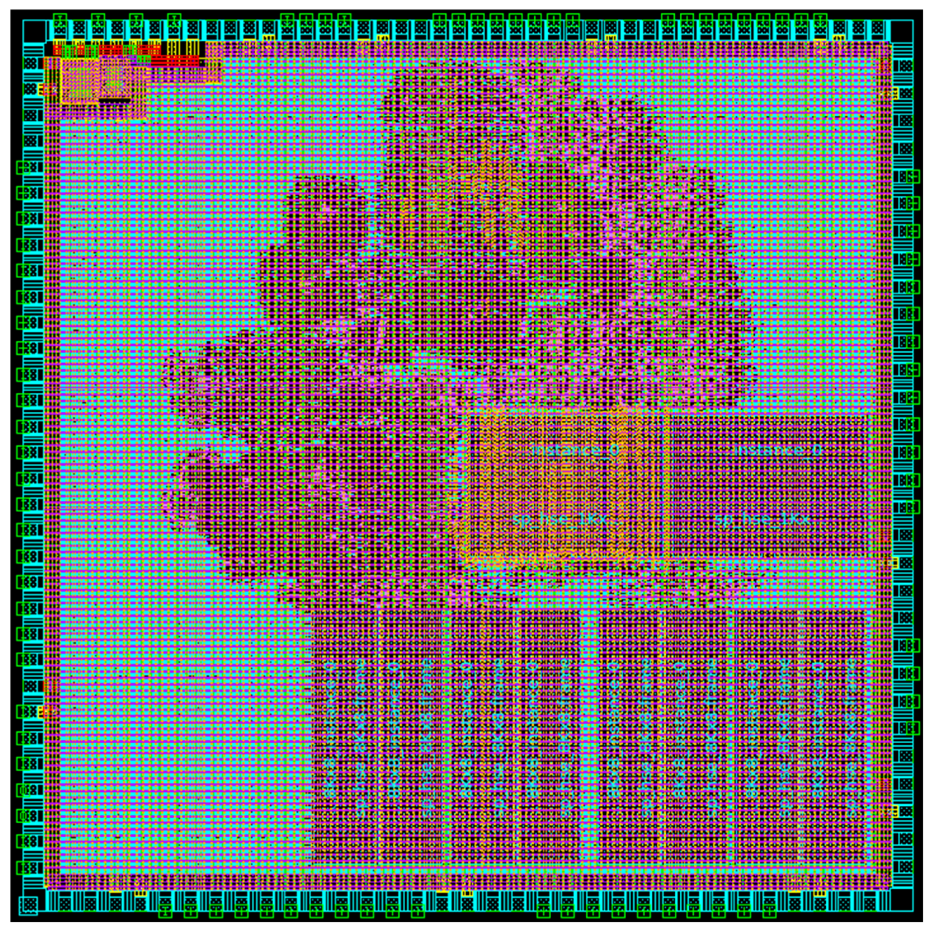
The results of the ASIC implementation of the CNN-based IDS proposed in this study are shown in Table 9. The implementation was based on the TSMC 180 nm process and Synopsys Design Compiler, with a die size of 5000 µm × 5000 µm. The clock used in the ASIC for the IDS was set to 50 MHz, and the Gate Count was calculated based on a 2-input NAND gate. The IDS, including the SRAM used for storing parameters, occupies 39.1762% of the total chip area, while the remaining portion consists of the Cortex-M3 and Debug Logic, and SRAM used by the Core. The utilized area of the total chip is shown in Figure 23, while the blue section represents the unused area.
Table 9.
ASIC implementation of proposed IDS.

Figure 23.
Physical layout.
6. Conclusions
This study aims to detect attacks on in-vehicle networks using a Shallow Learning-based lightweight CNN IDS. The lightweight CNN employs a single Convolution Layer and applies data preprocessing methods such as Sliding Window and Data Insertion for real-time detection. In hardware implementation, the use of a fixed-point representation that does not require normalization, and a pipelined structure resulting from changes in the Convolution operation order, lead to reductions in both resource usage and delay. Additionally, performance degradation caused by the lightweight design is mitigated by up to 8.1121% through the application of filter algorithms to handle Fuzzy and Spoofing attacks.
A total of 400,000 attack injection dataset were used to verify the real-time detection and response actions for DoS, Fuzzy and Spoofing attacks. Despite being implemented utilizing 17,059 LUTs and 191,376 gates, the Shallow Learning-based CNN IDS achieved an accuracy of 99.6879% and a recall of 99.8014% across these three types of attacks. However, the proposed model uses supervised learning, which has the limitation of being unable to detect attack types not present in the training data. This is a known limitation of supervised learning-based IDS. In future research, we plan to implement an IDS with lower resource usage and reduced delay by utilizing an unsupervised
Author Contributions
Conceptualization, M.C.; methodology, M.C. and M.L.; software, H.I. and J.L.; validation, M.C. and M.L.; formal analysis, M.C. and M.L.; investigation, M.C.; resources, M.C.; data curation, M.C. and H.I.; writing—original draft preparation, M.C.; writing—review and editing, J.L. and S.L.; visualization, M.C.; supervision, J.L. and S.L.; project administration, S.L.; funding acquisition, S.L. All authors have read and agreed to the published version of the manuscript.
Funding
This research was supported in part by the National R&D Program through the National Research Foundation of Korea (NRF) funded by the Ministry of Science and ICT (2021M3H2A1038042) and in part by the R&D Program of the Ministry of Trade, Industry, and Energy (MOTIE) and the Korea Evaluation Institute of Industrial Technology (KEIT) (RS-2022-00154973, RS-2023-00232192, and RS-2024-00403397) and in part by the Technology Innovation Program funded by the Ministry of Trade, Industry, and Energy (MOTIE) (RS-2024-00433615).
Data Availability Statement
Available online: https://ocslab.hksecurity.net/Datasets/car-hacking-dataset (accessed on 13 December 2024).
Acknowledgments
The EDA tool was supported by the IC Design Education Center (IDEC) in the Republic of Korea.
Conflicts of Interest
The authors declare no conflicts of interest.
References
- Okuda, R.; Kajiwara, Y.; Terashima, K. A Survey of Technical Trend of ADAS and Autonomous Driving. In Proceedings of the Technical Papers of 2014 International Symposium on VLSI Design, Automation and Test, Hsinchu, Taiwan, 28–30 April 2014; pp. 1–4. [Google Scholar]
- Cheng, T.; Wu, Z.; Wang, C.; Shi, Q.; Zhang, X.; Xu, P. Research on Vehicle-to-Cloud Communication Based on Lightweight Authentication and Extended Quantum Key Distribution. IEEE Trans. Veh. Technol. 2024, 73, 12082–12095. [Google Scholar] [CrossRef]
- Zeng, W.; Khalid, M.A.S.; Chowdhury, S. In-Vehicle Networks Outlook: Achievements and Challenges. IEEE Commun. Surv. Tutor. 2016, 18, 1552–1571. [Google Scholar] [CrossRef]
- Quadar, N.; Chehri, A.; Debaque, B.; Ahmed, I.; Jeon, G. Intrusion Detection Systems in Automotive Ethernet Networks: Challenges, Opportunities and Future Research Trends. IEEE Internet Things Mag. 2024, 7, 62–68. [Google Scholar] [CrossRef]
- Song, H.M.; Woo, J.; Kim, H.K. In-Vehicle Network Intrusion Detection Using Deep Convolutional Neural Network. Veh. Commun. 2020, 21, 100198. [Google Scholar] [CrossRef]
- Zhao, Q.; Chen, M.; Gu, Z.; Luan, S.; Zeng, H.; Chakrabory, S. CAN Bus Intrusion Detection Based on Auxiliary Classifier GAN and Out-of-Distribution Detection. ACM Trans. Embed. Comput. Syst. 2022, 21, 45. [Google Scholar] [CrossRef]
- Bosch. CAN Specification Version 2.0; Rober Bosch Gmbh: Stuttgart, Germany, 1991; p. 72. [Google Scholar]
- ISO 15031-1:2010; Road Vehicles—Communication Between Vehicle and External Equipment for Emissions-Related Diagnostics—Part 1: General Information and Use Case Definition. ISO: Geneva, Switzerland, 2010. Available online: https://www.iso.org/standard/51828.html (accessed on 13 December 2024).
- Lee, H.; Jeong, S.H.; Kim, H.K. OTIDS: A Novel Intrusion Detection System for In-Vehicle Network by Using Remote Frame. In Proceedings of the 2017 15th Annual Conference on Privacy, Security and Trust (PST), Calgary, AB, Canada, 28–30 August 2017; pp. 57–5709. [Google Scholar]
- Im, H.; Lee, D.; Lee, S. A Novel Architecture for an Intrusion Detection System Utilizing Cross-Check Filters for In-Vehicle Networks. Sensors 2024, 24, 2807. [Google Scholar] [CrossRef]
- Moolchandani, D.; Kumar, A.; Sarangi, S.R. Accelerating CNN Inference on ASICs: A Survey. J. Syst. Archit. 2021, 113, 101887. [Google Scholar] [CrossRef]
- Chen, Y.-H.; Krishna, T.; Emer, J.S.; Sze, V. Eyeriss: An Energy-Efficient Reconfigurable Accelerator for Deep Convolutional Neural Networks. IEEE J. Solid-State Circuits 2017, 52, 127–138. [Google Scholar] [CrossRef]
- Chen, Y.-H.; Yang, T.-J.; Emer, J.; Sze, V. Eyeriss v2: A Flexible Accelerator for Emerging Deep Neural Networks on Mobile Devices. IEEE J. Emerg. Sel. Top. Circuits Syst. 2019, 9, 292–308. [Google Scholar] [CrossRef]
- Ma, Y.; Cao, Y.; Vrudhula, S.; Seo, J. Optimizing Loop Operation and Dataflow in FPGA Acceleration of Deep Convolutional Neural Networks. In Proceedings of the 2017 ACM/SIGDA International Symposium on Field-Programmable Gate Arrays, Monterey, CA, USA, 22–24 February 2017; Association for Computing Machinery: New York, NY, USA, 2017; pp. 45–54. [Google Scholar]
- Zhao, B.; Chong, Y.S.; Tuan Do, A. Area and Energy Efficient 2D Max-Pooling For Convolutional Neural Network Hardware Accelerator. In Proceedings of the IECON 2020 The 46th Annual Conference of the IEEE Industrial Electronics Society, Singapore, 18–21 October 2020; pp. 423–427. [Google Scholar]
- Bailer, C.; Habtegebrial, T.; varanasi, K.; Stricker, D. Fast Feature Extraction with CNNs with Pooling Layers. arXiv 2018, arXiv:1805.03096. [Google Scholar]
- Simić, S.; Bemporad, A.; Inverso, O.; Tribastone, M. Tight Error Analysis in Fixed-Point Arithmetic. Form. Asp. Comput. 2022, 34, 3. [Google Scholar] [CrossRef]
- Bečvář, M.; Štukjunger, P. Fixed-Point Arithmetic in FPGA. Acta Polytech. 2005, 45, 2. [Google Scholar] [CrossRef] [PubMed]
- Seo, E.; Song, H.M.; Kim, H.K. GIDS: GAN Based Intrusion Detection System for In-Vehicle Network. In Proceedings of the 2018 16th Annual Conference on Privacy, Security and Trust (PST), Belfast, Ireland, 28–30 August 2018; pp. 1–6. [Google Scholar]
- HCRL—Car-Hacking Dataset. Available online: https://ocslab.hksecurity.net/Datasets/car-hacking-dataset (accessed on 13 December 2024).
- Khandelwal, S.; Shreejith, S. A Lightweight Multi-Attack CAN Intrusion Detection System on Hybrid FPGAs. In Proceedings of the 2022 32nd International Conference on Field-Programmable Logic and Applications (FPL), Belfast, UK, 29 August–2 September 2022; pp. 425–429. [Google Scholar]
- Yang, L.; Moubayed, A.; Shami, A. MTH-IDS: A Multitiered Hybrid Intrusion Detection System for Internet of Vehicles. IEEE Internet Things J. 2022, 9, 616–632. [Google Scholar] [CrossRef]
- Khandelwal, S.; Shreejith, S. A Lightweight FPGA-Based IDS-ECU Architecture for Automotive CAN. In Proceedings of the 2022 International Conference on Field-Programmable Technology (ICFPT), Hong Kong, 5–9 February 2022; pp. 1–9. [Google Scholar]
- Rangsikunpum, A.; Amiri, S.; Ost, L. An FPGA-Based Intrusion Detection System Using Binarised Neural Network for CAN Bus Systems. In Proceedings of the 2024 IEEE International Conference on Industrial Technology (ICIT), Bristol, UK, 25–27 March 2024; pp. 1–6. [Google Scholar]


Disclaimer/Publisher’s Note: The statements, opinions and data contained in all publications are solely those of the individual author(s) and contributor(s) and not of MDPI and/or the editor(s). MDPI and/or the editor(s) disclaim responsibility for any injury to people or property resulting from any ideas, methods, instructions or products referred to in the content. |
© 2025 by the authors. Licensee MDPI, Basel, Switzerland. This article is an open access article distributed under the terms and conditions of the Creative Commons Attribution (CC BY) license (https://creativecommons.org/licenses/by/4.0/).