Article

Smart Tuning of Control System Parameters for a Grid Connected Converter: A Robust Artificial Neural Network Approach

1
Department of Electrical Engineering, Graduate School of Engineering, Nagoya University, Nagoya 464-8601, Japan
2
Smart/Micro Grids Research Center, Department of Electrical Engineering, University of Kurdistan, Sanandaj 66177, Iran
3
Department of Electrical Engineering, Doshisha University, Kyotanabe 610-0321, Japan
*
Author to whom correspondence should be addressed.
Electronics 2025, 14(4), 699; https://doi.org/10.3390/electronics14040699
Submission received: 26 December 2024 / Revised: 28 January 2025 / Accepted: 3 February 2025 / Published: 11 February 2025
(This article belongs to the Special Issue Smart Converters/Inverters for Microgrid Applications)

Abstract

:
The reliable and effective operation of modern power grids is highly dependent on accurately adjusting the control system parameters of power converters. Traditional approaches to parameter tuning often depend on analytical models and offline optimization, which may not fully describe the intricate dynamics and nonlinearities seen in real-world modern power grids. This paper presents an innovative method for intelligently adjusting the control system settings of converters in a modern power grid. The proposed approach utilizes machine learning methods, particularly robust artificial neural networks, to tune the converter control parameters and improve the overall modern power grid performance. This intelligent tuning system can obtain ideal parameters for stable, economical, and resilient modern power grid operation under different operating circumstances and disturbances by training the neural network models robustly using detailed simulation data and real-time measurements. This study provides a comprehensive description of the intricate structure of the intelligent tuning framework, including the neural network models and the robust methods. The proposed approach’s usefulness in enhancing the modern power grid frequency control, active power regulation, and transient response is validated via comprehensive case studies in comparison to existing parameter tuning approaches. The performed simulation and laboratory real-time experiments indicate that the smart tuning system is adaptable and resilient, making it a potential alternative for improving the stability and performance of modern power grids.

1. Introduction

Modern power grids represent a transformative concept to energy management, consisting of clusters of loads and micro sources operating as a single controllable system. Typically serving a local area, they may provide power and heat, enhancing reliability and efficiency while reducing transmission losses. As the controllable cells within the broader power system, modern power grids can act as dispatchable loads, responding quickly to the demands of the transmission network. Their significance is emphasized by their ability to meet specific local needs, such as improving reliability, supporting voltage levels, and offering uninterruptible power supply functions. Despite rapid advancements in modern power grid establishment, challenges remain in their design, control, and operation, particularly regarding the integration of distributed generators (DGs) [1,2].
Power converters are fundamental for the operation of modern power grids and play a critical role in managing the interaction between generation and consumption. These converters are generally categorized as either grid-following (GFL) or grid-forming (GFM) converters. GFL converters require a synchronization unit to inject power into the grid, whereas GFM converters can establish voltage and frequency without such a unit, effectively acting as ideal voltage sources. Indeed, both GFL and GFM converters may use the PLL to measure the frequency of the connected grid. However, the measured frequency will be used as the reference frequency for GFL converters. In contrast, it may be used for another purpose, like damping emulation and observing the disturbance impact. This distinction is crucial, especially as power electronic converters become more common in modern power grids. The increasing reliance on these converters raises concerns over frequency stability, as the GFL control methods may not suffice in maintaining stability during disturbances. Transitioning to the GFM control strategies can enhance the grid’s resilience by providing the necessary support to manage fluctuations and disturbances [3].
The importance of converter control systems cannot be ignored, as they affect the stability and reliability of today’s power grids. GFM converters are essential for enhancing system stability, especially in scenarios with high penetrations of renewable energy sources (RESs). They enable the grid to maintain equilibrium even in the absence of traditional inertial support, which is crucial as the energy landscape evolves. Research continues to explore the interactions between different converter types and their impact on system performance, highlighting the need for proper control strategies to adapt to varying grid conditions. The ongoing research works, including the present paper, emphasize the critical role of GFM converters in ensuring system stability and performance. As the transition to a more decentralized power grid is clear, understanding the specific characteristics and advantages of the GFM converters becomes essential. The next subsection will show deeper into the mechanisms and benefits of these converters, highlighting their significance in modern power grids [2,3].

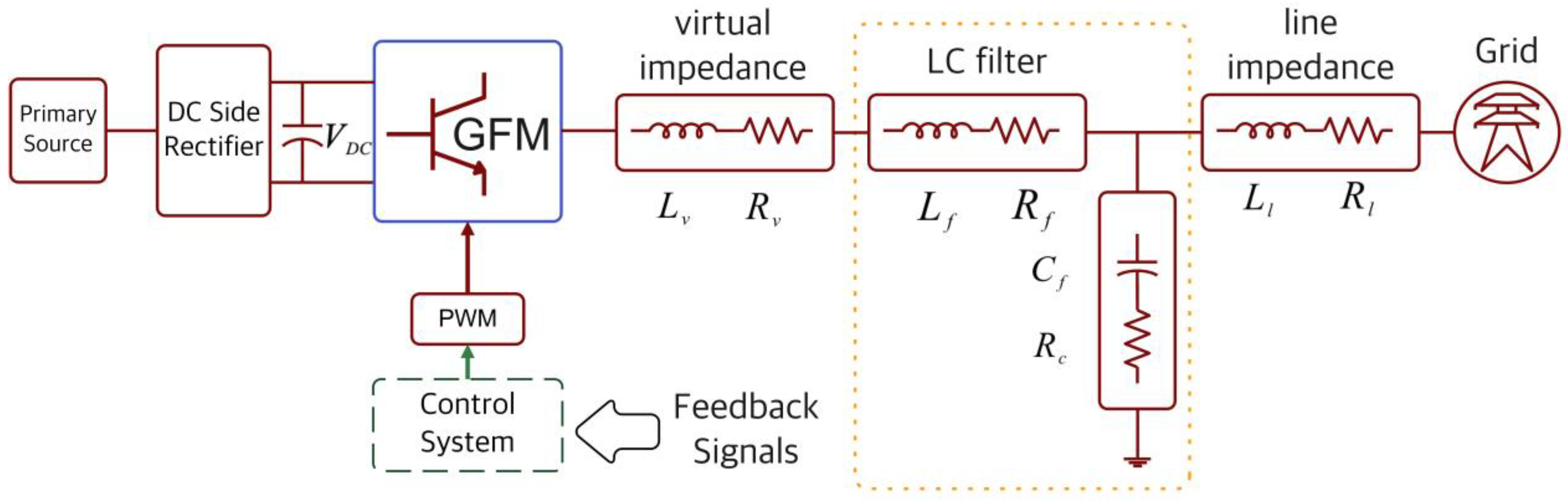
1.1. Grid-Forming Converter

GFM converters have emerged as an important foundation of the future power system, addressing the challenges raised by the increasing integration of the RESs. Unlike conventional synchronous machines (SMs), which inherently provide inertia and robust synchronization, the GFM converters should actively provide these functionalities through advanced control strategies. This necessity arises from the smooth transition to low-inertia power systems, where the loss of SMs and their associated frequency and voltage regulation mechanisms creates significant stability challenges [2].
One of the primary advantages of the GFM converters is their ability to mimic the SMs’ behavior, thereby stabilizing frequency and voltage while ensuring a reliable grid operation. Various control methodologies have been developed to achieve these objectives, including virtual synchronous machine (VSM) control, droop control, power synchronization control, and virtual oscillator control. These methods differ in their underlying principles, target applications, and performance under different operating conditions, but they all try to enhance the dynamic performance and grid-support capabilities of the GFM converters. Ref. [4] discusses the interaction among grid-connected converters and their control philosophies. It introduces the component connection method technique for obtaining state-space representations of complex systems. μ-analysis is used to assess converter robustness under different operating conditions.
In ref. [5], the authors examine the control architecture of the GFL and GFM converters’ control systems. Furthermore, a case study is presented to assess the efficacy of two control mechanisms in response to frequency disruptions. A simulation model of a 15 KW grid-connected converter is constructed in Matlab/Simulink to analyze the performance of GFL and GFM converters under various operating situations. Moreover, Ref. [6] reviews and compares five major general frequency control strategies in the GFM converters: droop control, synchronverter, matching control, VOC, and IoT/ICT-based approaches. It critically evaluates performance and robustness using a simulation case study and identifies challenges.
Furthermore, Ref. [7] emphasizes the beneficial effects of the GFM converters on the frequency stability of the SMs. It presents a qualitative analysis that clarifies the frequency stability of the system, examines the behavior of the GFM converter controls under DC and AC current limitations, shows the significance of DC dynamics in the GFM converter control design, and highlights the necessity for an efficient AC current limitation scheme. Lastly, it analyzes the conditions in which the interaction between fast GFM converters and slow SM dynamics may lead to system instability. Ref. [8] investigates existing GFM control methods for the RES-dominated power grids, comparing their structure, grid support capability, fault current limiting, and stability. It provides a transient stability analysis, explores typical applications like AC microgrids and offshore wind farm integration systems, and discusses future challenges for GFM converters.
In addition, the fault ride-through (FRT) capability and current-limiting mechanisms of the GFM converters have achieved considerable attention. Conventional approaches often switch to the GFL converters’ control during faults, which weakens the voltage-mode operation essential for the GFM behavior. Advanced control designs have been proposed to maintain the GFMs’ voltage-mode characteristics while limiting fault currents to permissible levels, ensuring system stability under fault conditions [2,9].
In addition, the GFM converters also play a pivotal role in RES integration, especially in applications such as modern power grids, offshore wind farms, and interconnected transmission networks. For instance, they have demonstrated their capacity to support the frequency stability of the SMs in hybrid systems and to address DC-side voltage collapse issues during large disturbances [7,10,11]. These features are critical in scenarios where the AC and DC dynamics of the grid are tightly coupled and require coordinated control strategies.
Despite the progress in GFM technologies, significant challenges remain. Large-signal stability analysis, for example, is an area that requires further exploration, as most existing studies focus on small-signal stability. The interaction between fast GFM dynamics and slower SM dynamics also introduces potential stability concerns that need to be addressed through innovative control solutions. These challenges are investigated in [4,5]. Furthermore, a unified framework integrating multivariable feedback control has shown promise in optimizing the performance of the GFM converters across a wide range of applications, from islanded modern power grids to large-scale RESs [8,11].
In the future, research efforts should be focused on enhancing the robustness, adaptability, and scalability of the GFM converters’ control strategies. The incorporation of advanced algorithms, such as structured synthesis and disturbance observer frameworks, offers solutions to overcome limitations in traditional control approaches. Additionally, smooth transitions between the GFM and GFL operation modes, improved fault tolerance, and better interaction with hybrid systems will be critical to unlocking the full potential of GFMs in supporting a resilient and sustainable energy system [6,12,13,14,15,16,17].
Ref. [12] explores the GFM control system in low-inertia power systems, focusing on the SM model. It proposes a new converter control strategy based on an internal rotating magnetic field. The system is augmented with a virtual oscillator, ensuring exact matching between the converter and SM dynamics. The study also uses disturbance-decoupling and droop techniques to design additional control loops. Moreover, Ref. [13] provides an overview of control schemes for the GFM converters, analyzing different solutions for each subsystem. It discusses open issues and challenges, such as angle stability, fault ride-through capabilities, and transition between islanded to grid-connected modes, and shares perspectives on challenges and future trends in GFM converters.
Ref. [14] proposes a generalized GFM converter architecture using multivariable feedback control, combining various control strategies into a transfer matrix. This configuration considers AC and DC control, active power, and reactive power, providing better performance. A new multi-input–multi-output-based GFM converter control is proposed, and an optimal H synthesis is used to design control parameters. Moreover, Ref. [15] analyzes control strategies for the GFM converters considering power grid stability, including frequency droop control, virtual synchronous machine control, and dispatchable virtual oscillator control. The proposed control methods address DC-side voltage collapse and ensure grid connection synchronization.
Additionally, Ref. [16] examines the GFM converters in microgrid applications and their potential use in large-scale networks with the RESs. It highlights the importance of GFMs’ ability to withstand system disturbances and their role in establishing a sustainable energy system. The study provides a comprehensive classification of control objectives and applications, emphasizing their importance and effectiveness. The findings are applicable to various interdisciplinary fields, including power system operation, power electronics, renewable energy integration, advanced control, and smart grids. Finally, Ref. [17] proposed a GFM converter control method for grid converters that uses a disturbance observer structure and offers multiple control modes. It does not require a separate synchronization loop and provides tuning recommendations. The method’s robustness against inductance error is demonstrated through experiments with a 12.5 kVA converter.
With rapid advancements in artificial intelligence (AI), data-driven approaches have emerged as a vital and transformative tool in addressing complex engineering challenges. The current level of AI capabilities emphasizes the significance of using data to optimize, adapt, and innovate in various domains, including power systems. Methods based on data-driven techniques offer unique advantages, such as adaptability, scalability, and the ability to handle nonlinear and dynamic behaviors, making them an important research area. The integration of these methods into power systems, particularly for control and tuning applications, represents a promising direction for enhancing system performance and reliability in the face of evolving grid demands and RES penetration, which will be investigated in the next subsection.

1.2. Data-Driven and Neural Network-Based Tuning Methods

The growing complexity of modern power grids, driven by the integration of RESs and distributed energy resources (DERs), has emphasized the need for advanced control methods. Traditional control strategies, often based on classical linear approaches, face limitations in terms of adaptability, robustness, and real-time performance. Recent research works highlight the transformative potential of data-driven and neural network-based (NN-based) tuning methods in addressing these challenges. These approaches use the wide amount of data generated by modern grid systems and utilize AI techniques to optimize control performance, enhance system stability, and ensure efficient operation.
Indeed, data-driven control methodologies offer flexibility and adaptability by relying on system data rather than precise mathematical models. Studies such as refs. [18,19,20] demonstrate the utility of data-driven methods for modeling and control in modern power grids, providing reliable alternatives to conventional techniques. The NNs, as highlighted in refs. [21,22] are increasingly employed to adaptively tune controller parameters, enabling systems to respond dynamically to time-varying conditions and disturbances. The incorporation of machine learning, including supervised, unsupervised, and reinforcement learning paradigms, has proven effective in designing controllers that outperform traditional methods in both dynamic and steady-state scenarios [23,24,25,26].
For grid-connected converters (GCCs), the NNs have been applied to enhance performance by addressing the shortcomings of conventional proportional-integral (PI) controllers. Refs. [27,28] illustrate the effectiveness of NN-based controllers, such as data-driven online learning (DDOL) and proportional integral NNs (PINNs), in improving dynamic and steady-state responses. Similarly, ref. [21] employs convolutional NNs (CNNs) to achieve rapid and accurate parameter adjustments in converters operating under variable grid conditions, further demonstrating the adaptability and computational efficiency of NN in real-time scenarios.
In modern power grids, the NN-based active disturbance rejection control has shown promise for regulating output voltage under various operating conditions [24]. The NN not only ensures rapid response but also reduces the reliance on traditional sensors, optimizing the control process. Advanced reinforcement learning techniques, such as multi-agent deep reinforcement learning, have been explored to achieve decentralized control objectives in modular converters [24], offering scalable solutions for complex grid configurations.
Despite these advancements, the existing applications of NNs often focus on isolated aspects of control systems, such as parameter tuning or modeling for specific loops. For instance, ref. [29] uses transfer learning to characterize converter impedance patterns, while [30] introduces data-driven adaptive control for voltage regulation in variable-inertia modern power grids. However, these methods have not been fully explored for tuning the control parameters of the GFM converters, a critical component in ensuring system stability and resilience in modern power grids. Moreover, Ref. [31] presents a nonlinear controller designed to stabilize dc/dc full-bridge converters in telecom power applications. The controller uses a soft actor–critic algorithm with deep neural networks based on deep reinforcement learning to optimize controller parameters. A reward signal is defined for training the neural networks, and an efficient solution is tested using the OPAL-RT 5600. While this research work used a robust-based neural network method, designing a nonlinear controller could impose high costs and complexity on the implementation of this idea. That is why it is important to consider methods that are simpler and cheaper to be easily implemented in the industry. Furthermore, Ref. [32] developed a backstepping control strategy to control a nine-level packed electric cell rectifier for smart electric vehicle charging. Proximal policy optimization with deep neural networks is used to adjust the controller, allowing the rectifier to handle asymmetrical/symmetrical dc loads. This method used a higher number of hidden layers and also a more complex neural network strategy to implement the proposed method.
This gap emphasizes the need for research into the application of robust NNs for tuning existing control structures in the GFM converters. By integrating the NN-based tuning methods into the control system of these converters, it is possible to optimize their performance under diverse operating conditions, enhance robustness against system uncertainties, and address the dynamic challenges introduced by the increasing penetration of the RESs.

1.3. Research Gaps and Challenges

The integration of data-driven and NN-based tuning methods into modern power grids has demonstrated significant advancements in optimizing control strategies for the GCCs. However, critical gaps remain that prevent the comprehensive application of these methods, particularly in the GFM converter control systems, which play a pivotal role in modern power grids. The existing research works generally focus on enhancing the performance of isolated control loops, parameter tuning under specific scenarios, or developing new models for classical controllers. For example, while CNNs and reinforcement learning have been employed for adaptive parameter adjustments in converters, these approaches have not been systematically extended to the complex control structures of the GFM converters and robust control concepts.
Moreover, the current advance in data-driven methodologies often emphasizes local or modular control objectives without addressing the wider implications of integrating such techniques into the hierarchical control structure of the GFM converters’ control systems. Challenges insist on adapting the robust NNs to handle the multi-layered, nonlinear dynamics of these systems, especially under varying grid conditions and high penetration of the RESs.
Another notable gap is the lack of frameworks that combine real-time adaptability with stability assurance for the GFM converters. While data-driven adaptive control strategies show potential, ensuring stability and maintaining optimal performance under uncertain and dynamic conditions remain open research challenges. Furthermore, there is insufficient exploration of hybrid approaches that integrate robust NNs with traditional methods, which could enhance system interpretability and robustness.

1.4. Objectives and Contributions

This paper aims to address the aforementioned gaps by investigating the application of robust artificial NNs (RANNs) to tune the existing control system parameters of the GFM converters in modern power grids. Specifically, this study seeks to enhance the dynamic performance, robustness, and adaptability of these converters, ensuring reliable operation under diverse grid conditions and high penetration of RESs.
The primary objectives of the present research work are as follows:
Developing a comprehensive framework for integrating the RANN-based tuning methods into the existing control structures of the GFM converters.
Investigating the potential of NNs in improving the transient and steady-state performance of the GFM converters, particularly in response to variations in grid inertia, load demand, and renewable energy fluctuations.
The main contributions of this work include the following:
A novel RANN-based stabilizing tuning framework: proposing a systematic approach for embedding the RANNs into the GFM converter control loops, enabling the dynamic and adaptive tuning of control parameters.
Enhanced control performance: demonstrating improved transient response, steady-state accuracy, and robustness against system uncertainties compared to traditional controllers.
By addressing these objectives and contributions, this research aims to establish a foundation for advancing the control systems of the GFM converters, opening the way for their reliable integration into future modern power grids. The rest of the paper is organized as follows: Section 2 presents system modeling and problem formulation. The proposed robust neural network-based tuning framework is addressed in Section 3. Section 4 explains simulation and HIL-based real-time results. A comprehensive discussion is given in Section 5, and finally, conclusions and future work are presented in Section 6.

2. System Modeling and Problem Formulation

As mentioned earlier, the penetration rate of GCC-based DGs in a modern power grid is rapidly expanding because of the successive rise in power generation using RESs such as photovoltaics and wind turbines. Unlike traditional centralized power generation systems that rely on SMs, GCC-based DGs lack a rotating mass to contribute inertia support to the electrical grid.
As a result, increasing the number of GCCs presents grid operators with the problem of insufficient inertia, which inherently causes a high rate of change of frequency (RoCoF) in the grid. Increased frequency deviations can lead to reliability problems, such as loads and equipment in the electrical grid being tripped due to frequency instability. Consequently, the electrical grid is experiencing significant fluctuations in frequency, leading to a decline in performance. Therefore, it is necessary to reconfigure the control design of these systems [1].
Authors in ref. [1] (chapter 3) explained a state-space modeling method used to analyze the behavior of a GFM converter in terms of active power and frequency management. The control system of a GFM converter is presumed to have the ability to replicate desired dynamics, including virtual inertia, droop loop, and damping characteristics. For modeling purposes, a typical GFM converter control scheme is depicted in Figure 1.
The introduced model’s validity is proven through step response assessments using simulation and experimental findings, hence confirming the accuracy of the proposed modeling method [1]. To create a model, a typical GFM converter with its control system is used. The control structure selected to govern active power and frequency is illustrated in Figure 2. The voltage drops over virtual inductance L v is generated to adjust the equivalent output reactance X of the inverter as shown in Equation (1).
X = ω 0 L v + L f + L l
where L f and L l are the GFM output filter and connecting line inductances. Equation (1) shows the amount of inductance part of the impedance between the GFM converter and the grid. This is useful to check if the network is inductive or not.
The control system block diagram shown in Figure 2 can be mathematically translated to Equation (2). It represents that the GFM converter active power can be decomposed into three terms including virtual inertia, virtual droop, and virtual damping characteristics. These fully emulate the dynamics of an SM.
P 0 P o u t = J ω 0 d ω m d t + k p ω m ω 0 + D ω m ω g ˜
Here, P 0 is the active power reference, D is the damping factor, k p is the droop coefficient,   ω m is the generated virtual frequency, ω 0 is the nominal frequency, P o u t shows the output power, and J represents the moment of inertia. The grid frequency ω g cannot be measured easily; therefore, it is estimated by ω ^ g , which is the angular frequency measured by a phase-locked loop (PLL) from output voltage V o u t , as shown in Figure 2.
Here, the aim is to obtain a dynamic model to study the active power-frequency response of a GFM converter. In the literature, assuming the grid is sufficiently stiff, a GFM converter with the grid is typically seen as a single DG connected to an infinite bus system. In this condition, as the point of common coupling (PCC) voltage is calculated using the grid voltage, ω g could be considered as a disturbance from the grid side [1]. It is well known that the synchronizing power coefficient K of the DG can be expressed as
K = P o u t δ E V g c o s δ 0 X V b a s e 2 1 X * 2 X
where
X * = X S b a s e / V b a s e 2
δ is the power angle, and δ 0 is its operating point. The derivative of the power angle can be represented as
d δ d t = ω m ω g
Here, E is the electromotive force, V g is the voltage of the grid bus, V b a s e is the rated voltage, S b a s e is the rated power, and X * is the per unit value of output reactance X .
Hence, the small-signal state-space model for the GFM converter can be derived using Equations (6) to (7). The variables x, u, and y represent the system states, control input, and outputs, respectively [1].
x ˙ = A x + B u y = C x
where
x = Δ ω m Δ P o u t Δ x 1 p l l Δ x 2 p l l , A = k p J ω 0 1 J ω 0 D K p , p l l * J D J ω 0 T i , p l l K 0 0 0 0 0 ω 0 K p , p l l * 1 T i , p l l 0 0 ω 0 K p , p l l * 0 ,   B = 1 J ω 0 0 0 0 , C = I 2 0 2 × 2
Here, Δ x 1 P L L and Δ x 2 P L L represent the PLL state variables ( V g q and V g q ) . Furthermore, K p * P L L and T i P L L show the proportion and time constant of the integrator of the PI controller (in the PLL structure).

3. Robust Neural Network-Based Tuning Framework

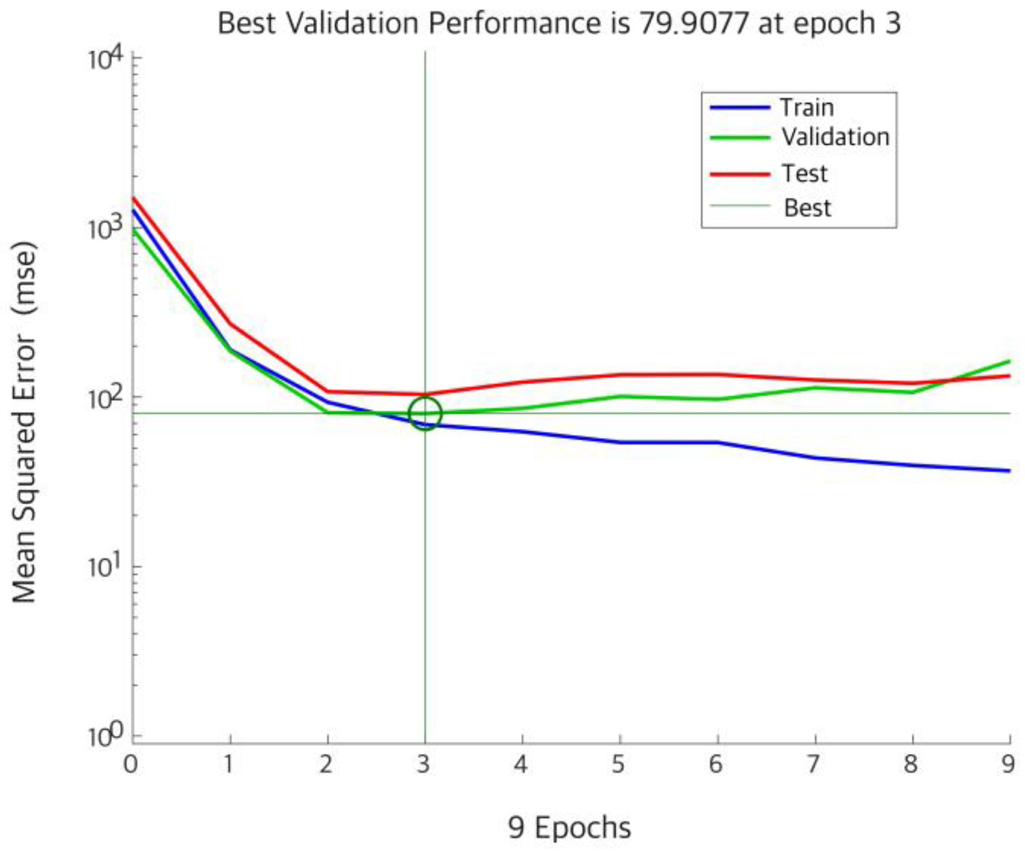
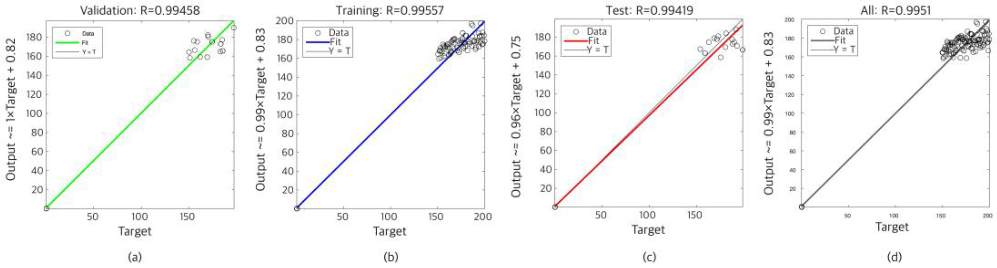
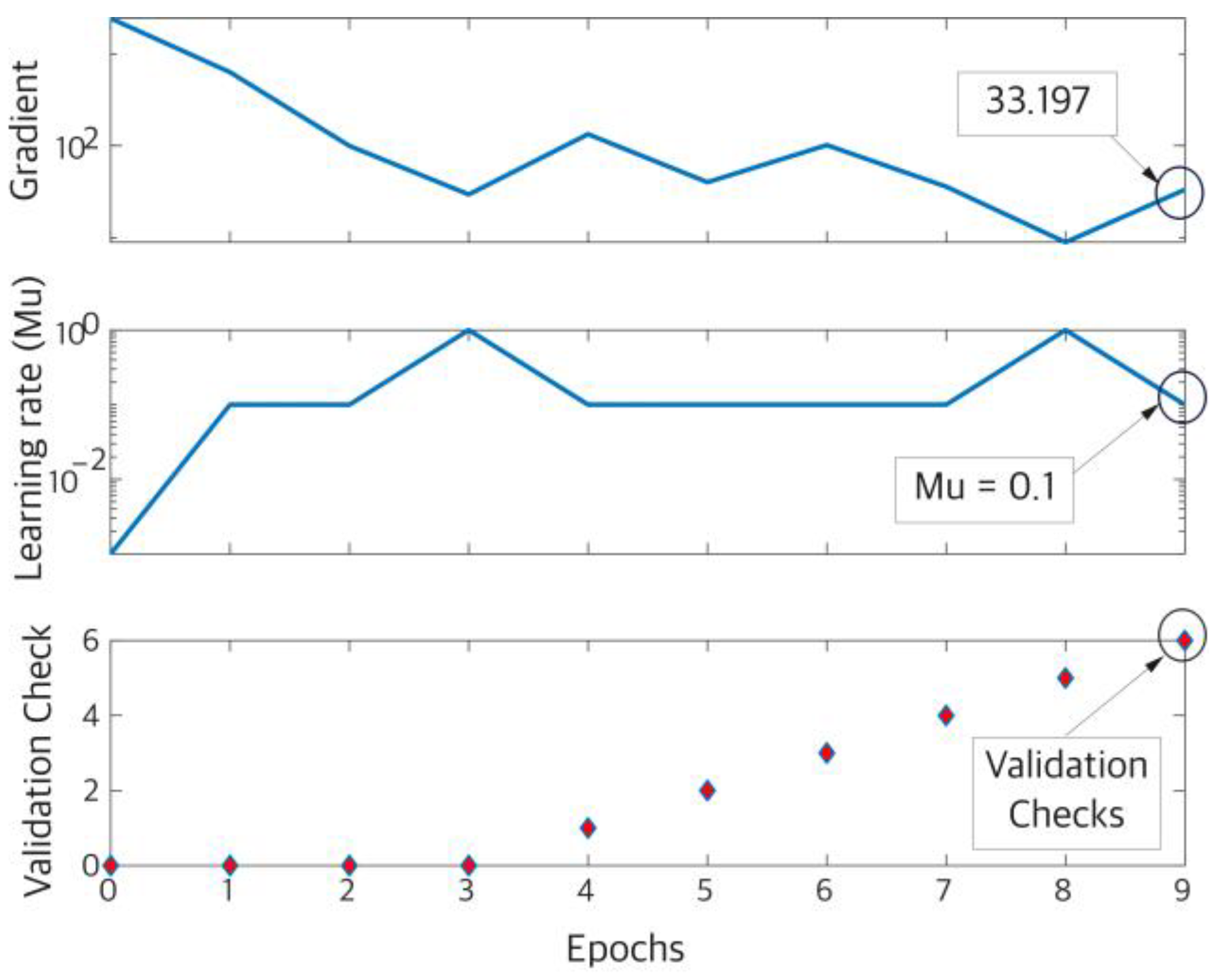
3.1. Neural Network Architecture and Training Strategy

The RANN is designed to adaptively tune system parameters in real time, ensuring stability and optimal performance under varying operating conditions. The network architecture comprises three layers: an input layer, a hidden layer with adaptive weights, and an output layer that adjusts critical system parameters such as damping coefficient D and moment of inertia J.
The input layer processes normalized system states and error signals. Considering x t represents the vector of system states, and d t represents disturbances, the input vector to the network is defined as
u t   =   x t ,   e t ,   d t T
where e t is the error signal between the desired output y d t and the actual system output y t :
e t   =   y d t     y t
The parameters of the above-mentioned case study are given in Table 1.
The hidden layer uses radial basis function (RBF) activations to model nonlinear mappings. The output of the hidden layer is given by
h i t = ϕ w i T u t + b i
where w i are the weights, b i   are biases, and ϕ   is the activation function.
The output layer maps the hidden layer activations to the system parameters:
y N N t = W o h t
where W o   represents the output layer weights. The outputs y N N t correspond to the dynamically tuned parameters D t and   J t .
The network considers offline pretraining using a dataset generated from simulations:
L pretrain   =   1 N   i = 1 N   | y N N t i     y true t i | 2
where y true t   represents the target values of D and J . After this step, the weights are updated online using adaptive learning laws to minimize real-time errors.

3.2. Robust Neural Network

The robust NN is an important part of the adaptive control strategy, designed to ensure both real-time adaptability and long-term stability of the system. To achieve this, the network employs advanced weight update mechanisms that allow for dynamic adjustments to system parameters in response to changing conditions, nonlinearities, and external disturbances. These mechanisms not only enhance the network’s ability to react quickly but also prevent instability and performance degradation during continuous operation. Two primary techniques are employed to achieve these goals, each addressing specific challenges associated with online learning and parameter adaptation [22,32].

3.2.1. Deadzone Technique

The deadzone technique introduces a threshold for error-based updates, effectively filtering out noise and minor disturbances that do not warrant significant changes in the system’s behavior. This technique ensures that weight updates occur only when the system error exceeds a predefined threshold, denoted as ϵ . Mathematically, the weight adaptation law is expressed as [32]
w ˙ = β Γ T e t ,   i f   e t > ϵ   0 ,   t h e r w i s e    
where w ˙   represents the rate of change in the network weights, β is the learning rate that controls the speed of adaptation, Γ denotes the NNs basis functions or feature representations, and e t is the system error. The threshold ϵ prevents the network from making unnecessary updates in the presence of noise, thus avoiding weight oscillations and ensuring stability. This selective adaptation mechanism is particularly beneficial in environments with high-frequency noise or when minor fluctuations in system performance are tolerable [32].

3.2.2. E-Modification Technique

The e-modification technique incorporates a regularization term into the weight update rule to prevent weight drift and ensure long-term stability. Unlike the deadzone technique, which focuses on suppressing noise-induced updates, the e-modification technique adds a damping term to the weight dynamics to limit excessive changes during persistent disturbances or long-time operations. The weight adaptation law in this method is given by [32]
w ˙ = β Γ T e t ν w w
where ν is the regularization coefficient that controls the magnitude of the damping effect, and w represents the norm of the weight vector. By penalizing large weight magnitudes, the e-modification technique ensures that the network remains robust to external disturbances while maintaining the boundedness of the weight updates. This mechanism is particularly effective in scenarios where continuous disturbances or sudden parameter shifts might otherwise lead to instability or unbounded weight growth [32].
Together, the deadzone and e-modification techniques enable the robust NN to balance rapid adaptability with inherent stability. The deadzone approach focuses on precision by ignoring trivial errors, ensuring that the network adapts only, when necessary, while the e-modification technique ensures robustness by preventing the weights from diverging under sustained disturbances. These complementary mechanisms make the robust NN a powerful tool for real-time adaptive control in highly dynamic and uncertain environments such as RES-based systems [32].

3.3. Input Features and Output Parameters

The input to the NN consists of system states, disturbances, and error signals. Specifically, the input vector can be expressed as
u t = ω t , θ t , e t , d t T
where ω t is the angular velocity, θ t is the position error, e t is the system error, and d t represents external disturbances.
The outputs of the network are the dynamically tuned damping coefficient D and moment of inertia J :
y N N t = D t , J t T
These parameters are constrained within physically meaningful ranges to ensure stability:
D min D t D max , J min J t J max
For example, 150 J t 200 and 0.2 D t 0.35 in this study.

3.4. Performance Metrics

The performance of the robust NN is evaluated using several key metrics. The steady-state error (SSE) is a measure of the long-term deviation of the system output from the desired value:
SSE = l i m t y d t y t
A well-tuned NN achieves a near-zero SSE under various operating conditions. The settling time ( T s ) quantifies how quickly the system output reaches and remains within a specified error margin (e.g., ±2%) of the steady-state value. The robust NN significantly reduces T s compared to static controllers. The overshoot ( M p ) is defined as the maximum deviation of the system output from the steady-state value during transient conditions:
M p = max t y t y d t
Minimizing M p ensures smooth transitions and prevents instability. The system’s stability is analyzed through eigenvalue placement:
λ i A   for   i = 1 , , n
where λ i A represents the eigenvalues of the closed-loop system matrix. Robust tuning ensures that all eigenvalues are in the left-half plane, with sufficient damping:
Re λ i < 0 , Im λ i Re λ i < 1
Figure 3 illustrates the tuning process and summarizes the relationship between the proposed RANN-based tuning method and the GFM converter.

4. Simulation and HIL-Based Real-Time Results

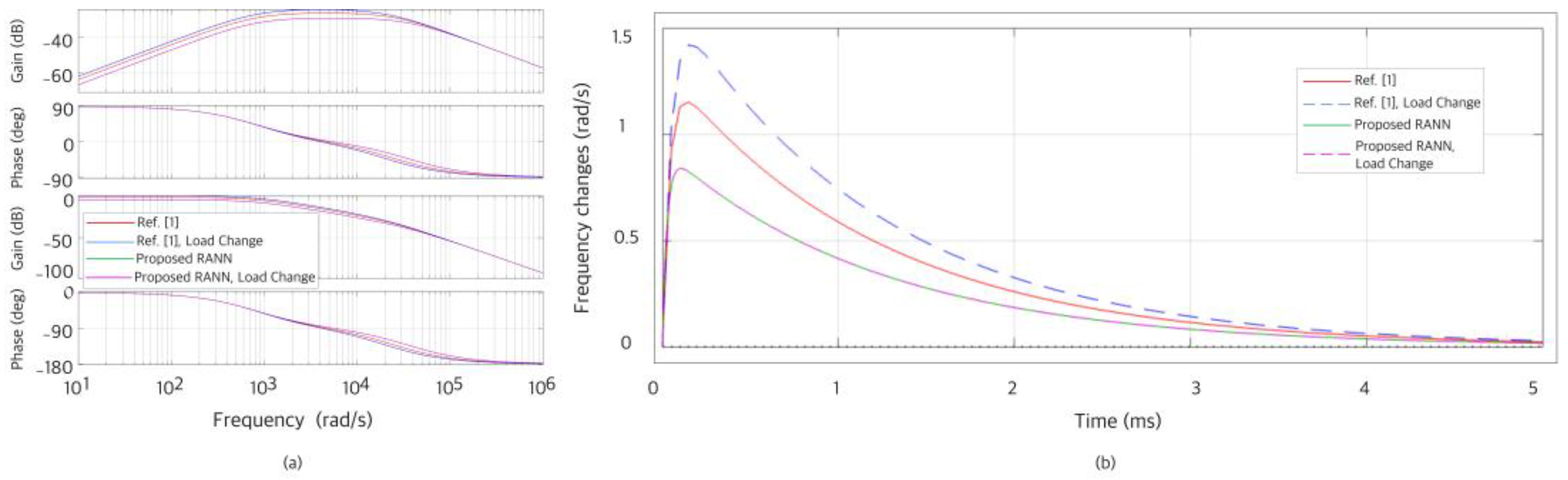
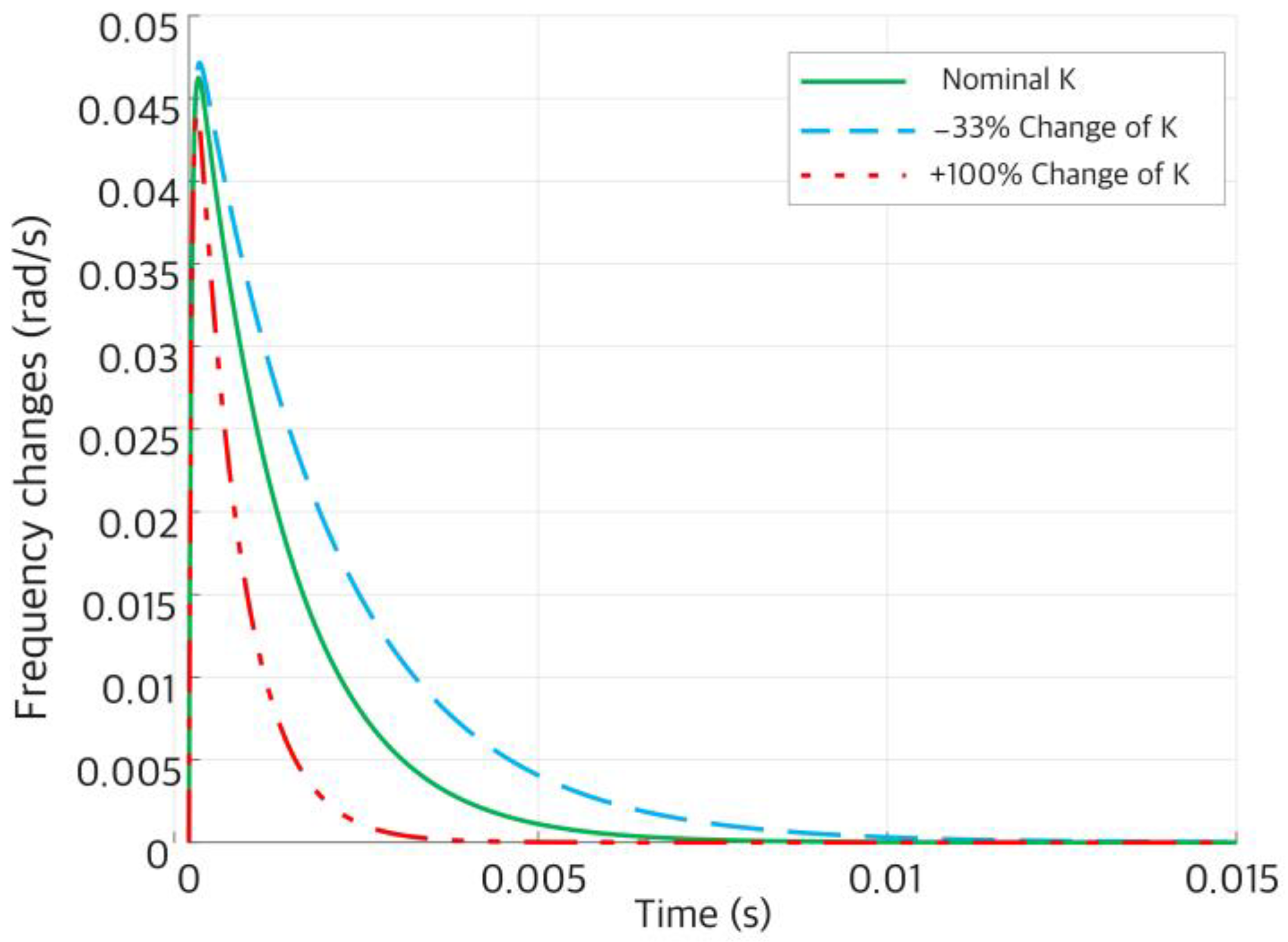
4.1. Simulation Results

In this section, the results of simulations and laboratory HIL-based real-time experimental tests are presented. All simulations were conducted in the MATLAB environment to evaluate system performance under various scenarios. First, the analysis of the NN is presented, and then, the test of the case study using the proposed RANN is investigated.
The error histogram shown in Figure 4 demonstrates the robust NN’s accuracy and generalization capabilities.
Most errors are concentrated near zero, indicating high predictive accuracy and minimal deviation from target values. The symmetric distribution around zero suggests that the model does not exhibit bias toward over- or under-prediction. The comparable distributions across training, validation, and test datasets highlight the model’s ability to generalize effectively to unseen data, avoiding overfitting. In addition, the majority of errors fall within the range [−5, 5], with only a few outliers beyond [−15, 15]. These outliers likely represent challenging data points or regions where the model’s approximation may require further refinement.
The performance plot, shown in Figure 5, illustrates the evolution of the mean squared error (MSE) across training, validation, and test datasets during the NN training process. It evaluates how well the NN learns the mapping between inputs and targets while ensuring that the model generalizes effectively to unseen data. The training process is completed over nine epochs, with the best validation performance of 79.9077 achieved at epoch 3. After this point, the validation error did not improve significantly, indicating that the network reached its optimal point early in the training process. The close alignment between the training and validation curves suggests that the network avoided overfitting, maintaining a consistent performance on unseen data. In addition, the test set error remains comparable to the validation set error, further confirming the model’s generalization capability. The gradual reduction in the training error over successive epochs highlights the network’s effective learning process, as it minimizes the MSE by adjusting its weights and biases.
Despite the early convergence, the relatively high MSE values (the best validation error being 79.9077) suggest that while the network captures the general relationships in the data, there may still be room for improvement. Potential enhancements could include refining the network architecture, increasing the size or diversity of the training dataset, or incorporating advanced optimization techniques to achieve lower error rates.
Figure 6 evaluates the relationship between the NNs’ predicted outputs and the target values for training, validation, and test datasets. It provides a quantitative and visual assessment of the model’s accuracy and generalization capability. Figure 6a exhibits a similarly high correlation coefficient, indicating that the network generalizes well to unseen data during the training process. The alignment of data points with the line reflects the network’s ability to maintain accuracy on validation data, minimizing overfitting. Figure 6b shows the high correlation coefficient indicates a strong linear relationship between the network’s outputs and the target values during training. The data points align closely with the diagonal line, showing that the network learned the mapping effectively and captured the underlying patterns in the training data. Figure 6c demonstrates the network performance on completely unseen data. The correlation coefficient is slightly lower than that for training and validation, which is expected, but it remains high. This consistency across datasets highlights the robustness of the NN. Figure 6d shows the combined regression plot for all datasets, confirming the model’s strong overall performance. The majority of the data points closely follow the diagonal line, with minimal deviation, demonstrating the network’s reliability across the full dataset.
As shown in Figure 7, a detailed view of key metrics during the training process of the NN over nine epochs is investigated. It shows the network’s optimization behavior, convergence characteristics, and generalization performance. The gradient plot (top panel) shows the magnitude of the gradient of the loss function concerning the network’s weights and biases. The gradient starts at a relatively high value and decreases steadily over successive epochs, indicating that the network is learning effectively by minimizing the error. At epoch 9, the gradient stabilizes at 33.197, suggesting convergence toward an optimal solution. The gradual reduction in gradient magnitude reflects the effectiveness of the optimization process, ensuring that the network achieves a balance between accuracy and stability.
The middle panel tracks the adaptive learning rate parameter used in the Levenberg–Marquardt optimization algorithm. Initially, increases to facilitate rapid exploration of the parameter space reach a peak value of 0.1. Afterward, fluctuates within a controlled range, indicates that the optimizer transitions from coarse adjustments to fine-tuning as it approaches convergence. The stabilization toward the end of training suggests that the optimization process successfully balances local and global adjustments to minimize the loss function. Finally, the validation checks plot (bottom panel) shows the number of consecutive epochs during which the validation error fails to improve. At epoch 9, the training process records six validation checks, indicating that the network’s performance on the validation dataset stopped improving. This is the maximum allowable number of validation checks, and it triggers the early stopping criterion to prevent overfitting. This behavior demonstrates that the training process adheres to regularization principles, ensuring that the network does not overfit the training data while maintaining generalization capability.
Figure 8a presents the Bode diagram comparison of the closed-loop systems between the proposed RANN method and the reference system [1]. The magnitude plot shows that the RANN closely matches the reference system under nominal conditions and maintains stability during load changes. The phase plot indicates minimal phase deviation under nominal conditions, with enhanced stability during load changes and reduced oscillations at higher frequencies.
The system step response, as shown in Figure 8b, highlights transient and steady-state performance. The plot shows the frequency response; the reference system exhibits a larger overshoot and slower settling time, particularly under load change conditions, as seen from the dashed blue curve. The value of applied load change was equivalent to about 0.1 pu load step decrease. The proposed RANN significantly reduces overshoot and settling time under both nominal and load change conditions, demonstrating better transient performance.
The closed-loop system step response in the presence of parametric uncertainty is examined by −33% and +100% perturbation in the synchronization parameter (K). The result is depicted in Figure 9.

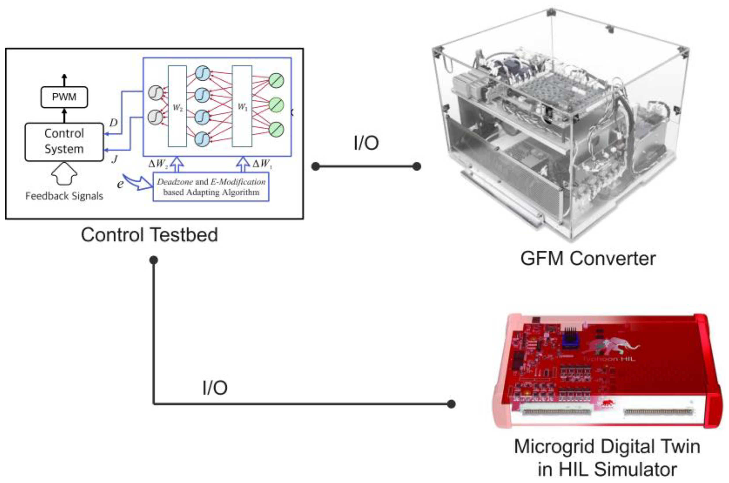
4.2. Laboratory Real-Time Results

The HIL devices are crucial elements in the testing practices of GFM converters. They enable the integration of actual hardware components with computer simulations, facilitating the evaluation of complex system performance and functionality. The HIL technology typically comprises a physical hardware unit, such as a controller or sensor, which is linked to a simulation environment. Within this environment, virtual inputs and exciters are generated and fed into the HIL device for processing [33]. The device responds as if it were connected to the real system, enabling engineers to analyze the system behavior under diverse operational circumstances. Figure 10 shows the role of HIL devices in the GFM converter test case study. The I/O represents the input/output channels.
Figure 11 displays real-time laboratory results acquired by Typhoon Hardware-in-Loop (HIL) to assess the efficacy of the proposed technique. Figure 11a shows the frequency dynamic response of the system during a transient event, with oscillations observed initially before stabilizing at approximately 60 Hz. This demonstrates the system’s frequency regulation capability under disturbance. Figure 11b illustrates the active power at the PCC, which indicates a rapid increase during the transient event, stabilizing near 700 kW. This highlights the system’s ability to manage power flow effectively during dynamic conditions. Figure 11c shows the HIL configuration setups. This setup validates the performance of the proposed control system under realistic conditions using HIL experimental setups, enabling the reliable evaluation of transient responses and system stability.

5. Discussion

The results presented in this study demonstrate the effectiveness of the proposed RANN framework for tuning the damping coefficient and moment of inertia in GFM converters. Compared to traditional methods, such as fixed parameter tuning or conventional control approaches, the RANN exhibited superior adaptability and stability under varying operating conditions. The proposed method achieved faster settling time, reduced steady-state error, and enhanced robustness against external disturbances, as evidenced by the step response, eigenvalue placement, and frequency-domain analyses.
The employed case study, controller structure, and closed-loop system are the same as the ones used in Ref. [1]. The stability analysis of the given control system is well discussed in the mentioned reference. In the present work, the focus is on the optimal tuning of two control parameters (virtual inertia and virtual damping coefficients) among a prespecified safe (stabilized) range. As shown in inequalities (17), the parameters are constrained within a range to ensure stability. Therefore, the present problem is an optimal performance regulation one rather than a stabilizing control one.
However, the proposed method is not without limitations. One significant challenge lies in the increased computational complexity associated with real-time NN adaptation. While the network performance is robust, the online weight adjustment process can introduce additional computational overhead, particularly in systems with constrained hardware resources. Furthermore, the pretraining phase of the NN relies on simulated and HIL data, which, if not representative of the full range of operating conditions, may impact the network’s initial performance during deployment. Another limitation is the sensitivity of the ANN to the choice of hyperparameters, such as the learning rate and regularization terms, which can influence the balance between adaptability and stability. Careful tuning of these parameters is necessary to avoid instability or suboptimal performance.
Lastly, while the proposed RANN demonstrates clear advantages in tuning D and J , its application is currently limited to specific scenarios in GFM converters. Extending this approach to other types of converters, such as dual GFM-GFL converters or a condition to tune more parameters, may require additional modifications to account for differing dynamics and control objectives. Despite these challenges, the results strongly suggest that the RANN is a promising tool for advanced control applications, with the potential for further refinement and wider applicability. In addition, this work could be a proper point to improve the challenges of this approach in future research.
To better illustrate the strengths and limitations of the proposed method in comparison to other advanced control approaches, Table 2 provides a detailed summary. The table compares the proposed RANN-based smart tuning approach with a nonlinear data-driven method (Ref. [32]) and a deep reinforcement learning approach (Ref. [31]), focusing on their advantages and disadvantages.

6. Conclusions and Future Work

This paper introduced a RANN-based framework for tuning critical parameters of GFM converters, specifically the damping coefficient and moment of inertia. The proposed method was compared with traditional tuning approaches, demonstrating significant improvements in dynamic performance, robustness, and adaptability. By employing advanced weight updating mechanisms, such as the deadzone and e-modification techniques, the RANN successfully addressed challenges associated with system nonlinearities, external disturbances, and parameter variations. The results showed that the RANN achieved faster settling times, reduced overshoot, and better disturbance rejection compared to conventional methods. Experimental validation on HIL platforms confirmed the practical feasibility of the proposed method.
One of the key advantages of the RANN is its ability to dynamically adjust system parameters in real time, enabling the converter to maintain optimal performance across a range of scenarios. The incorporation of advanced weight updating mechanisms, such as the deadzone and e-modification techniques, ensures stability and avoids issues like weight drift or excessive oscillations during adaptation. Additionally, the network’s flexibility allows it to handle large parameter variations and external disturbances, which traditional fixed-parameter methods often struggle to manage effectively.
Despite these successes, several areas for improvement and future exploration remain. One key direction is the optimization of the ANN architecture to reduce computational overhead, making it more suitable for systems with limited hardware capabilities. Techniques such as pruning or quantization could be investigated to streamline the network while preserving its robustness and accuracy. Additionally, further work is needed to enhance the pretraining phase by incorporating data from a wider range of operating conditions, thereby improving the network’s initial performance and reducing the reliance on extensive online adaptation.
Another avenue for future research involves extending the RANN framework to other types of converters and power systems. For example, dual GFL-GFM converters, hybrid systems, or systems with high renewable energy penetration could benefit from the adaptive capabilities of the RANN. Addressing these challenges and exploring these opportunities will pave the way for more advanced and reliable control strategies in modern power grids.

Author Contributions

Conceptualization, S.R.; Methodology, S.R. and H.B.; Software, S.R.; Validation, S.R.; Formal analysis, S.R.; Investigation, S.R.; Resources, S.R.; Data curation, S.R.; Writing—original draft, S.R.; Writing—review and editing, S.R. and H.B.; Visualization, S.R.; Supervision, H.B., C.T.U., T.K. (Takeyoshi Kato) and T.K. (Toshiji Kato); Project administration, S.R. All authors have read and agreed to the published version of the manuscript.

Funding

This research received no external funding.

Data Availability Statement

No new data is created for this work.

Conflicts of Interest

The authors declare no conflict of interest.

References

  1. Bevrani, H.; Kato, T.; Ise, T.; Inoue, K. Grid Connected Converters: Modeling, Stability and Control; Elsevier: Amsterdam, The Netherlands, 2022. [Google Scholar]
  2. Lasseter, R.H. MicroGrids. In Proceedings of the 2002 IEEE Power Engineering Society Winter Meeting. Conference Proceedings (Cat. No.02CH37309), New York, NY, USA, 27–31 January 2002. [Google Scholar]
  3. Parhizi, S.; Lotfi, H.; Khodaei, A.; Bahramirad, S. State of the art in research on modern power grids: A review. IEEE Access 2015, 3, 890–925. [Google Scholar] [CrossRef]
  4. Rosso, R.; Engelken, S.; Liserre, M. Robust stability investigation of the interactions among grid-forming and grid-following converters. IEEE J. Emerg. Sel. Top. Power Electron. 2019, 8, 991–1003. [Google Scholar] [CrossRef]
  5. Gao, X.; Zhou, D.; Anvari-Moghaddam, A.; Blaabjerg, F. Grid-following and grid-forming control in power electronic based power systems: A comparative study. In Proceedings of the IECON 2021—47th Annual Conference of the IEEE Industrial Electronics Society, Toronto, ON, Canada, 13–16 October 2021. [Google Scholar]
  6. Tayyebi, A.; Dörfler, F.; Kupzog, F.; Miletic, Z.; Hribernik, W. Grid-Forming Converters–Inevitability, Control Strategies and Challenges in Future Grids Application, 2018, CIRED Workshop—Ljubljana. Available online: https://www.cired-repository.org/bitstream/handle/20.500.12455/1249/CIRED%202018%20Ljubljana%20WS%20-%200236%20-%2021086.pdf?sequence=1 (accessed on 10 January 2025).
  7. Tayyebi, A.; Groß, D.; Anta, A.; Kupzog, F.; Dörfler, F. Frequency stability of synchronous machines and grid-forming power converters. IEEE J. Emerg. Sel. Top. Power Electron. 2020, 8, 1004–1018. [Google Scholar] [CrossRef]
  8. Fu, X.; Sun, J.; Huang, M.; Tian, Z.; Yan, H.; Iu, H.H.C.; Hu, P.; Zha, X. Large-signal stability of grid-forming and grid-following controls in voltage source converter: A comparative study. IEEE Trans. Power Electron. 2020, 36, 7832–7840. [Google Scholar] [CrossRef]
  9. Taul, M.G.; Wang, X.; Davari, P.; Blaabjerg, F. Current limiting control with enhanced dynamics of grid-forming converters during fault conditions. IEEE J. Emerg. Sel. Top. Power Electron. 2019, 8, 1062–1073. [Google Scholar] [CrossRef]
  10. Khan, S.A.; Wang, M.; Su, W.; Liu, G.; Chaturvedi, S. Grid-forming converters for stability issues in future power grids. Energies 2022, 15, 4937. [Google Scholar] [CrossRef]
  11. Arghir, C.; Jouini, T.; Dörfler, F. Grid-forming control for power converters based on matching of synchronous machines. Automatica 2018, 95, 273–282. [Google Scholar] [CrossRef]
  12. Rosso, R.; Wang, X.; Liserre, M.; Lu, X.; Engelken, S. Grid-forming converters: An overview of control approaches and future trends. In Proceedings of the 2020 IEEE Energy Conversion Congress and Exposition (ECCE), Detroit, MI, USA, 11–15 October 2020. [Google Scholar]
  13. Chen, M.; Zhou, D.; Tayyebi, A.; Prieto-Araujo, E.; Dörfler, F.; Blaabjerg, F. Generalized multivariable grid-forming control design for power converters. IEEE Trans. Smart Grid 2022, 13, 2873–2885. [Google Scholar] [CrossRef]
  14. Gao, Y.; Ren, H.P.; Li, J. Grid-forming converters control based on dc voltage feedback. arXiv 2020, arXiv:2009.05759. [Google Scholar]
  15. Alshahrani, S.; Khan, K.; Abido, M.; Khalid, M. Grid-forming converter and stability aspects of renewable-based low-inertia power networks: Modern trends and challenges. Arab. J. Sci. Eng. 2024, 49, 6187–6216. [Google Scholar] [CrossRef]
  16. Nurminen, T.; Mourouvin, R.; Hinkkanen, M.; Kukkola, J. Multifunctional grid-forming converter control based on a disturbance observer. IEEE Trans. Power Electron. 2024, 39, 13023–13032. [Google Scholar] [CrossRef]
  17. Ning, K. Data driven artificial intelligence techniques in renewable energy system. Doctoral dissertation, Massachusetts Institute of Technology, Cambridge, MA, USA, 2021. [Google Scholar]
  18. Karimi, A.; Bahrani, B.; Zheng, D.; Madani, S.S. Data-Driven Control and Its Applications to Modern power grids. In Proceedings of the 2022 IEEE Conference on Control Technology and Applications (CCTA), Trieste, Italy, 23–25 August 2022. [Google Scholar]
  19. Soliman, A.S.; Amin, M.M.; El-Sousy, F.F.; Mohammad, O.A. A data-driven based online learning control of voltage source converter for DC modern power grids. In Proceedings of the 2021 IEEE International Conference on Environment and Electrical Engineering and 2021 IEEE Industrial and Commercial Power Systems Europe (EEEIC/I&CPS Europe), Bari, Italy, 7–10 September 2021. [Google Scholar]
  20. Issa, H.; Debusschere, V.; Garbuio, L.; Lalanda, P.; Hadjsaid, N. Artificial intelligence-based controller for grid-forming inverter-based generators. In Proceedings of the 2022 IEEE PES Innovative Smart Grid Technologies Conference Europe (ISGT-Europe), Novi Sad, Serbia, 10–12 October 2022. [Google Scholar]
  21. Li, Y.; Liao, Y.; Zhao, L.; Chen, M.; Wang, X.; Nordström, L.; Mittal, P.; Poor, H.V. Machine Learning at the Grid Edge: Data-Driven Impedance Models for Model-Free Inverters. IEEE Trans. Power Electron. 2024, 39, 10465–10481. [Google Scholar] [CrossRef]
  22. Silva-Vera, E.D.; Valdez-Resendiz, J.E.; Escobar, G.; Guillen, D.; Rosas-Caro, J.C.; Sosa, J.M. Data-Driven Modeling of DC–DC Power Converters. Electronics 2024, 13, 3890. [Google Scholar] [CrossRef]
  23. Qin, C.; Gao, F.; Zhou, K. Data-Driven Online Adaptive Parameters Adjustment for Output Quality of Grid-Connected Converters. In Proceedings of the IECON 2023—49th Annual Conference of the IEEE Industrial Electronics Society, Singapore, 16–19 October 2023. [Google Scholar]
  24. Bana, P.R.; Amin, M. Control for grid-connected VSC with improved damping based on physics-informed neural network. IEEE J. Emerg. Sel. Top. Ind. Electron. 2023, 4, 878–888. [Google Scholar] [CrossRef]
  25. Santos, L.E.; Bernardo, R.T.; Alcahuaman, H.; Ota, J.I.; Pomilio, J.A.; Dotta, D. An Online Data-Driven Tuning of Control Parameters for a Grid-Forming Inverter. In Proceedings of the 2022 IEEE Power & Energy Society General Meeting (PESGM), Denver, CO, USA, 17–21 July 2022. [Google Scholar]
  26. Pinthurat, W.; Kongsuk, P.; Surinkaew, T.; Marungsri, B. An Adaptive Data-Driven-Based Control for Voltage Control Loop of Grid-Forming Converters in Variable Inertia MGs; IEEE Access: Piscataway, NJ, USA, 2024. [Google Scholar]
  27. Soliman, A.S.; Amin, M.M.; El-Sousy, F.F.; Mohammad, O.A. Experimental validation for artificial data-driven tracking control for enhanced three-phase grid-connected boost rectifier in DC modern power grids. IEEE Trans. Ind. Appl. 2022, 59, 2563–2580. [Google Scholar] [CrossRef]
  28. Gao, Y.; Wang, S.; Dragicevic, T.; Wheeler, P.; Zanchetta, P. Artificial Intelligence Techniques for Enhancing the Performance of Controllers in Power Converter-based Systems—An Overview. IEEE Open J. Ind. Appl. 2023, 4, 366–375. [Google Scholar] [CrossRef]
  29. Zeng, Y. Data-Driven Control Methods of Dual-Active-Bridge-Based grid-Connected Battery Energy Storage System. Ph.D. Thesis, Nanyang Technological University, Singapore, 2023. [Google Scholar]
  30. Fathollahi, A.; Gheisarnejad, M.; Andresen, B.; Farsizadeh, H.; Khooban, M.H. Robust artificial intelligence controller for stabilization of full-bridge converters feeding constant power loads. IEEE Trans. Circuits Syst. II Express Briefs 2023, 70, 3504–3508. [Google Scholar] [CrossRef]
  31. Gheisarnejad, M.; Fathollahi, A.; Sharifzadeh, M.; Laurendeau, E.; Al-Haddad, K. Data-driven switching control technique based on deep reinforcement learning for packed E-Cell as smart ev charger. In IEEE Transactions on Transportation Electrification; IEEE: New York, NY, USA, 2024. [Google Scholar]
  32. Nicol, C.; Macnab, C.J.B.; Ramirez-Serrano, A. Robust neural network control of a quadrotor helicopter. In Proceedings of the 2008 Canadian Conference on Electrical and Computer Engineering, Niagara Falls, ON, Canada, 4–7 May 2008. [Google Scholar]
  33. Rehimi, S.; Bevrani, H.; Urabe, C.T.; Kato, T. Microgrid Control Assessment Using Advanced Hardware in the Loop Technologies. In Microgrids and Virtual Power Plants; Springer Nature: Singapore, 2024. [Google Scholar]
Figure 1. A GFM converter connected to the grid.
Electronics 14 00699 g001
Figure 2. The active power and frequency representation in the control system for a given GFM converter.
Electronics 14 00699 g002
Figure 3. Closed-loop system with the proposed tuning method.
Electronics 14 00699 g003
Figure 4. Neural network error histogram.
Electronics 14 00699 g004
Figure 5. Neural network performance validation.
Electronics 14 00699 g005
Figure 6. Neural network regression plots for (a) validation data, (b) training data, (c) test data, and (d) all datasets.
Electronics 14 00699 g006
Figure 7. Neural network training state.
Electronics 14 00699 g007
Figure 8. Closed-loop performance evaluation: (a) Bode diagram, (b) step response.
Electronics 14 00699 g008
Figure 9. Closed-loop system step response in the presence of uncertainty.
Electronics 14 00699 g009
Figure 10. The role of a HIL device in a GFM converter test case study.
Electronics 14 00699 g010
Figure 11. Real-time laboratory results from Typhoon HIL illustrate the performance of the proposed method. (a) Frequency response during load change; (b) PCC active power during load change; and (c) experimental setup at Nagoya University.
Electronics 14 00699 g011
Table 1. System parameters.
ParameterValueParameterValue
K P , p l l 0.1 L f 0.15 pu
T i , p l l 0.5   s R f 0.005 pu
ω 0 377 rad/s L l 0.15 pu
k p 20 pu R l 0.005 pu
L v 0.32 pu C f 0.064 pu
R v 0.03 pu R c 0.002 pu
S b a s e 5 kVA v 0 200 V
Table 2. A comparison of the proposed method with nonlinear/data-driven and deep reinforcement learning methods.
Proposed MethodNonlinear and Data-Driven Method, e.g., [32]Deep Reinforcement Learning Method, e.g., [31]
AdvantagesSimple ANN structure, less computational complexity, simple learning algorithm, solves the tuning problem Handles variable DC loads, uses proximal policy optimization to design control coefficients, reduces hardware requirementsSolves the tuning problem
considering challenging conditions
DisadvantagesModel-basedHigh computational complexity, estimation requirementsHigh computational demand from deep reinforcement learning requires extensive training and reward signal definition
Disclaimer/Publisher’s Note: The statements, opinions and data contained in all publications are solely those of the individual author(s) and contributor(s) and not of MDPI and/or the editor(s). MDPI and/or the editor(s) disclaim responsibility for any injury to people or property resulting from any ideas, methods, instructions or products referred to in the content.

