Abstract
Servo motors are among the most efficient and precise performers within the category of permanent magnet synchronous motors. These motors stand out for their high power density, quiet operation, low maintenance, and wide operating speed range advantages. One of the disadvantages of these motors, which is also the subject of this study, is their high torque ripple. Torque ripple is critical in applications requiring precision, as it can affect operational performance and contribute to vibration and noise issues. Torque ripple can be reduced through design methods such as different winding layouts, slot openings, stator/rotor skewing, or pole offset. In this study, torque ripple of servo motors was investigated through various magnet geometry designs and analyses using the finite element method. Design and analysis studies were conducted for a reference servo motor, and alternative designs were obtained by modifying the rotor structure of the reference motor. In the studies conducted, it has been observed that the torque ripple, initially at 2.17 Nm, can be improved to as low as 1.23 Nm. This indicates that the torque ripple, which was initially at 3.75%, can be reduced to around 2.08%. However, performance losses may occur depending on the extent of improvement.
1. Introduction
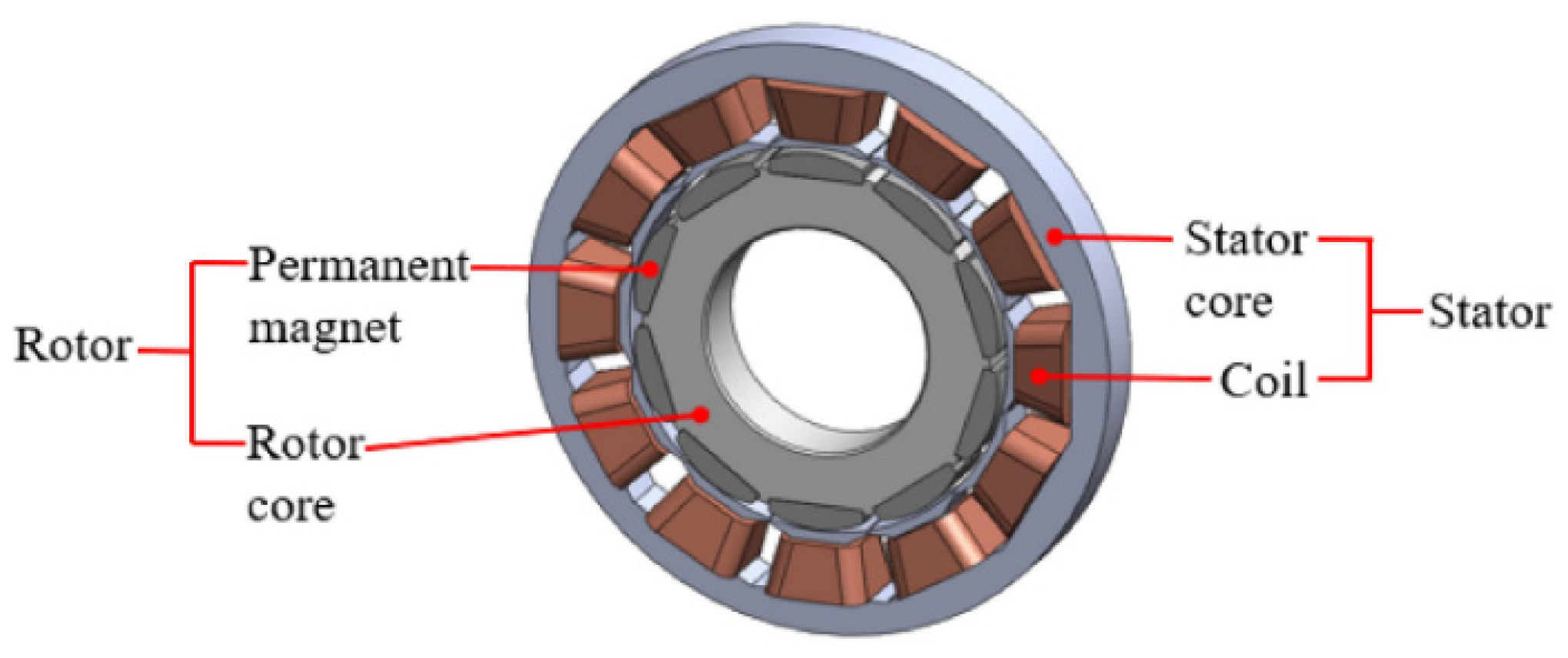
In this study, permanent magnet synchronous motors (PMSMs), one of the types of synchronous motors that have become rapidly popular in recent years due to their advantages, were examined (see Figure 1).
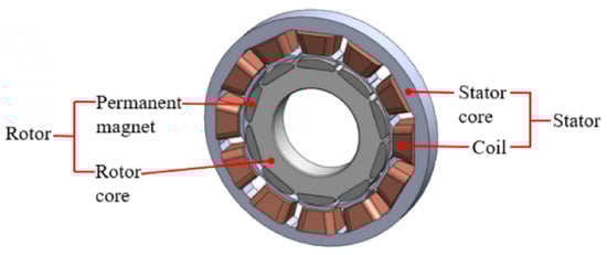
Figure 1.
Example of a permanent magnet synchronous motor [1].
With the rapid development of technology, there is a growing demand for higher quality and precision in applications that use electric motors, just as in other fields. The expectations for electric motors include improved torque quality and higher power density. This is also true for permanent magnet synchronous motors (PMSMs).
PMSMs are a type of motor that has become increasingly popular with the rise in the use of magnets, and they are frequently used in various applications. Especially since the rare-earth permanent magnet (PM) helps the motors have higher performance and downsizing, the PM is applied for the motors [2]. Compared to other motor types, they offer numerous advantages, including high power density, high efficiency, fast and dynamic response, a wide operating speed range, minimal maintenance requirements, and consequently a long lifespan. However, they also come with certain disadvantages.
A significant disadvantage of PMSMs is the high torque ripple, which has been extensively studied. In PMSMs, similar to synchronous motors, the use of magnets instead of windings in the rotor can lead to significant torque ripple. Many studies aim to identify the causes of torque ripple and seek to minimize these factors to reduce the overall torque ripple.
In the literature, studies can generally be categorized into two main areas: reducing torque ripple through motor design and control techniques. This study focuses on reducing torque ripple through motor design. The parameters that affect torque ripple in this research can generally be listed as follows:
- Motor mechanics and manufacturing;
- Cogging torque;
- Controller/electronics.
In [3], the importance of magnet shape in torque ripple is emphasized and examined. In some motors, if the magnet shape is not carefully designed, there can still be an increase in torque ripple even after offsetting the magnet/rotor. Research indicates that offsetting the rotor does not necessarily reduce torque ripple and may even cause it to increase.
In [4], it is noted that magnetic flux, the fundamental induced electromotive force (EMF) waveform, and motor geometry are important factors in determining the torque waveform. Studies have shown that torque ripple can be reduced from levels around 17% to as low as 7%. However, this reduction may also lead to a decrease in the average torque value.
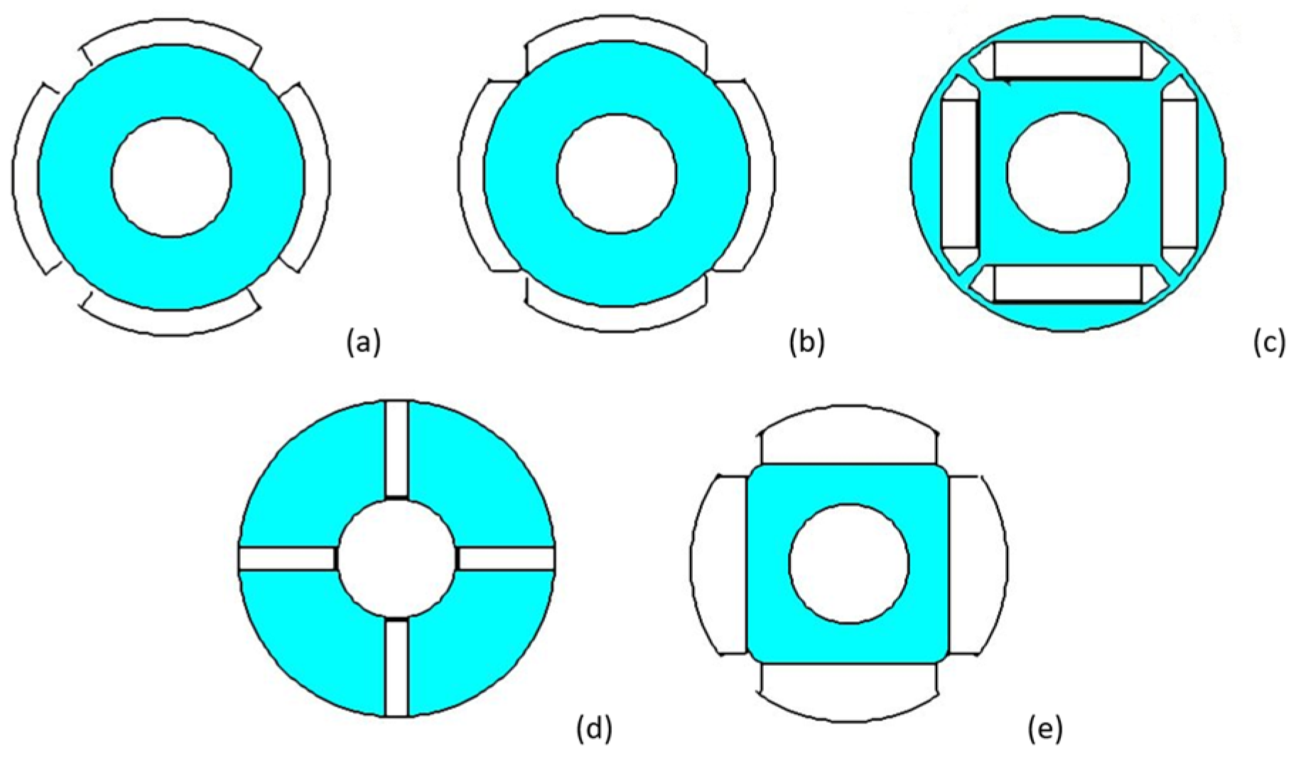
In [5], five commonly used rotor topologies are evaluated, considering permanent magnet materials and rotor cores of the same volume (see Figure 2). The bread-loaf rotor topology exhibits the highest torque, the least cogging torque, and the lowest torque ripple, providing better performance compared to other topologies.

Figure 2.
PMSM rotor topologies: (a) surface mounted–radially polarized; (b) surface mounted–parallelly polarized; (c) interior–parallelly polarized; (d) circumferential; (e) bread-loaf.
In [6], the effects of back EMF and cogging torque on torque ripple are examined using the finite element method. Generally, a reduction in cogging torque leads to a decrease in torque ripple. However, the relationship between cogging torque and torque ripple may not always follow this trend. This is because the methods applied to reduce cogging torque can also alter the shape of the back EMF, which does not guarantee a reduction in torque ripple.
In [7], the focus is on determining design parameters to reduce torque ripple in sinusoidally excited permanent magnet synchronous motors. In most cases, techniques for minimizing torque ripple are addressed on the drive side. However, in addition to the controller and drive electronics, the machine itself also contributes to torque ripple and non-linear torque characteristics. Typically, cogging torque and harmonic contents in the back EMF are minimized to reduce torque ripple. Furthermore, the analyses performed reveal that the magnet material does not provide a significant contribution to the differences in torque ripple.
In [8], new methods are proposed to improve the torque quality of a surface-mounted (SM) PMSM in a servo system. These methods ensure that torque ripple is reduced without significantly decreasing the average torque. Minimizing cogging torque or optimizing the back EMF are effective methods to address the torque ripple issue. In many studies and in the literature, when focusing on reducing torque ripple, another common problem encountered in PM machines is the reduction in average torque. Therefore, finding a method that can reduce torque ripple without causing a loss in average torque is both a remarkable and challenging research topic, inspiring new studies.
Numerous studies and literature indicate that when focusing on reducing torque ripple, a common issue faced by PM machines is the decrease in average torque. Finding a method to reduce torque ripple without a drop in torque value is a notable and challenging task.
Since control techniques have been more extensively reviewed in the literature, the aim of [9] is to provide information on different design methods for reducing torque ripple in various topologies of permanent magnet motors. To this end, the design methods are categorized into three groups: geometry optimization, slot–pole combinations, and stator winding shapes. It appears that geometry optimization is the broadest category, followed by stator winding shapes and slot–pole combinations.
Therefore, as performed in most literature studies, this work also addresses different design methods for a single type of motor.
In this study, solutions are sought for the torque ripple of PMSMs through various designs and analyses using the finite element method (FEM). Simulating design variations using the FEM can improve PMSM design, and by optimizing the parameters based on the FEM, even better results can be achieved [10]. The changes in torque ripple have been examined and evaluated. It has been observed that the analytical solutions are consistent with the information found in the literature. The stages of this study and evaluations are detailed in the following sections.
2. Servo Motor and Specifications
The motor under examination is a type of permanent magnet synchronous motor known as a servo motor. A servo motor enables precise control of position, speed, and torque.
Servo motors demonstrate highly accurate performance over a wide range of torque and speed, thanks to other components in the system, such as sensors, drivers, and closed-loop control. They are preferred for their ability to provide extensive speed control, minimal maintenance requirements, and low failure rates. Due to these characteristics, servo motors are commonly used in applications such as robotics and automation, CNC, automated mass production, healthcare, and defense systems, where smooth and precise movement is desired.
For the design and control of a permanent magnet synchronous motor or servo motor, a mathematical model must be established. The mathematical model of the motor can be defined using space vectors. In this context, the general torque equation for PMSMs is given in (1).
This torque expression consists of two components: the magnetic torque and the reluctance torque. When these components are separated, they can be expressed as the magnetic torque (2) and the reluctance torque (3).
In the torque expressions, p represents the number of pole pairs, ψm denotes the magnetic flux, and id,q are the currents in the d and q axes, respectively, while Ld,q indicate the inductance values in the d and q axes.
In surface-mounted permanent magnet (SPM) motors, the d and q axis inductances are approximately equal. As a result, reluctance torque does not occur in SPM motors. Therefore, the general torque expression for SPM motors is as shown in (2).
As can be seen, the torque equation does not include variations such as inductance and flux that occur due to motion in surface-mounted (SPM) servo motors. Consequently, the fluctuations in torque cannot be mathematically expressed. Thus, the components that influence the torque ripple of PMSMs must be thoroughly analyzed.
This study focuses on the torque fluctuations resulting from motor mechanics and cogging torque. As can be seen from the torque expression in (2), it can be stated that the magnetic flux directly affects the torque ripple of SPM servo motors. Accordingly, the torque ripple is investigated by modifying the magnet geometry of a reference servo motor.
Various computer-aided software tools are used for the design, modeling, and analysis of electric motors. The most commonly used tool among these is the ANSYS 2023 software. The design, modeling, and analyses were conducted using the “RMxprt” and “Maxwell 2D” modules of the ANSYS software suite, like as [11].
The fundamental characteristics of the reference servo motor are presented in Table 1.

Table 1.
Reference servo motor.
The servo motor model obtained from the design is shown in Figure 3. Some important performance characteristics resulting from the modeling of the servo motor are presented in Table 2. This reference design is adopted from a commercial servo motor.
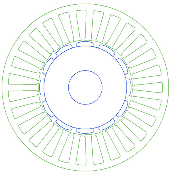
Figure 3.
The designed reference servo motor model.
Table 2.
Some performance characteristics of the designed reference servo motor.
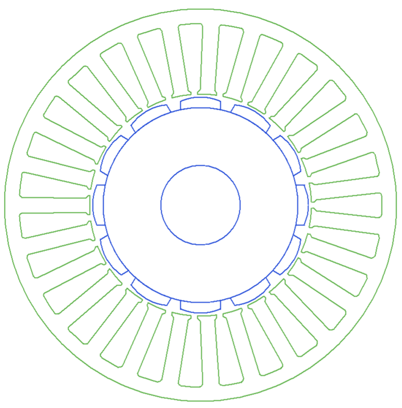
The design results were transferred to the “Maxwell 2D” analysis module for detailed analysis. As can be seen from Table 1, the control type is AC. No changes have been made to this transfer. So, the motor drive technique has been adjusted to voltage-fed. As seen in Figure 4, a symmetric component of the motor geometry was considered in “Maxwell 2D” to reduce the analysis time.
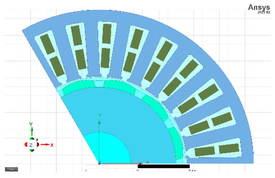
Figure 4.
Cross-section of the reference servo motor in Maxwell 2D.
The analysis results were examined in terms of torque, phase-to-phase induced voltage, magnetic flux density, and cogging torque. The results obtained in this context are presented in Figure 5, Figure 6, Figure 7 and Figure 8.

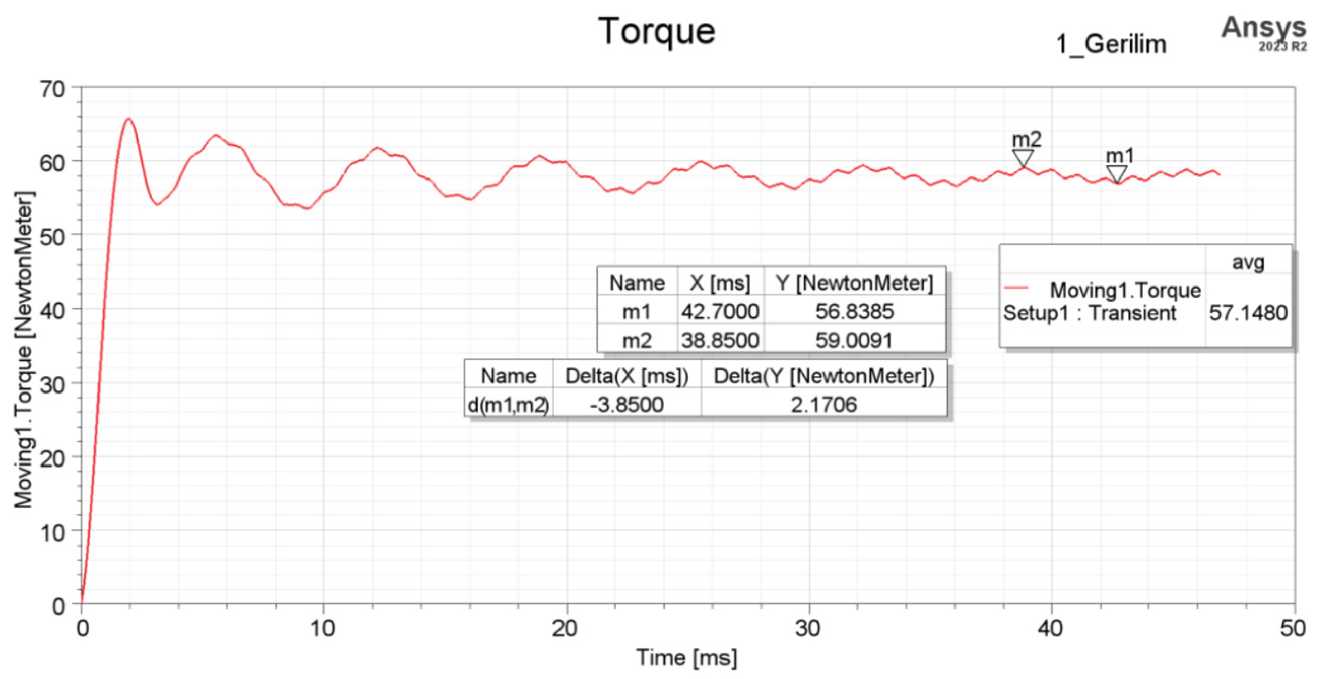
Figure 5.
Torque characteristics of the reference servo motor.
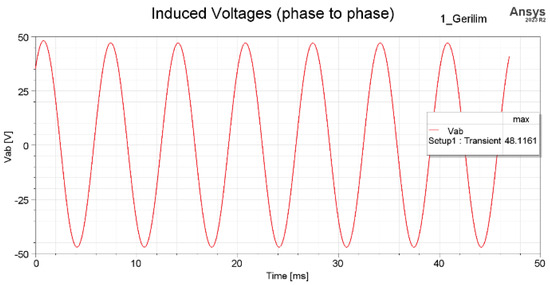
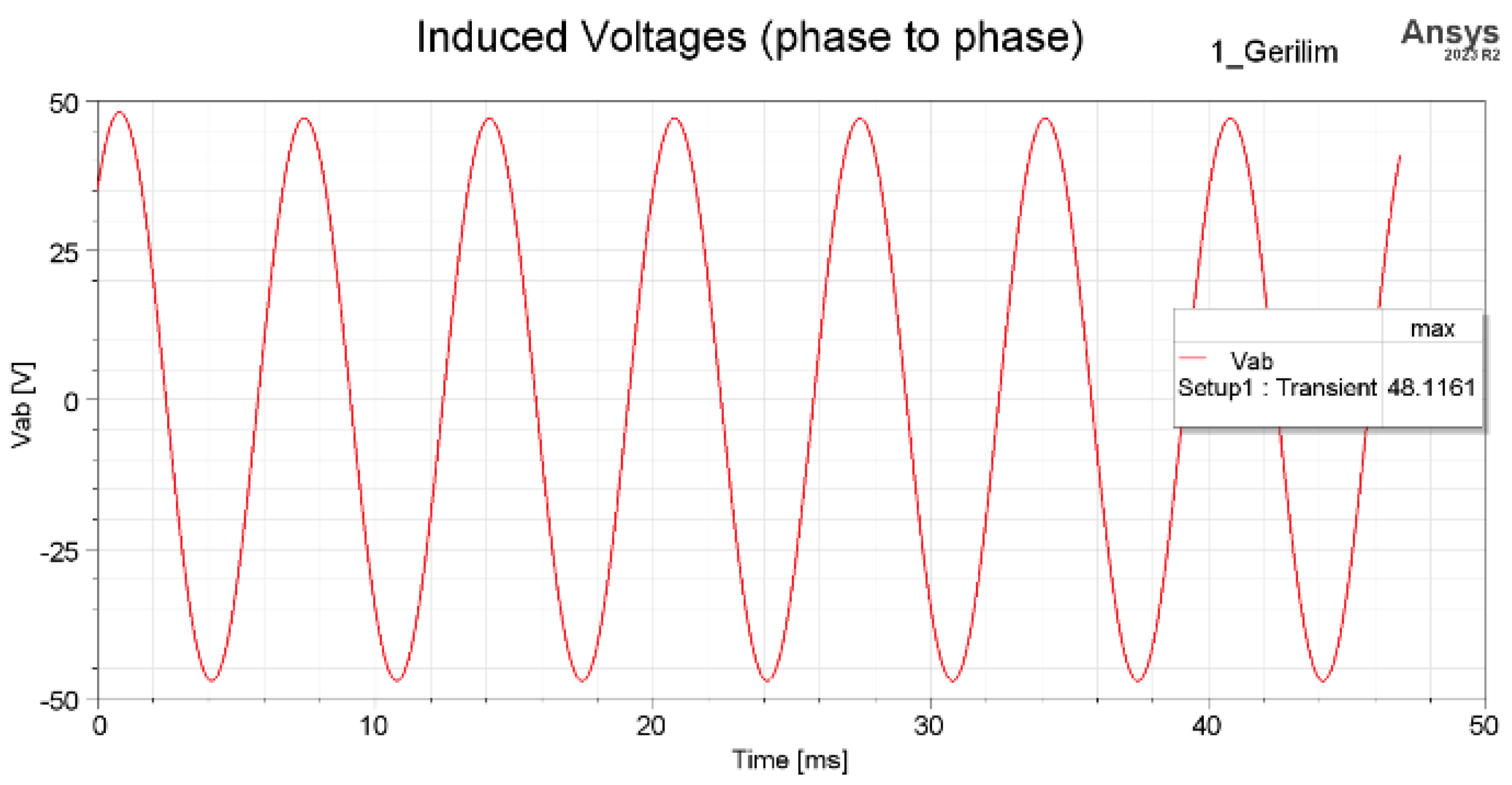
Figure 6.
Induced voltage characteristics of the reference servo motor.
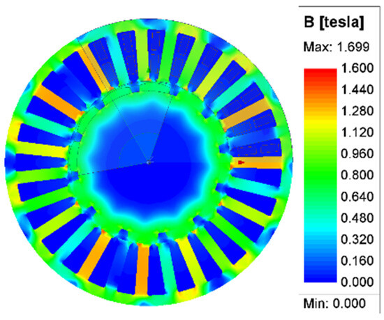
Figure 7.
Magnetic flux density of the reference servo motor.
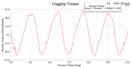
Figure 8.
Cogging torque characteristics of the reference servo motor.
In Figure 5, the torque has stabilized over time, and as a result, the expected torque value from the motor has been closely achieved. This figure shows the time on the x-axis in milliseconds [ms] and the torque values on the y-axis in NewtonMeter [Nm]. The variation in torque over time and torque ripple can be observed in this graph. Here, the reference motor exhibits a torque ripple of 2.17 Nm and a torque amplitude of 57.92 Nm.
In Figure 6, the induced voltage between phases has been analyzed in Maxwell 2D as expected, yielding 48 VDC.
In Figure 7, the distribution of magnetic flux density is shown, and it can be observed that the magnetic material is not in the saturation region.
In Figure 8, the waveform and amplitude of the cogging torque are provided as a result of the Maxwell 2D analysis. Here, the x-axis represents the rotor position in degrees [deg], while the y-axis shows the cogging torque in milli-NewtonMeter [mNm]. The cogging torque has an amplitude of 67.8 mNm, and its position-dependent variation averages nearly zero (0) mNm, as expected.
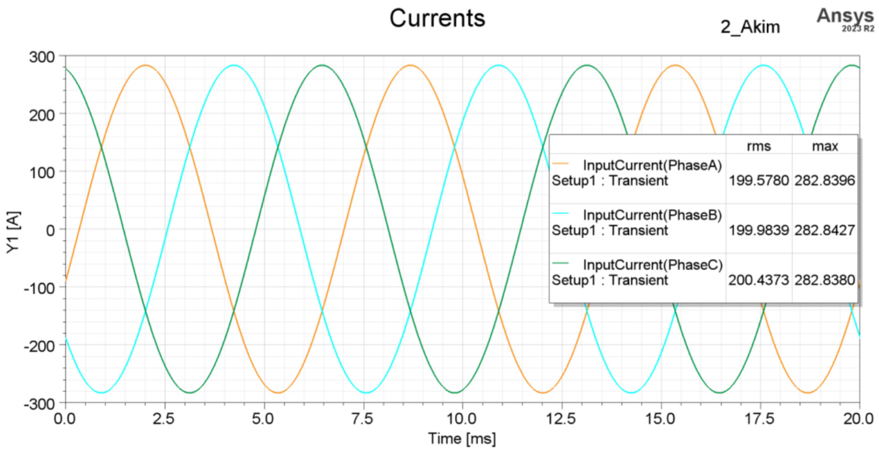
The reference motor current waveform is given in Figure 9. It can be seen that the current waveform is in a balanced and smooth sinusoidal form, and the windings are also in this form.
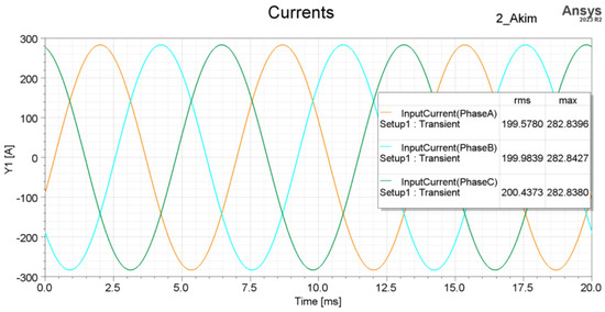
Figure 9.
Current waveform characteristics of the reference servo motor.
3. Comparison of Alternative Servo Motors
To investigate and improve the torque ripple of the reference servo motor, alternative designs were developed through design and analysis activities. These designs were achieved by altering the magnet geometry. Changes were made to the geometry using the parameters of magnet offset and magnet width (see Figure 10).
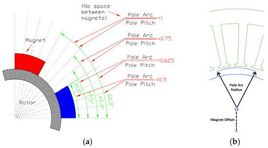
Figure 10.
Magnet demonstration: (a) magnet embrace [12] and (b) magnet offset.
With the change in magnet offset, a bulge or dome is formed in the magnet. This bulge alters both the magnet and the air gap, leading to changes in torque and associated components. Four different values for magnet offset were determined based on physical limits and optimization studies.
Changing the magnet width (or magnet embrace) affects the amount of magnets present on the rotor surface. This results in performance variations and changes in torque and associated components. Three different values for magnet width were similarly determined based on physical limits and optimization studies.
During this process, the stator geometry and winding structure were not altered in any way. Analysis studies for the alternative designs were carried out similar to those of the reference servo motor. In other words, all analyses were performed using Maxwell 2D, and the results obtained were compared with those of the reference servo motor. The comparison criteria included torque ripple, cogging torque, and cost impact.
The comparisons related to torque ripple are presented in Table 3 and Table 4. As seen, at high values of magnet offset compared to the reference servo motor, the torque ripple decreases and improves. The torque ripple drops from 2.17 Nm to 1.71 Nm with an increase of 4 mm in the magnet offset. This radical change is more clearly observed in the torque ripple, which decreases to 1.23 Nm with an increase of 9 mm in the magnet offset. However, this situation is disadvantageous in terms of the torque coefficient, leading to a loss in performance.
Table 3.
Comparison of torque ripple for magnet offset.
Table 4.
Comparison of torque ripple for magnet embrace.
On the other hand, in the case of changing the magnet width (or magnet embrace), there is very little change in torque ripple compared to the reference servo motor. This is because altering the magnet width significantly affects the servo motor’s performance. The torque ripple, initially at 2.17 Nm, was reduced to 1.73 Nm.
The comparisons of cogging torque are presented in Table 5 and Table 6. According to the analysis results, as the magnet offset values increase, the amplitude of the cogging torque decreases. This situation positively contributes to torque variation. Similar results have also been observed in the comparison of torque ripple. On the other hand, it has been noted that both an increase and a decrease in the magnet width compared to the reference servo motor result in a reduction in the amplitude of the cogging torque (except for the value of 0.56). This similarly provides a positive contribution to torque variation.
Table 5.
Comparison of cogging torque for magnet offset.
Table 6.
Comparison of cogging torque ripple for magnet embrace.
In both methods, the amplitude of the cogging torque decreases from approximately 67.8 mNm to around 20–22 mNm. Additionally, it has been observed that the average values of the cogging torque exhibit oscillation around zero, alternating between (−) and (+), similar to the behavior seen in the reference servo motor with changes in magnet geometry.
The cost comparison has been made in terms of the quantities of magnets, as only changes in magnet geometries have occurred in the alternative servo motor designs compared to the reference servo motor. There have been no modifications to the stator, windings, or rotor. The comparisons are presented in Table 7 and Table 8.
Table 7.
Magnet weight for different magnet offsets.
Table 8.
Magnet weight for different magnet embraces.
The change in magnet weight due to variations in magnet offset is minimal (2.22 kg–1.76 kg). On the other hand, the magnet offset process requires significant cost and time in terms of magnet production. Considering this, the reduction in magnet costs is balanced by the processing costs. Therefore, all designs can have similar overall costs.
For variations in magnet width, the change in magnet weight is slightly more significant (1.58 kg–2.32 kg). In this case, there will be no additional processing or costs for magnet production. Thus, changes in magnet weight due to magnet width variations can be directly considered as changes in cost.
For high-volume productions, magnet costs fall within the scope of the above evaluation for both methods compared to conventional magnet geometries.
Given all these results, a selection must be made based on the application of the servo motor for torque ripple and other performance criteria. This is important because improvements in torque ripple may lead to disadvantages in other performance and cost criteria.
4. Conclusions
The servo motor is a type of permanent magnet synchronous motor that enables precise control of position, speed, and torque. Due to these features, servo motors are widely used in applications such as robotics and automation, CNC, automated mass production, healthcare, and defense systems, where smooth and accurate movement is required.
The aim of this study is to investigate and evaluate torque ripple through changes in magnet geometry to enhance torque quality.
A reference servo motor was designed, and its analysis was conducted using the finite element method (FEM). Alternative servo motor designs were created by modifying magnet geometry, and similar FEM analyses were performed. The analysis results were shared in detail, evaluating torque ripple, cogging torque, and cost effects.
This study shows that torque ripple could be improved from 2.17 Nm to 1.23 Nm, and cogging torque could be reduced from 67.8 mNm to 22 mNm.
However, performance losses can occur in proportion to the improvement in torque ripple. Therefore, it is recommended to design and select the servo motor based on the specific application.
Moreover, studies and analyses have been conducted for the nominal speed value, which presents significant challenges in terms of torque. This is because the reference servo motor is consistently operated at its nominal speed. Therefore, for future academic studies, a similar analysis or study could be recommended for the low-speed range and speeds below the nominal value. This would enable a comprehensive assessment of torque ripple and cogging torque variations across all operational regions of the servo motor.
Author Contributions
Conceptualization, H.D.; methodology, H.D.; validation, H.D.; investigation, H.D.; resources, H.D.; data curation, H.D.; writing—original draft, H.D.; writing—review and editing, E.A. and M.G.A.; visualization, H.D.; supervision, E.A. and M.G.A.; project administration, H.D. All authors have read and agreed to the published version of the manuscript.
Funding
This research received no external funding.
Data Availability Statement
The original contributions presented in this study are included in the article. Further inquiries can be directed to the corresponding author.
Acknowledgments
We would like to express our gratitude to ASELSAN for their support for this study.
Conflicts of Interest
Author Hacı Dedecan was employed by the company ASELSAN. The remaining authors declare that this research was conducted in the absence of any commercial or financial relationships that could be construed as a potential conflict of interest.
References
- Choe, J.; Kwon, H.; Kim, H.; Koo, D.; So, H. Structural effects of asymmetric magnet shape on performance of surface permanent magnet synchronous motors. Sci. Rep. 2024, 14, 3976. [Google Scholar] [CrossRef] [PubMed]
- Jeong, C.; Park, J.; Bianchi, N. Alternatives to replace rare-earth permanent magnet motors in direct drive applications. In Proceedings of the 2020 International Symposium on Power Electronics, Electrical Drives, Automation and Motion (SPEEDAM), Sorrento, Italy, 24–26 June 2020; pp. 276–281. [Google Scholar]
- Islam, R.; Husain, I.; Fardoun, A.; McLaughlin, K. Permanent magnet synchronous motor magnet designs with skewing for torque ripple and cogging torque reduction. In Proceedings of the 2007 IEEE Industry Applications Annual Meeting, New Orleans, LA, USA, 23–27 September 2007; pp. 1552–1559. [Google Scholar]
- Chaieb, M.; Tounsi, S.; Neji, R.; Sellami, F. Optimum geometry for torque ripple minimization of permanent magnet motor by the finite element method. In Proceedings of the MELECON 2008-The 14th IEEE Mediterranean Electrotechnical Conference, Ajaccio, France, 5–7 May 2008; pp. 459–464. [Google Scholar]
- Vakil, G.I.; Rajagopal, K.R. Performance comparison of sinusoidally-fed PM BLDC motors having different rotor topologies. In Proceedings of the 2010 Joint International Conference on Power Electronics, Drives and Energy Systems & 2010 Power India, New Delhi, India, 20–23 December 2010; pp. 1–5. [Google Scholar]
- Kim, T.W.; Chang, J.H. Influence of cogging torque reduction method on torque ripple in a surface-mounted permanent magnet synchronous motor. J. Magn. 2012, 17, 109–114. [Google Scholar] [CrossRef]
- Islam, M.S.; Islam, R.; Sebastian, T. Experimental verification of design techniques of permanent-magnet synchronous motors for low-torque-ripple applications. IEEE Trans. Ind. Appl. 2010, 47, 88–95. [Google Scholar] [CrossRef]
- Zeng, Y.; Cheng, M.; Liu, G.; Zhao, W. Effects of magnet shape on torque capability of surface-mounted permanent magnet machine for servo applications. IEEE Trans. Ind. Electron. 2019, 67, 2977–2990. [Google Scholar] [CrossRef]
- Suriano-Sánchez, S.I.; Ponce-Silva, M.; Olivares-Peregrino, V.H.; De León-Aldaco, S.E. A review of torque ripple reduction design methods for radial flux PM motors. Eng 2022, 3, 646–661. [Google Scholar] [CrossRef]
- Frizzo Stefenon, S.; Seman, L.O.; Schutel Furtado Neto, C.; Nied, A.; Seganfredo, D.M.; Garcia da Luz, F.; Quietinho Leithardt, V.R. Electric field evaluation using the finite element method and proxy models for the design of stator slots in a permanent magnet synchronous motor. Electronics 2020, 9, 1975. [Google Scholar] [CrossRef]
- Abd-Al Kareem, E.; Ali, A.M. Finite element analysis of cogging torque and torque ripple of brushless DC motor. Wasit J. Eng. Sci. 2024, 12, 135–151. [Google Scholar] [CrossRef]
- Ocak, C.; Tarimer, I.; Dalcali, A.; Uygun, D. Investigation effects of narrowing rotor pole embrace to efficiency and cogging torque at PM BLDC motor. TEM J. 2016, 5, 25. [Google Scholar] [CrossRef]


Disclaimer/Publisher’s Note: The statements, opinions and data contained in all publications are solely those of the individual author(s) and contributor(s) and not of MDPI and/or the editor(s). MDPI and/or the editor(s) disclaim responsibility for any injury to people or property resulting from any ideas, methods, instructions or products referred to in the content. |
© 2025 by the authors. Licensee MDPI, Basel, Switzerland. This article is an open access article distributed under the terms and conditions of the Creative Commons Attribution (CC BY) license (https://creativecommons.org/licenses/by/4.0/).