Article

Advanced Magnetic Coupling Resonance Model Optimization for Enhanced Wireless Power Transfer

State Key Laboratory of Electronic Testing Technology, North University of China, Taiyuan 030051, China
*
Author to whom correspondence should be addressed.
Electronics 2025, 14(6), 1152; https://doi.org/10.3390/electronics14061152
Submission received: 17 February 2025 / Revised: 12 March 2025 / Accepted: 13 March 2025 / Published: 14 March 2025

Abstract

:
To address the demand for improved electrical performance parameters in the field of magnetically coupled resonant wireless power transfer (MCR-WPT), this paper conducts an in-depth theoretical simulation and validation of key processes, including electrical signal isolation, inversion, phase detection, and rectification filtering. This study proposes and verifies the impact of transmitter and receiver coil structural parameters on transmission performance, leading to an optimized design. Additionally, a fully digital phase-locked loop (PLL) is implemented to achieve the full-band frequency locking and tracking of wireless power oscillation transmission, ensuring continuous resonance during power transfer for maximum efficiency. Through theoretical simulations and experimental validation, results confirm that under optimized coil structures and frequency-locking technology, transmission efficiency can be improved by up to 13% compared to conventional methods, with an increase of 8 W in transmitted power. The optimized system has demonstrated long-term operational stability and reliability, providing valuable insights for advancing applications in the field.

1. Introduction

With the continuous advancement of power electronics technology, wireless charging has emerged as one of the most promising future developments to meet user demands for convenience, efficiency, and environmental sustainability. A key challenge in this technology lies in improving transmission efficiency and ensuring safe and reliable operation in various application scenarios. Wireless power transfer (WPT) encompasses several implementation methods, including electromagnetic induction, magnetically coupled resonance, and microwave-based wireless power transfer [1,2,3]. These methods utilize space media such as magnetic fields, electric fields, lasers, and microwaves as carriers to transfer electrical energy from the source to the load in a non-contact manner. As shown in Table 1, the main wireless transmission technologies are compared in terms of key performance indicators. Among them, microwave radiation-based transmission enables long-distance power transfer but poses potential electromagnetic radiation hazards to users, while electromagnetic induction-based transmission is limited in range.
Magnetic Coupling Resonance Wireless Power Transfer (MCR-WPT) utilizes the principle of electromagnetic induction to transmit electrical signals through frequency resonance. The block diagram of its working principle is shown in Figure 1. This system achieves high-efficiency energy transfer by inverting the power supply and generating resonance in the wireless transmission and reception modules. Due to its advantages, including low-radiation intensity, wireless transmission distances on the order of meters, an operational frequency range covering several tens of kilohertz to hundreds of megahertz, transmission efficiency of no less than 80%, and strong anti-interference capability, MCR-WPT has increasingly demonstrated its applicability in everyday applications.
Considering factors such as transmission distance and environmental sustainability, this study focuses on optimizing the Magnetic Coupling Resonance Wireless Power Transfer (MCR-WPT) method. Currently, MCR-WPT is one of the fastest-growing technologies in this field. According to the resonance effect mechanism, the system achieves maximum transmission efficiency when the transmitting and receiving modules establish effective resonance. However, factors such as position deviation and distance variation can lead to detuning between the transmitter and receiver, reducing energy conversion efficiency.
Most research efforts have, therefore, focused on stabilizing the resonance frequency tuning process. These approaches can be broadly categorized into two main methods: adjusting compensation circuits within the system or modifying the excitation power signal’s oscillation frequency based on power output frequency variations.
Reference [4] explores frequency synchronization in wireless transmission using a matrix compensation capacitor method. However, due to individual component differences, capacitor value inconsistencies prevent achieving optimal tuning performance. References [5,6,7] employ transistors in conjunction with compensation capacitors in resonance circuits to stabilize the resonance frequency. However, the impact of resonance topology on system transmission power and resonance frequency varies, leading to additional system design challenges. A commonly used approach is modifying the system’s power output frequency to continuously match the resonance frequency. This method offers advantages such as high stability, precision, and simplicity. Reference [8] implements an analog phase-locked loop (PLL) with a fixed central frequency for oscillation frequency tracking. However, its applicability is limited in wideband frequency applications, and it fails to track frequency changes when the system exhibits wide-range multi-frequency oscillations. Reference [9] introduces a software-based frequency adjustment and tracking method, but it lacks automatic adaptive frequency tuning, resulting in a reduced tuning speed and system stability. In contrast, Reference [10] proposes a high-precision PLL design concept, establishing a mathematical model for the high-precision PLL and analyzing a selection of relevant parameters. However, it provides limited details on specific design implementations.
This study optimizes the transmission performance of wireless charging technology, from power to efficiency, through theoretical simulations and practical applications. The final results indicate that by appropriately selecting winding parameters and implementing frequency tracking and phase-locking measures, an optimal design can be achieved, ensuring a wireless transmission efficiency of over 90% within a 10 cm distance and a transmission power of no less than 40 W.

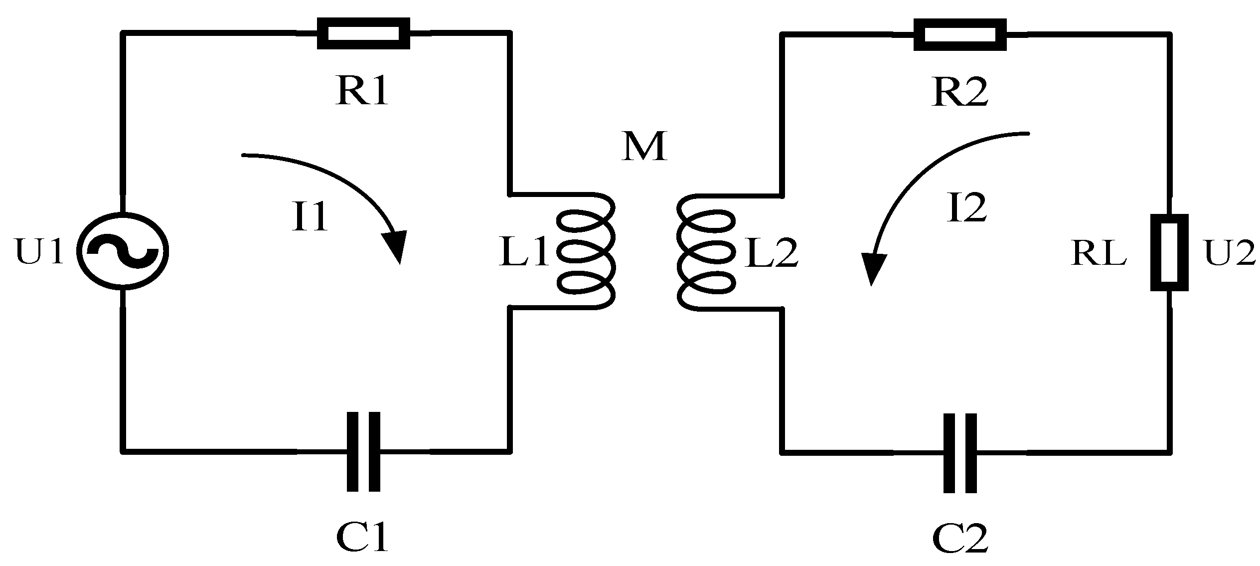
2. Circuit Modeling Analysis of MCR-WPT Coupled System

The principal model of Magnetic Coupling Resonance can be categorized into three analytical approaches. The first is the coupled-mode theory model, which analyzes the system’s energy conversion process by examining energy coupling and flow parameters [11]. The second is the two-port network model, which focuses solely on analyzing the energy transfer characteristics between the transmitter and receiver to evaluate the performance of the resonant coupling system. The third is the classical circuit theory analysis method, which applies circuit design principles and mutual inductance theory in a more detailed manner. This method allows for a deeper and more precise optimization of system performance. Therefore, this paper adopts the circuit theory analysis method for theoretical modeling of the Magnetic Coupling Resonance system [12].

2.1. Modeling Analysis of Magnetically Coupled Resonators

MCR-WPT (Magnetic Coupling Resonance Wireless Power Transfer) operates in the near-field region, utilizing coupling mechanisms for energy transfer. At the fundamental level, the system consists of several key components: a high-frequency inverter power module, a resonance compensation module, a wireless coupling circuit module, and a rectification and voltage regulation module. Energy from the inverter power module is coupled through a magnetic field at the same frequency into the receiving circuit, where it is rectified and regulated into a suitable power supply for the load. Various circuit coupling structures and resonance tuning circuits within the system significantly influence parameters such as transmitted power, efficiency, and transmission distance.
MCR-WPT commonly employs two-coil and multi-coil coupling structures to achieve wireless power transfer. These systems rely on coil assemblies and discrete components like capacitors and inductors to establish resonance, thereby maximizing energy transfer efficiency. The most frequently used resonance compensation topologies can be classified into four types based on the connections of capacitors and inductors: series–series (S-S), series–parallel (S-P), parallel–series (P-S), and parallel–parallel (P-P) connections. By applying Kirchhoff’s laws and circuit analysis theories, the modeling and analysis of these four compensation circuits reveal the impact of different circuit structures on power output and transmission efficiency. As illustrated in Figure 2, the series–series (S-S) topology exhibits specific power output and transmission efficiency characteristics during wireless energy transfer.
Output power:
P = U 1 2 ω 2 M 2 R L R 1 R 2 + R L + ω 2 M 2 2
Transmission efficiency:
η = U 2 I 2 U 1 I 1 = ω 2 M 2 R L R 2 + R L R 1 R 2 + R L + ω 2 M 2
In this model, C1 and C2 represent the compensation capacitors at the transmitting and receiving ends, respectively, while R1 and R2 denote the internal resistances of the transmitting and receiving circuits. RL represents the load resistance that consumes the transmitted power, and M is the mutual inductance parameter between the coils. In the series–series (S-S) compensation topology, the energy transfer efficiency is highly dependent on the coil’s internal resistance. In contrast, the other three compensation structures (S-P, P-S, and P-P) are influenced not only by internal resistance but also by the interaction between the compensation inductors and capacitors within the circuit.
The three-coil coupling structure, as shown in Figure 3, introduces an additional relay coil. While this configuration extends the transmission distance to some extent, it also increases system power loss and reduces transmission efficiency. Therefore, for high-frequency, long-distance wireless power transfer applications, a multi-coil structure is often a more suitable choice.
In summary, to facilitate the verification of the effectiveness of the proposed improvements and to simplify parameter classification, this study primarily adopts the series–series (S-S) dual-coil model for validation.

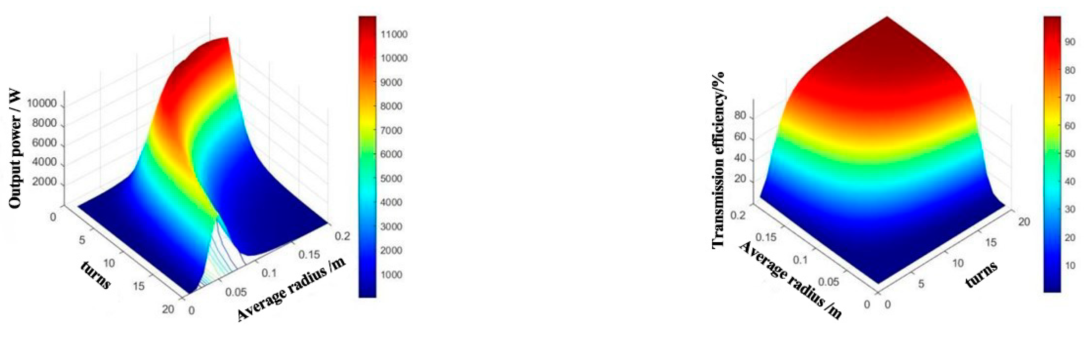
2.2. Optimized Design of MCR-WPT Transmission Performance and Coil Parameters

In the process of magnetic coupling wireless power transfer, the performance parameters can vary significantly due to the influence of the circuit structure. Therefore, the optimization design of the system primarily focuses on the study of the circuit structure and electrical parameters. During transmission, the design parameters of the coils are a key challenge, as they directly affect the coupling efficiency and transmission power.
In the research field, planar spiral coil structures are commonly used for short-range power coupling due to their simple and flexible design, making them easy to integrate. The coils are typically divided into circular planar and rectangular planar winding methods. However, the rectangular planar structure, while facilitating integration, introduces the disadvantage of leakage magnetic fields that affect coupling performance. Therefore, this study uses the circular planar winding method to construct coupling coils.
In power coupling transmission, the mutual inductance effect between transmitting and receiving coils directly impacts transmission efficiency. Parameters such as the distance between coils, winding radius, and the number of turns all influence mutual inductance. In the case of two coaxially placed coils, the mutual inductance can be calculated as follows:
M = μ 0 π N 1 N 2 r 1 a ν g 2 r 2 a ν g 2 2 ( D 2 + r 1 a ν g 2 ) 1.5
where μ0 is the permeability parameter in vacuum, N1 and N2 are the number of turns of the receiving and transmitting coils, respectively, ϒ1avg and ϒ2avg are the average radius of the receiving and transmitting coils, respectively, and D is the distance between the two coils.
The coil winding structure is shown in Figure 4, where Dmax and Dmin represent the maximum outer diameter and minimum inner diameter of the wound coil, respectively; S is the spacing between the windings, N is the number of turns in the coil, W is the diameter of the winding wire, and Davg is the average radius of the coil.
In the simulation analysis of the coil structure parameters, since in practical engineering applications, multiple parameters change simultaneously, analyzing the change in multiple parameters is more meaningful. Based on the influence of the change in individual coil parameters on system performance, it is concluded that the number of turns in the coil and the average coil radius have the most significant impact on wireless power transfer performance. Therefore, this research focuses on the optimization design of these two parameters.
Figure 5 below shows the simulation results for the coupling coil with multiple parameters in an environment with an input voltage of 50 V, a working frequency of 200 kHz, a wire diameter of 1 mm, a transmission distance of 10 cm, and a 50 Ω load. The relationship between the coil’s average radius, the number of turns, and the electrical power conversion efficiency is expressed. From this figure, it can be observed that with the change in the average radius and number of turns, the output power increases and then decreases, while the output efficiency rises to a maximum point and then stabilizes. Therefore, when considering the optimal output power and transmission efficiency for the application, the comprehensive selection of these coil parameters should be taken into account simultaneously.

2.3. Optimization of Coil Parameter Selection

Based on the above simulation results and under the assumed working conditions, a Magnetic Coupling Resonance Wireless Power Transfer (MCR-WPT) system is designed with a wireless transmission distance of 10 cm, a circuit output power of 40 W, and transmission efficiency greater than 90%. The performance parameters resulting from different coil structural parameters are calculated according to the requirements, as shown in Table 2 and Table 3.

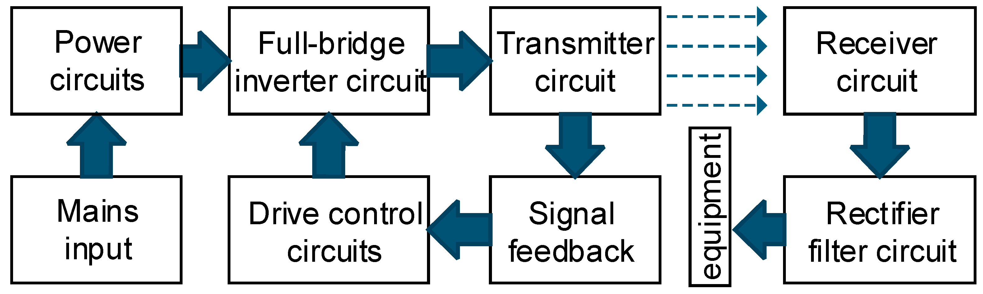
3. Analysis of Key Technologies for MCR-WPT System Design

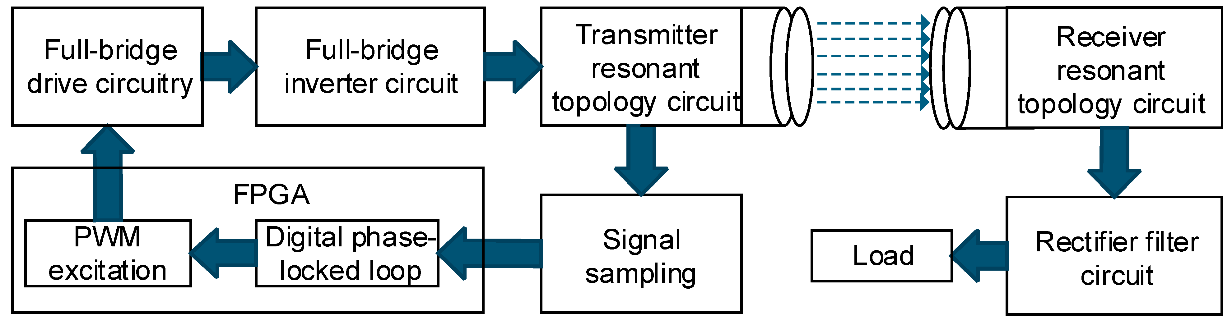
3.1. System Components

The MCR-WPT system designed in this paper primarily consists of an inverter circuit module, a coupling coil module, and a control circuit module, as illustrated in the system block diagram in Figure 6. While the application of the inverter and control circuits is already well established, increasing attention has been given to tuning the oscillation frequency between the transmitting and receiving coils. Maintaining resonance during power transfer ensures maximum coupling efficiency, leading to the development of various tuning methods. In traditional analog phase-locked loop (PLL) designs, coordination between the transmitter and receiver has been achieved to some extent. However, since the center frequency of such PLLs is fixed, their tuning bandwidth is limited. To address this issue, this paper proposes a fully digital PLL method that enables full-frequency dynamic tuning between the transmitter and receiver. If the system’s center frequency changes, the proposed method can adjust the output signal frequency of the inverter power supply to track the resonance frequency of the transmitting coil, achieving improved performance.

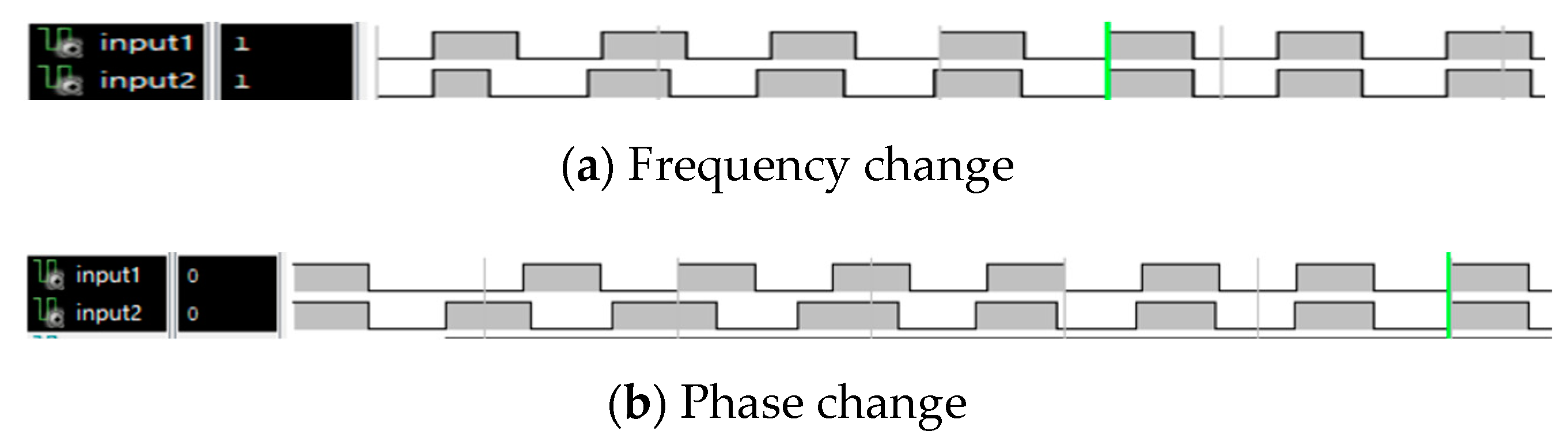
3.2. All-Digital Phase-Locked Loop Structure and Modeling Analysis

The digital phase-locked loop (DPLL) enables automatic adjustment between two different signals. It consists of three main components: a digital phase detector, a digital filter, and a numerically controlled oscillator (NCO). The phase detector determines the phase difference between the two signals, while the digital filter processes and counts the phase difference, driving the oscillator to achieve frequency locking [13,14]. The working principle is illustrated in the block diagram shown in Figure 7.
The hardware level logic simulation based on the design mechanism is shown in Figure 8.
As shown in the figure, when the signal frequency and phase deviate, the phase-locking system can effectively operate. Moreover, it achieves efficient frequency tracking adjustment within six signal cycles.

4. MCR-WPT System Simulation and Verification

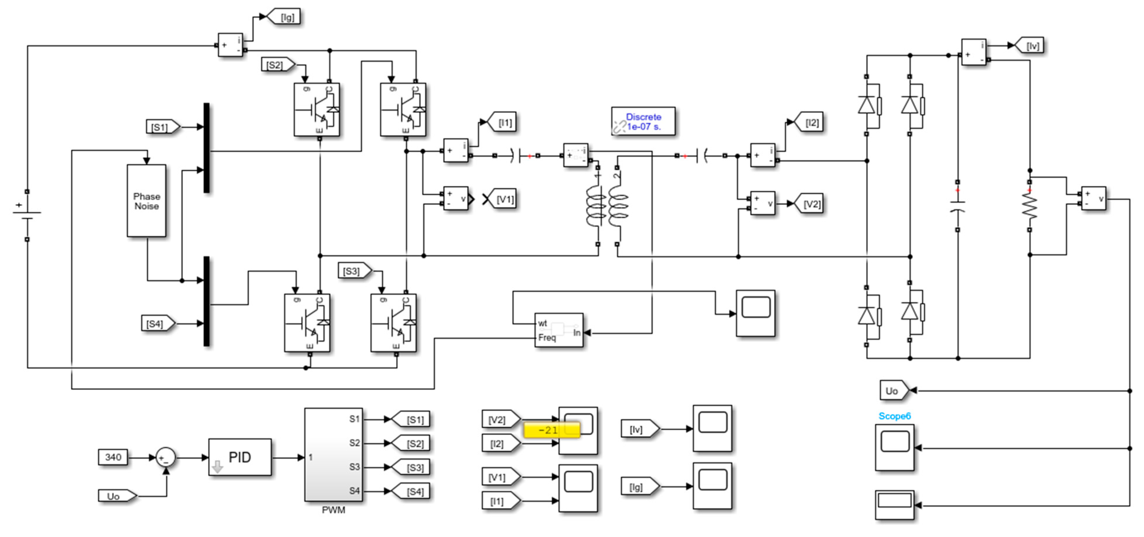
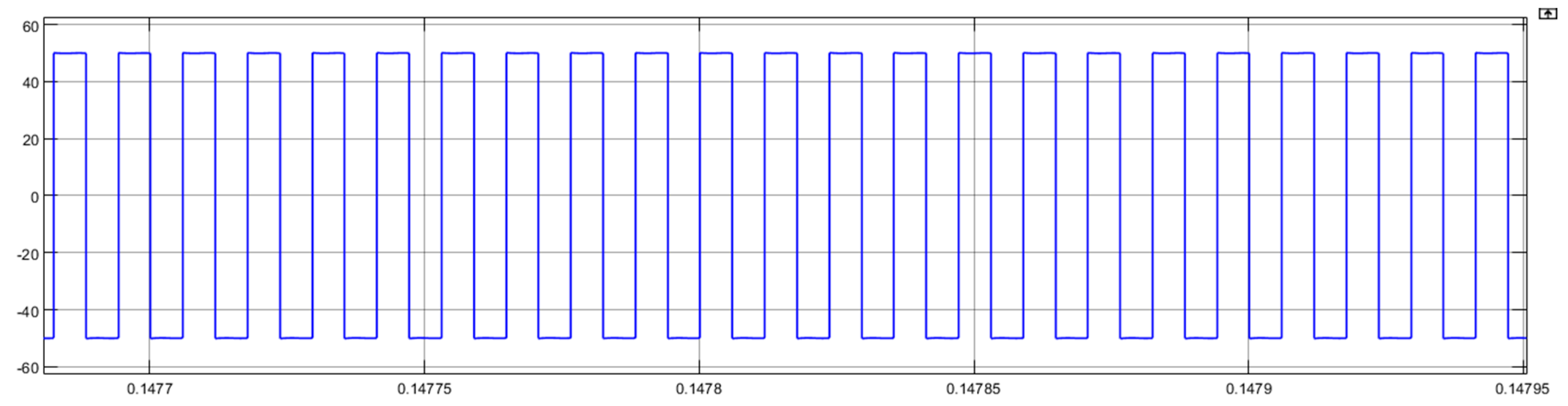
4.1. Simulation of Radio Energy Transmission System

After the system is built, the wireless transmission performance is first verified through a simulation. A circuit model is constructed using simulation software, as shown in Figure 9, Figure 10, Figure 11, Figure 12 and Figure 13. In the simulation, the input parameters are set to 20 V DC, with a system resonance frequency of 200 kHz and a load resistance of 50 Ω. By detecting the current phase, the PWM output frequency is adjusted dynamically to match the resonance frequency of the transmission system [15,16]. The simulation results are shown in Figure 9, Figure 10, Figure 11, Figure 12 and Figure 13.
Based on the simulation results, it can be observed that the designed circuit model effectively enables the inverter’s power supply to output efficiently at the theoretical level. By utilizing the frequency tracking method, the phase difference between the current and voltage is effectively minimized, ensuring that the MCR-WPT system operates under optimal resonance conditions. Ultimately, stable and efficient DC power is wirelessly transmitted to drive the load.

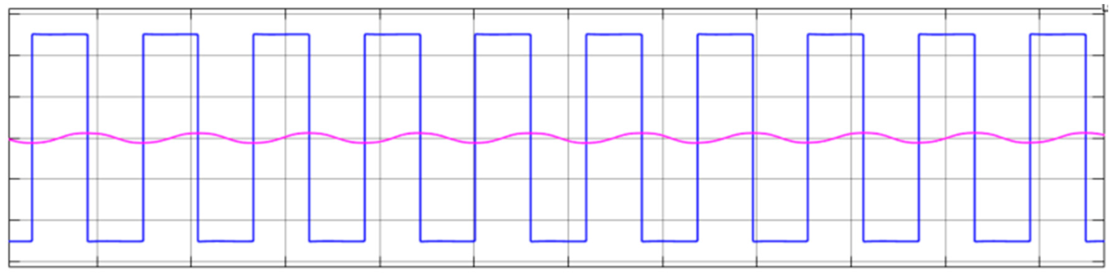
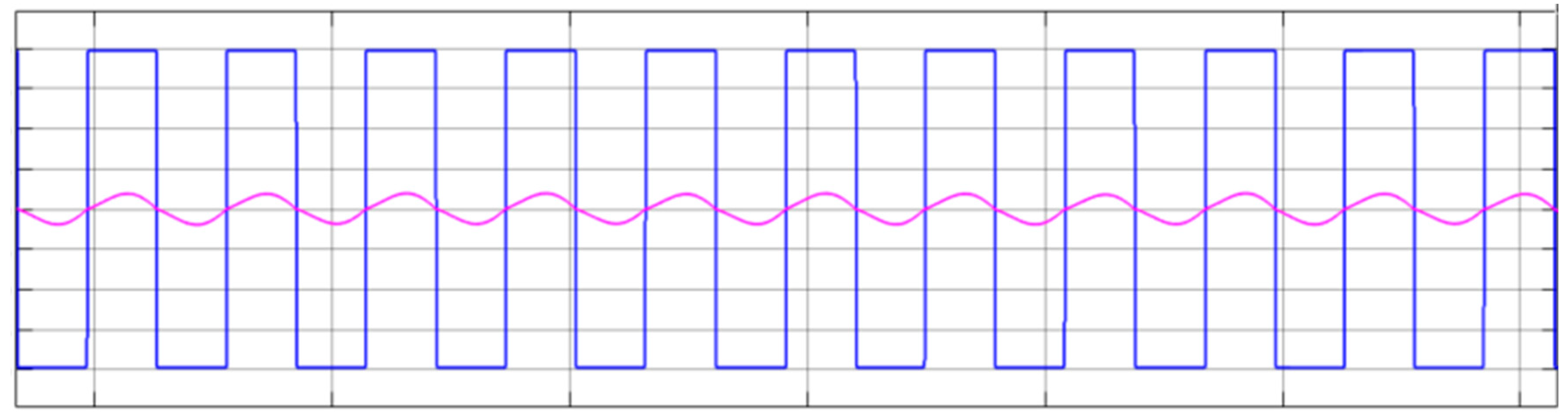
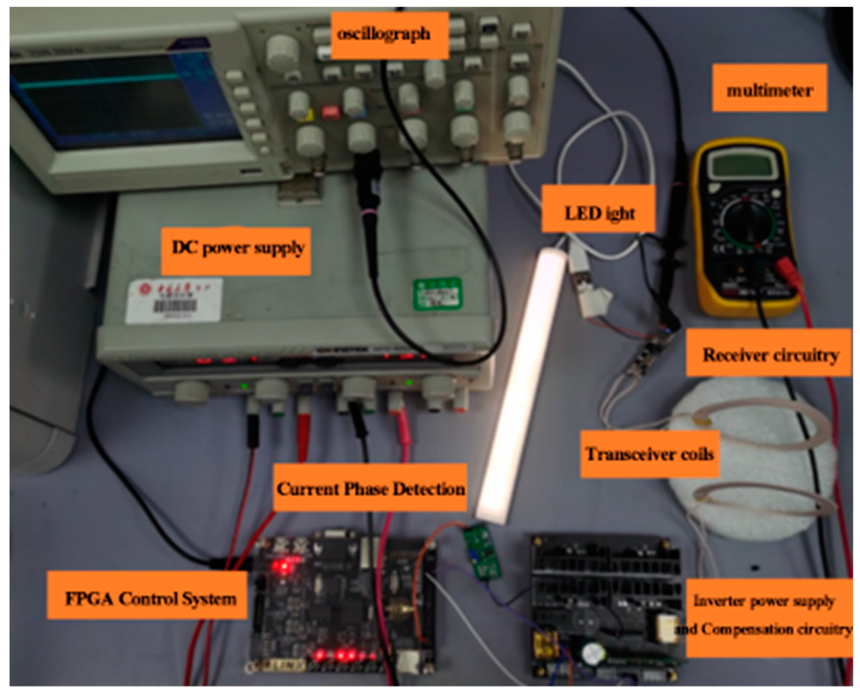
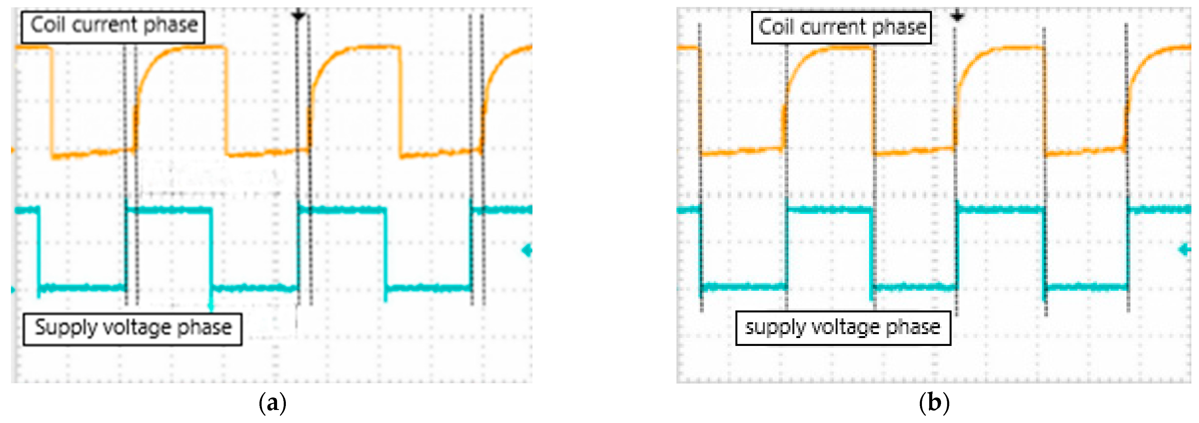
4.2. Experimental Platform Construction and Waveform Testing

According to the designed circuit principles and simulation results, an experimental platform was constructed, comprising a control circuit module, power inversion, and detection circuit module, coupling the coil set and resonance circuit, as well as a rectification and filtering circuit module. Through practical testing under a 20 V DC input voltage and an operating frequency of 200 kHz, wireless power transfer was successfully achieved over a distance of 10 cm, steadily illuminating a 3.5 W LED module. This verified the proper functioning of the proposed MCR-WPT system, as in Figure 14.
To verify the key design aspects of frequency tracking, an oscilloscope was used to measure the phase comparison before and after applying dynamic phase-locked technology. The voltage phase measurement point was taken from the inverter module’s output drive pulse signal, while the current phase was obtained from the feedback circuit module’s current-to-voltage conversion. The results are shown in Figure 15. According to the measurements, when a phase difference exists, the phase-locked frequency tracking effectively synchronizes the input and reference signals, achieving coordinated oscillation and enhancing the performance of the wireless power transfer system [17,18,19,20,21].

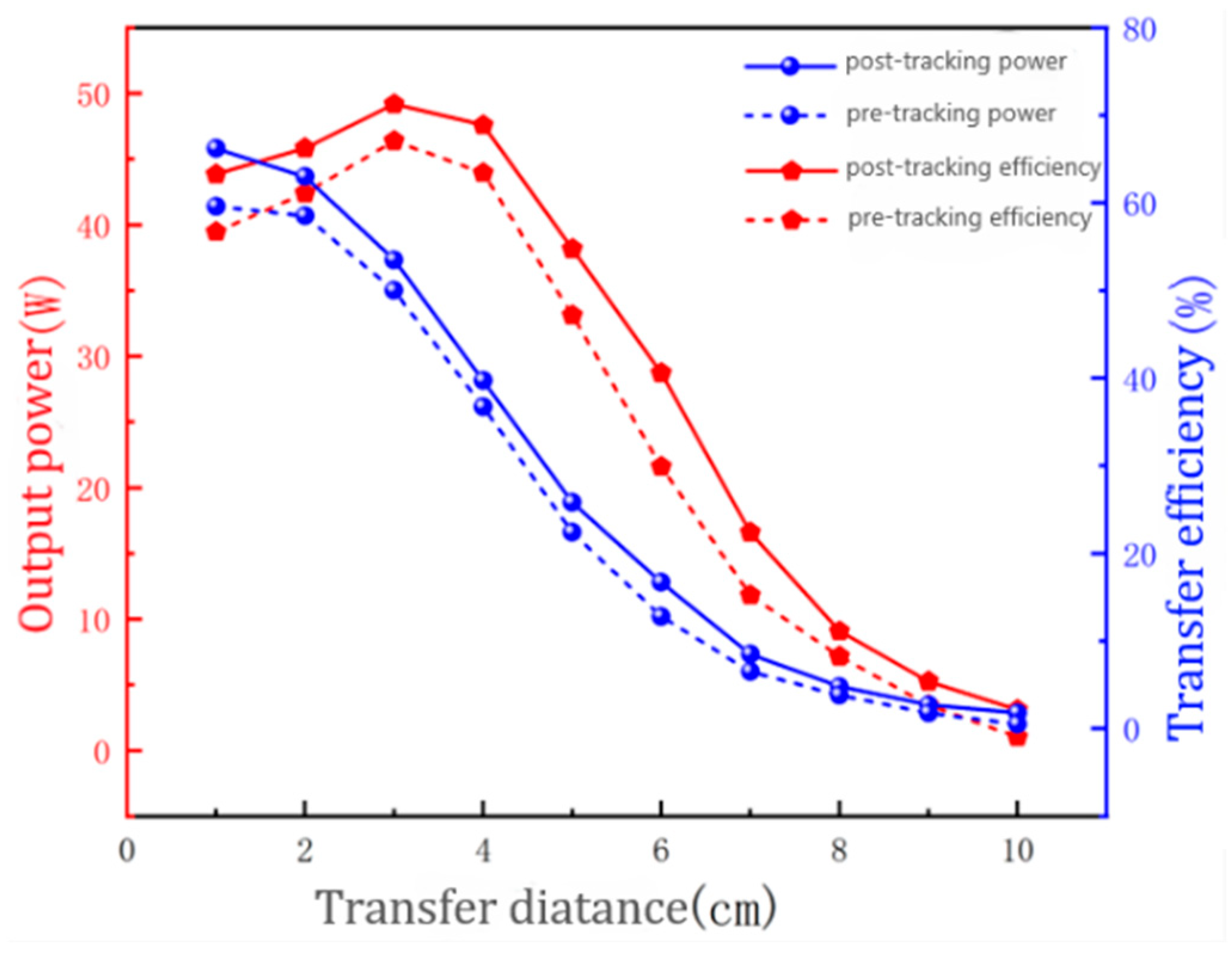
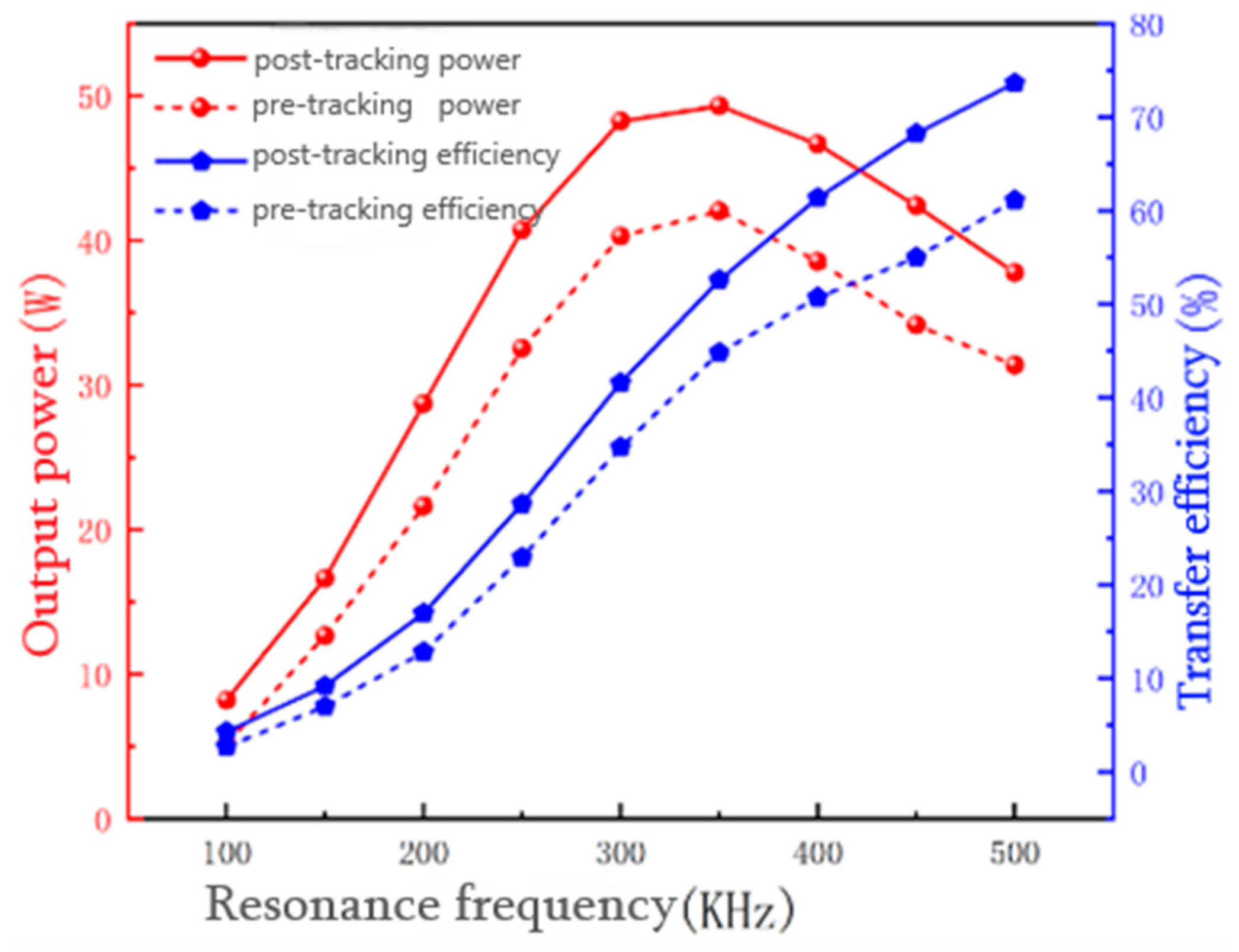
4.3. Transmission Performance Tests with Different Structural Parameters

In the system setup, the effects before and after frequency tracking were compared under different transmission distances and transmission frequency conditions. The comparison results are shown in Figure 16 and Figure 17.
Based on comparative analysis, the actual measurement results align with the theoretical analysis when varying the wireless power transfer distance. After implementing frequency-locking tracking, the quality of wireless transmission was significantly improved. Under the given parameters, the output power and transmission efficiency achieved a maximum increase of 5 W and 6.6%, respectively. Similarly, when the system’s resonance frequency was altered, frequency-locking tracking further enhanced power transfer, reaching a maximum increase of 8 W and an optimized transmission efficiency improvement of up to 13% [22,23].

5. Summary and Outlook

Regarding current research hotspots in the MCR-WPT field, the technology presented in this paper enhances the operational performance of wireless power transmission. By delving into theoretical algorithms and circuit structures, it provides a detailed analysis of the influencing factors in the Magnetic Coupling Resonance process. An optimized coil structure solution for the transmitter and receiver modules was proposed, improving design efficiency. The implementation of real-time full-spectrum frequency-locking tracking effectively enhanced wireless power transmission quality. Under the given operating conditions, the proposed method achieved power improvements of 5–8 W and transmission efficiency enhancements of 6–13%. Future work will focus on further exploring other resonance methods and coil structures while conducting a detailed analysis of power losses in each stage of the system to maximize wireless power transfer performance.

Author Contributions

Conceptualization, S.L. and J.L.; methodology, S.L.; software, J.L.; validation, S.L.; formal analysis, J.L.; investigation, H.Z.; resources, H.Z.; data curation, S.L.; writing—original draft preparation, S.L.; writing—review and editing, H.Z.; visualization, H.Z.; supervision, J.L.; project administration, H.Z.; funding acquisition, S.L. All authors have read and agreed to the published version of the manuscript.

Funding

This study was funded by the National Natural Science Foundation of China (62201523).

Data Availability Statement

The data underlying the results presented in this paper are not publicly available at this time but may be obtained from the authors upon reasonable request.

Conflicts of Interest

The authors declare no conflicts of interest.

References

  1. Li, X.; Zhang, H.; Peng, F.; Li, Y.; Yang, T.; Wang, B.; Fang, D. A Wireless Magnetic Resonance Energy Transfer System for Micro Implantable Medical Sensors. Sensors 2012, 12, 10292–10308. [Google Scholar] [CrossRef] [PubMed]
  2. Zhou, W.; Sandeep, S.; Wu, P.; Yang, P.; Yu, W.; Huang, S.Y. A Wideband Strongly Coupled Magnetic Resonance Wireless Power Transfer System and Its Circuit Analysis. IEEE Microw. Wirel. Compon. Lett. 2018, 28, 1152–1154. [Google Scholar] [CrossRef]
  3. Pries, J.; Galigekere, V.P.N.; Onar, O.C.; Su, G.J. A 50-kW Three-Phase Wireless Power Transfer System Using Bipolar Windings and Series Resonant Networks for Rotating Magnetic Fields. IEEE Trans. Power Electron. 2020, 35, 4500–4517. [Google Scholar] [CrossRef]
  4. Lim, Y.; Tang, H.; Lim, S.; Park, J. An Adaptive Impedance-Matching Network Based on a Novel Capacitor Matrix for Wireless Power Transfer. IEEE Trans. Power Electron. 2014, 29, 4403–4413. [Google Scholar] [CrossRef]
  5. Yuan, S.; Cui, Y.; Wang, J.; Fan, H.; Fan, Y. Research on impedance matching method for magnetically coupled resonant wireless energy transmission system. Ind. Min. Autom. 2019, 45, 6. [Google Scholar]
  6. Cheng, Z.; Lu, Y.; Liu, Q.; Xing, Y. Research on adaptive tuning of coupled resonant wireless energy transmission based on magnetic amplifier. J. Electrotechnol. 2018, 33, 8. [Google Scholar]
  7. Li, Y.; Dong, W.; Yang, Q.; Zhang, Q.; Liu, L. Power reduction mechanism and improvement method of over-coupled wireless energy transmission. J. Electrotechnol. 2018, 33, 8. [Google Scholar]
  8. Li, H.; Li, J.; Wang, K.; Chen, W.; Yang, X. A Maximum Efficiency Point Tracking Control Scheme for Wireless Power Transfer Systems Using Magnetic Resonant Coupling. IEEE Trans. Power Electron. 2015, 30, 3998–4008. [Google Scholar] [CrossRef]
  9. Cheng, L.; Cui, Y.; Yan, G. Research on frequency tracking control of magnetically coupled resonant wireless energy transmission. Power Electron. Technol. 2014, 48, 4. [Google Scholar]
  10. Zhou, H.; Yao, G.; Ma, L.; Wei, W. Research on resonant frequency tracking method of ICPT system. Power Electron. Technol. 2013, 47, 3. [Google Scholar]
  11. Liu, W.-T.; Li, Y.-X.; Cui, Y.; Huang, K.; Bian, X. FPGA-based frequency tracking control of magnetically coupled resonant wireless energy transmission. J. Electrotechnol. 2018, 33, 9. [Google Scholar] [CrossRef]
  12. Wang, W.J. Analysis and Design of Magnetically Coupled Resonant Wireless Power Supply System. Ph.D. Thesis, Anhui University of Technology, Maanshan, China, 2015. [Google Scholar]
  13. Liu, J. Design and Research of Wireless Energy Transmission System Based on Low-Frequency Compact Metamaterials. Ph.D. Thesis, Zhejiang University, Hangzhou, China, 2022. [Google Scholar]
  14. Li, D.; Qin, Q. The invention relates to an intermediate frequency power supply fast startand digital phase locked loop control technology. J. Phys. Conf. Ser. 2021, 2137, 012016. [Google Scholar] [CrossRef]
  15. Yang, Y.; Xu, Y.; Yao, W.; Chen, S. Efficiency analysis of three-coil resonant structure for wireless energy transmission system. Power Electron. Technol. 2020, 54, 27–29+38. [Google Scholar]
  16. Chen, X.; Zhou, A.; Mao, J.; Wang, P. Research on a multi-carrier access MCR WPT system with relay coil. Power Electron. Technol. 2021, 55, 114–117. [Google Scholar]
  17. Chen, F. Design of Wireless Power Supply System for Magnetically Coupled Resonant UAV. Ph.D. Thesis, Hebei University of Technology, Tianjin, China, 2017. [Google Scholar]
  18. Nguyen, M.Q.; Hughes, Z.; Woods, P.; Seo, Y.S.; Rao, S.; Chiao, J.C. Field Distribution Models of Spiral Coil for Misalignment Analysis in Wireless Power Transfer Systems. IEEE Trans. Microw. Theory Tech. 2014, 62, 920–930. [Google Scholar] [CrossRef]
  19. Chen, Q.; Fan, F.; Wang, J.; Chen, W.; Deng, X. Accurate evaluation method of Litz coil AC resistance for magnetic coupling system of wireless energy transmission. J. Electrotechnol. 2022, 37, 6294–6305. [Google Scholar]
  20. Li, C.; Zhang, H.; Cao, J.; Liu, M. Analysis and optimization of power and efficiency transmission characteristics of magnetic resonance coupled electric energy transmission system. Power Syst. Autom. 2015, 6, 92–97. [Google Scholar] [CrossRef]
  21. Li, Y.; Ma, J.; Li, M.; Liu, L.; Zhao, J.; Liu, X. Design and optimization of magnetic coupling coils for wireless energy transmission. Electr. Appl. Energy Effic. Manag. Technol. 2019, 56–62+70. [Google Scholar]
  22. Zou, Q.; Wang, J.; Yu, W.; Xu, X.; Liu, Y. Research on low-voltage high-current topology based on synchronous rectification technology. Electrotechnology 2022, 3, 74–76. [Google Scholar]
  23. Hao, H.; Zhang, X.; Guo, Y. Research and design of series-parallel wireless energy transmission system. Electron. Des. Eng. 2019, 27, 133–137. [Google Scholar]
Figure 1. Diagram of a magnetically coupled resonant wireless power transfer system.
Electronics 14 01152 g001
Figure 2. String resonance circuit output power.
Electronics 14 01152 g002
Figure 3. System diagram of the three-coil structure.
Electronics 14 01152 g003
Figure 4. A schematic diagram of the planar coiled-coil structure.
Electronics 14 01152 g004
Figure 5. The relationship between the mean radius, the number of turns, and the transmission characteristics of the system.
Electronics 14 01152 g005
Figure 6. System structure diagram of MCR-WPT.
Electronics 14 01152 g006
Figure 7. Structure diagram of phase-locked loop.
Electronics 14 01152 g007
Figure 8. Digital phase-locked loop model simulation diagram.
Electronics 14 01152 g008
Figure 9. Simulation of radio energy transmission system.
Electronics 14 01152 g009
Figure 10. Inverter voltage output waveforms.
Electronics 14 01152 g010
Figure 11. Transmitter voltage and current waveform with off-frequency tracking.
Electronics 14 01152 g011
Figure 12. Transmitter voltage and current waveform with on-frequency tracking.
Electronics 14 01152 g012
Figure 13. Output voltage waveform.
Electronics 14 01152 g013
Figure 14. Experimental platform.
Electronics 14 01152 g014
Figure 15. Frequency tracking effect test chart. (a) Frequency tracking not enabled. (b) Frequency tracking enabled.
Electronics 14 01152 g015
Figure 16. Relationship between coil distance and system transmission performance.
Electronics 14 01152 g016
Figure 17. The relationship diagram between the resonant frequency and the transmission characteristics of the system.
Electronics 14 01152 g017
Table 1. Comparison table of WPT methods.
WPT
Classification
Electromagnetic
Induction
(MIC-WPT)
Magnetically Coupled Resonant
(MCR-WPT)
Microwave
Radiometric
(MWPT)
transmission principlemagnetic couplingmagnetic couplingelectromagnetic
radiation
transmission distancecentimeter scalemeter scalekilometer scale
transmission powerkilowatt class (unit of electric power)kilowatt class (unit of electric power)megawatt-class
transmission efficiency>85%≈80%≈40%
operating
frequency
10 kHz–50 kHz20 kHz–500 MHz300 MHz–300 GHz
Table 2. Corresponding table of coil parameters and output power.
TurnsAverage Radius
14 cm15 cm16 cm17 cm18 cm19 cm20 cm
14248.857190.947150.486121.32599.73283.35970.684
15190.129145.706114.72892.43475.94363.45053.784
16147.638113.03688.94371.62258.82049.12841.634
17116.31988.99269.98556.33346.25038.62032.722
1892.84470.99055.80544.90536.85830.77126.068
1974.98157.30545.03236.22629.72924.81521.020
2061.20146.75536.73129.54324.24020.23117.135
Table 3. Corresponding table of coil parameters and transmission efficiency.
Number of TurnsAverage Radius
14 cm15 cm16 cm17 cm18 cm19 cm20 cm
1497.83598.13698.35098.50598.61998.70498.767
1598.14398.38398.55298.67298.75898.82198.866
1698.37498.56798.67098.79398.85798.90298.933
1798.55098.70498.80998.88098.92898.95998.978
1898.68498.80898.88998.94398.97798.99699.006
1998.78698.88598.94898.98799.00999.02099.021
2098.86598.94398.99199.01899.03099.03299.027
Disclaimer/Publisher’s Note: The statements, opinions and data contained in all publications are solely those of the individual author(s) and contributor(s) and not of MDPI and/or the editor(s). MDPI and/or the editor(s) disclaim responsibility for any injury to people or property resulting from any ideas, methods, instructions or products referred to in the content.

