Technical Note

Distributed Event-Triggered Current Sharing Consensus-Based Adaptive Droop Control of DC Microgrid

College of Electrical and Information Engineering, Hunan University of Technology, Zhuzhou 412007, China
*
Author to whom correspondence should be addressed.
Electronics 2025, 14(6), 1217; https://doi.org/10.3390/electronics14061217
Submission received: 24 February 2025 / Revised: 16 March 2025 / Accepted: 17 March 2025 / Published: 20 March 2025

Abstract

:
Conventional droop control (a decentralized method to regulate power sharing by adjusting voltage–current slopes) in DC microgrids faces challenges in balancing precise current distribution, bus voltage regulation, and communication pressure, especially in distributed energy management scenarios. To address these limitations, this paper proposes an adaptive control strategy combining three layers: (1) Primary control achieves power sharing and voltage stabilization via U-I droop characteristics for distributed energy resources (DERs); (2) Secondary control corrects voltage deviations and droop coefficient imbalances through multi-agent consensus algorithms, ensuring global equilibrium; (3) Event-triggered consensus control minimizes communication pressure via a novel protocol with time-varying coupling weights and a hybrid trigger function combining state variables and time-decaying terms rigorously proven to exclude Zeno behavior (i.e., infinite triggering in finite time) using Lyapunov stability theory.

1. Introduction

Integrating renewable energy sources (RES) into modern power systems has propelled DC microgrids to the forefront of smart grid research, owing to their superior efficiency, reduced conversion losses, and seamless compatibility with photovoltaic and battery storage systems [1,2,3]. Central to DC microgrid operation is the challenge of power sharing among distributed energy resources (DERs), where conventional droop control—a decentralized method of adjusting voltage–current slopes—has long been the industry standard [4]. However, this approach is fundamentally constrained by an inherent trade-off: increasing droop coefficients improves current sharing accuracy but exacerbates DC bus voltage deviations while reducing Ki stabilizes voltage at the expense of precision [5]. For instance, in a six-inverter microgrid with heterogeneous line impedances, traditional droop control fails to simultaneously achieve proportional current distribution and voltage regulation. This dilemma is further compounded by the communication pressure of distributed energy management systems, where existing solutions either rely on continuous state exchanges or neglect scalability in large-scale networks [6].
Recent advancements in DC microgrid control have focused on three primary directions, each addressing facets of the voltage–current trade-off yet introducing new limitations:
Secondary Voltage Restoration: Average voltage compensation [7,8] and global sag gain adjustment [9] mitigate voltage deviations by injecting compensation terms into droop characteristics. While effective in stabilizing bus voltage, these methods require continuous communication of global parameters (e.g., total load current), leading to high bandwidth demands (>10 kHz) incompatible with resource-constrained networks [10]. Consensus-based secondary control [11,12] dynamically adjusts voltage deviation via local agent interactions. However, protocols described in [11,12] depend on Laplacian matrix eigenvalues for stability guarantees, necessitating centralized topology calibration [13]—a contradiction to the distributed ethos of microgrids. Recent efforts, such as Huang et al. [14], propose fixed-time event-triggered consensus for fault-tolerant control in shipboard microgrids, achieving robustness against actuator faults. However, their reliance on homogeneous system models limits applicability to heterogeneous DERs, in general, DC microgrids.
Line Impedance Compensation: Adaptive droop coefficients [15,16] estimate line impedances to adjust the droop coefficient dynamically, reducing current sharing errors to ~0.5%. However, these methods struggle with transient load changes due to slow impedance estimation convergence [17]. Virtual impedance techniques [18,19] introduce software-defined impedance terms to counteract physical line mismatches. Yet, they require high-frequency PWM signal adjustments, increasing computational complexity, and inverter switching losses.
Event-Triggered Communication: Periodic sampling [20] reduces communication frequency by updating states at fixed intervals (e.g., 1 ms). While simple to implement, such schemes incur excessive resource usage (>1.2 M events/6 s) and lack adaptability to dynamic conditions [21].
State-dependent triggers [22,23] transmit data only when local errors exceed thresholds. Although reducing communication by 60–80%, these protocols risk Zeno behavior (infinite triggering in finite time) or rely on global topology knowledge for stability [24].
Leader–follower architectures [23,24] prioritize critical agents to enhance scalability but neglect proportional current sharing, limiting their applicability in peer-to-peer microgrids.
Despite these efforts, most event-triggered methods [21,22] require prior knowledge of network eigenvalues or fixed communication topologies, hindering plug-and-play DER integration. Communication-Accuracy Trade-off: Existing protocols [18,19,20] force a stark choice between precision (e.g., 0.05% error in [23]) and communication efficiency (e.g., 1.2 M events/6 s in [20]). Legacy System Compatibility: Retrofitting adaptive protocols into traditional droop-controlled systems risks transient instability during hybrid operation (e.g., voltage oscillations in [25]).
Recent studies in Electronics [6,12,19] have advanced distributed control strategies for islanded microgrids, particularly in addressing communication overhead and dynamic uncertainties. However, these approaches often rely on fixed communication topologies or centralized coordination, limiting their applicability to plug-and-play DER integration. Our work builds on these foundations by introducing dynamic coupling weights and a hybrid event-triggered protocol to resolve these limitations.
To resolve these challenges, this paper proposes a three-layer hierarchical control framework that synergizes adaptive droop compensation with a fully distributed event-triggered protocol. The key innovations are as follows:
  • Hybrid Event-Triggered Protocol: A novel triggering function) combines state-dependent errors, time-decaying terms, and dynamic coupling weights to eliminate Zeno behavior and reduce communication by 99.975% compared to periodic schemes. Rigorous Lyapunov analysis proves global asymptotic stability without requiring Laplacian eigenvalues, enabling a topology-agnostic operation.
  • Dynamic Droop Compensation: Consensus-driven slope adaptation: Secondary control iteratively adjusts droop coefficients via PI-regulated consensus errors, achieving proportional current sharing with <0.015% error under varying line impedances. Voltage intercept compensation: A PI controller eliminates steady-state voltage deviations by dynamically tuning ΔUi.
  • Backward-Compatible Design: The protocol’s time-varying coupling weights and local triggering conditions enable seamless integration with legacy droop-controlled inverters, avoiding layer conflicts. Transitional stability during phased deployments is ensured through hybrid Lyapunov functions, as validated in fault scenarios.
These contributions collectively advance DC microgrid control by resolving the voltage–current trade-off while ensuring scalability, resource efficiency, and backward compatibility—a critical enabler for next-generation smart grids.

2. DC Microgrid Hierarchical Control

2.1. Conventional Droop Control and Its Limitations

In a DC microgrid, distributed power is connected to the DC bus through a converter, and the output characteristics of the converter are changed through droop control to realize reasonable power distribution.
Power supply i and power supply j are connected in parallel in the DC microgrid, and the equivalent circuit is shown in Figure 1. Ki and Kj denote the droop coefficients of power supply i and power supply j, and ri and rj denote the line impedances between power supply i and power supply j and the DC bus. Uref is the reference voltage, Uoi and Uoj are the output voltages of the two power supplies after passing through the inverter, Ioi and Ioj are the output currents of the two sources after passing through the inverter, Ubus is the DC bus voltage and RL is the load.
For two DC sources i, j connected in parallel, the expression for conventional droop control is as follows:
U o i = U r e f K i I o i U o j = U r e f K j I o j
The DC microgrid makes the voltage and current linear by droop control, and the slope of the droop characteristic curve Ki is the droop coefficient.
From Figure 1 combined with Kirchhoff’s voltage law and Kirchhoff’s current law, the expression for the droop control characteristic can be obtained as follows:
U r e f I o i ( K i + r i ) I L R L = 0 U r e f I o j ( K j + r j ) I L R L = 0 I o i + I o j I L = 0
The associative equation is as follows:
I o i = ( K j + r j ) U r e f ( K i + r i ) ( K j + r j ) + ( K i + r i ) R L + ( K j + r j ) R L I o j = ( K i + r i ) U r e f ( K i + r i ) ( K j + r j ) + ( K i + r i ) R L + ( K j + r j ) R L
Furthermore, the ratio of Ioi to Ioj can be obtained as follows:
I o i I o j = K j + r j K i + r i K j K i ( K i > > r i , K j > > r j )
Generally, when Ki >> ri and Kj >> rj are satisfied, the line impedance is negligible, making the ratio of the output current Ioi to Ioj the inverse of the droop coefficient. Extended to multiple distributed power sources grid-connected, by setting the magnitude of the ratio of the droop coefficients of the power sources, the distribution of the current magnitude can be realized to achieve the effect of proportional distribution of power. However, the line impedance in the actual situation cannot be ignored, so the droop control in the actual situation can not realize the accurate distribution of the line current.
According to the principle of droop control, increasing the droop coefficient reduces the error caused by the line impedance, but leads to a larger voltage drop, resulting in an excessive deviation between the DC bus voltage Ubus and the reference voltage Uref. Reducing the droop coefficient reduces the voltage deviation but does not allow for accurate power distribution. This is the limitation of droop control, i.e., conventional droop control is unable to combine high-precision power distribution with DC bus voltage regulation.
These limitations highlight the need for a control strategy that not only resolves the voltage–current trade-off but also minimizes communication pressure in distributed energy management.

2.2. DC Microgrid Hierarchical Control Architecture

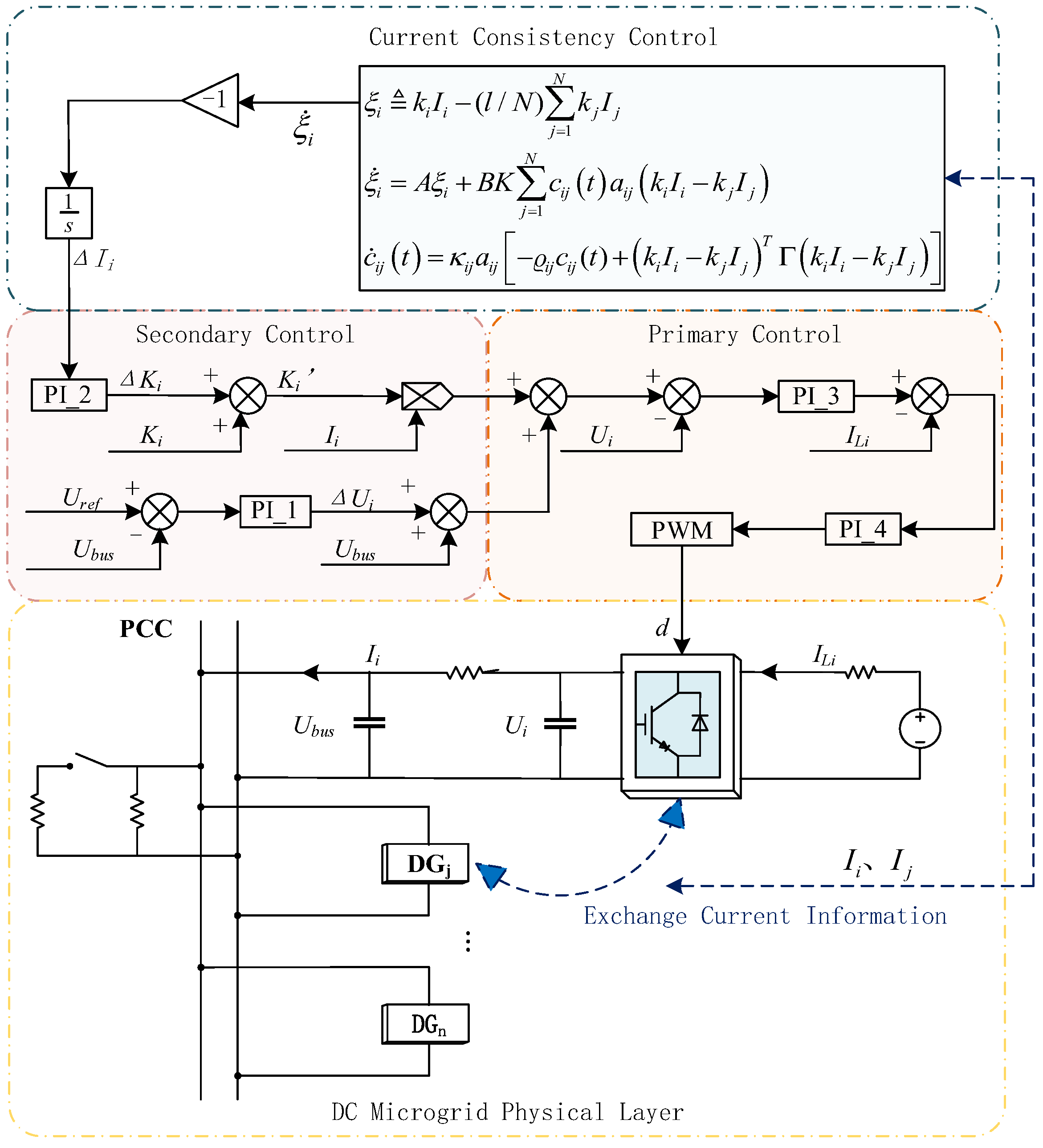
To bridge this gap, we propose a three-layer hierarchical control framework integrating primary, secondary, and event-triggered consensus layers. This architecture aims to achieve the following: (1) proportional current distribution under varying line impedances, (2) eliminate DC bus voltage deviations through dynamic compensation, and (3) reduce communication dependency via adaptive event-triggered protocols. Specifically, in order to realize the proportional distribution of output current when DC power sources are connected to the grid under different line impedances, and at the same time to ensure that the DC bus voltage is maintained at the rated value, this paper improves on the basis of the traditional droop control and extends the double shunt converter to the multiple shunt converter control structure, and proposes a hierarchical control method of DC microgrid based on the consistency algorithm, which is shown in the control schematic Figure 2.
The proposed hierarchical control framework comprises three layers:
  • Primary control: Local droop control and voltage/current loops for power sharing and stabilization.
  • Secondary control: Consensus-driven compensation of droop coefficients (ΔKi) and voltage deviations (ΔUi).
  • Event-triggered consensus control: Adaptive protocols to minimize communication pressure.
Among them, the primary control information exchange is carried out locally to realize power distribution and voltage stabilization and guarantee the reliable operation of the system. It contains droop control, voltage-loop control, and current control loop, where the voltage reference value is obtained through droop control, the voltage adaptive adjustment is realized through voltage-loop control, the power stabilization is realized through current control loop, and the control effect is achieved by controlling the inverter switch in the form of duty cycle.
Only the inverter output current of the secondary control requires information exchange between units, the rest is local control, which is used to optimize the droop control and improve the control accuracy. Droop coefficient compensation and voltage compensation are integrated into the primary control loop to achieve high-precision voltage regulation and current equalization. The droop coefficient compensation is dynamically adjusted based on the average consensus error of current sharing, calculated iteratively via a PI controller. Simultaneously, the voltage compensation is derived from the deviation between the actual DC bus voltage (Ubus) and the reference value (Uref), regulated by another PI controller.To realize the proportionality of the output current of each power source, it is necessary to ensure that the droop control coefficient is proportional to the corresponding proportion, and the variable ∆Ki is introduced as the compensation amount of the droop coefficient in the DGi inverter, at this time, the microgrid droop control expression is as follows:
U b u s = U r e f ( K i + r i + Δ K i ) I i
where Ki is the droop coefficient of DGi, ri is the line impedance between the DGi inverter, and the DC bus. Uref is the reference voltage, Ubus is the DC bus voltage at the common access point, and Ii is the output current of DGi after passing through the inverter.
By controlling the amount of droop coefficient compensation ∆Ki, the overall droop coefficient becomes proportional to its magnitude. This ensures that the current magnitude is inversely proportional to the droop coefficient. Consequently, power is distributed in the desired ratio.
( K i + r i + Δ K i ) I i = c o n s t
Due to the presence of the line impedance and the characteristics of the droop control itself, the DC bus voltage Ubus is less than the reference voltage Uref, i.e., there is a steady-state error in the DC bus voltage. To eliminate the error, it is necessary to add the voltage compensation amount ΔUi. ΔUi is expressed as follows:
Δ U i = ( U r e f U b u s ) · G P I 1 ( s )
where G P I 1 s is the PI_1 controller transfer function for the compensation voltage.
The droop control expression for DGi after secondary control is as follows:
U b u s = U r e f ( K i + Δ K i + r i ) I i + Δ U i
When Δ U i = K i + Δ K i + r i I i   U b u s = U r e f , the voltage deviation is eliminated, the DC bus voltage remains stable.
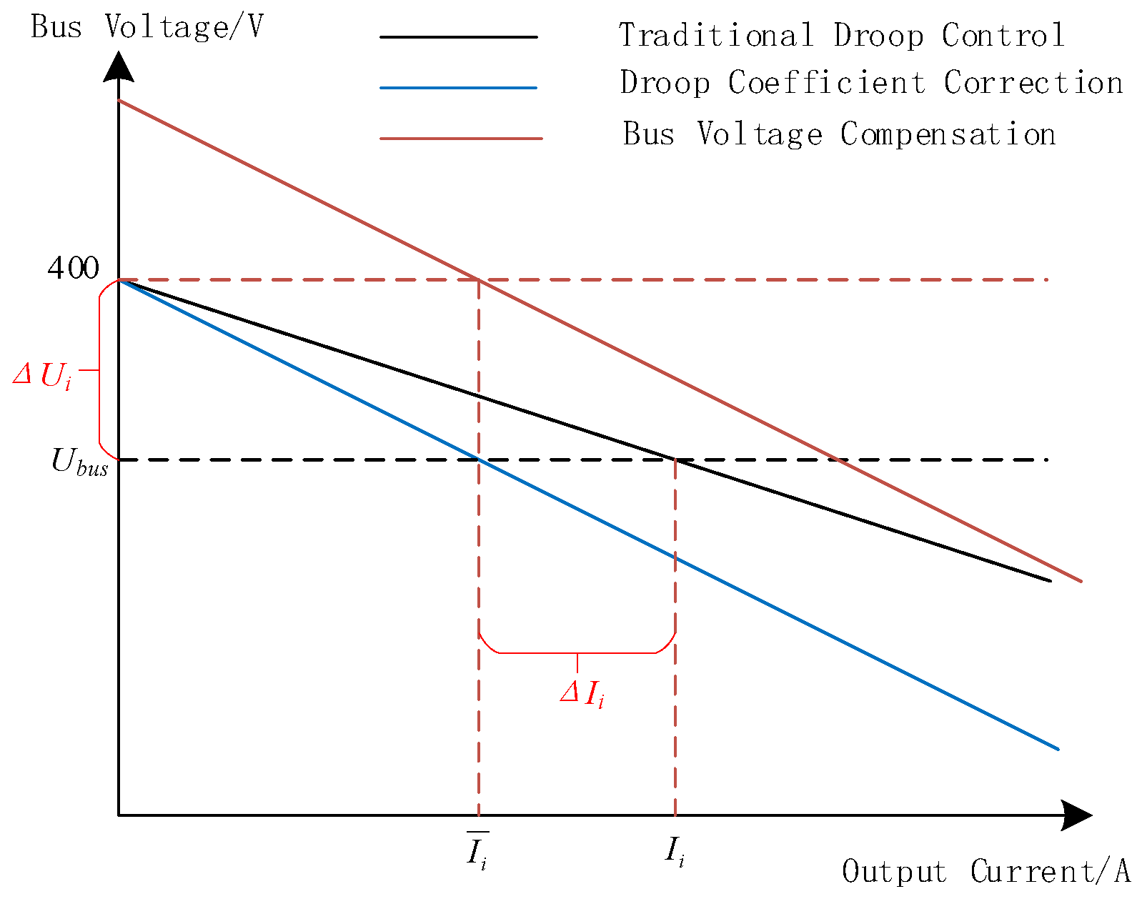
As shown in Figure 3, the slope of the droop characteristic curve is adjusted by the droop coefficient compensation so that the output current of DGi reaches I ¯ i , k 1 I ¯ 1 = k 2 I ¯ 2 = k i I ¯ i , realizing that the current is proportional and consistent, where ki is proportional to the droop coefficient Ki and the current Ii is inversely proportional to the droop coefficient Ki. The intercept of the droop characteristic curve is adjusted by voltage compensation to bring the DC bus voltage back to the reference value Uref, which realizes the power equalization and the return of the DC bus voltage to the reference value.

3. Event-Triggered Current Sharing Consensus Control

The realization of distributed secondary control for hierarchical control of microgrids that relies on continuous state measurements and information exchanges is prone to problems such as high cost, traffic congestion, and limited network protection functions. To reduce communication pressure and avoid excessive consumption of computational resources, a current sharing consensus control protocol based on an event-triggered mechanism is proposed, and the consistency problem is transformed into a corresponding error system stability problem.

3.1. Event-Triggered Conformance Protocol Design

To achieve coordinated control among multiple units, the DGs in a DC microgrid are viewed as intelligence in the system, and they utilize the communication between themselves and neighboring intelligences to achieve the regulation of their own voltage and current.
The dynamics of the i-th agent in a network of N linear systems are expressed as follows:
x ˙ i = A x i + B u i ,   i = 1 , , N
where xiR(n) and uiR(p) denote the state and control input of the ith intelligent, respectively.
The expression of the classical consistency algorithm is u i ( t ) = j N i a i j ( x i ( t ) x j ( t ) ) , and the control objective is to ensure that l i m t x i x j = 0 , for nodes i, j, if there exists a communication from node i to j, then aij = 1, aii = 0 otherwise aij = 0. For details on the theory of graph theory and consistency algorithms, see the literature.
To achieve proportional sharing of current, the control objective is extended to ensure that t when k 1 I 1 = k 2 I 2 = = k n I n .
The line current state estimate of DGi is defined as I ˜ i ( t ) = e A t t k i I i ( t k i ) , where t [ t k i , t k + 1 i ) , t k i denotes the kth triggering moment of DGi and the triggering moments t 0 i ,   t 1 i …, are determined by the triggering function. The current measurement error of DGi is defined as e i ( t ) I ¯ i ( t ) I i ( t ) ,   i = 1 , , N .
The adaptive current sharing consensus control protocol for DGi is designed as follows:
u i ( t ) = K j = 1 c i j ( t ) a i j ( k i I ˜ i ( t ) k j I ˜ j ( t ) )
Here, the time-varying coupling weights (cij(t)) dynamically adjusts communication between DGi and DGj, which is updated as follows:
c ˙ i j ( t ) = κ i j a i j [ ϱ i j c i j ( t ) + ( k i I ˜ i ( t ) k j I ˜ j ( t ) ) T Γ ( k i I ˜ i ( t ) k j I ˜ j ( t ) ) ] ,   i = 1 , , N
The trigger function includes the following hybrid terms:
f i ( t ) = j = 1 N 1 + δ c i j a i j e i T Γ e i 1 4 Σ j = 1 N a i j k i I ˜ i k j I ˜ j T Γ k i I ˜ i k j I ˜ j μ i e ν i t
where δ , μ , and ν are positive constants, and the trigger function contains error primary, state, and time decay variables, where the state-dependent and time-dependent terms reduce the number of event triggers and exclude Zeno behavior.
Design Steps:
1. Coupling Weights ( α i j ) : Initialize α i j ( 0 ) = α j i ( 0 ) for symmetry. Select κ _ i j > 0   e . g . ,   κ _ i j = 0.2 and ϱ i j < λ m a x ( P ) to balance adaptation speed and stability.
2. Trigger Function Parameters (δ, μ, ν) as follows:
δ: Determined via Lyapunov analysis to bound e i . For P > 0 solving algebraic Riccati equation (ARE), set δ = 1 / λ m i n P .
μ, ν: Chosen empirically with μ d e s i r e d   s t e a d y s t a t e   e r r o r and ν d e c a y   r a t e . In simulations, μ = 2 ,   ν = 0.5 .
3. Feedback Gains ( K , Γ ):
Solve the ARE P A + A T P P B B T P + I = 0   f o r   P > 0 .
Set K = B T P and Γ = P B B T P .
The trigger moments are t k + 1 i inf { t > t k i | f i t 0 } , t 0 i = 0 , and this protocol only relies on the event-triggered information of each DG and its neighbors and does not require continuous communication.
Let the output current state error between DGi and the remaining DGj be as follows: ξ ( t ) = [ ξ 1 T ( t ) , ξ 2 T ( t ) , , ξ N T ( t ) ] T where ξ i k i I i ( 1 / N ) j = 1 N k j I j .
The current sharing consensus is achieved when and only when the current sharing consensus is achieved, i.e., l i m t k i I i k j I j = 0 , at which point ξ = 0 , and hence ξ is defined as the current sharing consensus error, denoting the distance from DGi to the consistency target, and when the distance is 0, the current has reached the proportional mean, k 1 I ¯ 1 = k 2 I ¯ 2 = k i I ¯ i .
The current sharing consensus error ξ i after PI regulation is ΔKi which needs to be compensated into the droop coefficient. The expression of ΔKi is as follows:
Δ K i = ξ i · G P I 2 ( s )
where G P I 2 s is the PI_2 controller transfer function for the droop coefficient compensation amount.
The iterative equation for the current sharing consensus error is at the trigger moment t k i for the following:
ξ ˙ i = A ξ i + B K j = 1 N c i j t a i j k i I ˜ i k j I ˜ j
At this point, the system consistency problem is transformed into an error system stability problem without having to make multiple comparisons with the input current, saving computational costs.
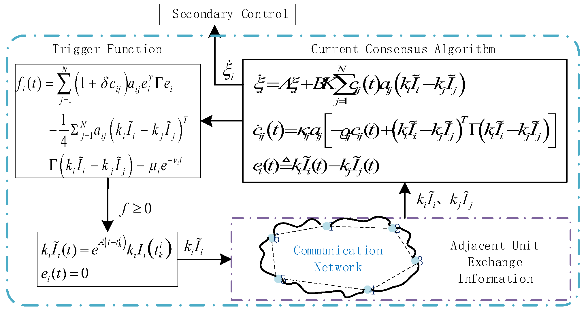
Figure 4 shows the control flowchart of the current sharing consensus algorithm based on the event-triggered mechanism proposed in this paper: the estimated value of the state of DGi is updated at the triggering instant, and the current state is updated to the controller (13) while propagating to the neighboring DGs while the measurement error e i t is normalized to 0. The other DGs update their own states when they receive the new state value. Its output current sharing consensus deviation is provided to the secondary control as a droop coefficient compensation quantity after integration and inversion. Conversely, DGi remains silent when the trigger function is less than zero.
Continuous communication is not required since the state update of the DG relies on communicating with neighbors sending sampled message states instead of real message states. The essence of event-triggered control is equivalent to transforming the real-time control problem of the original consistency algorithm into intermittent control.

3.2. Stability Analysis of Event-Triggered Mechanism

Proof of the event-triggering principle consisting of Equation (12). Define the Lyapunov candidate function as follows:
V = V 1 + α 2 i = 1 N μ i e ν i t
where V 1 = 1 2 i = 1 N ξ i T P ξ i + i = 1 N j = 1 , j i N ( c i j α ) 2 8 κ i j , and α is defined as a normal number by the following, and obviously V > 0 .
Calculate the derivative of V1 with respect to time as follows:
V ˙ 1 = i = 1 N ξ i T P ξ ˙ i + i = 1 N j = 1 , j i N c i j α 4 κ i j c ˙ i j = i = 1 N ξ i T P A ξ i + i = 1 N ξ i T P B K j = 1 N c i j a i j ( k i I ˜ i k j I ˜ j ) + i = 1 N j = 1 , j i N c i j α 4 κ i j c ˙ i j
Since, a i j = a j i ,   c i j = c j i ,   ξ i ξ j = k i x i k j x j ,   e i = k i ( I ˜ i I i ) , (16) is obtained by simplifying using Young’s inequality:
V ˙ 1 i = 1 N ξ i T P A ξ i α 4 i = 1 N j = 1 N a i j ( k i I ˜ i k j I ˜ j ) T Γ ( k i I ˜ i k j I ˜ j ) + i = 1 N j = 1 N c i j a i j e i T Γ e i i = 1 N j = 1 N c i j α 4 ϱ i j a i j c i j 1 2 ξ T I N ( P A + A T P ) α 4 L Γ ξ + α 2 i = 1 N j = 1 N 1 + 2 δ α · δ c i j a i j e i T Γ e i 1 4 j = 1 N a i j ( k i I ˜ i k j I ˜ j ) T Γ ( k i I ˜ i k j I ˜ j ) i = 1 N j = 1 N c i j α 4 ϱ i j a i j c i j
From the triggering mechanism (12), at the triggering intervals t [ t k i , t k + 1 i ) , f i ( t ) < 0 , i.e.,
V ˙ 1 1 2 ξ T I N ( P A + A T P ) α 4 L P B B T P ξ i = 1 N j = 1 N c i j α 4 ϱ i j a i j c i j + α 2 i = 1 N μ i e ν i t
Then, the derivative of V with respect to time can be expressed as follows:
V ˙ 1 2 ξ T I N ( P A + A T P ) α 4 L P B B T P ξ i = 1 N j = 1 N c i j α 4 ϱ i j a i j c i j α i = 1 N ( α ν i 1 2 ) μ i e ν i t
where α is a number that satisfies α max { 2 / δ , 4 / λ 2 ( L ) , 1 / ( 2 v i ) } and is sufficiently large.
From the definition of ξ , we obtain ( 1 T I ) ξ = 0 . Additionally, since the communication network is an undirected fully connected graph, graph theory principles imply ξ T L Γ ξ λ 2 ( L ) ξ T ( I N Γ ) ξ . Here, λ 2 ( L ) represents the smallest nonzero eigenvalue of the Laplace matrix. Then, from the Riccati equation, the first part of the inequality is less than 0. Obviously, the right side of inequality is strictly less than 0, i.e., V ˙ 0 , at which the time of the system is asymptotically stable at the equilibrium position. This is the end of the proof using Equation (11) as the trigger function.

3.3. Feasibility Analysis of Event Triggered Mechanism

The above control is implemented on the premise that there is no Zeno behavior, i.e., an infinite number of event triggers occurring in a finite amount of time does not exist, which can be ensured by proving that the time interval between any two triggering moments must be positive.
For DGi, t t k i , t k + 1 i , e ˙ i = A e i i = 1 N c i j a i j B K ( k i I ˜ i k j I ˜ j ) when t k + 1 i < .
At this moment e i t the derivative between is as follows:
d e i ( t ) d t = e i T e i e ˙ i e ˙ i A e i + j = 1 N c i j a i j B K k i I ˜ i k j I ˜ j
Since ξ i and c i j are ultimately consistently bounded, k i I i k j I j v i , v j is also bounded. If the time interval between two consecutive trigger events needs to be bounded, then for any moment t t k i , t k + 1 i , e A t t k i is bounded. Since the average convergence value 1 / N j = 1 N e A t k i I i 0 = e A t j = 1 N k j I j is invariant to k i I i = ξ i + 1 / N j = 1 N k j I j , it follows that for any finite time there is x t which is also finite.
Thus, for any moment t t k i , t k + 1 i , k i I ˜ i k j I ˜ j = e A t t k i k i I i t k i e A t t k i k j I j t k i is also bounded, and t k i is the nearest event-triggered moment of DGj.
Let there exist positive constants c ¯ satisfying c i j c ¯ . It is obtained from Equation (20):
d e i ( t ) d t A e i + c ¯ σ i
σ i denotes the upper bound of j = 1 N a i j B K k i I ˜ i k j I ˜ j when going from t k i to t k + 1 i . Let a non-negative function satisfy:
φ ˙ = A φ + c ¯ σ i , φ ( 0 ) = e i ( t k i ) = 0
Then, we have e i t φ t t k i , where φ t is the solution of (22): φ t = c ¯ σ i / A e A t 1 .
Assume that the following inequality holds:
e i 2 μ i e ν i t d i K 2 ( 1 + δ c ¯ )
Derive the event trigger function f i 0 currently. According to Equation (23), take any boundary τ k i which is smaller than the event trigger intervals t k i to t k + 1 i and bring it into φ t to obtain the following:
c ¯ 2 σ i 2 A 2 ( e A τ k i 1 ) 2 μ i e ν i ( t k i + τ k i ) d i K 2 ( 1 + δ c ¯ )
Solve the above inequality as follows:
t k + 1 i t k i τ k i 1 A ln 1 + A c ¯ σ i K μ i e ν i ( t k i + τ k i ) d i ( 1 + δ c ¯ )
It can be shown that τ k i always exists and is positive for any finite time, i.e., the interval between any two triggering moments is strictly positive. When the rightmost side of the t inequality also tends to 0, i.e., k , t k i . Thus, there is no Zeno behavior for any finite time.

4. Simulation Verification

To verify the effectiveness and feasibility of the proposed improved droop control strategy, this study focuses on a current sharing consensus mechanism for microgrids. A single-bus grid-connected model was developed using MATLAB/Simulink, as shown in Figure 2 and Figure 4. The model integrates six parallel-connected photovoltaic power generation systems. The line impedances between the inverters and the DC bus are configured as follows: R1 = 0.1 Ω, R2 = 0.2 Ω, R3 = 0.3 Ω, R4 = 0.1 Ω, R5 = 0.2 Ω, and R6 = 0.3 Ω.
The specific parameters of the simulation of the DC microgrid, primary control, and secondary control sections are shown in Table 1.
Since the state variable in the consistency control method of this paper is current, which is one-dimensional data, the feedback gain matrices K and Γ are also one-dimensional variables, and K and Γ are taken as the opposite of each other in the present experiments, and if there is no special explanation, the values are set as K = 13 . The topology of the signaling network is a non-directional strong connection, i.e., each DG has mutual communication with each other, each DG communicates with each other, and the sampling time interval is set to 5 × 10 6 s.

4.1. Effect of Hierarchical Control of Load Changes

This subsection simulates the control performance of two strategies during sudden load changes. The traditional droop control is compared with the proposed hierarchical control method.
Voltage and current characteristics under conventional droop control are simulated. The test uses 40 Ω and 50 Ω loads connected in parallel. A load jump is implemented at 2 s from 0 to 2 s, only the 40 Ω load is active; from 2 to 4 s, the 50 Ω load is added in parallel; after 4 s, the 50 Ω load is disconnected. Figure 5 presents the output currents of the six generating units during load changes. Figure 6 illustrates the DC bus voltage dynamics under the same conditions.
Figure 5 shows that the output currents of the six DGs are proportionally distributed under the droop coefficients set in this paper, which verifies that the power distribution of the grid-connected shunt DC power generation unit is inversely proportional to the droop coefficient distribution. However, due to the existence of line impedance, there are some differences between the grid-connected currents of DG1, DG2, and DG3 and DG4, DG5, and DG6 with the same droop coefficient, and the line currents of the grid-connected DC power generation unit in parallel are not distributed proportionally and equally. Figure 6 shows that due to the inherent defects of the droop control, there is a large gap between the DC bus voltage and the reference voltage, and the DC bus voltage is unstable after the change in load, and the load switching has a relatively large impact on the system.
The next step is to simulate and analyze the current and voltage characteristics of microgrid operation under hierarchical control with the addition of secondary control proposed in this paper, to verify the effectiveness of the improved droop control strategy with current sharing consensus under the event-triggered mechanism.
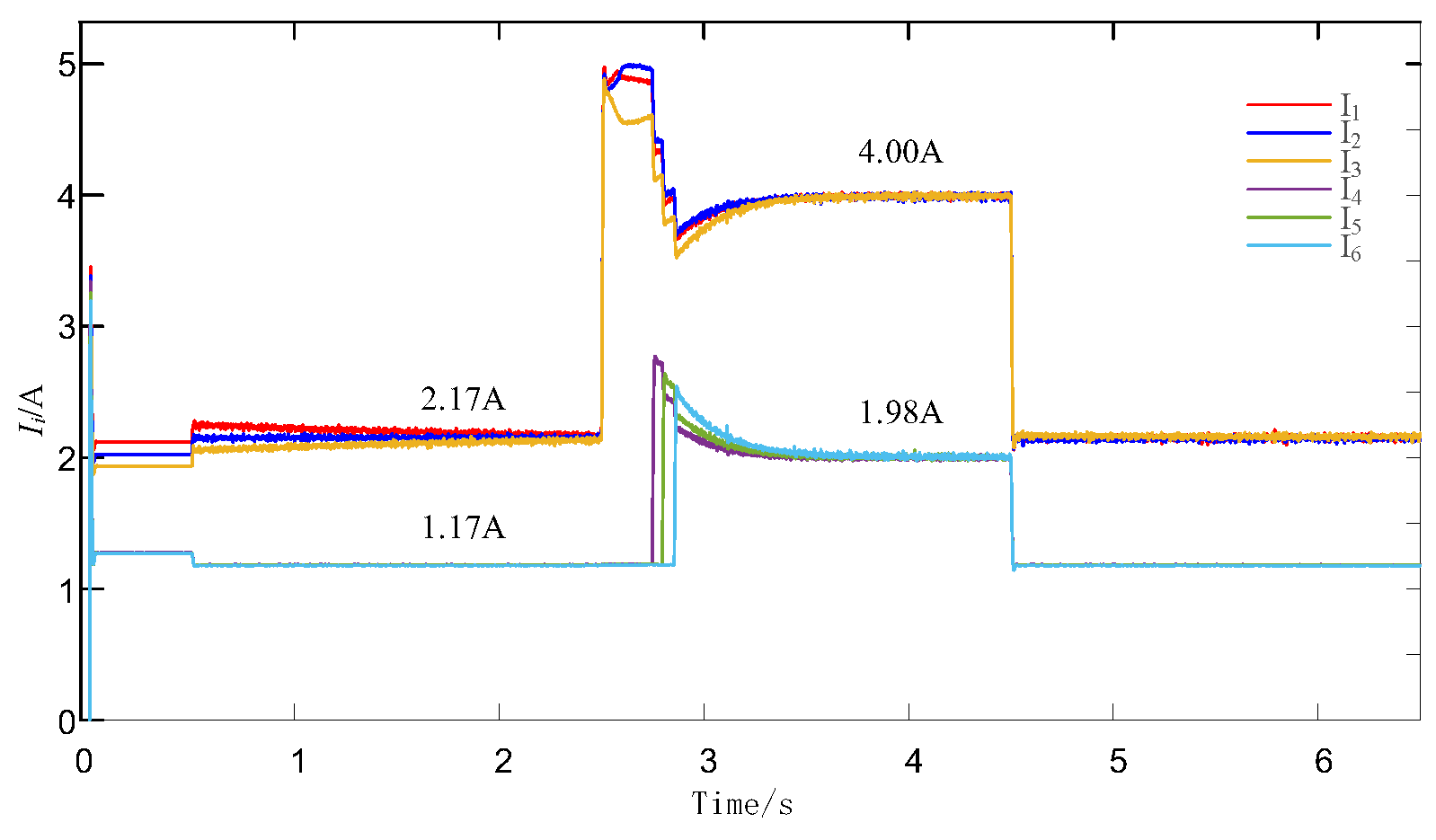
The secondary control is added at t = 0.5 s, and the load hopping is performed at 2.5 s and 4.5 s, respectively, i.e., the loads are 40 Ω and 50 Ω in parallel from 2.5 to 4.5 s, and 40 Ω from 4.5 to 6.5 s and 0.5 to 2.5 s. The simulation results are described below.
As shown in Figure 7, the proposed control strategy achieves proportional current distribution with an error of less than 0.015%, significantly outperforming traditional droop control, which exhibits an error of approximately 2%. The secondary control ensures that the currents of each line converge to the average value within 1.5 s, effectively compensating for the line impedance effects and improving the system’s dynamic response.
Figure 8 shows the schematic diagram of the DC bus voltage waveform under hierarchical control: the gap between the DC bus voltage and the reference value is large before 0.5 s, and the secondary control is added after 0.5 s, after which the DC bus voltage is quickly close to the reference voltage value, and the voltage change under the two load jumps is very small, and the DC bus voltage basically remains stable. The simulation results show that the secondary control proposed in this paper can maintain the DC bus voltage stable near the reference voltage value, achieve the stability of the system, and well optimize the traditional droop control.
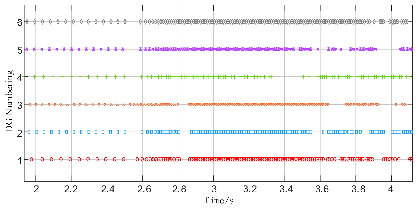
Figure 9 shows a schematic diagram of the event-triggered moments between the six DG’s when a load jump occurs, with each point indicating a trigger. From the figure, the number of communications increases significantly after a load jumps, but the number of communications also decreases slowly after the current is gradually stabilized, which indicates that the communication status of each DG depends only on its own and its neighbor’s current state and no event-triggered moments will be generated after the state is stabilized. The simulation results show that the distributed coherence control based on the event-triggered mechanism proposed in this paper does not rely on global communication and does not require continuous communication.

4.2. Simulation Analysis of Transformer Failures

The structure of the microgrid changes when the converter fails, and this subsection analyzes the stability and scalability of the control protocol for the inverter failure problem.
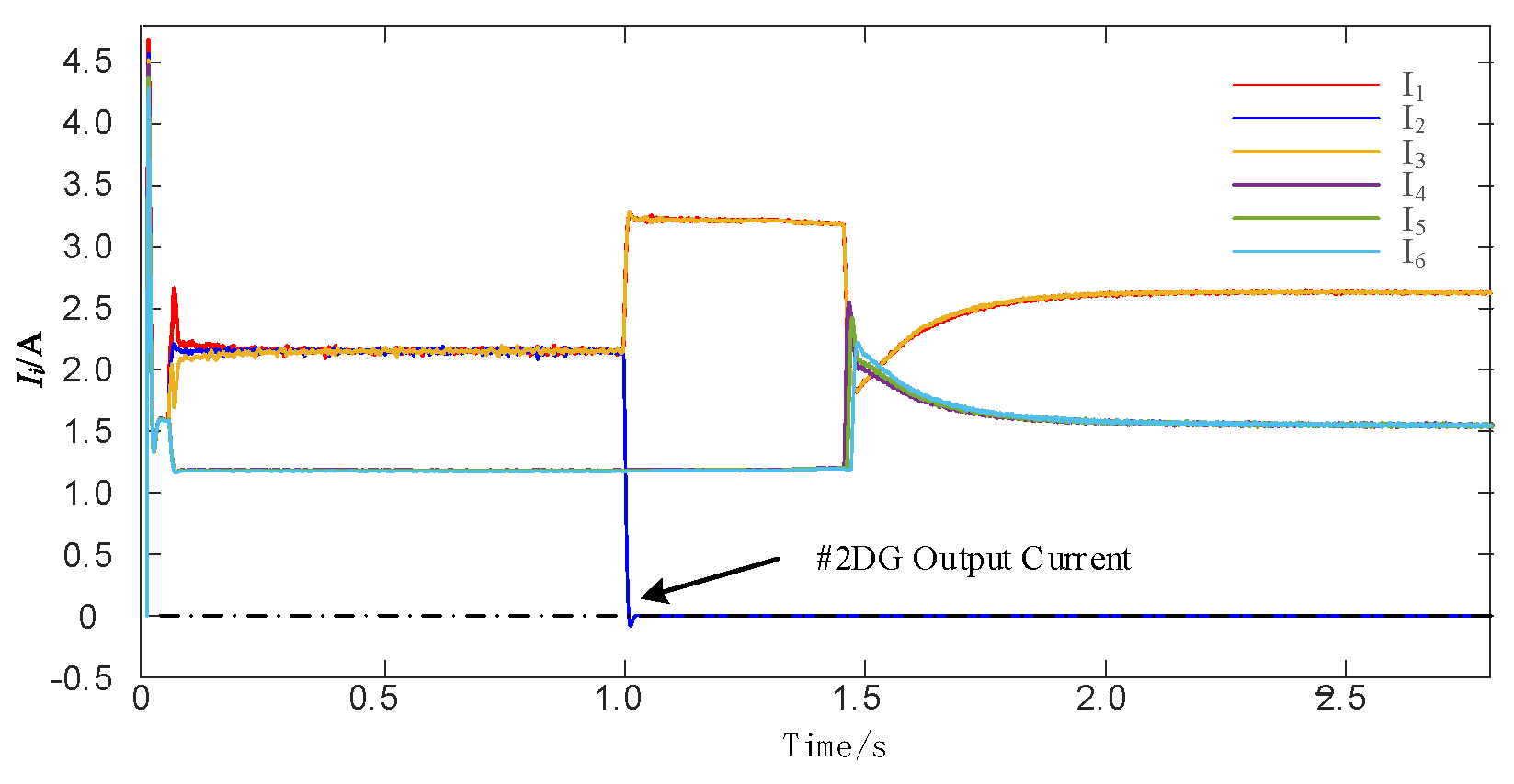
At t = 1 s, the No. 2 DG inverter is disconnected from the grid with a fault. Figure 10 and Figure 11 show the current output waveforms and voltage output waveforms of each DG before and after DG No. 2 is disconnected from the grid at t = 1 s. Figure 10 shows that after DG No. 2 is detached from the grid and the topology is changed, the output current of DG No. 2 decreases to 0 due to the inverter fault, and the other DGs quickly converge to the average value after 0.7 s, and the current distribution is not affected. The simulation results show that the change in network topology has no effect on the adaptive current-consistent droop control based on the event-triggered mechanism proposed in this paper, and the control protocol proposed in this paper is scalable.
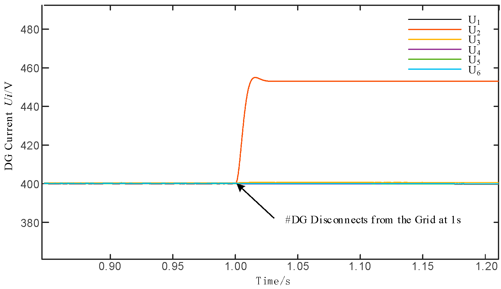
In Figure 11, after DG No. 2 is disconnected from the grid, the output voltage of DG No. 2 is the loop voltage of the inverter, and the output voltages of the other DGs remain at the reference value. The simulation results show that the hierarchical control of the DC microgrid proposed in this paper can continue to maintain the proportional power equalization as well as maintain the voltage stabilization at the reference value after the network topology is changed.

4.3. Communications Cost Analysis

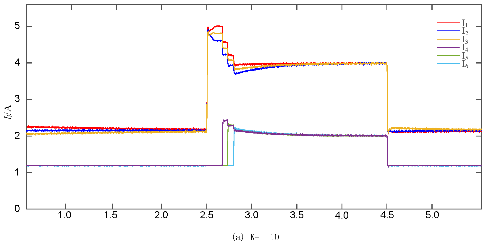
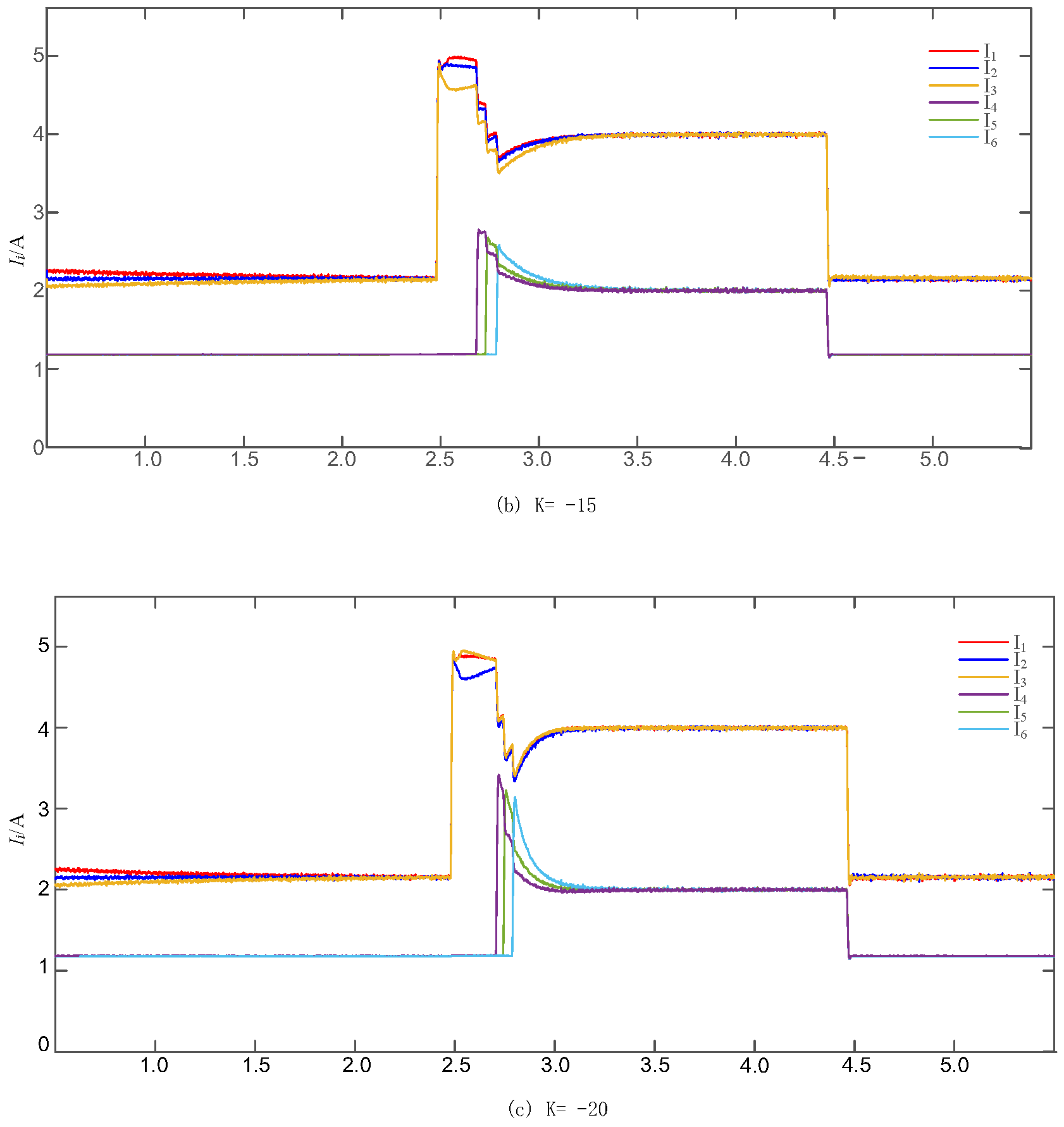
To verify the effectiveness of event-triggered to reduce the communication pressure, a simulation comparison between the periodic communication consistency control and the event-triggered consistency control proposed in this paper was carried out. Since different feedback gains K affects the convergence speed of the currents and the number of events triggered between the DGs, experiments were conducted in this subsection for the cases of K = −10, K = −15, and K = −20. In addition to verifying the economy of the proposed scheme, the number of events triggered between various types of inverters under discrete time consistent control as well as under the control of this paper under the same conditions were comparatively analyzed.
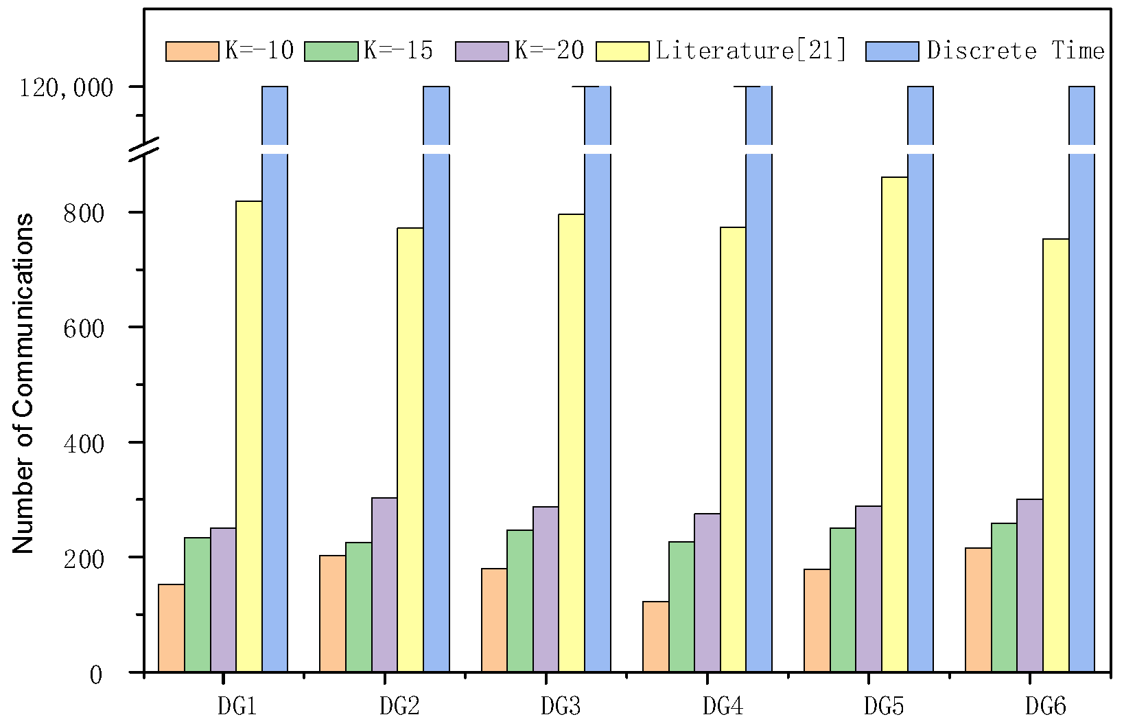
Firstly, the current convergence state of each inverter control under different feedback matrices was analyzed. Figure 12 shows the output current under the secondary control under the classical one-time algorithm when a load jump occurs, and Figure 13 shows the output current of each DG under the time-triggered coherent control proposed in this paper when a load jump occurs under the corresponding feedback matrices. Figure 14 shows the histogram of the number of events triggered in 6 s under event-triggered control with K = −10, K = −15, K = −20, the literature [21] control, and classical consistency control.
Simulation results show that the fully distributed event-triggered control proposed in this paper has a much lower communication pressure than periodic communications in the same situation. After increasing the value of the feedback matrix, the current converges faster, but the communication pressure is higher and the resistance to external disturbances is worse.
As shown in Figure 14, the sampling step of the simulation is 5 × 10 6 , for periodic communication classical consistency algorithms need to communicate in 6 s 1.2 × 10 6 This case is still using periodic communication, which is costly.
To highlight the advantages, we compare key characteristics with three representative strategies:
  • Traditional Droop Control [4]: A decentralized method with fixed droop coefficients.
  • Consensus-Based Secondary Control [18]: A continuous communication protocol for voltage restoration.
  • Periodic Event-Triggered Control [21]: A time-triggered mechanism with fixed intervals.
A detailed comparison of the advantages and disadvantages of each method is shown in Table 2. The proposed hybrid trigger function (Equation (12)) reduces line impedance effects, achieving a 30x improvement over [18]. By combining state-dependence and time-decaying triggers, the protocol reduces communication by 99.9% versus [21]. Unlike [18], which requires Laplacian eigenvalues, our method relies solely on local interactions. From Figure 7, the consensus error converges within 1.5 s, outperforming [18] (2.5 s) and [21] (3.0 s).
The proposed event-triggered control method reduces the maximum number of communications to 300 events within a 6 s simulation, achieving a communication pressure reduction of over 99.975% compared to the classical periodic communication algorithm, which requires 1.2 million communication events under the same conditions. This significant reduction in communication pressure highlights the economic efficiency of the proposed method.

5. Conclusions

This paper proposes a fully distributed event-triggered adaptive droop control strategy for DC microgrids, addressing the inherent trade-off between current sharing accuracy and voltage stability in conventional droop control. The hierarchical architecture—comprising primary droop control, consensus-based secondary compensation, and hybrid event-triggered protocols—achieves proportional current distribution with <0.015% error, eliminates DC bus voltage deviations (UbusUref < 0.09%), and reduces communication pressure by 99.975% compared to periodic schemes. Key innovations are as follows:
  • Hybrid Trigger Function: Combining state-dependent errors and time-decaying terms to exclude Zeno behavior while minimizing communication.
  • Topology-Independent Design: Time-varying coupling weights enable fully distributed control without global Laplacian eigenvalues.
  • Dynamic Compensation: Adaptive droop coefficients (ΔKi) and voltage intercepts (ΔUi) counteract line impedance effects.
Our future work will address these limitations:
  • Backward Compatibility with Traditional Droop Control: To facilitate real-world adoption, we will design threshold-only trigger functions for legacy inverters and analyze hybrid stability during phased upgrades [14].
  • Large-Scale Heterogeneous Systems: Extending the protocol to 50+-agent microgrids with PV, wind, and storage via virtual impedance matching.
  • Delay and Topology Adaptability: Developing delay-compensated triggers and sparse-topology weights for rural grids.
  • Cost-Effective Deployment: Optimizing dynamic compensation (ΔKi) for legacy systems without hardware upgrades.

Author Contributions

Conceptualization, J.Z. and T.L.; methodology, J.Z.; software, T.L.; validation, J.Z., T.L. and C.X.; formal analysis, J.Z.; investigation, J.Z.; resources, C.X. and Z.S.; data curation, T.L.; writing—original draft preparation, J.Z.; writing—review and editing, C.X. and Z.S.; visualization, T.L.; supervision, C.X. and Z.S.; project administration, J.Z.; funding acquisition, C.X. All authors have read and agreed to the published version of the manuscript.

Funding

This research was funded by State General Program of the National Natural Science Foundation of China (NSFC) under Grants 52377185 and 62373143.

Conflicts of Interest

The funders had no role in the design of the study; in the collection, analysis, or interpretation of data; in the writing of the manuscript; or in the decision to publish the results.

References

  1. Shahidehpour, M.; Zhou, Q.; Tian, Z.; Liu, X.; Alabdulwahab, A.; Abusorrah, A. Optimal consensus-based distributed control strategy for coordinated operation of networked microgrids. IEEE Trans. Power Syst. 2019, 35, 2452–2462. [Google Scholar]
  2. Zhao, H.; Qian, J.; Pan, H.; Jia, L. Adaptive voltage droop control of DC microgrid for island photovoltaic and energy storage. J. North China Electr. Power Univ. (Nat. Sci. Ed.) 2024, 51, 1–11. Available online: https://link.cnki.net/urlid/13.1212.TM.20240424.0959.002 (accessed on 21 July 2024).
  3. Anand, A.; Ranjan, A.; Devassy, S.; Verma, B.K.; Ram, S.K.; Dhakar, A.K. Review of hierarchical control strategies for DC microgrid. IET Renew. Power Gener. 2020, 14, 1631–1640. [Google Scholar]
  4. Ning, X.; Pan, H.; Li, F.; Wu, J. An improved droop control strategy for a DC microgrid based on online resistance observations. Power Syst. Prot. Control 2024, 52, 42–51. [Google Scholar]
  5. Lu, X.; Guerrero, J.M.; Sun, K.; Vasquez, J.C. An improved droop control method for DC microgrids based on low bandwidth communication with DC bus voltage restoration and enhanced current distribution accuracy. IEEE Trans. Power Electron. 2014, 29, 1800–1812. [Google Scholar] [CrossRef]
  6. Wan, X.; Wu, J. Distributed hierarchical control for islanded microgrids based on adjustable power consensus. Electronics 2022, 11, 324. [Google Scholar] [CrossRef]
  7. Mo, Z.; Sun, L. Research on SOC equalization control strategy of distributed energy storage considering line impedance. Electr. Power 2024, 121, 439. [Google Scholar]
  8. Dehkordi, N.M.; Sadati, N.; Hamzeh, M. Fully distributed cooperative secondary frequency and voltage control of islanded microgrids. IEEE Trans. Energy Convers. 2017, 32, 675–685. [Google Scholar] [CrossRef]
  9. Xia, C.; Shi, M.; Zhou, J.; Zuo, W.; Chen, Y.; Wen, J.; He, H. Consensus-based distributed control for photovoltaic-battery units in a DC microgrid. IEEE Trans. Ind. Electron. 2019, 66, 7778–7787. [Google Scholar]
  10. Zhou, Q.; Shahidehpour, M.; Li, Z.; Che, L.; Alabdulwahab, A.; Abusorrah, A. Compartmentalization strategy for the optimal economic operation of a hybrid AC/DC microgrid. IEEE Trans. Power Syst. 2020, 35, 1294–1304. [Google Scholar] [CrossRef]
  11. Wang, B.; Wang, Y.; Xu, Y.; Zhang, X.; Gooi, H.B.; Ukil, A.; Tan, X. Consensus-based control of hybrid energy storage system with a cascaded multiport converter in DC microgrids. IEEE Trans. Sustain. Energy 2019, 11, 2356–2366. [Google Scholar] [CrossRef]
  12. Al-Tameemi, Z.H.A.; Lie, T.T.; Foo, G.; Blaabjerg, F. Optimal coordinated control strategy of clustered DC microgrids under load-generation uncertainties based on GWO. Electronics 2022, 11, 1244. [Google Scholar] [CrossRef]
  13. Zeng, H.; Zhao, E.; Zhou, S.; Han, Y.; Yang, P.; Wang, C. Adaptive droop control of a DC microgrid based on current consistency. Power Syst. Prot. Control 2022, 50, 11–21. [Google Scholar]
  14. Huang, S.; Xiong, L.; Zhou, Y.; Gao, F.; Jia, Q.; Li, X.; Li, X.; Wang, Z.; Khan, M.W. Robust distributed fixed-time fault-tolerant control for shipboard microgrids with actuator fault. IEEE Trans. Transp. Electrific. 2024, 11, 1791–1804. [Google Scholar] [CrossRef]
  15. Ding, L.; Han, Q.; Ge, X.; Zhang, X.-M. An overview of recent advances in event-triggered consensus of multiagent systems. In Proceedings of the IEEE Conference on Cybernetics, Shenzhen, China, 10–12 December 2018; pp. 1110–1123. [Google Scholar]
  16. Chen, P.; Han, Q. On designing a novel self-triggered sampling scheme for networked control systems with data losses and communication delays. IEEE Trans. Ind. Electron. 2016, 63, 1239–1248. [Google Scholar]
  17. Abhinav, S.; Modares, H.; Lewis, F.L.; Davoudi, A. Resilient cooperative control of DC microgrids. IEEE Trans. Smart Grid 2019, 10, 1083–1085. [Google Scholar] [CrossRef]
  18. Chen, M.; Xiao, X.; Guerrero, J.M. Secondary restoration control of islanded microgrids with a decentralized event-triggered strategy. IEEE Trans. Ind. Inform. 2018, 14, 3870–3880. [Google Scholar] [CrossRef]
  19. Luo, Y.; Chen, M.; Kang, W.; Sun, X. Distributed event-triggered voltage control with limited reactive power in low-voltage distribution networks. Electronics 2021, 10, 128. [Google Scholar] [CrossRef]
  20. Chen, Z.; Yu, X.; Xu, W.; Wen, G. Modeling and control of islanded DC microgrid clusters with hierarchical event-triggered consensus algorithm. IEEE Trans. Circuits Syst. I 2021, 68, 376–386. [Google Scholar] [CrossRef]
  21. Peng, J.; Fan, B.; Tu, Z.; Zhang, W.; Liu, W. Distributed periodic event-triggered optimal control of DC microgrids based on virtual incremental cost. IEEE/CAA J. Autom. Sin. 2022, 9, 624–634. [Google Scholar] [CrossRef]
  22. Olfati-Saber, R.; Fax, A.J.; Murray, M.R. Consensus and cooperation in networked multi-agent systems. Proc. IEEE 2007, 95, 215–233. [Google Scholar] [CrossRef]
  23. Cheng, B.; Li, Z. Fully distributed event-triggered protocols for linear multiagent networks. IEEE Trans. Autom. Control 2019, 64, 1655–1662. [Google Scholar] [CrossRef]
  24. Meng, L.; Dragicevic, T.; Roldan-Perez, J.; Vasquez, J.C.; Guerrero, J.M. Modeling and sensitivity study of consensus algorithm-based distributed hierarchical control for DC microgrids. IEEE Trans. Smart Grid 2016, 7, 1504–1515. [Google Scholar] [CrossRef]
  25. Augustine, S.; Lakshminarasamma, N.; Mishra, M.K. Control of photovoltaic-based DC microgrid system. IET Power Electron. 2016, 9, 1132–1143. [Google Scholar] [CrossRef]
Figure 1. Equivalent circuit model of a DC microgrid with two parallel-connected DGs. Key parameters include droop coefficients (Ki, Kj), line impedances (ri, rj), reference voltage (Uref), and load resistance (RL).
Electronics 14 01217 g001
Figure 2. The proposed three-layer hierarchical control architecture for DC microgrids. The primary layer (local droop control) ensures power sharing; the secondary layer (consensus-based compensation) corrects voltage deviations and droop imbalances; the event-triggered layer minimizes communication via adaptive protocols. Hereafter, a single grid-connected DC power source is referred to as a DG.
Electronics 14 01217 g002
Figure 3. Adaptive U-I droop characteristics with dynamic slope (Ki + ΔKi) and voltage intercept (Uref + ΔUi) compensation. The adjusted curves (dashed lines) achieve proportional current sharing and restore DC bus voltage to Uref = 400 V.
Electronics 14 01217 g003
Figure 4. Event-triggered consensus control workflow. Each DG updates its state and broadcasts to neighbors only when the hybrid trigger condition (Equation (11)) is violated. Silent periods reduce communication by 99.9% compared to continuous protocols.
Electronics 14 01217 g004
Figure 5. Output currents of six DGs under traditional droop control during load step-changes (0–6 s), showing significant deviations (5%) due to line impedance effects. DG1–DG3 (droop coefficient Ki = 2) and DG4–DG6 (Ki = 4) exhibit unequal current sharing despite identical droop settings, validating the limitations of conventional methods.
Electronics 14 01217 g005
Figure 6. DC bus voltage under traditional droop control. Voltage deviations exceed 1% and fluctuate significantly during load steps (2 s and 4 s), highlighting poor voltage regulation.
Electronics 14 01217 g006
Figure 7. Output currents of six DGs under proposed hierarchical control. After activating secondary compensation at t = 0.5 s, currents converge to proportional sharing (2:2:2:1:1:1 ratio) with <0.015% error, despite line impedance variations.
Electronics 14 01217 g007
Figure 8. DC bus voltage recovery under hierarchical control with secondary compensation. After activating secondary control at t = 0.5 s, the voltage stabilizes at Uref = 400 V (error < 0.09%) despite load steps at 2.5 s and 4.5 s, demonstrating effective voltage regulation.
Electronics 14 01217 g008
Figure 9. Event-triggered communication frequency during load jumps (2.5 s and 4.5 s). Triggering peaks occur transiently after disturbances but decay rapidly (<50 events after 1 s), proving the protocol’s adaptability to dynamic condition.
Electronics 14 01217 g009
Figure 10. Current redistribution after DG2 disconnection at t = 1 s. Remaining DGs rebalance currents within 0.7 s, demonstrating system resilience to topology changes.
Electronics 14 01217 g010
Figure 11. DC bus voltage stability after DG2 disconnection. Voltage remains at Uref = 400 V ± 0.3%, validating the hierarchical control’s fault tolerance.
Electronics 14 01217 g011
Figure 12. Current distribution under continuous consensus control. Proportional sharing is achieved but requires 1.2 million communication events in 6 s, highlighting excessive resource usage.
Electronics 14 01217 g012
Figure 13. Current convergence under event-triggered control with varying feedback gains (K = −10, −15, −20). Higher ∣K∣ accelerates convergence but increases triggering frequency.
Electronics 14 01217 g013aElectronics 14 01217 g013b
Figure 14. Communication event reduction under event-triggered protocols. The proposed method reduces events by 99.975%.
Electronics 14 01217 g014
Table 1. Grid and inverter parameters.
ParametersNumerical Value
DC microgridsBusbar voltage rating Uref/V400
Power supply output voltage Ubus/V200
Load resistance RL140
Load resistance RL250
Bus-to-ground capacitance CBG/F4 × 10−5
Transformer capacitance CC/F4 × 10−5
Transformer inductance LC/F2 × 10−5
primary control layerCarrier frequency fcar/kHz10
Voltage loop controller (PI_3) parametersKP3 = 0.01
KI3 = 800
Current loop controller (PI_4) parametersKP4 = 500
KI4 = 30
secondary control layerFirst PI controller (PI_1) parametersKP1 = 10.0
KI1 = 0.03
Second PI controller (PI_2) parametersKP2 = 0.05
KI2 = 0.36
Event triggered layerFeedback gain K B T P
Γ P B B T P
κ i j 0.0325
ρ i j 0.0025
δ 2
μ 0.001
ν 1
Table 2. Comparative analysis of existing methods.
FeatureProposed MethodTraditional Droop [4]Consensus [18]Periodic [21]
Current Error<0.015%2.0%0.05%0.1%
Voltage Deviation0.09%1.5%0.2%0.3%
Communication Events300 (6 s)N/A1200 (6 s)1.2 M (6 s)
Topology DependencyFully DistributedLocal OnlyGlobal EigenvaluesFixed Intervals
Zeno BehaviorExcludedN/APartially AddressedNot Addressed
Disclaimer/Publisher’s Note: The statements, opinions and data contained in all publications are solely those of the individual author(s) and contributor(s) and not of MDPI and/or the editor(s). MDPI and/or the editor(s) disclaim responsibility for any injury to people or property resulting from any ideas, methods, instructions or products referred to in the content.